EP3647716A1 - Imaging device - Google Patents
Imaging device Download PDFInfo
- Publication number
- EP3647716A1 EP3647716A1 EP18823109.6A EP18823109A EP3647716A1 EP 3647716 A1 EP3647716 A1 EP 3647716A1 EP 18823109 A EP18823109 A EP 18823109A EP 3647716 A1 EP3647716 A1 EP 3647716A1
- Authority
- EP
- European Patent Office
- Prior art keywords
- image
- parallax
- unit
- optical axis
- imaging
- Prior art date
- Legal status (The legal status is an assumption and is not a legal conclusion. Google has not performed a legal analysis and makes no representation as to the accuracy of the status listed.)
- Pending
Links
Images

Classifications
-
- G—PHYSICS
- G06—COMPUTING OR CALCULATING; COUNTING
- G06T—IMAGE DATA PROCESSING OR GENERATION, IN GENERAL
- G06T7/00—Image analysis
- G06T7/80—Analysis of captured images to determine intrinsic or extrinsic camera parameters, i.e. camera calibration
- G06T7/85—Stereo camera calibration
-
- G—PHYSICS
- G01—MEASURING; TESTING
- G01C—MEASURING DISTANCES, LEVELS OR BEARINGS; SURVEYING; NAVIGATION; GYROSCOPIC INSTRUMENTS; PHOTOGRAMMETRY OR VIDEOGRAMMETRY
- G01C3/00—Measuring distances in line of sight; Optical rangefinders
- G01C3/02—Details
- G01C3/06—Use of electric means to obtain final indication
- G01C3/08—Use of electric radiation detectors
- G01C3/085—Use of electric radiation detectors with electronic parallax measurement
-
- G—PHYSICS
- G01—MEASURING; TESTING
- G01C—MEASURING DISTANCES, LEVELS OR BEARINGS; SURVEYING; NAVIGATION; GYROSCOPIC INSTRUMENTS; PHOTOGRAMMETRY OR VIDEOGRAMMETRY
- G01C3/00—Measuring distances in line of sight; Optical rangefinders
- G01C3/10—Measuring distances in line of sight; Optical rangefinders using a parallactic triangle with variable angles and a base of fixed length in the observation station, e.g. in the instrument
- G01C3/14—Measuring distances in line of sight; Optical rangefinders using a parallactic triangle with variable angles and a base of fixed length in the observation station, e.g. in the instrument with binocular observation at a single point, e.g. stereoscopic type
-
- G—PHYSICS
- G06—COMPUTING OR CALCULATING; COUNTING
- G06T—IMAGE DATA PROCESSING OR GENERATION, IN GENERAL
- G06T7/00—Image analysis
- G06T7/50—Depth or shape recovery
- G06T7/55—Depth or shape recovery from multiple images
- G06T7/593—Depth or shape recovery from multiple images from stereo images
-
- H—ELECTRICITY
- H04—ELECTRIC COMMUNICATION TECHNIQUE
- H04N—PICTORIAL COMMUNICATION, e.g. TELEVISION
- H04N17/00—Diagnosis, testing or measuring for television systems or their details
- H04N17/002—Diagnosis, testing or measuring for television systems or their details for television cameras
-
- G—PHYSICS
- G01—MEASURING; TESTING
- G01B—MEASURING LENGTH, THICKNESS OR SIMILAR LINEAR DIMENSIONS; MEASURING ANGLES; MEASURING AREAS; MEASURING IRREGULARITIES OF SURFACES OR CONTOURS
- G01B11/00—Measuring arrangements characterised by the use of optical techniques
- G01B11/24—Measuring arrangements characterised by the use of optical techniques for measuring contours or curvatures
-
- G—PHYSICS
- G06—COMPUTING OR CALCULATING; COUNTING
- G06T—IMAGE DATA PROCESSING OR GENERATION, IN GENERAL
- G06T2207/00—Indexing scheme for image analysis or image enhancement
- G06T2207/10—Image acquisition modality
- G06T2207/10016—Video; Image sequence
- G06T2207/10021—Stereoscopic video; Stereoscopic image sequence
-
- G—PHYSICS
- G06—COMPUTING OR CALCULATING; COUNTING
- G06T—IMAGE DATA PROCESSING OR GENERATION, IN GENERAL
- G06T2207/00—Indexing scheme for image analysis or image enhancement
- G06T2207/30—Subject of image; Context of image processing
- G06T2207/30196—Human being; Person
-
- G—PHYSICS
- G06—COMPUTING OR CALCULATING; COUNTING
- G06T—IMAGE DATA PROCESSING OR GENERATION, IN GENERAL
- G06T2207/00—Indexing scheme for image analysis or image enhancement
- G06T2207/30—Subject of image; Context of image processing
- G06T2207/30248—Vehicle exterior or interior
- G06T2207/30252—Vehicle exterior; Vicinity of vehicle
Definitions
- the present invention relates to an imaging device.
- a driving support system using an image obtained by an in-vehicle camera device has attracted attention as one of the technologies contributing to safe driving and automatic driving.
- This system uses, for example, a technology that determines a deviation in the horizontal direction (parallax) with respect to a target object appearing in two images captured by an in-vehicle camera device having a pair of imaging devices (stereo cameras), and that calculates the distance to the target object using the principle of triangulation on the basis of the determined parallax.
- the accuracy of the position of the optical axis of the lens would greatly affect the accuracy in the distance to be calculated and in the driving support system using the lens, and thus, adjustment of lens optical axis (calibration) is very important. Under this circumstance, various techniques related to the calibration of the optical axis in a stereo camera have been proposed.
- PTL 1 JP 2013-113600 A discloses a stereo three-dimensional measurement apparatus that acquires a plurality of images of a camera calibration board by using a plurality of cameras that captures a measurement target object to acquire images, and performs camera calibration using the plurality of images to calculate calibration parameters, and then uses the calculated calibration parameters to perform correction of errors including at least one of distortion, inclination, or deviation included in the plurality of images of the measurement target objects.
- the calibration board needs to be disposed at a predetermined position at implementation of calibration. Therefore, it has been difficult to perform calibration of the optical axis of the stereo camera during travel of the vehicle considered to have an influence of deterioration due to aging of hardware of the camera and a temperature change, which has resulted in a problem of significantly limited environment in which the calibration can be performed.
- the present invention has been made in view of the above, and aims to provide an imaging device capable of relaxing the limitation of the environment in which the calibration of the optical axis of the stereo camera can be performed.
- the present invention includes: a pair of imaging units including a first imaging unit and a second imaging unit; an image storage unit for storing a first image captured by the first imaging unit and a second image captured by the second imaging unit at the same time as the first image; a moved image generation unit for generating a third image by moving pixels of the first image by a predetermined amount in a vertical direction; a parallax image generation unit for generating a first parallax image from the first image and second image and generating a second parallax image from the second image and third image; and an optical axis deviation detection unit for detecting an amount of vertical optical axis deviation between the first imaging unit and the second imaging unit on the basis of the first parallax image and the second parallax image.
- FIG. 1 is a functional block diagram schematically illustrating an entire configuration of an imaging device according to the present embodiment.
- an imaging device 1 generally includes a pair of imaging units 11 and 12, an image storage unit 13, a moved image generation unit 14, a parallax image generation unit 15, an optical axis deviation detection unit 16, and a unit for generating parallax image for distance measurement 17, and a distance measurement unit 18.
- the pair of imaging units 11 and 12 constitute a stereo camera for capturing in the direction of an imaging target in the imaging device 1 to obtain an image, and is arranged at the same height on the left and right of the imaging device 1 such that the optical axis and imaging direction are oriented in the same direction.
- Each of the first imaging unit 11 and the second imaging unit 12 continuously captures images and outputs the captured images.
- the image storage unit 13 stores a pair of images (a first image and a second image) captured at the same time to be used for calculation of optical axis deviation among the images captured and continuously output by the first imaging unit 11 and the second imaging unit 12.
- the moved image generation unit 14 generates a plurality of images (third images) by vertically moving the pixels, by a different predetermined amount for each of pixels, in one of the pair of images (first image and second image) captured by the imaging units 11 and 12 and stored in the image storage unit 13.
- a plurality of images third images
- the parallax image generation unit 15 generates a parallax image (first parallax image) from the first image and the second image stored in the image storage unit 13 and also generates a plurality of parallax images (second parallax images) from the other one (that is, the second image here) of the pair of images (first and second images) and from the plurality of third images.
- the optical axis deviation detection unit 16 detects the amount of optical axis deviation in the vertical direction between the first imaging unit 11 and the second imaging unit 12 on the basis of the first parallax image and the second parallax image.
- the amount of optical axis deviation detected by the optical axis deviation detection unit 16 is transmitted to the unit for generating parallax image for distance measurement 17 and to the distance measurement unit 18.
- the unit for generating parallax image for distance measurement 17 generates a parallax image for distance measurement from the two images captured by the pair of imaging units, that is, the first imaging unit 11 and the second imaging unit 12. Note that generation of the parallax image by the unit for generating parallax image for distance measurement 17 may use the amount of optical axis deviation detected by the optical axis deviation detection unit 16.
- the distance measurement unit 18 measures a distance to a target object (for example, a pedestrian or another vehicle) appearing in the two images captured by the pair of imaging units (first imaging unit 11 and the second imaging unit 12) on the basis of the parallax image generated by the unit for generating parallax image for distance measurement 17.
- a target object for example, a pedestrian or another vehicle
- the horizontal deviation (parallax) with respect to the target object appearing in two images captured by the pair of imaging units (first imaging unit 11 and second imaging unit 12) is determined by the parallax image, and the distance to the target object is calculated by the principle of triangulation on the basis of the determined parallax. Note that, when the distance measurement unit 18 measures the distance, the measurement result is corrected using the optical axis deviation amount detected by the optical axis deviation detection unit 16.
- the number of parallaxes of the parallax image obtained from the two images increases or decreases depending on the amount of vertical optical axis deviation in the pair of imaging units.
- the number of parallaxes of the parallax image has a tendency to be a maximum value when there is no vertical optical axis deviation in the pair of imaging units (in a case where deviation is minimum), and decreases with an increase in the amount of optical axis deviation.
- the reason is that a search is performed with a matching direction of parallax image generation in the horizontal direction, and therefore, occurrence of vertical optical axis deviation in the pair of imaging units equals to degradation of the matching evaluation value.
- the present inventors move one (first image, for example) of the two images (first and second images) captured by the pair of imaging units (first and second imaging units 11 and 12) in the vertical direction (that is, generates the third image), and thereby changing the apparent amount of optical axis deviation in the optical axis of the pair of imaging units (the first imaging unit 11 and the second imaging unit 12), and then, calculates the amount of optical axis deviation in the pair of imaging units (first and second imaging units 11 and 12) on the basis of the state of change in the number of parallaxes of the parallax images obtained from the third images created by moving the first image in the vertical direction, and from the second image.
- FIG. 2 is a diagram illustrating an example of the relationship between the amounts of shift in the third image in the vertical direction from the first image and the number of parallaxes of the parallax images between each of the third images and the second image, in which the vertical axis represents the number of parallaxes of the parallax image, and the horizontal axis represents the amounts of shift in the vertical direction.
- the number of parallaxes of the parallax image changes in accordance with the change in the amount of shift in the vertical direction in the third image from the first image, that is, the change in the apparent amount of optical axis deviation in the first imaging unit 11 with respect to the second imaging unit 12.
- the number of parallaxes of the parallax image is the maximum value when there is no amount (minimum) of vertical optical axis deviation
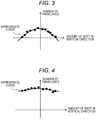
- an example of an image having difficulty in obtaining parallax is an image illustrating the distribution of the number of parallaxes as illustrated in FIG. 3 and includes an image captured on a wall with few feature points or in a dark environment in a garage or the like.
- an example of an image that is likely to have an error in parallax calculation is an image indicating the distribution of the number of parallaxes as illustrated in FIG. 4 and includes a captured image having many vertical patterns.
- optical axis deviation detection processing for detecting the amount of optical axis deviation between the first imaging unit 11 and the second imaging unit 12 will be described.
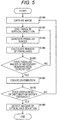
- FIG. 5 is a flowchart illustrating optical axis deviation detection processing.
- the first imaging unit 11 and the second imaging unit 12 perform imaging, and the image storage unit 13 stores a pair of images (first image and second image) captured at the same time (step S100).
- the moved image generation unit 14 generates (step S120) an image (third image) by vertically moving the pixels, by a predetermined amount, in one of the pair of images (first image and second image).
- an image third image
- a case of generating the third image from the first image captured by the first imaging unit 11 will be described as an example.
- the parallax image generation unit 15 generates a parallax image (first parallax image) from the first image and the second image stored in the image storage unit 13 and also generates a parallax image (second parallax image) from the other one (that is, the second image here) of the pair of images (first and second images) and from the third image (step S130). Note that calculation of the parallax value in the generation of the parallax image uses template matching.
- the optical axis deviation detection unit 16 calculates the number of parallaxes between the second image and each of the third images (step S140). Although the calculation of the number of parallaxes between the second image and the third image may use the entire image, here, it is assumed to calculate the number of parallaxes with higher reliability.
- the parallax with higher reliability means, for example, the parallax of a feature point having a high edge.
- step S150 it is determined whether the number of parallax images necessary for detecting the amount of optical axis deviation between the first imaging unit 11 and the second imaging unit 12 has been generated (step S150).
- various types of criteria can be conceived for determination of the number of parallax images necessary for detecting the amount of optical axis deviation, and now, for example, the number of parallax images in which an approximate curve obtained from the distribution of the number of parallaxes created in step S160 described below can achieve sufficient accuracy is to be empirically acquired to be set as a criterion.
- the processing in steps S120 to S140 is repeated until the determination result is YES.
- the moved image generation unit 14 generates a plurality of images (third images) by vertically moving the pixels, by a different predetermined amount for each of pixels, of one of the pair of images (first and second images)
- the parallax image generation unit 15 generates a parallax image (first parallax image) from the first image and the second image stored in the image storage unit 13 and also generates a plurality of parallax images (second parallax images) from the other one (that is, the second image here) of the pair of images (first and second images) and from the plurality of third images
- the optical axis deviation detection unit 16 calculates the number of parallaxes between the second image and the plurality of third images (steps S120 to S150) .
- step S150 the determination result in step S150 is YES
- the distribution of the number of parallaxes with respect to the amount of shift in the vertical direction in the third image is created (step S160).
- step S160 it is determined whether the usefulness of the distribution created in step S160 satisfies a criterion (that is, whether this is an image in which the distribution of the number of parallaxes is close to normal distribution and having large number of parallaxes) (step S170).
- step S170 the processing in steps S100 to S160 is repeated until an image in which the usefulness of the distribution satisfies the criterion is obtained.
- step S170 the determination result in step S170 is YES
- step S180 the amount of vertical optical axis deviation between the first imaging unit 11 and the second imaging unit 12 is detected (step S180) from the distribution of the number of parallaxes obtained in step S160, the processing is finished.
- the imaging device includes: the pair of imaging units including the first imaging unit 11 and second imaging unit 12; the image storage unit 13 for storing a first image captured by the first imaging unit 11 and a second image captured by the second imaging unit 12 at the same time as the first image; the moved image generation unit 14 for generating a third image by moving the pixels of the first image by a predetermined amount in the vertical direction; and a parallax image generation unit 15 for generating a first parallax image from the first image and the second image and generating a second parallax image from the second image and third image, and detects the amount of vertical optical axis deviation in the optical axis between the first imaging unit 11 and second imaging unit 12 on the basis of the first parallax image and second parallax image. Accordingly, it is possible to relax the limitation of the environment in which the calibration of the optical axis of the stereo camera can be performed, enabling implementation of calibration at any timing.
- the present invention is not limited to the above-described individual exemplary embodiments, but may include various types of modification.
- the above-described embodiments give detailed explanation just to allow the present invention to be clearly understood. Therefore, the present invention is not limited to the case having all of components in the configuration.
- each of the above-described configurations, functions, or the like may be implemented with software by a processor by interpreting and executing a program designed to realize individual functions.
Landscapes
- Engineering & Computer Science (AREA)
- Physics & Mathematics (AREA)
- General Physics & Mathematics (AREA)
- Remote Sensing (AREA)
- Computer Vision & Pattern Recognition (AREA)
- Theoretical Computer Science (AREA)
- Electromagnetism (AREA)
- Radar, Positioning & Navigation (AREA)
- Multimedia (AREA)
- Signal Processing (AREA)
- General Health & Medical Sciences (AREA)
- Biomedical Technology (AREA)
- Health & Medical Sciences (AREA)
- Measurement Of Optical Distance (AREA)
- Length Measuring Devices By Optical Means (AREA)
- Studio Devices (AREA)
Abstract
Description
- The present invention relates to an imaging device.
- In recent years, a driving support system using an image obtained by an in-vehicle camera device has attracted attention as one of the technologies contributing to safe driving and automatic driving. This system uses, for example, a technology that determines a deviation in the horizontal direction (parallax) with respect to a target object appearing in two images captured by an in-vehicle camera device having a pair of imaging devices (stereo cameras), and that calculates the distance to the target object using the principle of triangulation on the basis of the determined parallax.
- In the in-vehicle camera device used for such a technology, for example, the accuracy of the position of the optical axis of the lens would greatly affect the accuracy in the distance to be calculated and in the driving support system using the lens, and thus, adjustment of lens optical axis (calibration) is very important. Under this circumstance, various techniques related to the calibration of the optical axis in a stereo camera have been proposed. For example, PTL 1 (
JP 2013-113600 A - PTL 1:
JP 2013-113600 A - However, in the above-described known technology, the calibration board needs to be disposed at a predetermined position at implementation of calibration. Therefore, it has been difficult to perform calibration of the optical axis of the stereo camera during travel of the vehicle considered to have an influence of deterioration due to aging of hardware of the camera and a temperature change, which has resulted in a problem of significantly limited environment in which the calibration can be performed.
- The present invention has been made in view of the above, and aims to provide an imaging device capable of relaxing the limitation of the environment in which the calibration of the optical axis of the stereo camera can be performed.
- In order to achieve the above object, the present invention includes: a pair of imaging units including a first imaging unit and a second imaging unit; an image storage unit for storing a first image captured by the first imaging unit and a second image captured by the second imaging unit at the same time as the first image; a moved image generation unit for generating a third image by moving pixels of the first image by a predetermined amount in a vertical direction; a parallax image generation unit for generating a first parallax image from the first image and second image and generating a second parallax image from the second image and third image; and an optical axis deviation detection unit for detecting an amount of vertical optical axis deviation between the first imaging unit and the second imaging unit on the basis of the first parallax image and the second parallax image.
- According to the present invention, it is possible to relax the limitation of the environment in which the calibration of the optical axis of the stereo camera can be performed, enabling implementation of calibration at any timing.
-
- [
FIG. 1] FIG. 1 is a functional block diagram schematically illustrating an entire configuration of an imaging device according to the present embodiment. - [
FIG. 2] FIG. 2 is a diagram illustrating an example of a relationship between the amount of shift in the vertical direction in third images from the first image and the number of parallaxes of parallax images generated from each of the third images and a second image. - [
FIG. 3] FIG. 3 is a diagram illustrating an example of a relationship, in an image having difficulty in obtaining parallax, between the amount of shift in the vertical direction in the third image from the first image and the number of parallaxes of parallax images generated from each of the third images and the second image. - [
FIG. 4] FIG. 4 is a diagram illustrating an example of a relationship, in an image that is likely to have an error in parallax calculation, between the amount of shift in the vertical direction in the third image from the first image and the number of parallaxes of parallax images generated from each of the third images and the second image. - [
FIG. 5] FIG. 5 is a flowchart illustrating optical axis deviation detection processing. - Hereinafter, embodiments of the present invention will be described with reference to the drawings.
-
FIG. 1 is a functional block diagram schematically illustrating an entire configuration of an imaging device according to the present embodiment. - In
FIG. 1 , animaging device 1 generally includes a pair ofimaging units image storage unit 13, a movedimage generation unit 14, a parallaximage generation unit 15, an optical axisdeviation detection unit 16, and a unit for generating parallax image fordistance measurement 17, and adistance measurement unit 18. - The pair of
imaging units 11 and 12 (first imaging unit 11 and second imaging unit 12) constitute a stereo camera for capturing in the direction of an imaging target in theimaging device 1 to obtain an image, and is arranged at the same height on the left and right of theimaging device 1 such that the optical axis and imaging direction are oriented in the same direction. Each of thefirst imaging unit 11 and thesecond imaging unit 12 continuously captures images and outputs the captured images. - The
image storage unit 13 stores a pair of images (a first image and a second image) captured at the same time to be used for calculation of optical axis deviation among the images captured and continuously output by thefirst imaging unit 11 and thesecond imaging unit 12. - The moved
image generation unit 14 generates a plurality of images (third images) by vertically moving the pixels, by a different predetermined amount for each of pixels, in one of the pair of images (first image and second image) captured by theimaging units image storage unit 13. Here, an exemplary case of generating the plurality of third images from the first image captured by thefirst imaging unit 11 will be described. - The parallax
image generation unit 15 generates a parallax image (first parallax image) from the first image and the second image stored in theimage storage unit 13 and also generates a plurality of parallax images (second parallax images) from the other one (that is, the second image here) of the pair of images (first and second images) and from the plurality of third images. - The optical axis
deviation detection unit 16 detects the amount of optical axis deviation in the vertical direction between thefirst imaging unit 11 and thesecond imaging unit 12 on the basis of the first parallax image and the second parallax image. The amount of optical axis deviation detected by the optical axisdeviation detection unit 16 is transmitted to the unit for generating parallax image fordistance measurement 17 and to thedistance measurement unit 18. - The unit for generating parallax image for
distance measurement 17 generates a parallax image for distance measurement from the two images captured by the pair of imaging units, that is, thefirst imaging unit 11 and thesecond imaging unit 12. Note that generation of the parallax image by the unit for generating parallax image fordistance measurement 17 may use the amount of optical axis deviation detected by the optical axisdeviation detection unit 16. - The
distance measurement unit 18 measures a distance to a target object (for example, a pedestrian or another vehicle) appearing in the two images captured by the pair of imaging units (first imaging unit 11 and the second imaging unit 12) on the basis of the parallax image generated by the unit for generating parallax image fordistance measurement 17. Among various methods that can be considered as a measurement method, for example, the horizontal deviation (parallax) with respect to the target object appearing in two images captured by the pair of imaging units (first imaging unit 11 and second imaging unit 12) is determined by the parallax image, and the distance to the target object is calculated by the principle of triangulation on the basis of the determined parallax. Note that, when thedistance measurement unit 18 measures the distance, the measurement result is corrected using the optical axis deviation amount detected by the optical axisdeviation detection unit 16. - Here, the detection principle of the optical axis deviation amount will be described.
- For example, in two images captured by the pair of imaging units, the number of parallaxes of the parallax image obtained from the two images increases or decreases depending on the amount of vertical optical axis deviation in the pair of imaging units.
- That is, the number of parallaxes of the parallax image has a tendency to be a maximum value when there is no vertical optical axis deviation in the pair of imaging units (in a case where deviation is minimum), and decreases with an increase in the amount of optical axis deviation. The reason is that a search is performed with a matching direction of parallax image generation in the horizontal direction, and therefore, occurrence of vertical optical axis deviation in the pair of imaging units equals to degradation of the matching evaluation value. Accordingly, based on such a finding, the present inventors move one (first image, for example) of the two images (first and second images) captured by the pair of imaging units (first and
second imaging units 11 and 12) in the vertical direction (that is, generates the third image), and thereby changing the apparent amount of optical axis deviation in the optical axis of the pair of imaging units (thefirst imaging unit 11 and the second imaging unit 12), and then, calculates the amount of optical axis deviation in the pair of imaging units (first andsecond imaging units 11 and 12) on the basis of the state of change in the number of parallaxes of the parallax images obtained from the third images created by moving the first image in the vertical direction, and from the second image. -
FIG. 2 is a diagram illustrating an example of the relationship between the amounts of shift in the third image in the vertical direction from the first image and the number of parallaxes of the parallax images between each of the third images and the second image, in which the vertical axis represents the number of parallaxes of the parallax image, and the horizontal axis represents the amounts of shift in the vertical direction. - As illustrated in
FIG. 2 , the number of parallaxes of the parallax image changes in accordance with the change in the amount of shift in the vertical direction in the third image from the first image, that is, the change in the apparent amount of optical axis deviation in thefirst imaging unit 11 with respect to thesecond imaging unit 12. Here, since it is known that the number of parallaxes of the parallax image is the maximum value when there is no amount (minimum) of vertical optical axis deviation, it is possible to obtain the amount of vertical optical axis deviation between thefirst imaging unit 11 and thesecond imaging unit 12 from the difference between the origin position in the horizontal axis direction (that is, the amount of shift in the vertical direction in the third image), (that is, in a case where the third image is the same as the first image) and the value of the amount of shift at which the number of parallaxes is the maximum value. Note thatFIG. 2 indicates a case of calculating an approximate curve of the number of parallaxes (here, an upward-convex quadratic curve) using a method such as the least squares method, for example, so as to calculate the amount of deviation in the optical axis using this approximate curve. - Note that there is a need, in the calculation of the amount of optical axis deviation, to avoid use of an image having difficulty in obtaining parallax or an image that is likely to have an error in parallax calculation, as the image captured by the
first imaging unit 11 and thesecond imaging unit 12, in order to detect correct amount of optical axis deviation. That is, it is preferable to use, in the calculation of the amount of optical axis deviation, an image having the distribution of the number of parallaxes close to normal distribution and having large number of parallaxes, namely, an image in which the usefulness of the distribution of the number of parallaxes satisfies a criterion. Here, an example of an image having difficulty in obtaining parallax is an image illustrating the distribution of the number of parallaxes as illustrated inFIG. 3 and includes an image captured on a wall with few feature points or in a dark environment in a garage or the like. Meanwhile, an example of an image that is likely to have an error in parallax calculation is an image indicating the distribution of the number of parallaxes as illustrated inFIG. 4 and includes a captured image having many vertical patterns. In such an image, even when the pixels of the image are shifted in the vertical direction, the difference in the image (in particular, the difference in the vertical direction) is not observed before and after the shifting, and therefore leads to reduction in the change in the number of parallaxes due to the change in the amount of shift. - Next, optical axis deviation detection processing for detecting the amount of optical axis deviation between the
first imaging unit 11 and thesecond imaging unit 12 will be described. -
FIG. 5 is a flowchart illustrating optical axis deviation detection processing. - In
FIG. 5 , thefirst imaging unit 11 and thesecond imaging unit 12 perform imaging, and theimage storage unit 13 stores a pair of images (first image and second image) captured at the same time (step S100). - Subsequently, the moved
image generation unit 14 generates (step S120) an image (third image) by vertically moving the pixels, by a predetermined amount, in one of the pair of images (first image and second image). Here, a case of generating the third image from the first image captured by thefirst imaging unit 11 will be described as an example. - Subsequently, the parallax
image generation unit 15 generates a parallax image (first parallax image) from the first image and the second image stored in theimage storage unit 13 and also generates a parallax image (second parallax image) from the other one (that is, the second image here) of the pair of images (first and second images) and from the third image (step S130). Note that calculation of the parallax value in the generation of the parallax image uses template matching. - Subsequently, the optical axis
deviation detection unit 16 calculates the number of parallaxes between the second image and each of the third images (step S140). Although the calculation of the number of parallaxes between the second image and the third image may use the entire image, here, it is assumed to calculate the number of parallaxes with higher reliability. The parallax with higher reliability means, for example, the parallax of a feature point having a high edge. - Here, it is determined whether the number of parallax images necessary for detecting the amount of optical axis deviation between the
first imaging unit 11 and thesecond imaging unit 12 has been generated (step S150). Although various types of criteria can be conceived for determination of the number of parallax images necessary for detecting the amount of optical axis deviation, and now, for example, the number of parallax images in which an approximate curve obtained from the distribution of the number of parallaxes created in step S160 described below can achieve sufficient accuracy is to be empirically acquired to be set as a criterion. - In a case where the determination result in step S150 is NO, that is, where a sufficient number of parallax images have not been generated, the processing in steps S120 to S140 is repeated until the determination result is YES. With this processing, the moved
image generation unit 14 generates a plurality of images (third images) by vertically moving the pixels, by a different predetermined amount for each of pixels, of one of the pair of images (first and second images), the parallaximage generation unit 15 generates a parallax image (first parallax image) from the first image and the second image stored in theimage storage unit 13 and also generates a plurality of parallax images (second parallax images) from the other one (that is, the second image here) of the pair of images (first and second images) and from the plurality of third images, and the optical axisdeviation detection unit 16 calculates the number of parallaxes between the second image and the plurality of third images (steps S120 to S150) . - In a case where the determination result in step S150 is YES, the distribution of the number of parallaxes with respect to the amount of shift in the vertical direction in the third image is created (step S160).
- Subsequently, it is determined whether the usefulness of the distribution created in step S160 satisfies a criterion (that is, whether this is an image in which the distribution of the number of parallaxes is close to normal distribution and having large number of parallaxes) (step S170).
- In a case where the determination result in step S170 is NO, the processing in steps S100 to S160 is repeated until an image in which the usefulness of the distribution satisfies the criterion is obtained.
- In a case where the determination result in step S170 is YES, the amount of vertical optical axis deviation between the
first imaging unit 11 and thesecond imaging unit 12 is detected (step S180) from the distribution of the number of parallaxes obtained in step S160, the processing is finished. - Effects of the present embodiment having the above configuration will be described.
- In the conventional technology that acquires a plurality of images of a camera calibration board by using a plurality of cameras that captures a measurement target object to acquire images and that performs camera calibration using the plurality of images to calculate calibration parameters, it is necessary to place the calibration board in a predetermined position.
- Therefore, it has been difficult to perform calibration of the optical axis of the stereo camera during travel of the vehicle considered to have an influence of deterioration due to aging of hardware of the camera and a temperature change, which has resulted in a problem of significantly limited environment in which the calibration can be performed.
- In contrast, in the present embodiment, the imaging device includes: the pair of imaging units including the
first imaging unit 11 andsecond imaging unit 12; theimage storage unit 13 for storing a first image captured by thefirst imaging unit 11 and a second image captured by thesecond imaging unit 12 at the same time as the first image; the movedimage generation unit 14 for generating a third image by moving the pixels of the first image by a predetermined amount in the vertical direction; and a parallaximage generation unit 15 for generating a first parallax image from the first image and the second image and generating a second parallax image from the second image and third image, and detects the amount of vertical optical axis deviation in the optical axis between thefirst imaging unit 11 andsecond imaging unit 12 on the basis of the first parallax image and second parallax image. Accordingly, it is possible to relax the limitation of the environment in which the calibration of the optical axis of the stereo camera can be performed, enabling implementation of calibration at any timing. - The present invention is not limited to the above-described individual exemplary embodiments, but may include various types of modification. For example, the above-described embodiments give detailed explanation just to allow the present invention to be clearly understood. Therefore, the present invention is not limited to the case having all of components in the configuration.
- Moreover, the above configurations, functions, or the like, may be implemented by designing partial or entire portions with an integrated circuit, for example. Moreover, each of the above-described configurations, functions, or the like, may be implemented with software by a processor by interpreting and executing a program designed to realize individual functions.
-
- 1 imaging device
- 3 stereo
- 11 first imaging unit
- 12 second imaging unit
- 13 image storage unit
- 14 moved image generation unit
- 15 parallax image generation unit
- 16 optical axis deviation detection unit
- 17 unit for generating parallax image for distance measurement
- 18 distance measurement unit
Claims (6)
- An imaging device comprising:a pair of imaging units including a first imaging unit and a second imaging unit;an image storage unit for storing a first image captured by the first imaging unit and a second image captured by the second imaging unit at a same time as the first image;a moved image generation unit for generating a third image by moving pixels of the first image by a predetermined amount in a vertical direction;a parallax image generation unit for generating a first parallax image from the first image and the second image and generating a second parallax image from the second image and the third image; andan optical axis deviation detection unit for detecting an amount of vertical optical axis deviation between the first imaging unit and the second imaging unit on a basis of the first parallax image and the second parallax image.
- The imaging device according to claim 1,
wherein the moved image generation unit generates a plurality of the third images obtained by vertically moving the pixels, by a different amount for each of the pixels, in the first image,
the parallax image generation unit generates a plurality of the second parallax images from the second image and each of the plurality of third images, and
the optical axis deviation detection unit detects the amount of vertical optical axis deviation between the first imaging unit and the second imaging unit on a basis of the first parallax image and the plurality of second parallax images. - The imaging device according to claim 2,
wherein the optical axis deviation detection unit detects the optical axis deviation on a basis of distribution of an effective parallax in the first parallax image and distribution of an effective parallax of each of the plurality of second parallax images. - The imaging device according to claim 2,
wherein the optical axis deviation detection unit detects the amount of vertical optical axis deviation between the first imaging unit and the second imaging unit in a case where each of an effective parallax in the first parallax image and a maximum effective parallax of the plurality of second parallax images is greater than a predetermined threshold. - The imaging device according to claim 4,
wherein in a case where the effective parallax is below a threshold capable of detecting the optical axis deviation, the first image and the second image are changed to newly generate the first parallax image and the second parallax image to detect optical axis deviation. - The imaging device according to any one of claims 1 to 5, comprising:a unit for generating parallax image for distance measurement that generates a parallax image for distance measurement from two images captured by a pair of imaging units including the first imaging unit and the second imaging unit; anda distance measurement unit that measures a distance to a target object appearing in the two images captured by the pair of imaging units on a basis of the parallax image generated by the unit for generating parallax image for distance measurement,wherein at least one of the unit for generating parallax image for distance measurement or the distance measurement unit uses the amount of optical axis deviation detected by the optical axis deviation detection unit.
Applications Claiming Priority (2)
| Application Number | Priority Date | Filing Date | Title |
|---|---|---|---|
| JP2017124572 | 2017-06-26 | ||
| PCT/JP2018/020665 WO2019003771A1 (en) | 2017-06-26 | 2018-05-30 | Imaging device |
Publications (2)
| Publication Number | Publication Date |
|---|---|
| EP3647716A1 true EP3647716A1 (en) | 2020-05-06 |
| EP3647716A4 EP3647716A4 (en) | 2021-03-03 |
Family
ID=64742090
Family Applications (1)
| Application Number | Title | Priority Date | Filing Date |
|---|---|---|---|
| EP18823109.6A Pending EP3647716A4 (en) | 2017-06-26 | 2018-05-30 | IMAGING DEVICE |
Country Status (3)
| Country | Link |
|---|---|
| EP (1) | EP3647716A4 (en) |
| JP (1) | JP6867487B2 (en) |
| WO (1) | WO2019003771A1 (en) |
Families Citing this family (2)
| Publication number | Priority date | Publication date | Assignee | Title |
|---|---|---|---|---|
| JP7250211B2 (en) * | 2020-03-06 | 2023-03-31 | 日立Astemo株式会社 | processing equipment |
| CN113834428B (en) * | 2021-07-29 | 2024-05-14 | 阿里巴巴达摩院(杭州)科技有限公司 | Metal body thickness identification method, system, storage medium and electronic equipment |
Family Cites Families (12)
| Publication number | Priority date | Publication date | Assignee | Title |
|---|---|---|---|---|
| GB2338136B (en) * | 1995-02-22 | 2000-02-16 | Asahi Optical Co Ltd | Distance measuring apparatus |
| JP3617709B2 (en) * | 1995-11-10 | 2005-02-09 | 株式会社日本自動車部品総合研究所 | Distance measuring device |
| JP4956452B2 (en) * | 2008-01-25 | 2012-06-20 | 富士重工業株式会社 | Vehicle environment recognition device |
| JP5406768B2 (en) * | 2010-03-24 | 2014-02-05 | 富士フイルム株式会社 | Imaging apparatus and control method thereof |
| JP2012019399A (en) * | 2010-07-08 | 2012-01-26 | For-A Co Ltd | Stereoscopic image correction device, stereoscopic image correction method, and stereoscopic image correction system |
| JP5870510B2 (en) * | 2010-09-14 | 2016-03-01 | 株式会社リコー | Stereo camera device, calibration method and program |
| JP5693994B2 (en) * | 2011-02-16 | 2015-04-01 | 富士重工業株式会社 | Vehicle detection device |
| JP5792662B2 (en) * | 2011-03-23 | 2015-10-14 | シャープ株式会社 | Parallax calculation device, distance calculation device, and parallax calculation method |
| US8797387B2 (en) * | 2011-04-27 | 2014-08-05 | Aptina Imaging Corporation | Self calibrating stereo camera |
| JP2013113600A (en) | 2011-11-25 | 2013-06-10 | Sharp Corp | Stereo three-dimensional measuring apparatus |
| US8995719B2 (en) * | 2012-12-10 | 2015-03-31 | Intel Corporation | Techniques for improved image disparity estimation |
| JP6353289B2 (en) * | 2014-06-23 | 2018-07-04 | 株式会社Soken | Ranging correction device |
-
2018
- 2018-05-30 WO PCT/JP2018/020665 patent/WO2019003771A1/en not_active Ceased
- 2018-05-30 EP EP18823109.6A patent/EP3647716A4/en active Pending
- 2018-05-30 JP JP2019526718A patent/JP6867487B2/en active Active
Also Published As
| Publication number | Publication date |
|---|---|
| JPWO2019003771A1 (en) | 2020-02-27 |
| WO2019003771A1 (en) | 2019-01-03 |
| EP3647716A4 (en) | 2021-03-03 |
| JP6867487B2 (en) | 2021-04-28 |
Similar Documents
| Publication | Publication Date | Title |
|---|---|---|
| US10698308B2 (en) | Ranging method, automatic focusing method and device | |
| KR101259835B1 (en) | Apparatus and method for generating depth information | |
| EP2824417B1 (en) | Distance calculation device and distance calculation method | |
| KR101787304B1 (en) | Calibration method, calibration device, and computer program product | |
| JP6158779B2 (en) | Image processing device | |
| US10593053B2 (en) | Projection pattern creation apparatus and three-dimensional measuring apparatus | |
| US11509813B2 (en) | Image processing device | |
| JP6035774B2 (en) | Image processing apparatus, image processing method, and vehicle | |
| JPWO2020095549A1 (en) | Imaging device | |
| JP2016200557A (en) | Calibration device, distance measurement apparatus and calibration method | |
| EP3647716A1 (en) | Imaging device | |
| JP6395429B2 (en) | Image processing apparatus, control method thereof, and storage medium | |
| US20170064189A1 (en) | Imaging apparatus, focus position detection apparatus, and focus position detection method | |
| US10726528B2 (en) | Image processing apparatus and image processing method for image picked up by two cameras | |
| CN109313808A (en) | image processing system | |
| US20170223341A1 (en) | Vehicle-mounted stereo camera device and method for correcting the same | |
| CN106686373B (en) | Automatic focusing test system and method | |
| JP2014138331A (en) | Imaging apparatus and program | |
| US20200074659A1 (en) | Information processing apparatus, method thereof, and non-transitory computer-readable storage medium | |
| TW201413214A (en) | Optical detection system for inclination angle and laying position and detection method thereof | |
| JP6459487B2 (en) | Image processing apparatus, image processing method, and program | |
| JP2019211332A (en) | Information processing device, information processing method, and program | |
| JP7640656B1 (en) | Automatic focus detection method and device, photographing device, and storage medium | |
| JP2018112527A (en) | Distance measuring device, distance measuring method, and distance measuring program | |
| JPWO2018235256A1 (en) | Stereo measuring device and system |
Legal Events
| Date | Code | Title | Description |
|---|---|---|---|
| STAA | Information on the status of an ep patent application or granted ep patent |
Free format text: STATUS: THE INTERNATIONAL PUBLICATION HAS BEEN MADE |
|
| PUAI | Public reference made under article 153(3) epc to a published international application that has entered the european phase |
Free format text: ORIGINAL CODE: 0009012 |
|
| STAA | Information on the status of an ep patent application or granted ep patent |
Free format text: STATUS: REQUEST FOR EXAMINATION WAS MADE |
|
| 17P | Request for examination filed |
Effective date: 20191120 |
|
| AK | Designated contracting states |
Kind code of ref document: A1 Designated state(s): AL AT BE BG CH CY CZ DE DK EE ES FI FR GB GR HR HU IE IS IT LI LT LU LV MC MK MT NL NO PL PT RO RS SE SI SK SM TR |
|
| AX | Request for extension of the european patent |
Extension state: BA ME |
|
| DAV | Request for validation of the european patent (deleted) | ||
| DAX | Request for extension of the european patent (deleted) | ||
| A4 | Supplementary search report drawn up and despatched |
Effective date: 20210129 |
|
| RIC1 | Information provided on ipc code assigned before grant |
Ipc: H04N 5/225 20060101ALI20210125BHEP Ipc: H04N 17/00 20060101ALI20210125BHEP Ipc: G01C 3/06 20060101ALI20210125BHEP Ipc: G01C 3/00 20060101ALI20210125BHEP Ipc: G01B 11/245 20060101AFI20210125BHEP |
|
| RAP3 | Party data changed (applicant data changed or rights of an application transferred) |
Owner name: HITACHI ASTEMO, LTD. |
|
| STAA | Information on the status of an ep patent application or granted ep patent |
Free format text: STATUS: EXAMINATION IS IN PROGRESS |
|
| 17Q | First examination report despatched |
Effective date: 20241115 |
|
| RAP3 | Party data changed (applicant data changed or rights of an application transferred) |
Owner name: ASTEMO, LTD. |