EP3647676A1 - Heat exchanger for an air-conditioning system in particular of a motor vehicle - Google Patents
Heat exchanger for an air-conditioning system in particular of a motor vehicle Download PDFInfo
- Publication number
- EP3647676A1 EP3647676A1 EP18203077.5A EP18203077A EP3647676A1 EP 3647676 A1 EP3647676 A1 EP 3647676A1 EP 18203077 A EP18203077 A EP 18203077A EP 3647676 A1 EP3647676 A1 EP 3647676A1
- Authority
- EP
- European Patent Office
- Prior art keywords
- air
- longitudinal
- heat exchanger
- ptc
- distance
- Prior art date
- Legal status (The legal status is an assumption and is not a legal conclusion. Google has not performed a legal analysis and makes no representation as to the accuracy of the status listed.)
- Granted
Links
Images

Classifications
-
- F—MECHANICAL ENGINEERING; LIGHTING; HEATING; WEAPONS; BLASTING
- F24—HEATING; RANGES; VENTILATING
- F24H—FLUID HEATERS, e.g. WATER OR AIR HEATERS, HAVING HEAT-GENERATING MEANS, e.g. HEAT PUMPS, IN GENERAL
- F24H3/00—Air heaters
- F24H3/02—Air heaters with forced circulation
- F24H3/04—Air heaters with forced circulation the air being in direct contact with the heating medium, e.g. electric heating element
- F24H3/0405—Air heaters with forced circulation the air being in direct contact with the heating medium, e.g. electric heating element using electric energy supply, e.g. the heating medium being a resistive element; Heating by direct contact, i.e. with resistive elements, electrodes and fins being bonded together without additional element in-between
- F24H3/0429—For vehicles
-
- B—PERFORMING OPERATIONS; TRANSPORTING
- B60—VEHICLES IN GENERAL
- B60H—ARRANGEMENTS OF HEATING, COOLING, VENTILATING OR OTHER AIR-TREATING DEVICES SPECIALLY ADAPTED FOR PASSENGER OR GOODS SPACES OF VEHICLES
- B60H1/00—Heating, cooling or ventilating devices
- B60H1/22—Heating, cooling or ventilating devices the heat source being other than the propulsion plant
- B60H1/2215—Heating, cooling or ventilating devices the heat source being other than the propulsion plant the heat being derived from electric heaters
-
- F—MECHANICAL ENGINEERING; LIGHTING; HEATING; WEAPONS; BLASTING
- F24—HEATING; RANGES; VENTILATING
- F24H—FLUID HEATERS, e.g. WATER OR AIR HEATERS, HAVING HEAT-GENERATING MEANS, e.g. HEAT PUMPS, IN GENERAL
- F24H3/00—Air heaters
- F24H3/02—Air heaters with forced circulation
- F24H3/04—Air heaters with forced circulation the air being in direct contact with the heating medium, e.g. electric heating element
- F24H3/0405—Air heaters with forced circulation the air being in direct contact with the heating medium, e.g. electric heating element using electric energy supply, e.g. the heating medium being a resistive element; Heating by direct contact, i.e. with resistive elements, electrodes and fins being bonded together without additional element in-between
- F24H3/0429—For vehicles
- F24H3/0435—Structures comprising heat spreading elements in the form of fins
-
- F—MECHANICAL ENGINEERING; LIGHTING; HEATING; WEAPONS; BLASTING
- F24—HEATING; RANGES; VENTILATING
- F24H—FLUID HEATERS, e.g. WATER OR AIR HEATERS, HAVING HEAT-GENERATING MEANS, e.g. HEAT PUMPS, IN GENERAL
- F24H9/00—Details
- F24H9/18—Arrangement or mounting of grates or heating means
- F24H9/1854—Arrangement or mounting of grates or heating means for air heaters
- F24H9/1863—Arrangement or mounting of electric heating means
- F24H9/1872—PTC resistor
-
- H—ELECTRICITY
- H05—ELECTRIC TECHNIQUES NOT OTHERWISE PROVIDED FOR
- H05B—ELECTRIC HEATING; ELECTRIC LIGHT SOURCES NOT OTHERWISE PROVIDED FOR; CIRCUIT ARRANGEMENTS FOR ELECTRIC LIGHT SOURCES, IN GENERAL
- H05B3/00—Ohmic-resistance heating
- H05B3/40—Heating elements having the shape of rods or tubes
- H05B3/42—Heating elements having the shape of rods or tubes non-flexible
- H05B3/48—Heating elements having the shape of rods or tubes non-flexible heating conductor embedded in insulating material
- H05B3/50—Heating elements having the shape of rods or tubes non-flexible heating conductor embedded in insulating material heating conductor arranged in metal tubes, the radiating surface having heat-conducting fins
-
- B—PERFORMING OPERATIONS; TRANSPORTING
- B60—VEHICLES IN GENERAL
- B60H—ARRANGEMENTS OF HEATING, COOLING, VENTILATING OR OTHER AIR-TREATING DEVICES SPECIALLY ADAPTED FOR PASSENGER OR GOODS SPACES OF VEHICLES
- B60H1/00—Heating, cooling or ventilating devices
- B60H1/22—Heating, cooling or ventilating devices the heat source being other than the propulsion plant
- B60H2001/2268—Constructional features
-
- H—ELECTRICITY
- H05—ELECTRIC TECHNIQUES NOT OTHERWISE PROVIDED FOR
- H05B—ELECTRIC HEATING; ELECTRIC LIGHT SOURCES NOT OTHERWISE PROVIDED FOR; CIRCUIT ARRANGEMENTS FOR ELECTRIC LIGHT SOURCES, IN GENERAL
- H05B2203/00—Aspects relating to Ohmic resistive heating covered by group H05B3/00
- H05B2203/02—Heaters using heating elements having a positive temperature coefficient
-
- H—ELECTRICITY
- H05—ELECTRIC TECHNIQUES NOT OTHERWISE PROVIDED FOR
- H05B—ELECTRIC HEATING; ELECTRIC LIGHT SOURCES NOT OTHERWISE PROVIDED FOR; CIRCUIT ARRANGEMENTS FOR ELECTRIC LIGHT SOURCES, IN GENERAL
- H05B2203/00—Aspects relating to Ohmic resistive heating covered by group H05B3/00
- H05B2203/022—Heaters specially adapted for heating gaseous material
- H05B2203/023—Heaters of the type used for electrically heating the air blown in a vehicle compartment by the vehicle heating system
Definitions
- the invention relates to a heat exchanger for an air-conditioning system in particular of a motor vehicle.
- the invention furthermore, relates to an air-conditioning system having such a heat exchanger and to a motor vehicle having such an air-conditioning system.
- Electric PTC heating elements are employed in air-conditioning systems of motor vehicles in order to heat the air provided by the system.
- the PTC heating elements as part of a heat exchanger, are arranged in an air path arranged by the air to be heated, so that the heat generated by the PTC heating elements can be transferred to the air by thermal interaction.
- PTC heating elements are heating resistors, which with increasing temperature generate less heating output and thus also less heat.
- PTC heating elements are positive temperature coefficient thermistors.
- the basic idea of the invention is to place PTC heating elements of a heat exchanger in a heat exchanger nearer the air inlet than the air outlet of the air path conducted through the heat exchanger.
- Simulation calculations and experimental investigations have shown that in this way a more even heating of the air relative to air inlet and air outlet can be achieved compared with conventional heat exchangers with symmetrical arrangement of the PTC heating elements.
- Undesirable temporal fluctuations during the transmission of heat from the PTC heating elements to the air flowing through the air path can thus be prevented or - compared with conventional heat exchangers - significantly reduced.
- undesirable temporal temperature fluctuations in the air conducted through the heat exchanger are also minimised or even completely prevented.
- the heat exchanger according to the invention introduced here makes possible a homogeneous heating of air.
- a heat exchanger for an air-conditioning system, in particular of a motor vehicle, comprises multiple PTC heaters for heating the air conducted through the heat exchanger.
- the PTC heaters are arranged at a distance from one another so that the intermediate spaces that are present in each case between two adjacent PTC heaters form an air path through which the air can flow.
- At least one PTC heater comprises a tubular body with two longitudinal walls extending along a longitudinal direction, in which along the longitudinal direction a plurality of PTC heating elements is arranged next to one another. This is preferably true for all PTC heaters of the heat exchanger.
- the PTC heating elements are arranged at a shorter distance from a first longitudinal wall of the tubular body than from a second longitudinal wall located opposite the first longitudinal wall.
- the two first longitudinal walls of two adjacent tubular bodies delimit an air inlet for introducing the air into the air path formed between the two tubular bodies. Accordingly, the two second longitudinal walls of these two tubular bodies delimit an air outlet for discharging the air from this air path.
- This embodiment requires particularly little installation space.
- a first distance between the PTC heating elements and the first longitudinal wall measured perpendicularly to the longitudinal direction is shorter than a second distance between these PTC heating elements and the second longitudinal wall located opposite the first longitudinal wall measured perpendicularly to the longitudinal direction.
- the PTC heating elements can be particularly precisely positioned along the flow direction of the air path or intermediate space into the air path, so that the distance differential of the PTC heating elements from air inlet and air outlet characterising the invention - wherein the PTC heating elements are arranged nearer the air inlet than the air outlet - can be particularly precisely adjusted.
- the difference between the first and the second distance can be at least 2 mm.
- the first distance can be 0 mm to 2 mm and the second distance can be 2 to 4 mm.
- At least one PTC heating element comprises a heating ceramic which is arranged sandwich-like between two electrical contact plates for electrically connecting the heating ceramic to an electric voltage source.
- the heating ceramic is formed plate-like with a first and second heating ceramic longitudinal side.
- this embodiment is a particularly low construction.
- a rib structure is arranged in at least one intermediate space that is present between two adjacent PTC heaters, which extend along a transverse direction orthogonally to the longitudinal direction.
- the rib structure which can comprise a multiplicity of rib elements designed rib-like, the thermal connection between the PTC heating elements of the respective PTC heaters and the air flowing through the associated air path can be improved. This improves the efficiency of the heat exchanger.
- the rib structure projects over the two first longitudinal walls of the two tubular bodies delimiting the intermediate space along the transverse direction.
- Experimental investigations have shown that in this way a particularly homogeneous temporal temperature-controlling of the air can be achieved.
- the rib structure protrudes over the two first longitudinal walls along the transverse direction by up to maximally 4 mm.
- the rib structure terminates flush along the transverse direction with the two second longitudinal walls of the two tubular bodies delimiting the intermediate space.
- the PTC heaters are stacked on top of one another along a stacking direction, which extends perpendicularly both regarding the longitudinal and also transverse direction.
- the respective rib structure that is present in the intermediate space between two adjacent PTC heaters supports itself on the two tubular bodies which are adjacent along the stacking direction.
- Such a stack-like construction allows the heating of air which is suitably conducted through a plurality of air paths.
- the invention also relates to an air-conditioning system having a heat exchanger introduced above.
- the advantages of the heat exchanger according to the invention explained above can thus also be transferred to the air-conditioning system according to the invention.
- the invention finally relates to a motor vehicle having an air-conditioning system explained above.
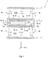
- Figure 1 shows exemplarily a PTC heater 2 of a heat exchanger 1 according to the invention, which can be employed in an air-conditioning system (not shown) of a motor vehicle, in a sectional representation.
- the heat exchanger 1 comprises multiple PTC heaters 2 for heating the air L S conducted through the heat exchanger, which are arranged at a distance from one another and are stacked on top of one another along a stacking direction S, so that the respective intermediate spaces 3 that are present between two adjacent PTC heaters form an air path 10 through which the air L S can flow.
- a rib structure 4 each can be arranged, which is only roughly schematically indicated in Figure 1 .
- the PTC heater 2 comprises a tubular body 5 with two longitudinal walls 8a, 8b extending along a longitudinal direction L. These two longitudinal walls 8a, 8b are referred to as first and second longitudinal wall 8a, 8b in the following, lie, in the cross section shown in Figure 1 , opposite one another perpendicularly to the longitudinal direction L and in this cross section form narrow sides 18 of the tubular body 5.
- the tubular body with the four longitudinal walls 8a - 8d has the geometry of a rectangle with two narrow sides 18 and two broad sides 19.
- the longitudinal direction L in this case extends orthogonally to the stacking direction S.
- the tubular body 5 with the longitudinal walls 8a - 8d delimits a tubular body interior 6, in which the longitudinal direction L multiple PTC heating elements 7 are arranged next to one another and at a distance from one another.
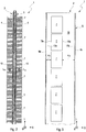
- Figure 2 shows the tubular body 5 of the PTC heater 2 in a longitudinal section along the longitudinal direction L
- Figure 3 a plan view of an inner side 16 of the tubular body 5 in a greatly simplified representation.
- six PTC heating elements 7 are exemplarily shown.
- the PTC heating elements 7 are arranged at a shorter distance from a first longitudinal wall 8a of the tubular body 5 than from the second longitudinal wall 8b located opposite the first longitudinal wall 8a.
- a first distance a1 measured along the transverse direction Q and thus perpendicularly to the longitudinal direction L between the PTC heating elements 7 and the first longitudinal wall 8a of the tubular body 5 is thus shorter than a distance a2 likewise measured perpendicularly to the longitudinal direction L between these PTC heating elements 7 and the second longitudinal wall 8b of the same tubular body 5, which is located opposite the first longitudinal wall 8a.
- the difference D between the first distance a1 and the second distance a2 amounts to at least 2 mm; alternatively or additionally, the first distance a1 can amount to 0 mm to 2 mm and the second distance at least 2 mm to 4 mm.
- the PTC heating element 7 arranged in the respective tubular body interior 6 comprises a heating ceramic 11, which is arranged sandwich-like between two electrical contact plates 12a, 12b.
- the two electrical contact plates 12a, 12b are formed so as to be electrically conductive and serve for electrically connecting the heating ceramic 11 to an electric voltage source.
- the two electrical contact plates 12a, 12b preferably consist of a metal or another suitable electrically conductive material. Since the material of the tubular body 5 is typically likewise a metal, i.e.
- an electrically conductive material preferably a single layer or multilayer insulation
- an electrical insulation 13 is provided between the two electrical contact plates 12a, 12b, which can comprise two electrically insulating insulation layers 14a, 14b of an electrically insulating material, preferably a plastic.
- a first insulation layer 14a is arranged between a first electrical contact plate 12a and a third longitudinal wall 8c of the tubular body 5, which connects the first and the second longitudinal wall 8a, 8b with one another.
- a second insulation layer 14b is arranged between a second electrical contact plate 12b and a fourth longitudinal wall 8c of the tubular body 5, which likewise connects the first and the second longitudinal wall 8a, 8b with one another and is located opposite the third longitudinal wall 8c.
- the heating ceramic 11 is also formed plate-like and has a first and a second heating ceramic longitudinal side 15a, 15b.
- the first or second distance a1, a2 of the PTC heating element 11 explained above from the first and second longitudinal wall 8a, 8b of the tubular body 5 is fixed or measured with respect to the first or second heating ceramic longitudinal side 15a, 15b and an inner side 17a, 17b.
- the two first longitudinal walls 8a of two adjacent tubular bodies 5 delimit an air inlet 9a for introducing the air L S into the air path 10 formed between the two tubular bodies 5, which extends along a transverse direction Q running orthogonally to the longitudinal direction L S . Accordingly, the two second longitudinal walls 8b of these two tubular bodies 5 delimit an air outlet 9b for discharging the air from this intermediate space 3 or air path 10.
- the rib structures 4 shown in the Figures 1 and 2 each of which is arranged in the intermediate space 3 that is present between two adjacent PTC heaters 2, extends along the transverse direction Q, which runs orthogonally to the longitudinal direction L.
- the stacking direction S, the longitudinal direction L and the transverse direction Q thus each extend perpendicularly to one another.
- the rib structure 4 supports itself on the two tubular bodies 5 that are adjacent along the stacking direction and can be (soldered or) bonded to these.
- the tubular body 5 can protrude over the adjacent rib structures in the cross section that is perpendicular to the longitudinal direction L.
- the rib structure 4 can protrude in the cross section perpendicularly to the longitudinal direction L along the transverse direction Q over the two first longitudinal walls 8a, 8b of the two tubular bodies 5 delimiting the intermediate space 3.
- the rib structure 4 protrudes along the transverse direction Q by maximally 4 mm over the two first longitudinal walls 8a, 8b.
- the rib structure 4 - this is likewise shown in Figure 4 - can terminate flush with the two longitudinal walls 8a, 8b of these two tubular bodies 5 along the transverse direction Q.
Landscapes
- Engineering & Computer Science (AREA)
- Physics & Mathematics (AREA)
- Thermal Sciences (AREA)
- Mechanical Engineering (AREA)
- Chemical & Material Sciences (AREA)
- Combustion & Propulsion (AREA)
- General Engineering & Computer Science (AREA)
- Air-Conditioning For Vehicles (AREA)
Abstract
Description
- The invention relates to a heat exchanger for an air-conditioning system in particular of a motor vehicle. The invention, furthermore, relates to an air-conditioning system having such a heat exchanger and to a motor vehicle having such an air-conditioning system.
- Electric PTC heating elements are employed in air-conditioning systems of motor vehicles in order to heat the air provided by the system. For this purpose, the PTC heating elements, as part of a heat exchanger, are arranged in an air path arranged by the air to be heated, so that the heat generated by the PTC heating elements can be transferred to the air by thermal interaction.
- Said PTC heating elements are heating resistors, which with increasing temperature generate less heating output and thus also less heat. Thus, PTC heating elements are positive temperature coefficient thermistors.
- Here it proves to be problematic that at too high a temperature of the air conducted past a PTC heating element, insufficient heat can be dissipated from the PTC heating element. In this case, the temperature of the PTC heating element increases as a result of which in turn the power output of the PTC heating element can consequently drop significantly. This in turn leads to an at least temporarily insufficient heating of the air.
- It is an object of the present invention to create an improved embodiment for a heat exchanger, with which the problem explained above, is at least partly - ideally even completely - eliminated.
- This object is solved through the subject of the independent patent claims. Preferred embodiments are subject of the dependent patent claims.
- Accordingly, the basic idea of the invention is to place PTC heating elements of a heat exchanger in a heat exchanger nearer the air inlet than the air outlet of the air path conducted through the heat exchanger. Simulation calculations and experimental investigations have shown that in this way a more even heating of the air relative to air inlet and air outlet can be achieved compared with conventional heat exchangers with symmetrical arrangement of the PTC heating elements. Undesirable temporal fluctuations during the transmission of heat from the PTC heating elements to the air flowing through the air path can thus be prevented or - compared with conventional heat exchangers - significantly reduced. As a consequence, undesirable temporal temperature fluctuations in the air conducted through the heat exchanger are also minimised or even completely prevented. In the result, the heat exchanger according to the invention introduced here makes possible a homogeneous heating of air.
- A heat exchanger according to the invention for an air-conditioning system, in particular of a motor vehicle, comprises multiple PTC heaters for heating the air conducted through the heat exchanger. The PTC heaters are arranged at a distance from one another so that the intermediate spaces that are present in each case between two adjacent PTC heaters form an air path through which the air can flow. At least one PTC heater comprises a tubular body with two longitudinal walls extending along a longitudinal direction, in which along the longitudinal direction a plurality of PTC heating elements is arranged next to one another. This is preferably true for all PTC heaters of the heat exchanger. According to the invention, the PTC heating elements are arranged at a shorter distance from a first longitudinal wall of the tubular body than from a second longitudinal wall located opposite the first longitudinal wall.
- According to a preferred embodiment, the two first longitudinal walls of two adjacent tubular bodies delimit an air inlet for introducing the air into the air path formed between the two tubular bodies. Accordingly, the two second longitudinal walls of these two tubular bodies delimit an air outlet for discharging the air from this air path. This embodiment requires particularly little installation space.
- According to a further preferred embodiment, a first distance between the PTC heating elements and the first longitudinal wall measured perpendicularly to the longitudinal direction is shorter than a second distance between these PTC heating elements and the second longitudinal wall located opposite the first longitudinal wall measured perpendicularly to the longitudinal direction. With this embodiment, the PTC heating elements can be particularly precisely positioned along the flow direction of the air path or intermediate space into the air path, so that the distance differential of the PTC heating elements from air inlet and air outlet characterising the invention - wherein the PTC heating elements are arranged nearer the air inlet than the air outlet - can be particularly precisely adjusted.
- Practically, the difference between the first and the second distance can be at least 2 mm. Alternatively or additionally, the first distance can be 0 mm to 2 mm and the second distance can be 2 to 4 mm.
- Particularly preferably, at least one PTC heating element comprises a heating ceramic which is arranged sandwich-like between two electrical contact plates for electrically connecting the heating ceramic to an electric voltage source. In this version, the heating ceramic is formed plate-like with a first and second heating ceramic longitudinal side. Thus, the distance of the heating element from the first and second longitudinal wall of the body that is substantial for the invention can be fixed or measured with respect to the first or second heating ceramic longitudinal side. In addition, this embodiment is a particularly low construction.
- According to an advantageous further development, a rib structure is arranged in at least one intermediate space that is present between two adjacent PTC heaters, which extend along a transverse direction orthogonally to the longitudinal direction. By means of the rib structure, which can comprise a multiplicity of rib elements designed rib-like, the thermal connection between the PTC heating elements of the respective PTC heaters and the air flowing through the associated air path can be improved. This improves the efficiency of the heat exchanger.
- In this further development, the rib structure projects over the two first longitudinal walls of the two tubular bodies delimiting the intermediate space along the transverse direction. Experimental investigations have shown that in this way a particularly homogeneous temporal temperature-controlling of the air can be achieved. Particularly practically, the rib structure protrudes over the two first longitudinal walls along the transverse direction by up to maximally 4 mm.
- In another advantageous further development, the rib structure terminates flush along the transverse direction with the two second longitudinal walls of the two tubular bodies delimiting the intermediate space.
- Practically, the PTC heaters are stacked on top of one another along a stacking direction, which extends perpendicularly both regarding the longitudinal and also transverse direction. Here, the respective rib structure that is present in the intermediate space between two adjacent PTC heaters supports itself on the two tubular bodies which are adjacent along the stacking direction. Such a stack-like construction allows the heating of air which is suitably conducted through a plurality of air paths.
- The invention also relates to an air-conditioning system having a heat exchanger introduced above. The advantages of the heat exchanger according to the invention explained above can thus also be transferred to the air-conditioning system according to the invention.
- The invention finally relates to a motor vehicle having an air-conditioning system explained above.
- Further important features and advantages of the invention are obtained from the subclaims, from the drawings and from the associated figure description by way of the drawings.
- Preferred exemplary embodiments of the invention are shown in the drawings and are explained in more detail in the following description, wherein same reference characters relate to same or similar or functionally same components.
- It is to be understood that the features mentioned above and still to be explained in the following cannot only be used in the respective combination stated but also in other combinations or by themselves without leaving the scope of the present invention.
- It shows, in each case schematically:
- Fig. 1
- a PTC heater of a heat exchanger according to the invention in across section,
- Fig. 2
- the PTC heater of
Figure 1 in a longitudinal section, - Fig. 3
- the PTC heater of
Figure 1 in a a longitudinal section through the PTC ceramic, - Fig. 4
- a version of the PTC heater of
Figure 1 . -
Figure 1 shows exemplarily aPTC heater 2 of aheat exchanger 1 according to the invention, which can be employed in an air-conditioning system (not shown) of a motor vehicle, in a sectional representation. - Accordingly, the
heat exchanger 1 comprisesmultiple PTC heaters 2 for heating the air LS conducted through the heat exchanger, which are arranged at a distance from one another and are stacked on top of one another along a stacking direction S, so that the respectiveintermediate spaces 3 that are present between two adjacent PTC heaters form anair path 10 through which the air LS can flow. In the intermediate spaces 3 arib structure 4 each can be arranged, which is only roughly schematically indicated inFigure 1 . - In
Figure 1 , only asingle PTC heater 2 with theintermediate spaces 3 which are adjacent in the stacking direction S is completely shown for the sake of clarity. ThePTC heater 2 comprises atubular body 5 with twolongitudinal walls longitudinal walls longitudinal wall Figure 1 , opposite one another perpendicularly to the longitudinal direction L and in this cross section formnarrow sides 18 of thetubular body 5. Two furtherlongitudinal walls tubular body 5, which likewise lie opposite one another in the cross section ofFigure 1 and are arranged perpendicularly to the first and secondlongitudinal wall broad sides 19 of thetubular body 5 and complete the first and secondlongitudinal wall tubular body 5. In the cross section ofFigure 1 , the tubular body with the fourlongitudinal walls 8a - 8d has the geometry of a rectangle with twonarrow sides 18 and twobroad sides 19. The longitudinal direction L in this case extends orthogonally to the stacking direction S. Thetubular body 5 with thelongitudinal walls 8a - 8d delimits atubular body interior 6, in which the longitudinal direction L multiplePTC heating elements 7 are arranged next to one another and at a distance from one another. -
Figure 2 shows thetubular body 5 of thePTC heater 2 in a longitudinal section along the longitudinal direction L,Figure 3 a plan view of aninner side 16 of thetubular body 5 in a greatly simplified representation. InFigures 2 and 3 , sixPTC heating elements 7 are exemplarily shown. - From both
Figure 1 and alsoFigure 3 it is evident that thePTC heating elements 7 are arranged at a shorter distance from a firstlongitudinal wall 8a of thetubular body 5 than from the secondlongitudinal wall 8b located opposite the firstlongitudinal wall 8a. A first distance a1 measured along the transverse direction Q and thus perpendicularly to the longitudinal direction L between thePTC heating elements 7 and the firstlongitudinal wall 8a of thetubular body 5 is thus shorter than a distance a2 likewise measured perpendicularly to the longitudinal direction L between thesePTC heating elements 7 and the secondlongitudinal wall 8b of the sametubular body 5, which is located opposite the firstlongitudinal wall 8a. - In the exemplary scenario, the difference D between the first distance a1 and the second distance a2 amounts to at least 2 mm; alternatively or additionally, the first distance a1 can amount to 0 mm to 2 mm and the second distance at least 2 mm to 4 mm.
- According to
Figure 1 , thePTC heating element 7 arranged in the respectivetubular body interior 6 comprises aheating ceramic 11, which is arranged sandwich-like between twoelectrical contact plates electrical contact plates heating ceramic 11 to an electric voltage source. The twoelectrical contact plates tubular body 5 is typically likewise a metal, i.e. an electrically conductive material, an electrical insulation 13, preferably a single layer or multilayer insulation, is provided between the twoelectrical contact plates electrical contact plate 12a and a thirdlongitudinal wall 8c of thetubular body 5, which connects the first and the secondlongitudinal wall electrical contact plate 12b and a fourthlongitudinal wall 8c of thetubular body 5, which likewise connects the first and the secondlongitudinal wall longitudinal wall 8c. Theheating ceramic 11 is also formed plate-like and has a first and a second heating ceramiclongitudinal side PTC heating element 11 explained above from the first and secondlongitudinal wall tubular body 5 is fixed or measured with respect to the first or second heating ceramiclongitudinal side inner side - The two first
longitudinal walls 8a of two adjacenttubular bodies 5 delimit anair inlet 9a for introducing the air LS into theair path 10 formed between the twotubular bodies 5, which extends along a transverse direction Q running orthogonally to the longitudinal direction LS. Accordingly, the two secondlongitudinal walls 8b of these twotubular bodies 5 delimit anair outlet 9b for discharging the air from thisintermediate space 3 orair path 10. - The
rib structures 4 shown in theFigures 1 and2 , each of which is arranged in theintermediate space 3 that is present between twoadjacent PTC heaters 2, extends along the transverse direction Q, which runs orthogonally to the longitudinal direction L. The stacking direction S, the longitudinal direction L and the transverse direction Q thus each extend perpendicularly to one another. Therib structure 4 supports itself on the twotubular bodies 5 that are adjacent along the stacking direction and can be (soldered or) bonded to these. - As shown in
Figure 1 , thetubular body 5 can protrude over the adjacent rib structures in the cross section that is perpendicular to the longitudinal direction L. - However a version of the example of
Figure 1 shown inFigure 4 is also conceivable. Accordingly, therib structure 4 can protrude in the cross section perpendicularly to the longitudinal direction L along the transverse direction Q over the two firstlongitudinal walls tubular bodies 5 delimiting theintermediate space 3. In this case it proves to be advantageous if therib structure 4 protrudes along the transverse direction Q by maximally 4 mm over the two firstlongitudinal walls Figure 4 - can terminate flush with the twolongitudinal walls tubular bodies 5 along the transverse direction Q.
Claims (12)
- A heat exchanger (1) for an air-conditioning system, in particular of a motor vehicle,- having multiple PTC heaters (2) for heating the air (LS) conducted through the heat exchangers (1), which are arranged at a distance from one another, so that the respective intermediate spaces (3) that are present between two adjacent PTC heaters (2) in each case form an air path (10) through which the air (LS) can flow,- wherein at least one PTC heater (2) comprises a tubular body (5) with two longitudinal walls (8a, 8b) which extend along a longitudinal direction (L), in which along the longitudinal direction (L) a plurality of PTC heating elements (7) is arranged next to one another,- wherein the PTC heating elements (7) are arranged at a shorter distance (a1) from a first longitudinal wall (8a) of the tubular body (5) than a second longitudinal wall (8b) located opposite the first longitudinal wall (8a).
- The heat exchanger according to Claim 1,
characterized in that- the two first longitudinal walls (8a) of two adjacent tubular bodies (5) delimit an air inlet (9a) for introducing the air (LS) into the air path (10) formed between the two tubular bodies (5); and in that- the two second longitudinal walls (8a, 8b) of these two tubular bodies (5) delimit an air outlet (9b) for discharging the air (LS) from this air path (10). - The heat exchanger according to Claim 1 or 2,
characterized in that
a first distance (a1) measured perpendicularly to the longitudinal direction (L) between the PTC heating elements (7) and the first longitudinal wall (8a) is shorter than a second distance (a2) measured perpendicularly to the longitudinal direction (L) between these PTC heating elements (7) and the second longitudinal wall (8b) located opposite the first longitudinal wall (8a). - The heat exchanger according to Claim 3,
characterized in that
a difference (D) between the first and the second distance (a1, a2) amounts to at least 2 mm; or/and in that
the first distance (a1) amounts to maximally 5 mm and the second distance amounts to at least 2 mm (a2). - The heat exchanger according to any one of the preceding claims, characterized in that- at least one PTC heating element (7) comprises a heating ceramic (11), which is arranged sandwich-like between two electrical contact plates (12a, 12b) for electrically connecting the PTC heating ceramic (11) with an electric voltage source,- the PTC heating ceramic (11) is formed plate-like with a first and second heating ceramic longitudinal side (15a, 15b),- the first or second distance (a1, a2) of the PTC heating element (7) from the first and second longitudinal wall (8a, 8b) of the tubular body (5) is fixed or measured with respect to the first or second heating ceramic longitudinal side (15a, 15b).
- The heat exchanger according to any one of the preceding claims,
characterized in that- in at least one intermediate space (3) that is present between two adjacent PTC heaters (2) a rib structure (4) is arranged, which extends along a transverse direction orthogonally to the longitudinal direction. - The heat exchanger according to Claim 6,
characterized in that
the rib structure (4) protrudes over the first longitudinal walls (9a, 9b) of the two tubular bodies (5) delimiting the intermediate space (3) along the transverse direction (Q). - The heat exchanger according to Claim 6 or 7,
characterized in that
the rib structure (4) protrudes along the transverse direction (Q) by maximally 4 mm over the first two longitudinal walls (9a, 9b). - The heat exchanger according to any one of the Claims 6 to 8,
characterized in that
the rib structure (4) terminates flush along the transverse direction (Q) with the two second longitudinal walls (9a, 9b) of the two tubular bodies (5) delimiting the interior space (3). - The heat exchanger according to any one of the preceding claims,
characterized in that- the multiple PTC heaters (2) are stacked on top of one another along a stacking direction (S) which extends perpendicularly both to the longitudinal and also transverse direction (L, Q),- the rib structure (4) supports itself on the two tubular bodies (5) which are adjacent along the stacking direction (S). - An air-conditioning system having a heat exchanger (1) according to any one of the preceding claims.
- A motor vehicle having an air-conditioning system according to Claim 11.
Priority Applications (1)
| Application Number | Priority Date | Filing Date | Title |
|---|---|---|---|
| EP18203077.5A EP3647676B1 (en) | 2018-10-29 | 2018-10-29 | Heat exchanger for an air-conditioning system in particular of a motor vehicle |
Applications Claiming Priority (1)
| Application Number | Priority Date | Filing Date | Title |
|---|---|---|---|
| EP18203077.5A EP3647676B1 (en) | 2018-10-29 | 2018-10-29 | Heat exchanger for an air-conditioning system in particular of a motor vehicle |
Publications (2)
| Publication Number | Publication Date |
|---|---|
| EP3647676A1 true EP3647676A1 (en) | 2020-05-06 |
| EP3647676B1 EP3647676B1 (en) | 2023-03-08 |
Family
ID=64082933
Family Applications (1)
| Application Number | Title | Priority Date | Filing Date |
|---|---|---|---|
| EP18203077.5A Active EP3647676B1 (en) | 2018-10-29 | 2018-10-29 | Heat exchanger for an air-conditioning system in particular of a motor vehicle |
Country Status (1)
| Country | Link |
|---|---|
| EP (1) | EP3647676B1 (en) |
Cited By (1)
| Publication number | Priority date | Publication date | Assignee | Title |
|---|---|---|---|---|
| EP3930423A1 (en) * | 2020-06-22 | 2021-12-29 | Mahle International GmbH | Heating module for a heating device |
Citations (3)
| Publication number | Priority date | Publication date | Assignee | Title |
|---|---|---|---|---|
| FR2793546A1 (en) * | 1999-05-14 | 2000-11-17 | Valeo Climatisation | Heat exchanger combining water/air heating and electric heating for interior heating of motor vehicles comprises stack of heating elements separated by interval delimited by thin corrugated plates |
| EP1545157A2 (en) * | 2003-12-20 | 2005-06-22 | Eichenauer Heizelemente GmbH & Co.KG | Tube and process for compression-fitting of fuctional elements in such a tube |
| EP2053902A1 (en) * | 2007-10-26 | 2009-04-29 | Calsonic Kansei Corporation | Electrical heating apparatus, method of manufacturing heat generator unit and pressing jig for use in manufacturing thereof |
-
2018
- 2018-10-29 EP EP18203077.5A patent/EP3647676B1/en active Active
Patent Citations (3)
| Publication number | Priority date | Publication date | Assignee | Title |
|---|---|---|---|---|
| FR2793546A1 (en) * | 1999-05-14 | 2000-11-17 | Valeo Climatisation | Heat exchanger combining water/air heating and electric heating for interior heating of motor vehicles comprises stack of heating elements separated by interval delimited by thin corrugated plates |
| EP1545157A2 (en) * | 2003-12-20 | 2005-06-22 | Eichenauer Heizelemente GmbH & Co.KG | Tube and process for compression-fitting of fuctional elements in such a tube |
| EP2053902A1 (en) * | 2007-10-26 | 2009-04-29 | Calsonic Kansei Corporation | Electrical heating apparatus, method of manufacturing heat generator unit and pressing jig for use in manufacturing thereof |
Cited By (3)
| Publication number | Priority date | Publication date | Assignee | Title |
|---|---|---|---|---|
| EP3930423A1 (en) * | 2020-06-22 | 2021-12-29 | Mahle International GmbH | Heating module for a heating device |
| CN113905470A (en) * | 2020-06-22 | 2022-01-07 | 马勒国际有限公司 | Heating module for a heating device |
| CN113905470B (en) * | 2020-06-22 | 2024-11-12 | 马勒国际有限公司 | Heating modules for heating devices |
Also Published As
| Publication number | Publication date |
|---|---|
| EP3647676B1 (en) | 2023-03-08 |
Similar Documents
| Publication | Publication Date | Title |
|---|---|---|
| US6720536B2 (en) | Electric heating device | |
| US20150163863A1 (en) | Electrical heating system for a motor vehicle | |
| US20130188937A1 (en) | Heat medium heating apparatus and vehicle air-conditioning apparatus provided with the same | |
| US20130243411A1 (en) | Heat medium heating unit and vehicle air conditioning apparatus provided with the same | |
| CN112822808B (en) | Heating module | |
| US11835303B2 (en) | Heat transfer device for tempering batteries and components of the power electronics | |
| CN110418438B (en) | Temperature control device with PTC module | |
| KR102030200B1 (en) | Insulated heating module for a supplemental heating device | |
| CN104748201B (en) | Ptc heater | |
| EP3647676B1 (en) | Heat exchanger for an air-conditioning system in particular of a motor vehicle | |
| US20250172319A1 (en) | An electrical fluid heater | |
| CN116772404A (en) | Heat exchanger, coolant heater and method of forming a heat exchanger body | |
| CN104823004B (en) | It is heat sink, associated for thermal modules and corresponding assemble method | |
| EP3401617A1 (en) | Electric heater | |
| CN115768638A (en) | Electric fluid heater | |
| US20210144810A1 (en) | Ptc heating element and a ptc heating module | |
| US20220266659A1 (en) | Heater for heating a heat transfer medium, especially in a vehicle | |
| CN103884092B (en) | Vehicle heater and its manufacture method | |
| WO2023117598A1 (en) | An electrical fluid heater | |
| DE102018209777A1 (en) | PTC heating module | |
| US10964460B2 (en) | PTC thermistor module | |
| CN112492708A (en) | PTC heating device | |
| JP2021015687A (en) | Liquid-fluid heating device and method for manufacturing the same | |
| EP3296660A1 (en) | Electric heater | |
| CN121866170A (en) | Electrothermal heater |
Legal Events
| Date | Code | Title | Description |
|---|---|---|---|
| PUAI | Public reference made under article 153(3) epc to a published international application that has entered the european phase |
Free format text: ORIGINAL CODE: 0009012 |
|
| STAA | Information on the status of an ep patent application or granted ep patent |
Free format text: STATUS: THE APPLICATION HAS BEEN PUBLISHED |
|
| AK | Designated contracting states |
Kind code of ref document: A1 Designated state(s): AL AT BE BG CH CY CZ DE DK EE ES FI FR GB GR HR HU IE IS IT LI LT LU LV MC MK MT NL NO PL PT RO RS SE SI SK SM TR |
|
| AX | Request for extension of the european patent |
Extension state: BA ME |
|
| STAA | Information on the status of an ep patent application or granted ep patent |
Free format text: STATUS: REQUEST FOR EXAMINATION WAS MADE |
|
| 17P | Request for examination filed |
Effective date: 20200813 |
|
| RBV | Designated contracting states (corrected) |
Designated state(s): AL AT BE BG CH CY CZ DE DK EE ES FI FR GB GR HR HU IE IS IT LI LT LU LV MC MK MT NL NO PL PT RO RS SE SI SK SM TR |
|
| REG | Reference to a national code |
Ref country code: DE Ref legal event code: R079 Ref document number: 602018046909 Country of ref document: DE Free format text: PREVIOUS MAIN CLASS: F24H0003040000 Ipc: F24H0009186300 |
|
| GRAP | Despatch of communication of intention to grant a patent |
Free format text: ORIGINAL CODE: EPIDOSNIGR1 |
|
| STAA | Information on the status of an ep patent application or granted ep patent |
Free format text: STATUS: GRANT OF PATENT IS INTENDED |
|
| RIC1 | Information provided on ipc code assigned before grant |
Ipc: B60H 1/22 20060101ALI20220930BHEP Ipc: H05B 3/50 20060101ALI20220930BHEP Ipc: F24H 3/04 20060101ALI20220930BHEP Ipc: F24H 9/1863 20220101AFI20220930BHEP |
|
| INTG | Intention to grant announced |
Effective date: 20221103 |
|
| GRAS | Grant fee paid |
Free format text: ORIGINAL CODE: EPIDOSNIGR3 |
|
| GRAA | (expected) grant |
Free format text: ORIGINAL CODE: 0009210 |
|
| STAA | Information on the status of an ep patent application or granted ep patent |
Free format text: STATUS: THE PATENT HAS BEEN GRANTED |
|
| AK | Designated contracting states |
Kind code of ref document: B1 Designated state(s): AL AT BE BG CH CY CZ DE DK EE ES FI FR GB GR HR HU IE IS IT LI LT LU LV MC MK MT NL NO PL PT RO RS SE SI SK SM TR |
|
| REG | Reference to a national code |
Ref country code: CH Ref legal event code: EP Ref country code: AT Ref legal event code: REF Ref document number: 1552813 Country of ref document: AT Kind code of ref document: T Effective date: 20230315 |
|
| REG | Reference to a national code |
Ref country code: DE Ref legal event code: R096 Ref document number: 602018046909 Country of ref document: DE |
|
| REG | Reference to a national code |
Ref country code: IE Ref legal event code: FG4D |
|
| REG | Reference to a national code |
Ref country code: LT Ref legal event code: MG9D |
|
| REG | Reference to a national code |
Ref country code: NL Ref legal event code: MP Effective date: 20230308 |
|
| PG25 | Lapsed in a contracting state [announced via postgrant information from national office to epo] |
Ref country code: RS Free format text: LAPSE BECAUSE OF FAILURE TO SUBMIT A TRANSLATION OF THE DESCRIPTION OR TO PAY THE FEE WITHIN THE PRESCRIBED TIME-LIMIT Effective date: 20230308 Ref country code: NO Free format text: LAPSE BECAUSE OF FAILURE TO SUBMIT A TRANSLATION OF THE DESCRIPTION OR TO PAY THE FEE WITHIN THE PRESCRIBED TIME-LIMIT Effective date: 20230608 Ref country code: LV Free format text: LAPSE BECAUSE OF FAILURE TO SUBMIT A TRANSLATION OF THE DESCRIPTION OR TO PAY THE FEE WITHIN THE PRESCRIBED TIME-LIMIT Effective date: 20230308 Ref country code: LT Free format text: LAPSE BECAUSE OF FAILURE TO SUBMIT A TRANSLATION OF THE DESCRIPTION OR TO PAY THE FEE WITHIN THE PRESCRIBED TIME-LIMIT Effective date: 20230308 Ref country code: HR Free format text: LAPSE BECAUSE OF FAILURE TO SUBMIT A TRANSLATION OF THE DESCRIPTION OR TO PAY THE FEE WITHIN THE PRESCRIBED TIME-LIMIT Effective date: 20230308 Ref country code: ES Free format text: LAPSE BECAUSE OF FAILURE TO SUBMIT A TRANSLATION OF THE DESCRIPTION OR TO PAY THE FEE WITHIN THE PRESCRIBED TIME-LIMIT Effective date: 20230308 |
|
| REG | Reference to a national code |
Ref country code: AT Ref legal event code: MK05 Ref document number: 1552813 Country of ref document: AT Kind code of ref document: T Effective date: 20230308 |
|
| PG25 | Lapsed in a contracting state [announced via postgrant information from national office to epo] |
Ref country code: SE Free format text: LAPSE BECAUSE OF FAILURE TO SUBMIT A TRANSLATION OF THE DESCRIPTION OR TO PAY THE FEE WITHIN THE PRESCRIBED TIME-LIMIT Effective date: 20230308 Ref country code: NL Free format text: LAPSE BECAUSE OF FAILURE TO SUBMIT A TRANSLATION OF THE DESCRIPTION OR TO PAY THE FEE WITHIN THE PRESCRIBED TIME-LIMIT Effective date: 20230308 Ref country code: GR Free format text: LAPSE BECAUSE OF FAILURE TO SUBMIT A TRANSLATION OF THE DESCRIPTION OR TO PAY THE FEE WITHIN THE PRESCRIBED TIME-LIMIT Effective date: 20230609 Ref country code: FI Free format text: LAPSE BECAUSE OF FAILURE TO SUBMIT A TRANSLATION OF THE DESCRIPTION OR TO PAY THE FEE WITHIN THE PRESCRIBED TIME-LIMIT Effective date: 20230308 |
|
| PG25 | Lapsed in a contracting state [announced via postgrant information from national office to epo] |
Ref country code: SM Free format text: LAPSE BECAUSE OF FAILURE TO SUBMIT A TRANSLATION OF THE DESCRIPTION OR TO PAY THE FEE WITHIN THE PRESCRIBED TIME-LIMIT Effective date: 20230308 Ref country code: RO Free format text: LAPSE BECAUSE OF FAILURE TO SUBMIT A TRANSLATION OF THE DESCRIPTION OR TO PAY THE FEE WITHIN THE PRESCRIBED TIME-LIMIT Effective date: 20230308 Ref country code: PT Free format text: LAPSE BECAUSE OF FAILURE TO SUBMIT A TRANSLATION OF THE DESCRIPTION OR TO PAY THE FEE WITHIN THE PRESCRIBED TIME-LIMIT Effective date: 20230710 Ref country code: EE Free format text: LAPSE BECAUSE OF FAILURE TO SUBMIT A TRANSLATION OF THE DESCRIPTION OR TO PAY THE FEE WITHIN THE PRESCRIBED TIME-LIMIT Effective date: 20230308 Ref country code: CZ Free format text: LAPSE BECAUSE OF FAILURE TO SUBMIT A TRANSLATION OF THE DESCRIPTION OR TO PAY THE FEE WITHIN THE PRESCRIBED TIME-LIMIT Effective date: 20230308 Ref country code: AT Free format text: LAPSE BECAUSE OF FAILURE TO SUBMIT A TRANSLATION OF THE DESCRIPTION OR TO PAY THE FEE WITHIN THE PRESCRIBED TIME-LIMIT Effective date: 20230308 |
|
| PG25 | Lapsed in a contracting state [announced via postgrant information from national office to epo] |
Ref country code: SK Free format text: LAPSE BECAUSE OF FAILURE TO SUBMIT A TRANSLATION OF THE DESCRIPTION OR TO PAY THE FEE WITHIN THE PRESCRIBED TIME-LIMIT Effective date: 20230308 Ref country code: PL Free format text: LAPSE BECAUSE OF FAILURE TO SUBMIT A TRANSLATION OF THE DESCRIPTION OR TO PAY THE FEE WITHIN THE PRESCRIBED TIME-LIMIT Effective date: 20230308 Ref country code: IS Free format text: LAPSE BECAUSE OF FAILURE TO SUBMIT A TRANSLATION OF THE DESCRIPTION OR TO PAY THE FEE WITHIN THE PRESCRIBED TIME-LIMIT Effective date: 20230708 |
|
| REG | Reference to a national code |
Ref country code: DE Ref legal event code: R097 Ref document number: 602018046909 Country of ref document: DE |
|
| PLBE | No opposition filed within time limit |
Free format text: ORIGINAL CODE: 0009261 |
|
| STAA | Information on the status of an ep patent application or granted ep patent |
Free format text: STATUS: NO OPPOSITION FILED WITHIN TIME LIMIT |
|
| PG25 | Lapsed in a contracting state [announced via postgrant information from national office to epo] |
Ref country code: SI Free format text: LAPSE BECAUSE OF FAILURE TO SUBMIT A TRANSLATION OF THE DESCRIPTION OR TO PAY THE FEE WITHIN THE PRESCRIBED TIME-LIMIT Effective date: 20230308 Ref country code: DK Free format text: LAPSE BECAUSE OF FAILURE TO SUBMIT A TRANSLATION OF THE DESCRIPTION OR TO PAY THE FEE WITHIN THE PRESCRIBED TIME-LIMIT Effective date: 20230308 |
|
| 26N | No opposition filed |
Effective date: 20231211 |
|
| PG25 | Lapsed in a contracting state [announced via postgrant information from national office to epo] |
Ref country code: IT Free format text: LAPSE BECAUSE OF FAILURE TO SUBMIT A TRANSLATION OF THE DESCRIPTION OR TO PAY THE FEE WITHIN THE PRESCRIBED TIME-LIMIT Effective date: 20230308 Ref country code: MC Free format text: LAPSE BECAUSE OF FAILURE TO SUBMIT A TRANSLATION OF THE DESCRIPTION OR TO PAY THE FEE WITHIN THE PRESCRIBED TIME-LIMIT Effective date: 20230308 |
|
| REG | Reference to a national code |
Ref country code: CH Ref legal event code: PL |
|
| REG | Reference to a national code |
Ref country code: BE Ref legal event code: MM Effective date: 20231031 |
|
| PG25 | Lapsed in a contracting state [announced via postgrant information from national office to epo] |
Ref country code: LU Free format text: LAPSE BECAUSE OF NON-PAYMENT OF DUE FEES Effective date: 20231029 |
|
| GBPC | Gb: european patent ceased through non-payment of renewal fee |
Effective date: 20231029 |
|
| PG25 | Lapsed in a contracting state [announced via postgrant information from national office to epo] |
Ref country code: LU Free format text: LAPSE BECAUSE OF NON-PAYMENT OF DUE FEES Effective date: 20231029 |
|
| P01 | Opt-out of the competence of the unified patent court (upc) registered |
Effective date: 20240527 |
|
| PG25 | Lapsed in a contracting state [announced via postgrant information from national office to epo] |
Ref country code: GB Free format text: LAPSE BECAUSE OF NON-PAYMENT OF DUE FEES Effective date: 20231029 |
|
| PG25 | Lapsed in a contracting state [announced via postgrant information from national office to epo] |
Ref country code: CH Free format text: LAPSE BECAUSE OF NON-PAYMENT OF DUE FEES Effective date: 20231031 |
|
| PG25 | Lapsed in a contracting state [announced via postgrant information from national office to epo] |
Ref country code: GB Free format text: LAPSE BECAUSE OF NON-PAYMENT OF DUE FEES Effective date: 20231029 Ref country code: FR Free format text: LAPSE BECAUSE OF NON-PAYMENT OF DUE FEES Effective date: 20231031 Ref country code: CH Free format text: LAPSE BECAUSE OF NON-PAYMENT OF DUE FEES Effective date: 20231031 |
|
| PG25 | Lapsed in a contracting state [announced via postgrant information from national office to epo] |
Ref country code: BE Free format text: LAPSE BECAUSE OF NON-PAYMENT OF DUE FEES Effective date: 20231031 |
|
| PG25 | Lapsed in a contracting state [announced via postgrant information from national office to epo] |
Ref country code: IE Free format text: LAPSE BECAUSE OF NON-PAYMENT OF DUE FEES Effective date: 20231029 |
|
| PG25 | Lapsed in a contracting state [announced via postgrant information from national office to epo] |
Ref country code: IE Free format text: LAPSE BECAUSE OF NON-PAYMENT OF DUE FEES Effective date: 20231029 |
|
| PG25 | Lapsed in a contracting state [announced via postgrant information from national office to epo] |
Ref country code: BG Free format text: LAPSE BECAUSE OF FAILURE TO SUBMIT A TRANSLATION OF THE DESCRIPTION OR TO PAY THE FEE WITHIN THE PRESCRIBED TIME-LIMIT Effective date: 20230308 |
|
| PG25 | Lapsed in a contracting state [announced via postgrant information from national office to epo] |
Ref country code: BG Free format text: LAPSE BECAUSE OF FAILURE TO SUBMIT A TRANSLATION OF THE DESCRIPTION OR TO PAY THE FEE WITHIN THE PRESCRIBED TIME-LIMIT Effective date: 20230308 |
|
| PG25 | Lapsed in a contracting state [announced via postgrant information from national office to epo] |
Ref country code: CY Free format text: LAPSE BECAUSE OF FAILURE TO SUBMIT A TRANSLATION OF THE DESCRIPTION OR TO PAY THE FEE WITHIN THE PRESCRIBED TIME-LIMIT; INVALID AB INITIO Effective date: 20181029 |
|
| PG25 | Lapsed in a contracting state [announced via postgrant information from national office to epo] |
Ref country code: HU Free format text: LAPSE BECAUSE OF FAILURE TO SUBMIT A TRANSLATION OF THE DESCRIPTION OR TO PAY THE FEE WITHIN THE PRESCRIBED TIME-LIMIT; INVALID AB INITIO Effective date: 20181029 |
|
| PG25 | Lapsed in a contracting state [announced via postgrant information from national office to epo] |
Ref country code: TR Free format text: LAPSE BECAUSE OF FAILURE TO SUBMIT A TRANSLATION OF THE DESCRIPTION OR TO PAY THE FEE WITHIN THE PRESCRIBED TIME-LIMIT Effective date: 20230308 |
|
| PGFP | Annual fee paid to national office [announced via postgrant information from national office to epo] |
Ref country code: DE Payment date: 20251021 Year of fee payment: 8 |