EP3647675A1 - Air conditioning indoor unit - Google Patents
Air conditioning indoor unit Download PDFInfo
- Publication number
- EP3647675A1 EP3647675A1 EP17915223.6A EP17915223A EP3647675A1 EP 3647675 A1 EP3647675 A1 EP 3647675A1 EP 17915223 A EP17915223 A EP 17915223A EP 3647675 A1 EP3647675 A1 EP 3647675A1
- Authority
- EP
- European Patent Office
- Prior art keywords
- drain
- drain water
- face
- socket
- water collecting
- Prior art date
- Legal status (The legal status is an assumption and is not a legal conclusion. Google has not performed a legal analysis and makes no representation as to the accuracy of the status listed.)
- Granted
Links
Images




Classifications
-
- F—MECHANICAL ENGINEERING; LIGHTING; HEATING; WEAPONS; BLASTING
- F24—HEATING; RANGES; VENTILATING
- F24F—AIR-CONDITIONING; AIR-HUMIDIFICATION; VENTILATION; USE OF AIR CURRENTS FOR SCREENING
- F24F13/00—Details common to, or for air-conditioning, air-humidification, ventilation or use of air currents for screening
- F24F13/22—Means for preventing condensation or evacuating condensate
- F24F13/222—Means for preventing condensation or evacuating condensate for evacuating condensate
-
- F—MECHANICAL ENGINEERING; LIGHTING; HEATING; WEAPONS; BLASTING
- F24—HEATING; RANGES; VENTILATING
- F24F—AIR-CONDITIONING; AIR-HUMIDIFICATION; VENTILATION; USE OF AIR CURRENTS FOR SCREENING
- F24F1/00—Room units for air-conditioning, e.g. separate or self-contained units or units receiving primary air from a central station
- F24F1/0007—Indoor units, e.g. fan coil units
Definitions
- the present invention relates to an air-conditioning indoor unit including a drain pan configured to drain water generated in a cooler and draining it to the outside.
- An existing air-conditioning indoor unit includes a housing, a heat exchanger, a fan, a drain pan, and a control box.
- One example of such an air-conditioning indoor unit is a floor type indoor unit, or a so-called low-boy type indoor unit.
- a drain pan in the aforementioned indoor unit has a box-like shape with a top opening and includes a drain water collecting part and a recessed water collecting part.
- the recessed water collecting part includes at its end a drain port, and connecting a hose to the drain port enables drainage of drain water to the outside of the indoor unit through the hose (see Patent Literature 1, for example).
- Patent Literature 1 Japanese Unexamined Patent Application Publication No. 2007-132641 (paragraphs [0010]-[0012], Figs. 1 and 2 )
- the drain pan disclosed in Patent Literature 1 is a molded product where a drain water collecting part and a socket mounting face are flush with each other.
- This drain pan is made of foamed polystyrene beads, which are inexpensive and highly moldable.
- molding the drain pan from polystyrene beads alone may cause water leakage through a gap between beads remaining in the molded product.
- a waterproof sheet made of synthetic resin, called skin sheet is covered from the top opening.
- the waterproof sheet is adhered at a socket portion with an adhesive so that water does not leak through the gap between beads. This application of the adhesive results in formation of a mound of the adhesive.
- this drain pan is used in an air-conditioning indoor unit with a natural drainage system, which is often employed in floor type indoor units, such a mound may cause insufficient drainage of drain water.
- the present invention has been made in view of the above problem and aims at improving drainage of drain water in an air-conditioning indoor unit with a natural drainage system.
- an air-conditioning indoor unit including: a cooler; and a drain pan configured to receive drain water generated on a surface of the cooler and drain the drain water to an outside
- the drain pan includes: a drain pan body configured to receive the drain water, the drain pan body including: a drain water collecting part configured to gather the drain water; a socket mounting face formed at a bottom face of the drain water collecting part; and a socket mounting hole formed in an inner face of the drain water collecting part and in communication with the outside; a drain socket including: a drain nozzle part inserted into the socket mounting hole; and a horizontal plate part placed on the socket mounting face; a waterproof sheet configured to cover an inner face and a bottom face of the drain pan body; and an adhesive that adheres the waterproof sheet to the drain pan body, and a top face of an edge portion of the horizontal plate part of the drain socket is positioned below the bottom face of the drain water collecting part.
- the top face of the edge portion of the horizontal plate part of the drain socket placed on the socket mounting face of the drain water collecting part is positioned below the bottom face of the drain water collecting part. This creates a step between the top face of the edge portion of the horizontal plate part and the bottom face of the drain water collecting part. This step can offset the height of the applied adhesive, avoiding formation of a mound of the adhesive that may block the drain water. This results in a drain pan with improved natural drainage function.
- Fig. 1 is a perspective view of an exterior of an air-conditioning indoor unit in Embodiment 1 of the present invention
- Fig. 2 is a perspective view of an internal structure of the air-conditioning indoor unit in Embodiment 1 of the present invention
- the air-conditioning indoor unit 100 in Embodiment 1 of the present invention is a floor type indoor unit, and its main components include a rectangular, box-like housing 1 and a heat exchanger (an example of the cooler) 21, a drain pan 22, a fan 23, and a control box 24 installed inside the housing 1.
- the drain pan 22 is placed below the heat exchanger 21 and used to receive drain water such as condensed water generated on a surface of the heat exchanger 21 and dew condensation water generated on surfaces of pipes and other components.
- the drain pan 22 includes a drain pan body 22a, a drain socket 34, a waterproof sheet 71, and an adhesive 72.
- the drain pan body 22a includes a heat exchanger receiving plane 31 for receiving the heat exchanger 21, a groove 32 for guiding the drain water, and a drain water collecting part 33 for gathering the drain water.
- the drain pan body 22a has a top opening and, for example, a substantially rectangular tray shape in plan view to receive the drain water.
- the drain water collecting part 33 is formed at one end of the drain pan body 22a, and a bottom face of the groove 32 of the drain pan body 22a is inclined at an inclination angle ⁇ to run down toward the drain water collecting part 33. This allows the received drain water to gather in the drain water collecting part 33 naturally.
- a socket mounting face 42 depressed downward is formed in an area of the bottom face of the drain water collecting part 33.
- the bottom face and the socket mounting face 42 of the drain water collecting part 33 are slightly inclined downward toward a drain nozzle part 35.
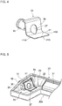
- Fig. 4 is a perspective view of the drain socket 34 in Embodiment 1 of the present invention.
- the drain socket 34 includes an upright plate part 36 fitted onto the inner face 29 of the drain water collecting part 33 and including a drain port 37 for drainage of the drain water to the outside; the drain nozzle part 35 protruding from the drain port 37 and is inserted into the socket mounting hole 27 of the drain pan body 22a; and a flat horizontal plate part 41 extending substantially horizontally from a lower edge of the upright plate part 36 and is placed on the socket mounting face 42 of the drain water collecting part 33.
- the waterproof sheet 71 is attached through the top opening of the drain pan body 22a at the time of molding of the drain pan and covers the inner and bottom faces of the drain pan body 22a. A portion of the waterproof sheet 71 at the drain port 37 of the drain socket 34 is cut out to form an edge portion 71a.
- the waterproof sheet 71 is made of ABS resin with the thickness S of about 0.5 mm.
- the adhesive 72 provides adhesion between the waterproof sheet 71 and the drain pan 22 so that the waterproof sheet 71 does not separate from the drain pan 22.
- the adhesive 72 is made of epoxy resin.
- the waterproof sheet 71 is cut around the drain socket 34 to surround the drain port 37, and the adhesive 72 is applied to an adhesion area 51 to make the waterproof sheet 71 adhere to the drain socket 34.
- the edge portion 71a of the waterproof sheet 71 cut around the drain port 37 of the drain socket 34 is placed on a top face 41b of an edge portion 41a of the horizontal plate part 41 of the drain socket 34, and the adhesive 72 is applied over the edge portion 71a and the top face 41b.
- the top face 41b of the edge portion 41a of the horizontal plate part 41 of the drain socket 34 placed on the socket mounting face 42 of the drain water collecting part 33 is positioned below the bottom face 28 of the drain water collecting part 33.
- the height T from the top face 41b of the edge portion 41a of the horizontal plate part 41 to the bottom face 28 of the drain water collecting part 33 is set larger than the thickness S of the waterproof sheet 71; for example, the height T is set to about 2.5 mm.
- This height T creates a step between the top face 41b of the edge portion 41a of the horizontal plate part 41 and the bottom face 28 of the drain water collecting part 33, and creating this step avoids formation of a mound of the adhesive 72 in adhering the waterproof sheet 71 to the drain socket 34.
- the adhesive 72 is applied over the top face of the edge portion 71a of the waterproof sheet 71 and the top face 41b of the edge portion 41a of the horizontal plate part 41 of the drain socket 34 so as to allow the applied adhesive 72 to slope down toward the top face 41b of the horizontal plate part 41. Applying the adhesive 72 in this way ensures that the drain water is not blocked by the adhesive 72, resulting in a drain pan with improved natural drainage function.
- the heat exchanger 21 is assembled inside the housing 1, and the drain pan 22 is placed below the heat exchanger 21.
- the drain pan 22 includes the drain socket 34 provided with the drain nozzle part 35 projecting to the outside, and attaching a hose 22b to the drain nozzle part 35 completes installation of the air-conditioning indoor unit 100.
- a suction port 25 in a lower part of the housing 1 suctions indoor air to let it pass through the heat exchanger 21, where the indoor air is cooled and air-conditioned.
- the air-conditioned air is blown into the room through a blow duct 26 in an upper part of the housing 1.
- the drain water generated on the surface of the heat exchanger 21 during the air-conditioning drops onto, and is received by, the drain pan 22.
- the top face 41b of the edge portion 41a of the horizontal plate part 41 of the drain socket 34 is positioned below the bottom face 28 of the drain water collecting part 33. This allows for adhesion of the waterproof sheet 71 without having to form a mound of the adhesive 72 that may block the drain water. This ensures drainage of the drain water to the outside.
- the adhesive 72 is applied such that the applied adhesive 72 slopes down toward the top face 41b of the horizontal plate part 41. This facilitates guiding of the drain water on the waterproof sheet 71 toward the horizontal plate part 41 and eventually the drain port 37, ensuring drainage of the drain water to the outside. This can also reduce the amount of adhesive 72 to be applied, enabling low-cost manufacturing.
- the bottom face of the groove 32 of the drain pan body 22a is inclined toward the drain water collecting part 33, and the bottom face and the socket mounting face 42 of the drain water collecting part 33 are slightly inclined toward the drain nozzle part 35. This facilitates natural drainage, to the outside, of the drain water generated in the heat exchanger 21 and other components and received by the drain pan 22, allowing to maintain good drainage of the drain water.
- the top face 41b of the horizontal plate part 41 placed on the socket mounting face 42 lies flush with the bottom face of the drain water collecting part 33, as shown in Fig. 8 .
- the adhesive 72 is used for adhesion between the edge portion 71a of the waterproof sheet 71 and the edge portion 41a of the horizontal plate part 41, a mound of the adhesive 72 is created on the waterproof sheet 71, acting like a dam. This results in the drain water accumulating on the waterproof sheet 71 to the depth of about 2 to 5 mm, which is undesirable.
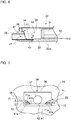
- Fig. 9 is a perspective view of the drain socket in Embodiment 2 of the present invention.
- Fig. 10 is a partial, sectional front view mainly illustrating an adhesion area between the waterproof sheet and the drain socket of the drain pan in Embodiment 2 of the present invention.
- Figs. 8 and 9 the same reference numerals as those in Figs. 4 and 7 refer to the same or corresponding components, and detailed description thereof will be omitted.
- the drain socket 341 used for the air-conditioning indoor unit 100 in Embodiment 2 of the present invention differs from the drain socket in Embodiment 1 in that the drain socket 341 includes an elevated portion 38 raised above the edge portion 41a of the horizontal plate part 41.
- the elevated portion 38 continuous from the upright plate part 36 of the drain socket 341 is formed at the center of the horizontal plate part 41 and at a position higher than the edge portion 41a of the horizontal plate part 41.
- the edge portion 71a of the waterproof sheet 71 is placed on the edge portion 41a of the horizontal plate part 41 around the elevated portion 38.
- the drain water collecting part 33 of the drain pan body 22a is formed with the socket mounting face 42 having an uneven surface conforming to the bottom shape of the horizontal plate part 41 of the drain socket 341.
- the height of the elevated portion 38 is made equal to the height of the waterproof sheet 71 covering the bottom face 28 of the drain water collecting part 33.
- the adhesive 72 is filled onto the edge portion 41a of the horizontal plate part 41 around the elevated portion 38 up to the height flush with a top face of the elevated portion 38.
- the edge portion 71a of the waterproof sheet 71 is placed on the edge portion 41a of the horizontal plate part 41 around the elevated portion 38, the height of the elevated portion 38 is made equal to the height of the waterproof sheet 71, and the adhesive 72 is filled into the recess on the edge portion 41a of the horizontal plate part 41 around the elevated portion 38 up to the height flush with the top face of the elevated portion 38.
- the drain pan according to the present invention is not limited to that used for the floor type air-conditioning indoor unit.
- the shapes described in the above embodiments may be applicable to any other drain pan as long as it includes a drain pan body, a drain socket, and a waterproof sheet.
- the height T of the step may be optionally changed as long as the adhesive 72 does not block the drain water.
Landscapes
- Engineering & Computer Science (AREA)
- Chemical & Material Sciences (AREA)
- Combustion & Propulsion (AREA)
- Mechanical Engineering (AREA)
- General Engineering & Computer Science (AREA)
- Devices For Blowing Cold Air, Devices For Blowing Warm Air, And Means For Preventing Water Condensation In Air Conditioning Units (AREA)
Abstract
Description
- The present invention relates to an air-conditioning indoor unit including a drain pan configured to drain water generated in a cooler and draining it to the outside.
- An existing air-conditioning indoor unit includes a housing, a heat exchanger, a fan, a drain pan, and a control box. One example of such an air-conditioning indoor unit is a floor type indoor unit, or a so-called low-boy type indoor unit.
- A drain pan in the aforementioned indoor unit has a box-like shape with a top opening and includes a drain water collecting part and a recessed water collecting part. The recessed water collecting part includes at its end a drain port, and connecting a hose to the drain port enables drainage of drain water to the outside of the indoor unit through the hose (see Patent Literature 1, for example).
- Patent Literature 1: Japanese Unexamined Patent Application Publication No.
2007-132641 Figs. 1 and2 ) - The drain pan disclosed in Patent Literature 1 is a molded product where a drain water collecting part and a socket mounting face are flush with each other. This drain pan is made of foamed polystyrene beads, which are inexpensive and highly moldable. However, molding the drain pan from polystyrene beads alone may cause water leakage through a gap between beads remaining in the molded product. To prevent the water leakage, a waterproof sheet made of synthetic resin, called skin sheet, is covered from the top opening. The waterproof sheet is adhered at a socket portion with an adhesive so that water does not leak through the gap between beads. This application of the adhesive results in formation of a mound of the adhesive. When this drain pan is used in an air-conditioning indoor unit with a natural drainage system, which is often employed in floor type indoor units, such a mound may cause insufficient drainage of drain water.
- The present invention has been made in view of the above problem and aims at improving drainage of drain water in an air-conditioning indoor unit with a natural drainage system.
- According to an embodiment of the present invention, there is provided an air-conditioning indoor unit including: a cooler; and a drain pan configured to receive drain water generated on a surface of the cooler and drain the drain water to an outside, wherein the drain pan includes: a drain pan body configured to receive the drain water, the drain pan body including: a drain water collecting part configured to gather the drain water; a socket mounting face formed at a bottom face of the drain water collecting part; and a socket mounting hole formed in an inner face of the drain water collecting part and in communication with the outside; a drain socket including: a drain nozzle part inserted into the socket mounting hole; and a horizontal plate part placed on the socket mounting face; a waterproof sheet configured to cover an inner face and a bottom face of the drain pan body; and an adhesive that adheres the waterproof sheet to the drain pan body, and a top face of an edge portion of the horizontal plate part of the drain socket is positioned below the bottom face of the drain water collecting part. Advantageous Effects of Invention
- According to an embodiment of the present invention, the top face of the edge portion of the horizontal plate part of the drain socket placed on the socket mounting face of the drain water collecting part is positioned below the bottom face of the drain water collecting part. This creates a step between the top face of the edge portion of the horizontal plate part and the bottom face of the drain water collecting part. This step can offset the height of the applied adhesive, avoiding formation of a mound of the adhesive that may block the drain water. This results in a drain pan with improved natural drainage function.
-
- [
Fig. 1] Fig. 1 is a perspective view of an exterior of an air-conditioning indoor unit in Embodiment 1 of the present invention. - [
Fig. 2] Fig. 2 is a perspective view of an internal structure of the air-conditioning indoor unit in Embodiment 1 of the present invention. - [
Fig. 3] Fig. 3 is an overall perspective view of a drain pan used in the air-conditioning indoor unit in Embodiment 1 of the present invention. - [
Fig. 4] Fig. 4 is a perspective view of a drain socket in Embodiment 1 of the present invention. - [
Fig. 5] Fig. 5 is a perspective view illustrating how a waterproof sheet is adhered to the drain socket of the drain pan in Embodiment 1 of the present invention. - [
Fig. 6] Fig. 6 is a partial, sectional side view of a longitudinal section of the drain pan in Embodiment 1 of the present invention. - [
Fig. 7] Fig. 7 is a partial, sectional front view mainly illustrating an adhesion area between the waterproof sheet and the drain socket of the drain pan in Embodiment 1 of the present invention. - [
Fig. 8] Fig. 8 is a partial, sectional front view mainly illustrating an adhesion area between a waterproof sheet and a drain socket of a conventional drain pan. - [
Fig. 9] Fig. 9 is a perspective view of the drain socket in Embodiment 2 of the present invention. - [
Fig. 10] Fig. 10 is a partial, sectional front view mainly illustrating an adhesion area between the waterproof sheet and the drain socket of the drain pan in Embodiment 2 of the present invention. - The air-conditioning indoor unit will be explained below with reference to the drawings. Throughout the drawings, including
Fig. 1 , like reference numerals refer to similar or corresponding parts. This holds true for all of the following embodiments in their entirety. Throughout the specification, the forms of elements as given below are by way of example only and not restrictive. When height, size and other factors are described as being high or low or large or small, it is not defined in comparison with a specific absolute value, but relatively defined according to factors such as structures and materials. -
Fig. 1 is a perspective view of an exterior of an air-conditioning indoor unit in Embodiment 1 of the present invention, andFig. 2 is a perspective view of an internal structure of the air-conditioning indoor unit in Embodiment 1 of the present invention. The air-conditioningindoor unit 100 in Embodiment 1 of the present invention is a floor type indoor unit, and its main components include a rectangular, box-like housing 1 and a heat exchanger (an example of the cooler) 21, adrain pan 22, afan 23, and acontrol box 24 installed inside the housing 1. Thedrain pan 22 is placed below theheat exchanger 21 and used to receive drain water such as condensed water generated on a surface of theheat exchanger 21 and dew condensation water generated on surfaces of pipes and other components. - As shown in
Figs. 3 to 7 , thedrain pan 22 includes adrain pan body 22a, adrain socket 34, awaterproof sheet 71, and an adhesive 72. Thedrain pan body 22a includes a heatexchanger receiving plane 31 for receiving theheat exchanger 21, agroove 32 for guiding the drain water, and a drainwater collecting part 33 for gathering the drain water. On aninner face 29 near the drainwater collecting part 33, there is asocket mounting hole 27 communicating with the outside. Thedrain pan body 22a has a top opening and, for example, a substantially rectangular tray shape in plan view to receive the drain water. The drainwater collecting part 33 is formed at one end of thedrain pan body 22a, and a bottom face of thegroove 32 of thedrain pan body 22a is inclined at an inclination angle θ to run down toward the drainwater collecting part 33. This allows the received drain water to gather in the drainwater collecting part 33 naturally. Asocket mounting face 42 depressed downward is formed in an area of the bottom face of the drainwater collecting part 33. The bottom face and thesocket mounting face 42 of the drainwater collecting part 33 are slightly inclined downward toward adrain nozzle part 35. Thus, the drain water gathered in the drainwater collecting part 33 is drained to the outside through adrain socket 34, which will be described below. -
Fig. 4 is a perspective view of thedrain socket 34 in Embodiment 1 of the present invention. Thedrain socket 34 includes anupright plate part 36 fitted onto theinner face 29 of the drainwater collecting part 33 and including adrain port 37 for drainage of the drain water to the outside; thedrain nozzle part 35 protruding from thedrain port 37 and is inserted into thesocket mounting hole 27 of thedrain pan body 22a; and a flathorizontal plate part 41 extending substantially horizontally from a lower edge of theupright plate part 36 and is placed on thesocket mounting face 42 of the drainwater collecting part 33. - The
waterproof sheet 71 is attached through the top opening of thedrain pan body 22a at the time of molding of the drain pan and covers the inner and bottom faces of thedrain pan body 22a. A portion of thewaterproof sheet 71 at thedrain port 37 of thedrain socket 34 is cut out to form anedge portion 71a. For example, thewaterproof sheet 71 is made of ABS resin with the thickness S of about 0.5 mm. Theadhesive 72 provides adhesion between thewaterproof sheet 71 and thedrain pan 22 so that thewaterproof sheet 71 does not separate from thedrain pan 22. For example, the adhesive 72 is made of epoxy resin. - A description will be given on an adhesion structure of the
waterproof sheet 71 around thedrain socket 34. As shown inFig. 5 , thewaterproof sheet 71 is cut around thedrain socket 34 to surround thedrain port 37, and theadhesive 72 is applied to anadhesion area 51 to make thewaterproof sheet 71 adhere to thedrain socket 34. Also, as shown inFig. 7 , theedge portion 71a of thewaterproof sheet 71 cut around thedrain port 37 of thedrain socket 34 is placed on atop face 41b of anedge portion 41a of thehorizontal plate part 41 of thedrain socket 34, and theadhesive 72 is applied over theedge portion 71a and thetop face 41b. - The
top face 41b of theedge portion 41a of thehorizontal plate part 41 of thedrain socket 34 placed on thesocket mounting face 42 of the drainwater collecting part 33 is positioned below thebottom face 28 of the drainwater collecting part 33. The height T from thetop face 41b of theedge portion 41a of thehorizontal plate part 41 to thebottom face 28 of the drainwater collecting part 33 is set larger than the thickness S of thewaterproof sheet 71; for example, the height T is set to about 2.5 mm. This height T creates a step between thetop face 41b of theedge portion 41a of thehorizontal plate part 41 and thebottom face 28 of the drainwater collecting part 33, and creating this step avoids formation of a mound of the adhesive 72 in adhering thewaterproof sheet 71 to thedrain socket 34. More specifically, the adhesive 72 is applied over the top face of theedge portion 71a of thewaterproof sheet 71 and thetop face 41b of theedge portion 41a of thehorizontal plate part 41 of thedrain socket 34 so as to allow the applied adhesive 72 to slope down toward thetop face 41b of thehorizontal plate part 41. Applying the adhesive 72 in this way ensures that the drain water is not blocked by the adhesive 72, resulting in a drain pan with improved natural drainage function. - An operation of the air-conditioning
indoor unit 100 will be described below. In the air-conditioningindoor unit 100, theheat exchanger 21 is assembled inside the housing 1, and thedrain pan 22 is placed below theheat exchanger 21. Thedrain pan 22 includes thedrain socket 34 provided with thedrain nozzle part 35 projecting to the outside, and attaching ahose 22b to thedrain nozzle part 35 completes installation of the air-conditioningindoor unit 100. Then, upon driving of thefan 23, asuction port 25 in a lower part of the housing 1 suctions indoor air to let it pass through theheat exchanger 21, where the indoor air is cooled and air-conditioned. The air-conditioned air is blown into the room through ablow duct 26 in an upper part of the housing 1. The drain water generated on the surface of theheat exchanger 21 during the air-conditioning drops onto, and is received by, thedrain pan 22. - As described above, in the
drain pan 22 of the air-conditioningindoor unit 100 in Embodiment 1, thetop face 41b of theedge portion 41a of thehorizontal plate part 41 of thedrain socket 34 is positioned below thebottom face 28 of the drainwater collecting part 33. This allows for adhesion of thewaterproof sheet 71 without having to form a mound of the adhesive 72 that may block the drain water. This ensures drainage of the drain water to the outside. - Additionally, the adhesive 72 is applied such that the applied adhesive 72 slopes down toward the
top face 41b of thehorizontal plate part 41. This facilitates guiding of the drain water on thewaterproof sheet 71 toward thehorizontal plate part 41 and eventually thedrain port 37, ensuring drainage of the drain water to the outside. This can also reduce the amount of adhesive 72 to be applied, enabling low-cost manufacturing. - The bottom face of the
groove 32 of thedrain pan body 22a is inclined toward the drainwater collecting part 33, and the bottom face and thesocket mounting face 42 of the drainwater collecting part 33 are slightly inclined toward thedrain nozzle part 35. This facilitates natural drainage, to the outside, of the drain water generated in theheat exchanger 21 and other components and received by thedrain pan 22, allowing to maintain good drainage of the drain water. - For comparison, in a conventional drain pan, the
top face 41b of thehorizontal plate part 41 placed on thesocket mounting face 42 lies flush with the bottom face of the drainwater collecting part 33, as shown inFig. 8 . In that case, when the adhesive 72 is used for adhesion between theedge portion 71a of thewaterproof sheet 71 and theedge portion 41a of thehorizontal plate part 41, a mound of the adhesive 72 is created on thewaterproof sheet 71, acting like a dam. This results in the drain water accumulating on thewaterproof sheet 71 to the depth of about 2 to 5 mm, which is undesirable. - A description will now be given on the air-conditioning indoor unit in Embodiment 2 of the present invention.
Fig. 9 is a perspective view of the drain socket in Embodiment 2 of the present invention.Fig. 10 is a partial, sectional front view mainly illustrating an adhesion area between the waterproof sheet and the drain socket of the drain pan in Embodiment 2 of the present invention. InFigs. 8 and 9 , the same reference numerals as those inFigs. 4 and7 refer to the same or corresponding components, and detailed description thereof will be omitted. - The
drain socket 341 used for the air-conditioningindoor unit 100 in Embodiment 2 of the present invention differs from the drain socket in Embodiment 1 in that thedrain socket 341 includes anelevated portion 38 raised above theedge portion 41a of thehorizontal plate part 41. - More specifically, the
elevated portion 38 continuous from theupright plate part 36 of thedrain socket 341 is formed at the center of thehorizontal plate part 41 and at a position higher than theedge portion 41a of thehorizontal plate part 41. Theedge portion 71a of thewaterproof sheet 71 is placed on theedge portion 41a of thehorizontal plate part 41 around theelevated portion 38. The drainwater collecting part 33 of thedrain pan body 22a is formed with thesocket mounting face 42 having an uneven surface conforming to the bottom shape of thehorizontal plate part 41 of thedrain socket 341. The height of theelevated portion 38 is made equal to the height of thewaterproof sheet 71 covering thebottom face 28 of the drainwater collecting part 33. The adhesive 72 is filled onto theedge portion 41a of thehorizontal plate part 41 around theelevated portion 38 up to the height flush with a top face of theelevated portion 38. - As described above, in Embodiment 2, the
edge portion 71a of thewaterproof sheet 71 is placed on theedge portion 41a of thehorizontal plate part 41 around theelevated portion 38, the height of theelevated portion 38 is made equal to the height of thewaterproof sheet 71, and the adhesive 72 is filled into the recess on theedge portion 41a of thehorizontal plate part 41 around theelevated portion 38 up to the height flush with the top face of theelevated portion 38. This avoids formation of a mound of the adhesive 72, preventing the adhesive 72 from blocking the drain water. This also allows for easy control of the amount of adhesive 72 to be applied. - The drain pan according to the present invention is not limited to that used for the floor type air-conditioning indoor unit. The shapes described in the above embodiments may be applicable to any other drain pan as long as it includes a drain pan body, a drain socket, and a waterproof sheet. Also, the height T of the step may be optionally changed as long as the adhesive 72 does not block the drain water.
- 1
housing 21 heat exchanger (cooler) 22drain pan 22adrain pan 23body 22b hosefan 24control box 25suction port 26blow duct 27socket mounting hole 28bottom face 29inner face 31 heatexchanger receiving plane 32groove 33 drainwater collecting part drain socket 35drain nozzle part 36upright plate part 37drain port 38elevated portion 41horizontal plate part 41a edge portion 41btop face 42socket mounting face 51adhesion area 71waterproof sheet 71a edge portion 72 adhesive 100 air-conditioning indoor unit S thickness T height θ inclination angle
Claims (5)
- An air-conditioning indoor unit comprising:a cooler; anda drain pan configured to receive drain water generated on a surface of the cooler and drain the drain water to an outside, whereinthe drain pan includes:a drain pan body configured to receive the drain water, the drain pan body including: a drain water collecting part configured to gather the drain water; a socket mounting face formed at a bottom face of the drain water collecting part; and a socket mounting hole formed in an inner face of the drain water collecting part and in communication with the outside;a drain socket including: a drain nozzle part inserted into the socket mounting hole; and a horizontal plate part placed on the socket mounting face;a waterproof sheet configured to cover an inner face and a bottom face of the drain pan body; andan adhesive that adheres the waterproof sheet to the drain pan body, anda top face of an edge portion of the horizontal plate part of the drain socket is positioned below the bottom face of the drain water collecting part.
- The air-conditioning indoor unit of claim 1, wherein the adhesive is applied such that applied adhesive slopes down toward the top face of the horizontal plate part.
- The air-conditioning indoor unit of claim 1, wherein
the horizontal plate part includes an elevated portion raised above the edge portion of the horizontal plate part,
the elevated portion has height equal to height of the waterproof sheet covering the bottom face of the drain water collecting part, and
the adhesive is filled onto the edge portion of the horizontal plate part around the elevated portion. - The air-conditioning indoor unit of any one of claims 1 to 3, wherein the bottom face of the drain pan body is inclined downward toward the drain water collecting part.
- The air-conditioning indoor unit of any one of claims 1 to 4, wherein the socket mounting face is inclined downward toward the drain nozzle part.
Applications Claiming Priority (1)
| Application Number | Priority Date | Filing Date | Title |
|---|---|---|---|
| PCT/JP2017/023667 WO2019003327A1 (en) | 2017-06-28 | 2017-06-28 | INDOOR AIR CONDITIONING UNIT |
Publications (3)
| Publication Number | Publication Date |
|---|---|
| EP3647675A1 true EP3647675A1 (en) | 2020-05-06 |
| EP3647675A4 EP3647675A4 (en) | 2020-09-16 |
| EP3647675B1 EP3647675B1 (en) | 2023-04-05 |
Family
ID=64740472
Family Applications (1)
| Application Number | Title | Priority Date | Filing Date |
|---|---|---|---|
| EP17915223.6A Active EP3647675B1 (en) | 2017-06-28 | 2017-06-28 | Air conditioning indoor unit |
Country Status (3)
| Country | Link |
|---|---|
| EP (1) | EP3647675B1 (en) |
| JP (1) | JP6793832B2 (en) |
| WO (1) | WO2019003327A1 (en) |
Family Cites Families (5)
| Publication number | Priority date | Publication date | Assignee | Title |
|---|---|---|---|---|
| JPS6333058Y2 (en) * | 1984-12-15 | 1988-09-05 | ||
| JPH0478416U (en) * | 1990-11-22 | 1992-07-08 | ||
| JP3854402B2 (en) * | 1998-01-29 | 2006-12-06 | 三菱重工業株式会社 | Drain discharge mechanism of air conditioner |
| JP2007132641A (en) | 2005-11-14 | 2007-05-31 | Sanki Eng Co Ltd | Drain pan |
| KR100716251B1 (en) * | 2005-12-26 | 2007-05-08 | 삼성전자주식회사 | Air conditioner |
-
2017
- 2017-06-28 EP EP17915223.6A patent/EP3647675B1/en active Active
- 2017-06-28 WO PCT/JP2017/023667 patent/WO2019003327A1/en not_active Ceased
- 2017-06-28 JP JP2019526450A patent/JP6793832B2/en active Active
Also Published As
| Publication number | Publication date |
|---|---|
| JP6793832B2 (en) | 2020-12-02 |
| EP3647675A4 (en) | 2020-09-16 |
| JPWO2019003327A1 (en) | 2020-01-16 |
| WO2019003327A1 (en) | 2019-01-03 |
| EP3647675B1 (en) | 2023-04-05 |
Similar Documents
| Publication | Publication Date | Title |
|---|---|---|
| US10051756B2 (en) | Surround for electrical boxes | |
| EP2416638A2 (en) | Electronic Device | |
| US20090023377A1 (en) | Vent system insert apparatus and method for installation | |
| WO2012130100A1 (en) | Ventilating fan | |
| US6835129B1 (en) | Heating, ventilation, and air-conditioning duct boot seal | |
| EP3647675B1 (en) | Air conditioning indoor unit | |
| CN210643955U (en) | Dish washing machine door body and dish washing machine applying door body | |
| US20150260427A1 (en) | Connector frame for duct boot | |
| CN210107578U (en) | An air conditioner outdoor unit waterproof and insect proof structure and air conditioner | |
| CN204787096U (en) | A air conditioner that is used for ornamental strip structure of interior machine of air conditioning and has it | |
| CN209068728U (en) | Drip tray mounting structure and air-cooled ducted air conditioner | |
| CN213687022U (en) | Air conditioner indoor unit and air conditioner | |
| JPS6122189Y2 (en) | ||
| JP5152090B2 (en) | Exterior wall structure | |
| CN223580335U (en) | Refrigeration equipment | |
| CN209003459U (en) | A kind of Intelligent water cup robot | |
| CN208382340U (en) | Air conditioner indoor unit and air conditioner | |
| CN223375982U (en) | Fresh air module and air conditioner | |
| CN206959296U (en) | A kind of understructure of air-conditioning | |
| CN222027040U (en) | Mask unit and air dispatching equipment | |
| JPS6223201Y2 (en) | ||
| CN220728483U (en) | Air distribution box and fresh air system | |
| CN212672117U (en) | Integrated cooling air duct structure of vehicle blower mounting disc | |
| CN213821156U (en) | Shower tray | |
| EP2808615B1 (en) | Indoor unit for air-conditioning apparatus |
Legal Events
| Date | Code | Title | Description |
|---|---|---|---|
| STAA | Information on the status of an ep patent application or granted ep patent |
Free format text: STATUS: THE INTERNATIONAL PUBLICATION HAS BEEN MADE |
|
| PUAI | Public reference made under article 153(3) epc to a published international application that has entered the european phase |
Free format text: ORIGINAL CODE: 0009012 |
|
| STAA | Information on the status of an ep patent application or granted ep patent |
Free format text: STATUS: REQUEST FOR EXAMINATION WAS MADE |
|
| 17P | Request for examination filed |
Effective date: 20191017 |
|
| AK | Designated contracting states |
Kind code of ref document: A1 Designated state(s): AL AT BE BG CH CY CZ DE DK EE ES FI FR GB GR HR HU IE IS IT LI LT LU LV MC MK MT NL NO PL PT RO RS SE SI SK SM TR |
|
| AX | Request for extension of the european patent |
Extension state: BA ME |
|
| A4 | Supplementary search report drawn up and despatched |
Effective date: 20200814 |
|
| RIC1 | Information provided on ipc code assigned before grant |
Ipc: F24F 1/0007 20190101ALI20200810BHEP Ipc: F24F 13/22 20060101AFI20200810BHEP |
|
| DAV | Request for validation of the european patent (deleted) | ||
| DAX | Request for extension of the european patent (deleted) | ||
| GRAP | Despatch of communication of intention to grant a patent |
Free format text: ORIGINAL CODE: EPIDOSNIGR1 |
|
| STAA | Information on the status of an ep patent application or granted ep patent |
Free format text: STATUS: GRANT OF PATENT IS INTENDED |
|
| INTG | Intention to grant announced |
Effective date: 20221213 |
|
| GRAS | Grant fee paid |
Free format text: ORIGINAL CODE: EPIDOSNIGR3 |
|
| GRAA | (expected) grant |
Free format text: ORIGINAL CODE: 0009210 |
|
| STAA | Information on the status of an ep patent application or granted ep patent |
Free format text: STATUS: THE PATENT HAS BEEN GRANTED |
|
| AK | Designated contracting states |
Kind code of ref document: B1 Designated state(s): AL AT BE BG CH CY CZ DE DK EE ES FI FR GB GR HR HU IE IS IT LI LT LU LV MC MK MT NL NO PL PT RO RS SE SI SK SM TR |
|
| REG | Reference to a national code |
Ref country code: GB Ref legal event code: FG4D |
|
| REG | Reference to a national code |
Ref country code: DE Ref legal event code: R096 Ref document number: 602017067584 Country of ref document: DE |
|
| REG | Reference to a national code |
Ref country code: CH Ref legal event code: EP |
|
| REG | Reference to a national code |
Ref country code: AT Ref legal event code: REF Ref document number: 1558505 Country of ref document: AT Kind code of ref document: T Effective date: 20230415 |
|
| REG | Reference to a national code |
Ref country code: IE Ref legal event code: FG4D |
|
| REG | Reference to a national code |
Ref country code: LT Ref legal event code: MG9D |
|
| REG | Reference to a national code |
Ref country code: NL Ref legal event code: MP Effective date: 20230405 |
|
| P01 | Opt-out of the competence of the unified patent court (upc) registered |
Effective date: 20230711 |
|
| REG | Reference to a national code |
Ref country code: AT Ref legal event code: MK05 Ref document number: 1558505 Country of ref document: AT Kind code of ref document: T Effective date: 20230405 |
|
| PG25 | Lapsed in a contracting state [announced via postgrant information from national office to epo] |
Ref country code: NL Free format text: LAPSE BECAUSE OF FAILURE TO SUBMIT A TRANSLATION OF THE DESCRIPTION OR TO PAY THE FEE WITHIN THE PRESCRIBED TIME-LIMIT Effective date: 20230405 |
|
| PG25 | Lapsed in a contracting state [announced via postgrant information from national office to epo] |
Ref country code: SE Free format text: LAPSE BECAUSE OF FAILURE TO SUBMIT A TRANSLATION OF THE DESCRIPTION OR TO PAY THE FEE WITHIN THE PRESCRIBED TIME-LIMIT Effective date: 20230405 Ref country code: PT Free format text: LAPSE BECAUSE OF FAILURE TO SUBMIT A TRANSLATION OF THE DESCRIPTION OR TO PAY THE FEE WITHIN THE PRESCRIBED TIME-LIMIT Effective date: 20230807 Ref country code: NO Free format text: LAPSE BECAUSE OF FAILURE TO SUBMIT A TRANSLATION OF THE DESCRIPTION OR TO PAY THE FEE WITHIN THE PRESCRIBED TIME-LIMIT Effective date: 20230705 Ref country code: ES Free format text: LAPSE BECAUSE OF FAILURE TO SUBMIT A TRANSLATION OF THE DESCRIPTION OR TO PAY THE FEE WITHIN THE PRESCRIBED TIME-LIMIT Effective date: 20230405 Ref country code: AT Free format text: LAPSE BECAUSE OF FAILURE TO SUBMIT A TRANSLATION OF THE DESCRIPTION OR TO PAY THE FEE WITHIN THE PRESCRIBED TIME-LIMIT Effective date: 20230405 |
|
| PG25 | Lapsed in a contracting state [announced via postgrant information from national office to epo] |
Ref country code: RS Free format text: LAPSE BECAUSE OF FAILURE TO SUBMIT A TRANSLATION OF THE DESCRIPTION OR TO PAY THE FEE WITHIN THE PRESCRIBED TIME-LIMIT Effective date: 20230405 Ref country code: PL Free format text: LAPSE BECAUSE OF FAILURE TO SUBMIT A TRANSLATION OF THE DESCRIPTION OR TO PAY THE FEE WITHIN THE PRESCRIBED TIME-LIMIT Effective date: 20230405 Ref country code: LV Free format text: LAPSE BECAUSE OF FAILURE TO SUBMIT A TRANSLATION OF THE DESCRIPTION OR TO PAY THE FEE WITHIN THE PRESCRIBED TIME-LIMIT Effective date: 20230405 Ref country code: LT Free format text: LAPSE BECAUSE OF FAILURE TO SUBMIT A TRANSLATION OF THE DESCRIPTION OR TO PAY THE FEE WITHIN THE PRESCRIBED TIME-LIMIT Effective date: 20230405 Ref country code: IS Free format text: LAPSE BECAUSE OF FAILURE TO SUBMIT A TRANSLATION OF THE DESCRIPTION OR TO PAY THE FEE WITHIN THE PRESCRIBED TIME-LIMIT Effective date: 20230805 Ref country code: HR Free format text: LAPSE BECAUSE OF FAILURE TO SUBMIT A TRANSLATION OF THE DESCRIPTION OR TO PAY THE FEE WITHIN THE PRESCRIBED TIME-LIMIT Effective date: 20230405 Ref country code: GR Free format text: LAPSE BECAUSE OF FAILURE TO SUBMIT A TRANSLATION OF THE DESCRIPTION OR TO PAY THE FEE WITHIN THE PRESCRIBED TIME-LIMIT Effective date: 20230706 Ref country code: AL Free format text: LAPSE BECAUSE OF FAILURE TO SUBMIT A TRANSLATION OF THE DESCRIPTION OR TO PAY THE FEE WITHIN THE PRESCRIBED TIME-LIMIT Effective date: 20230405 |
|
| PG25 | Lapsed in a contracting state [announced via postgrant information from national office to epo] |
Ref country code: FI Free format text: LAPSE BECAUSE OF FAILURE TO SUBMIT A TRANSLATION OF THE DESCRIPTION OR TO PAY THE FEE WITHIN THE PRESCRIBED TIME-LIMIT Effective date: 20230405 |
|
| REG | Reference to a national code |
Ref country code: DE Ref legal event code: R119 Ref document number: 602017067584 Country of ref document: DE |
|
| PG25 | Lapsed in a contracting state [announced via postgrant information from national office to epo] |
Ref country code: SK Free format text: LAPSE BECAUSE OF FAILURE TO SUBMIT A TRANSLATION OF THE DESCRIPTION OR TO PAY THE FEE WITHIN THE PRESCRIBED TIME-LIMIT Effective date: 20230405 |
|
| PG25 | Lapsed in a contracting state [announced via postgrant information from national office to epo] |
Ref country code: MC Free format text: LAPSE BECAUSE OF FAILURE TO SUBMIT A TRANSLATION OF THE DESCRIPTION OR TO PAY THE FEE WITHIN THE PRESCRIBED TIME-LIMIT Effective date: 20230405 |
|
| PG25 | Lapsed in a contracting state [announced via postgrant information from national office to epo] |
Ref country code: SM Free format text: LAPSE BECAUSE OF FAILURE TO SUBMIT A TRANSLATION OF THE DESCRIPTION OR TO PAY THE FEE WITHIN THE PRESCRIBED TIME-LIMIT Effective date: 20230405 Ref country code: SK Free format text: LAPSE BECAUSE OF FAILURE TO SUBMIT A TRANSLATION OF THE DESCRIPTION OR TO PAY THE FEE WITHIN THE PRESCRIBED TIME-LIMIT Effective date: 20230405 Ref country code: RO Free format text: LAPSE BECAUSE OF FAILURE TO SUBMIT A TRANSLATION OF THE DESCRIPTION OR TO PAY THE FEE WITHIN THE PRESCRIBED TIME-LIMIT Effective date: 20230405 Ref country code: MC Free format text: LAPSE BECAUSE OF FAILURE TO SUBMIT A TRANSLATION OF THE DESCRIPTION OR TO PAY THE FEE WITHIN THE PRESCRIBED TIME-LIMIT Effective date: 20230405 Ref country code: EE Free format text: LAPSE BECAUSE OF FAILURE TO SUBMIT A TRANSLATION OF THE DESCRIPTION OR TO PAY THE FEE WITHIN THE PRESCRIBED TIME-LIMIT Effective date: 20230405 Ref country code: DK Free format text: LAPSE BECAUSE OF FAILURE TO SUBMIT A TRANSLATION OF THE DESCRIPTION OR TO PAY THE FEE WITHIN THE PRESCRIBED TIME-LIMIT Effective date: 20230405 Ref country code: CZ Free format text: LAPSE BECAUSE OF FAILURE TO SUBMIT A TRANSLATION OF THE DESCRIPTION OR TO PAY THE FEE WITHIN THE PRESCRIBED TIME-LIMIT Effective date: 20230405 |
|
| REG | Reference to a national code |
Ref country code: CH Ref legal event code: PL |
|
| PLBE | No opposition filed within time limit |
Free format text: ORIGINAL CODE: 0009261 |
|
| STAA | Information on the status of an ep patent application or granted ep patent |
Free format text: STATUS: NO OPPOSITION FILED WITHIN TIME LIMIT |
|
| REG | Reference to a national code |
Ref country code: BE Ref legal event code: MM Effective date: 20230630 |
|
| PG25 | Lapsed in a contracting state [announced via postgrant information from national office to epo] |
Ref country code: LU Free format text: LAPSE BECAUSE OF NON-PAYMENT OF DUE FEES Effective date: 20230628 |
|
| 26N | No opposition filed |
Effective date: 20240108 |
|
| REG | Reference to a national code |
Ref country code: IE Ref legal event code: MM4A |
|
| PG25 | Lapsed in a contracting state [announced via postgrant information from national office to epo] |
Ref country code: LU Free format text: LAPSE BECAUSE OF NON-PAYMENT OF DUE FEES Effective date: 20230628 |
|
| PG25 | Lapsed in a contracting state [announced via postgrant information from national office to epo] |
Ref country code: IE Free format text: LAPSE BECAUSE OF NON-PAYMENT OF DUE FEES Effective date: 20230628 |
|
| PG25 | Lapsed in a contracting state [announced via postgrant information from national office to epo] |
Ref country code: IE Free format text: LAPSE BECAUSE OF NON-PAYMENT OF DUE FEES Effective date: 20230628 Ref country code: DE Free format text: LAPSE BECAUSE OF NON-PAYMENT OF DUE FEES Effective date: 20240103 Ref country code: CH Free format text: LAPSE BECAUSE OF NON-PAYMENT OF DUE FEES Effective date: 20230630 |
|
| PG25 | Lapsed in a contracting state [announced via postgrant information from national office to epo] |
Ref country code: SI Free format text: LAPSE BECAUSE OF FAILURE TO SUBMIT A TRANSLATION OF THE DESCRIPTION OR TO PAY THE FEE WITHIN THE PRESCRIBED TIME-LIMIT Effective date: 20230405 |
|
| PG25 | Lapsed in a contracting state [announced via postgrant information from national office to epo] |
Ref country code: SI Free format text: LAPSE BECAUSE OF FAILURE TO SUBMIT A TRANSLATION OF THE DESCRIPTION OR TO PAY THE FEE WITHIN THE PRESCRIBED TIME-LIMIT Effective date: 20230405 Ref country code: FR Free format text: LAPSE BECAUSE OF NON-PAYMENT OF DUE FEES Effective date: 20230630 Ref country code: BE Free format text: LAPSE BECAUSE OF NON-PAYMENT OF DUE FEES Effective date: 20230630 |
|
| PGFP | Annual fee paid to national office [announced via postgrant information from national office to epo] |
Ref country code: GB Payment date: 20240509 Year of fee payment: 8 |
|
| PGFP | Annual fee paid to national office [announced via postgrant information from national office to epo] |
Ref country code: IT Payment date: 20240513 Year of fee payment: 8 |
|
| PG25 | Lapsed in a contracting state [announced via postgrant information from national office to epo] |
Ref country code: BG Free format text: LAPSE BECAUSE OF FAILURE TO SUBMIT A TRANSLATION OF THE DESCRIPTION OR TO PAY THE FEE WITHIN THE PRESCRIBED TIME-LIMIT Effective date: 20230405 |
|
| PG25 | Lapsed in a contracting state [announced via postgrant information from national office to epo] |
Ref country code: BG Free format text: LAPSE BECAUSE OF FAILURE TO SUBMIT A TRANSLATION OF THE DESCRIPTION OR TO PAY THE FEE WITHIN THE PRESCRIBED TIME-LIMIT Effective date: 20230405 |
|
| PG25 | Lapsed in a contracting state [announced via postgrant information from national office to epo] |
Ref country code: CY Free format text: LAPSE BECAUSE OF FAILURE TO SUBMIT A TRANSLATION OF THE DESCRIPTION OR TO PAY THE FEE WITHIN THE PRESCRIBED TIME-LIMIT; INVALID AB INITIO Effective date: 20170628 |
|
| PG25 | Lapsed in a contracting state [announced via postgrant information from national office to epo] |
Ref country code: HU Free format text: LAPSE BECAUSE OF FAILURE TO SUBMIT A TRANSLATION OF THE DESCRIPTION OR TO PAY THE FEE WITHIN THE PRESCRIBED TIME-LIMIT; INVALID AB INITIO Effective date: 20170628 |
|
| PG25 | Lapsed in a contracting state [announced via postgrant information from national office to epo] |
Ref country code: TR Free format text: LAPSE BECAUSE OF FAILURE TO SUBMIT A TRANSLATION OF THE DESCRIPTION OR TO PAY THE FEE WITHIN THE PRESCRIBED TIME-LIMIT Effective date: 20230405 |
|
| GBPC | Gb: european patent ceased through non-payment of renewal fee |
Effective date: 20250628 |
|
| PG25 | Lapsed in a contracting state [announced via postgrant information from national office to epo] |
Ref country code: GB Free format text: LAPSE BECAUSE OF NON-PAYMENT OF DUE FEES Effective date: 20250628 |
|
| PG25 | Lapsed in a contracting state [announced via postgrant information from national office to epo] |
Ref country code: IT Free format text: LAPSE BECAUSE OF NON-PAYMENT OF DUE FEES Effective date: 20250628 |