EP3647662A1 - Push-in push-out control knob for a domestic appliance - Google Patents
Push-in push-out control knob for a domestic appliance Download PDFInfo
- Publication number
- EP3647662A1 EP3647662A1 EP18203283.9A EP18203283A EP3647662A1 EP 3647662 A1 EP3647662 A1 EP 3647662A1 EP 18203283 A EP18203283 A EP 18203283A EP 3647662 A1 EP3647662 A1 EP 3647662A1
- Authority
- EP
- European Patent Office
- Prior art keywords
- push
- control knob
- out control
- support element
- ring
- Prior art date
- Legal status (The legal status is an assumption and is not a legal conclusion. Google has not performed a legal analysis and makes no representation as to the accuracy of the status listed.)
- Withdrawn
Links
- 238000010411 cooking Methods 0.000 claims abstract description 6
- 229920003023 plastic Polymers 0.000 claims description 9
- 239000004033 plastic Substances 0.000 claims description 9
- 239000002184 metal Substances 0.000 claims description 6
- 239000011521 glass Substances 0.000 description 2
- 230000004048 modification Effects 0.000 description 2
- 238000012986 modification Methods 0.000 description 2
Images



Classifications
-
- F—MECHANICAL ENGINEERING; LIGHTING; HEATING; WEAPONS; BLASTING
- F24—HEATING; RANGES; VENTILATING
- F24C—DOMESTIC STOVES OR RANGES ; DETAILS OF DOMESTIC STOVES OR RANGES, OF GENERAL APPLICATION
- F24C7/00—Stoves or ranges heated by electric energy
- F24C7/08—Arrangement or mounting of control or safety devices
-
- G—PHYSICS
- G05—CONTROLLING; REGULATING
- G05G—CONTROL DEVICES OR SYSTEMS INSOFAR AS CHARACTERISED BY MECHANICAL FEATURES ONLY
- G05G1/00—Controlling members, e.g. knobs or handles; Assemblies or arrangements thereof; Indicating position of controlling members
- G05G1/08—Controlling members for hand actuation by rotary movement, e.g. hand wheels
- G05G1/087—Controlling members for hand actuation by rotary movement, e.g. hand wheels retractable; Flush control knobs
Definitions
- the present invention relates to a push-in-push-out control knob for a domestic appliance.
- the present invention relates to a push-in-push-out control knob for a cooking appliance.
- the present invention relates to a domestic appliance.
- a push-in-push-out control knob is arranged within a control panel of a domestic appliance.
- the push-in-push-out control knob is counter-sunk in the control panel, when said push-in-push-out control knob is not in use.
- the push-in-push-out control knob protrudes out of the control panel, when said push-in-push-out control knob is in use.
- the push-in-push-out control knob is rotatable in the protruding state.
- FIG 17 illustrates a schematic exploded perspective view of the push-in-push-out control knob 10 according to the prior art.
- the push-in-push-out control knob 10 comprises a proper control knob 32, a guiding ring 34, a housing 22 with a flange and a switch mechanism 26.
- the push-in-push-out control knob 10 is assembled at the control panel 30 of the domestic appliance from the front side. However, the push-in-push-out control knob 10 wobbles, when it is gripped by the user.
- FIG 18 illustrates a schematic exploded perspective view of a further push-in-push-out control knob 10 according to the prior art.
- the push-in-push-out control knob 10 comprises the proper control knob 32, the guiding ring 34, the housing 22 with flange, a rear knob part 36 and the switch mechanism 26.
- the push-in-push-out control knob 10 is assembled at the control panel 30 of the domestic appliance from the rear side.
- the assembling of the push-in-push-out control knob 10 at the control panel 30 is complex, since other control knobs are assembled from the front side of the control panel 30.
- the object is achieved by the push-in-push-out control knob for a domestic appliance according to claim 1.
- a push-in-push-out control knob for a domestic appliance in particular for a cooking appliance, is provided, wherein:
- the core of the present invention is the ring in the front opening of the housing, which is engaged from behind by the support element.
- the ring reduces wobbling of the push-in-push-out control knob.
- the push-in-push-out control knob is assembled by low complexity, since the outer component is arranged at the front side of the control panel, while the inner component is arranged at the rear side of the control panel.
- the support element includes at least two snap-in hooks for engaging behind the ring, wherein said snap-in hooks form an enlarging of the support element.
- the support element may include at least two wings extending along a push direction of the push-in-push-out control knob, wherein at least one snap-in hook is formed at a rear distal end of said wing.
- a plurality of snap-in hooks extends around the circumference of the support element and forms the enlarging of said support element.
- the outer component may include a spring mechanism providing a force for pressing the support element, particularly the snap-in hooks, against the ring.
- the inner component may include a switch mechanism, wherein preferably said switch mechanism is connected or connectable to the spring mechanism of the outer component.
- the switch mechanism is a switch, a thermostat, an encoder or any input command device.
- the outer component includes a cap element enclosing partially the support element, so that the cap element and the support element form a control knob.
- the cap element is made of metal or plastics.
- the support element may form a control knob.
- the push-in-push-out control knob may be rotatable around a rotation axis perpendicular to the plane of the control panel, wherein the push-in-push-out control knob is moveable along said rotation axis between a protruding state and a countersunk state.
- the wings form a cylindrical surface of the support element and extend parallel to the rotation axis of the push-in-push-out control knob.
- the push-in-push-out control knob is attachable at a circular cut-out in the control panel of the domestic appliance, wherein the diameter of the ring is marginally bigger than the diameter of said circular cut-out.
- the present invention relates to a domestic appliance, in particular a cooking appliance, wherein the domestic appliance comprises at least one push-in-push-out control knob mentioned above.
- the domestic appliance may comprise at least one control panel including at least one cut-out, wherein the push-in-push-out control knob is attached or attachable at said cut-out in the control panel of the domestic appliance.
- the diameter of the cut-out in the control panel may be marginally smaller than the diameter of the ring of the push-in-push-out control knob, wherein preferably the cut-out in the control panel is circular.
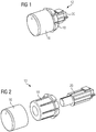
- FIG 1 illustrates a schematic perspective view of an outer component 12 of a push-in-push-out control knob 10 according to a preferred embodiment of the present invention.
- the outer component 12 of the push-in-push-out control knob 10 comprises a cap element 16, a support element 18 and a spring mechanism 20.
- the cap element 16 is substantially cylindrical and includes a closed face side and an open face side.
- the support element 18 is also substantially cylindrical and includes a plurality of elastic wings. Said wings extend on the curved surface and along the symmetry axis of the support element 18. Each wing includes a snap-in hook at the distal end of said wing. The snap-in hooks form an enlarging of the support element 18. Said enlarging extends in circumferential direction of the support element 18. Except the enlarging the support element 18 is completely enclosed by the cap element 16.
- the spring mechanism 20 is partially received by the cap element 16 and the support element 18.
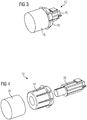
- FIG 2 illustrates a schematic exploded perspective view of the outer component 12 of the push-in-push-out control knob 10 according to the preferred embodiment of the present invention.
- the structures of the support element 18 and spring mechanism 20 are clarified in FIG 2 .
- the spring mechanism 20 is partially received by the cap element 16.
- the support element 18 is pressed between said spring mechanism 20 and cap element 16.
- the cap element 16 is made at least partially of metal, while the support element 18 is made of plastics.
- the frontal part of the cap element 16 as shown in the left region of figure 2 is formed as a frontal cap while the remaining part of the cap element 16 can be made of plastics and can be adapted to receive said frontal cap, wherein the frontal cap can be made of plastics or preferably of metal.
- the support element 18 may be provided without wings. Still in alternative, the wings can be embodied directly on the cap element and the support element 18 can be left away.
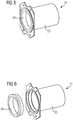
- FIG 3 illustrates a schematic perspective view of another example of the outer component 12 of the push-in-push-out control knob 10 according to the preferred embodiment of the present invention.
- the outer component 12 in FIG 3 is similar as the outer component 12 of FIG 1 and 2 .
- the cap element 16 in FIG 3 is made of plastics.
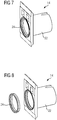
- FIG 4 illustrates a schematic exploded perspective view of the other example of the outer component 12 of the push-in-push-out control knob 10 according to the preferred embodiment of the present invention.
- the outer component 12 in FIG 4 includes the cap element 16 made of plastics.
- FIG 5 illustrates a schematic perspective view of an inner component 14 of the push-in-push-out control knob 10 according to the preferred embodiment of the present invention.
- the inner component 14 comprises a housing 22 and a ring 24. Further, the inner component 14 comprises a switch mechanism 26, which is not shown in FIG 5 .
- the housing 22 is a pipe section with a flange.
- the ring 24 is enclosed by said flange.
- the flange is attachable at a rear side of a control panel 30.
- the flange is attachable at a rear side of a control panel 30 made of metal.
- the inner component 14 may be formed as a single-piece part.
- FIG 6 illustrates a schematic exploded perspective view of the inner component 14 of the push-in-push-out control knob 10 according to the preferred embodiment of the present invention.
- the structure and size of the ring 24 is clarified in FIG 6 .
- FIG 7 illustrates a schematic perspective view of another example of the inner component 14 of the push-in-push-out control knob 10 according to the preferred embodiment of the present invention.
- the inner component 14 comprises the housing 22 and the ring 24. Moreover, the inner component 14 comprises the switch mechanism 26, which is not shown in FIG 7 .
- the housing 22 is substantially formed as pipe section with flange.
- the ring 24 is enclosed by said flange.
- the flange is attachable at a rear side of a control panel 30 made of glass.
- the inner component 14 may be formed as a single-piece part.
- FIG 8 illustrates a schematic exploded perspective view of the other example of the inner component 14 of the push-in-push-out control knob 10 according to the preferred embodiment of the present invention.
- the flange of the housing is attachable at the rear side of the control panel 30 made of glass.
- FIG 9 illustrates a schematic sectional side view of the push-in-push-out control knob 10 assembled in the control panel 30 according to the preferred embodiment of the present invention.
- the push-in-push-out control knob 10 is assembled in a circular cut-out of the control panel 30.
- the first component 12 of the push-in-push-out control knob 10 is assembled from the front side of the control panel 30, while the second component 14 of the push-in-push-out control knob 10 is assembled from the rear side of said control panel 30.
- the flange of the housing 22 is aligned at the rear side of said control panel 30.
- the switch mechanism 26 is arranged inside said housing 22.
- the spring mechanism 20 is arranged substantially inside the cap element 16 and the support element 18.
- the ring 24 is enclosed by the front portion of the housing 22.
- the cap element 16 and the support element 18 form factually a single-piece part.
- the cap element 16 and the support element 18 penetrate the ring 24, so that the snap-in hooks of the support element 18 engage with the rear portion of said ring 24.
- the support element 18 engages behind the ring 24.
- the force provided by the spring mechanism 20 presses the snap-in hooks of the support element 18 against the rear portion of the ring 24.
- the properties of the ring 24 provide a self-adjusting arrangement of the cap element 16 and the support element 18 in the cut-out of the control panel 30.
- FIG 10 illustrates a schematic perspective view of the push-in-push-out control knob 10 assembled in a control panel 30 according to the preferred embodiment of the present invention.
- the first component 12 of the push-in-push-out control knob 10, i.e. the cap element 16 and the support element 18, is arranged at the front side of the control panel 30, while the second component 14 of the push-in-push-out control knob 10, i.e. the housing 22 and the switch mechanism 26, is arranged at the rear side of said control panel 30.
- the ring 24 and the spring mechanism 20 are arranged within the cut-out of the control panel 30.
- FIG 11 illustrates a schematic exploded perspective view of the push-in-push-out control knob 10 assembled in the control panel 30 according to the preferred embodiment of the present invention.
- the cap element 16, the support element 18 and the spring mechanism 20 of the push-in-push-out control knob 10 are assembled from the front side of the control panel 30.
- the housing 22, the ring 24 and the switch mechanism 26 of the push-in-push-out control knob 10 are assembled from the rear side of said control panel 30.
- the switch mechanism 26 is fixed at the housing 22 by screws 28.
- the ring 24 is inserted into the front portion of the housing 22 as shown in FIG 5 and 7 .
- the second component 14 of the push-in-push-out control knob 10 is aligned at the rear side of the cut-out in the control panel 30, while the first component 14 of the push-in-push-out control knob 10 is aligned at the front side of said cut-out in the control panel 30.
- the cap element 16 and the support element 18 penetrate the ring 24 in the cut-out in the control panel 30, so that the snap-in hooks of the support element 18 engage with the rear portion of said ring 24.
- the force provided by the spring mechanism 20 presses the snap-in hooks of the support element 18 against the rear portion of the ring 24, so that the wobbling of the push-in-push-out control knob 10 is reduced.
- FIG 12 illustrates a schematic sectional side view of the push-in-push-out control knob 10 assembled in the control panel 30 according to the preferred embodiment of the present invention.
- the housing 22 is aligned at the rear side of the control panel 30.
- the switch mechanism 26 is arranged at said housing 22.
- the spring mechanism 20 is arranged substantially inside the cap element 16 and the support element 18.
- the ring 24 is behind the cut-out in the control panel 30.
- the snap-in hooks of the support element 18 are engaged with the rear portion of said ring 24.
- FIG 13 illustrates a schematic perspective view of the outer component 12 of the push-in-push-out control knob 10 according to the preferred embodiment of the present invention.
- the outer component 12 of the push-in-push-out control knob 10 comprises the cap element 16, the support element 18 and the spring mechanism 20.
- the cap element 16 is substantially cylindrical and includes one closed face side and one open face side.
- the cap element 16 encloses the support element 18 completely except the snap-in hooks.
- the snap-in hooks form the enlarging of the support element 18. Said enlarging extends circumferentially around the outer component 12 of the push-in-push-out control knob 10.
- the spring mechanism 20 is partially received by the cap element 16 and the support element 18.
- FIG 14 illustrates a schematic exploded perspective view of the outer component 12 of the push-in-push-out control knob 10 according to the preferred embodiment of the present invention.
- the structures of the support element 18 and spring mechanism 20 are clearly shown in FIG 14 .
- the spring mechanism 20 is partially received by the support element 18.
- the support element 18, except the snap-in hooks, is received by the cap element 16.
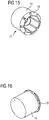
- FIG 15 illustrates a schematic perspective view of a cap element 16 and a support element 18 of the push-in-push-out control knob 10 according to the preferred embodiment of the present invention.
- FIG 16 illustrates a further schematic perspective view of the cap element 16 and the support element 18 of the push-in-push-out control knob according to the preferred embodiment of the present invention.
- FIG 15 and 16 clarify that the cap element 16 and the support element 18 form a control knob.
- the cap element 16 and the support element 18 are formed as a single-piece part.
- FIG 17 illustrates a schematic exploded perspective view of the push-in-push-out control knob 10 according to the prior art.
- the push-in-push-out control knob 10 comprises a proper control knob 32, a guiding ring 34, a housing 22 with flange and a switch mechanism 26.
- the push-in-push-out control knob 10 is assembled at the control panel 30 of the domestic appliance from the front side. Said push-in-push-out control knob 10 wobbles, when it is gripped by the user.
- FIG 18 illustrates a schematic exploded perspective view of a further push-in-push-out control knob 10 according to the prior art.
- the push-in-push-out control knob 10 comprises the proper control knob 32, the guiding ring 34, the housing 22 with flange, a rear knob part 36 and the switch mechanism 26.
- the push-in-push-out control knob 10 is assembled at the control panel 30 of the domestic appliance from the rear side.
- the assembling of said push-in-push-out control knob 10 at the control panel 30 is complex, since other control knobs are assembled from the front side of the control panel 30.
Landscapes
- Engineering & Computer Science (AREA)
- Chemical & Material Sciences (AREA)
- Combustion & Propulsion (AREA)
- Mechanical Engineering (AREA)
- General Engineering & Computer Science (AREA)
- Physics & Mathematics (AREA)
- General Physics & Mathematics (AREA)
- Automation & Control Theory (AREA)
- Push-Button Switches (AREA)
Abstract
The present invention relates to a push-in-push-out control knob (10) for a domestic appliance, in particular for a cooking appliance. The push-in-push-out control knob (10) is attached or attachable at a cut-out in a control panel (30) of the domestic appliance. The push-in-push-out control knob (10) comprises an outer component (12) and an inner component (14). The outer component (12) is arranged or arrangeable at a front side of the control panel (30). The inner component (14) is arranged or arrangeable at a rear side of the control panel (30). The inner component (14) includes a housing (22) and a ring (24). The ring (24) is arranged or arrangeable within a front opening of the housing (22), so that the ring (24) is form-fit with said front opening. The outer component (12) includes a support element (18) engaging or engageable behind the ring (24).
Description
- The present invention relates to a push-in-push-out control knob for a domestic appliance. In particular, the present invention relates to a push-in-push-out control knob for a cooking appliance. Further, the present invention relates to a domestic appliance.
- A push-in-push-out control knob is arranged within a control panel of a domestic appliance. The push-in-push-out control knob is counter-sunk in the control panel, when said push-in-push-out control knob is not in use. In contrast, the push-in-push-out control knob protrudes out of the control panel, when said push-in-push-out control knob is in use. Usually, the push-in-push-out control knob is rotatable in the protruding state.
-
FIG 17 illustrates a schematic exploded perspective view of the push-in-push-outcontrol knob 10 according to the prior art. The push-in-push-outcontrol knob 10 comprises aproper control knob 32, a guidingring 34, ahousing 22 with a flange and aswitch mechanism 26. The push-in-push-outcontrol knob 10 is assembled at thecontrol panel 30 of the domestic appliance from the front side. However, the push-in-push-out control knob 10 wobbles, when it is gripped by the user. -
FIG 18 illustrates a schematic exploded perspective view of a further push-in-push-outcontrol knob 10 according to the prior art. The push-in-push-outcontrol knob 10 comprises theproper control knob 32, the guidingring 34, thehousing 22 with flange, arear knob part 36 and theswitch mechanism 26. The push-in-push-outcontrol knob 10 is assembled at thecontrol panel 30 of the domestic appliance from the rear side. However, the assembling of the push-in-push-outcontrol knob 10 at thecontrol panel 30 is complex, since other control knobs are assembled from the front side of thecontrol panel 30. - It is an object of the present invention to provide a push-in-push-out control knob for a domestic appliance, which reduces wobbling and is assembled by low complexity.
- The object is achieved by the push-in-push-out control knob for a domestic appliance according to claim 1.
- According to the present invention a push-in-push-out control knob for a domestic appliance, in particular for a cooking appliance, is provided, wherein:
- the push-in-push-out control knob is attached or attachable at a cut-out in a control panel of the domestic appliance,
- the push-in-push-out control knob comprises an outer component and an inner component,
- the outer component is arranged or arrangeable at a front side of the control panel,
- the inner component is arranged or arrangeable at a rear side of the control panel,
- the inner component includes a housing and a ring,
- the ring is arranged or arrangeable within a front opening of the housing, so that the ring is form-fit with said front opening, and
- the outer component includes a support element engaging or engageable behind the ring.
- The core of the present invention is the ring in the front opening of the housing, which is engaged from behind by the support element. The ring reduces wobbling of the push-in-push-out control knob. Further, the push-in-push-out control knob is assembled by low complexity, since the outer component is arranged at the front side of the control panel, while the inner component is arranged at the rear side of the control panel.
- Preferably, the support element includes at least two snap-in hooks for engaging behind the ring, wherein said snap-in hooks form an enlarging of the support element.
- Further, the support element may include at least two wings extending along a push direction of the push-in-push-out control knob, wherein at least one snap-in hook is formed at a rear distal end of said wing.
- In particular, a plurality of snap-in hooks extends around the circumference of the support element and forms the enlarging of said support element.
- Moreover, the outer component may include a spring mechanism providing a force for pressing the support element, particularly the snap-in hooks, against the ring.
- Additionally, the inner component may include a switch mechanism, wherein preferably said switch mechanism is connected or connectable to the spring mechanism of the outer component. For example, the switch mechanism is a switch, a thermostat, an encoder or any input command device.
- Preferably, the outer component includes a cap element enclosing partially the support element, so that the cap element and the support element form a control knob.
- For example, the cap element is made of metal or plastics.
- Alternatively, the support element may form a control knob.
- Further, the push-in-push-out control knob may be rotatable around a rotation axis perpendicular to the plane of the control panel, wherein the push-in-push-out control knob is moveable along said rotation axis between a protruding state and a countersunk state.
- In particular, the wings form a cylindrical surface of the support element and extend parallel to the rotation axis of the push-in-push-out control knob.
- Preferably, the push-in-push-out control knob is attachable at a circular cut-out in the control panel of the domestic appliance, wherein the diameter of the ring is marginally bigger than the diameter of said circular cut-out. There is radial tolerance between the push-in-push-out control knob and the circular cut-out in the control panel.
- Furthermore, the present invention relates to a domestic appliance, in particular a cooking appliance, wherein the domestic appliance comprises at least one push-in-push-out control knob mentioned above.
- Further, the domestic appliance may comprise at least one control panel including at least one cut-out, wherein the push-in-push-out control knob is attached or attachable at said cut-out in the control panel of the domestic appliance.
- Moreover, the diameter of the cut-out in the control panel may be marginally smaller than the diameter of the ring of the push-in-push-out control knob, wherein preferably the cut-out in the control panel is circular.
- Novel and inventive features of the present invention are set forth in the appended claims.
- The present invention will be described in further detail with reference to the drawing, in which
- FIG 1
- illustrates a schematic perspective view of an outer component of a push-in-push-out control knob according to a preferred embodiment of the present invention,
- FIG 2
- illustrates a schematic exploded perspective view of the outer component of the push-in-push-out control knob according to the preferred embodiment of the present invention,
- FIG 3
- illustrates a schematic perspective view of another example of the outer component of the push-in-push-out control knob according to the preferred embodiment of the present invention,
- FIG 4
- illustrates a schematic exploded perspective view of the other example of the outer component of the push-in-push-out control knob according to the preferred embodiment of the present invention,
- FIG 5
- illustrates a schematic perspective view of an inner component of the push-in-push-out control knob according to the preferred embodiment of the present invention,
- FIG 6
- illustrates a schematic exploded perspective view of the inner component of the push-in-push-out control knob according to the preferred embodiment of the present invention,
- FIG 7
- illustrates a schematic perspective view of another example of the inner component of the push-in-push-out control knob according to the preferred embodiment of the present invention,
- FIG 8
- illustrates a schematic exploded perspective view of the other example of the inner component of the push-in-push-out control knob according to the preferred embodiment of the present invention,
- FIG 9
- illustrates a schematic sectional side view of the push-in-push-out control knob assembled in a control panel according to the preferred embodiment of the present invention,
- FIG 10
- illustrates a schematic perspective view of the push-in-push-out control knob assembled in the control panel according to the preferred embodiment of the present invention,
- FIG 11
- illustrates a schematic exploded perspective view of the push-in-push-out control knob assembled in the control panel according to the preferred embodiment of the present invention,
- FIG 12
- illustrates a schematic sectional side view of the push-in-push-out control knob assembled in the control panel according to the preferred embodiment of the present invention,
- FIG 13
- illustrates a schematic perspective view of the outer component of the push-in-push-out control knob according to the preferred embodiment of the present invention,
- FIG 14
- illustrates a schematic exploded perspective view of the outer component of the push-in-push-out control knob according to the preferred embodiment of the present invention,
- FIG 15
- illustrates a schematic perspective view of a cap element and a support element of the push-in-push-out control knob according to the preferred embodiment of the present invention,
- FIG 16
- illustrates a further schematic perspective view of the cap element and the support element of the push-in-push-out control knob according to the preferred embodiment of the present invention,
- FIG 17
- illustrates a schematic exploded perspective view of the push-in-push-out control knob according to the prior art, and
- FIG 18
- illustrates a schematic exploded perspective view of a further push-in-push-out control knob according to the prior art.
-
FIG 1 illustrates a schematic perspective view of anouter component 12 of a push-in-push-outcontrol knob 10 according to a preferred embodiment of the present invention. - The
outer component 12 of the push-in-push-outcontrol knob 10 comprises acap element 16, asupport element 18 and aspring mechanism 20. Thecap element 16 is substantially cylindrical and includes a closed face side and an open face side. Thesupport element 18 is also substantially cylindrical and includes a plurality of elastic wings. Said wings extend on the curved surface and along the symmetry axis of thesupport element 18. Each wing includes a snap-in hook at the distal end of said wing. The snap-in hooks form an enlarging of thesupport element 18. Said enlarging extends in circumferential direction of thesupport element 18. Except the enlarging thesupport element 18 is completely enclosed by thecap element 16. Thespring mechanism 20 is partially received by thecap element 16 and thesupport element 18. -
FIG 2 illustrates a schematic exploded perspective view of theouter component 12 of the push-in-push-outcontrol knob 10 according to the preferred embodiment of the present invention. - The structures of the
support element 18 andspring mechanism 20 are clarified inFIG 2 . Thespring mechanism 20 is partially received by thecap element 16. Thesupport element 18 is pressed between saidspring mechanism 20 andcap element 16. In this example, thecap element 16 is made at least partially of metal, while thesupport element 18 is made of plastics. Preferably, the frontal part of thecap element 16 as shown in the left region offigure 2 is formed as a frontal cap while the remaining part of thecap element 16 can be made of plastics and can be adapted to receive said frontal cap, wherein the frontal cap can be made of plastics or preferably of metal. Alternatively, thesupport element 18 may be provided without wings. Still in alternative, the wings can be embodied directly on the cap element and thesupport element 18 can be left away. -
FIG 3 illustrates a schematic perspective view of another example of theouter component 12 of the push-in-push-outcontrol knob 10 according to the preferred embodiment of the present invention. Theouter component 12 inFIG 3 is similar as theouter component 12 ofFIG 1 and 2 . However, thecap element 16 inFIG 3 is made of plastics. -
FIG 4 illustrates a schematic exploded perspective view of the other example of theouter component 12 of the push-in-push-outcontrol knob 10 according to the preferred embodiment of the present invention. Theouter component 12 inFIG 4 includes thecap element 16 made of plastics. -
FIG 5 illustrates a schematic perspective view of aninner component 14 of the push-in-push-outcontrol knob 10 according to the preferred embodiment of the present invention. - The
inner component 14 comprises ahousing 22 and aring 24. Further, theinner component 14 comprises aswitch mechanism 26, which is not shown inFIG 5 . Substantially, thehousing 22 is a pipe section with a flange. Thering 24 is enclosed by said flange. The flange is attachable at a rear side of acontrol panel 30. In this example, the flange is attachable at a rear side of acontrol panel 30 made of metal. Alternatively, theinner component 14 may be formed as a single-piece part. -
FIG 6 illustrates a schematic exploded perspective view of theinner component 14 of the push-in-push-outcontrol knob 10 according to the preferred embodiment of the present invention. The structure and size of thering 24 is clarified inFIG 6 . -
FIG 7 illustrates a schematic perspective view of another example of theinner component 14 of the push-in-push-outcontrol knob 10 according to the preferred embodiment of the present invention. - The
inner component 14 comprises thehousing 22 and thering 24. Moreover, theinner component 14 comprises theswitch mechanism 26, which is not shown inFIG 7 . Thehousing 22 is substantially formed as pipe section with flange. Thering 24 is enclosed by said flange. In this example, the flange is attachable at a rear side of acontrol panel 30 made of glass. Alternatively, theinner component 14 may be formed as a single-piece part. -
FIG 8 illustrates a schematic exploded perspective view of the other example of theinner component 14 of the push-in-push-outcontrol knob 10 according to the preferred embodiment of the present invention. The flange of the housing is attachable at the rear side of thecontrol panel 30 made of glass. -
FIG 9 illustrates a schematic sectional side view of the push-in-push-outcontrol knob 10 assembled in thecontrol panel 30 according to the preferred embodiment of the present invention. The push-in-push-outcontrol knob 10 is assembled in a circular cut-out of thecontrol panel 30. - The
first component 12 of the push-in-push-outcontrol knob 10 is assembled from the front side of thecontrol panel 30, while thesecond component 14 of the push-in-push-outcontrol knob 10 is assembled from the rear side of saidcontrol panel 30. - The flange of the
housing 22 is aligned at the rear side of saidcontrol panel 30. Theswitch mechanism 26 is arranged inside saidhousing 22. Thespring mechanism 20 is arranged substantially inside thecap element 16 and thesupport element 18. Thering 24 is enclosed by the front portion of thehousing 22. Thecap element 16 and thesupport element 18 form factually a single-piece part. - The
cap element 16 and thesupport element 18 penetrate thering 24, so that the snap-in hooks of thesupport element 18 engage with the rear portion of saidring 24. Thesupport element 18 engages behind thering 24. The force provided by thespring mechanism 20 presses the snap-in hooks of thesupport element 18 against the rear portion of thering 24. By this way the wobbling of the push-in-push-outcontrol knob 10 is reduced. - The properties of the
ring 24 provide a self-adjusting arrangement of thecap element 16 and thesupport element 18 in the cut-out of thecontrol panel 30. -
FIG 10 illustrates a schematic perspective view of the push-in-push-outcontrol knob 10 assembled in acontrol panel 30 according to the preferred embodiment of the present invention. - The
first component 12 of the push-in-push-outcontrol knob 10, i.e. thecap element 16 and thesupport element 18, is arranged at the front side of thecontrol panel 30, while thesecond component 14 of the push-in-push-outcontrol knob 10, i.e. thehousing 22 and theswitch mechanism 26, is arranged at the rear side of saidcontrol panel 30. Thering 24 and thespring mechanism 20 are arranged within the cut-out of thecontrol panel 30. -
FIG 11 illustrates a schematic exploded perspective view of the push-in-push-outcontrol knob 10 assembled in thecontrol panel 30 according to the preferred embodiment of the present invention. - The
cap element 16, thesupport element 18 and thespring mechanism 20 of the push-in-push-outcontrol knob 10 are assembled from the front side of thecontrol panel 30. In contrast, thehousing 22, thering 24 and theswitch mechanism 26 of the push-in-push-outcontrol knob 10 are assembled from the rear side of saidcontrol panel 30. - The
switch mechanism 26 is fixed at thehousing 22 byscrews 28. Thering 24 is inserted into the front portion of thehousing 22 as shown inFIG 5 and7 . Thesecond component 14 of the push-in-push-outcontrol knob 10 is aligned at the rear side of the cut-out in thecontrol panel 30, while thefirst component 14 of the push-in-push-outcontrol knob 10 is aligned at the front side of said cut-out in thecontrol panel 30. - The
cap element 16 and thesupport element 18 penetrate thering 24 in the cut-out in thecontrol panel 30, so that the snap-in hooks of thesupport element 18 engage with the rear portion of saidring 24. The force provided by thespring mechanism 20 presses the snap-in hooks of thesupport element 18 against the rear portion of thering 24, so that the wobbling of the push-in-push-outcontrol knob 10 is reduced. -
FIG 12 illustrates a schematic sectional side view of the push-in-push-outcontrol knob 10 assembled in thecontrol panel 30 according to the preferred embodiment of the present invention. - The
housing 22 is aligned at the rear side of thecontrol panel 30. Theswitch mechanism 26 is arranged at saidhousing 22. Thespring mechanism 20 is arranged substantially inside thecap element 16 and thesupport element 18. Thering 24 is behind the cut-out in thecontrol panel 30. - The
cap element 16 and thesupport element 18 penetrate thering 24. The snap-in hooks of thesupport element 18 are engaged with the rear portion of saidring 24. The force provided by thespring mechanism 20 presses the snap-in hooks of thesupport element 18 against the rear portion of thering 24. -
FIG 13 illustrates a schematic perspective view of theouter component 12 of the push-in-push-outcontrol knob 10 according to the preferred embodiment of the present invention. - The
outer component 12 of the push-in-push-outcontrol knob 10 comprises thecap element 16, thesupport element 18 and thespring mechanism 20. Thecap element 16 is substantially cylindrical and includes one closed face side and one open face side. Thecap element 16 encloses thesupport element 18 completely except the snap-in hooks. The snap-in hooks form the enlarging of thesupport element 18. Said enlarging extends circumferentially around theouter component 12 of the push-in-push-outcontrol knob 10. Thespring mechanism 20 is partially received by thecap element 16 and thesupport element 18. -
FIG 14 illustrates a schematic exploded perspective view of theouter component 12 of the push-in-push-outcontrol knob 10 according to the preferred embodiment of the present invention. - The structures of the
support element 18 andspring mechanism 20 are clearly shown inFIG 14 . Thespring mechanism 20 is partially received by thesupport element 18. In turn, thesupport element 18, except the snap-in hooks, is received by thecap element 16. -
FIG 15 illustrates a schematic perspective view of acap element 16 and asupport element 18 of the push-in-push-outcontrol knob 10 according to the preferred embodiment of the present invention. -
FIG 16 illustrates a further schematic perspective view of thecap element 16 and thesupport element 18 of the push-in-push-out control knob according to the preferred embodiment of the present invention. -
FIG 15 and 16 clarify that thecap element 16 and thesupport element 18 form a control knob. Alternatively, thecap element 16 and thesupport element 18 are formed as a single-piece part. -
FIG 17 illustrates a schematic exploded perspective view of the push-in-push-outcontrol knob 10 according to the prior art. The push-in-push-outcontrol knob 10 comprises aproper control knob 32, a guidingring 34, ahousing 22 with flange and aswitch mechanism 26. The push-in-push-outcontrol knob 10 is assembled at thecontrol panel 30 of the domestic appliance from the front side. Said push-in-push-outcontrol knob 10 wobbles, when it is gripped by the user. -
FIG 18 illustrates a schematic exploded perspective view of a further push-in-push-outcontrol knob 10 according to the prior art. The push-in-push-outcontrol knob 10 comprises theproper control knob 32, the guidingring 34, thehousing 22 with flange, arear knob part 36 and theswitch mechanism 26. The push-in-push-outcontrol knob 10 is assembled at thecontrol panel 30 of the domestic appliance from the rear side. The assembling of said push-in-push-outcontrol knob 10 at thecontrol panel 30 is complex, since other control knobs are assembled from the front side of thecontrol panel 30. - Although an illustrative embodiment of the present invention has been described herein with reference to the accompanying drawings, it is to be understood that the present invention is not limited to that precise embodiment, and that various other changes and modifications may be affected therein by one skilled in the art without departing from the scope or spirit of the invention. All such changes and modifications are intended to be included within the scope of the invention as defined by the appended claims.
-
- 10
- push-in-push-out control knob
- 12
- outer component
- 14
- inner component
- 16
- cap element
- 18
- support element
- 20
- spring mechanism
- 22
- housing
- 24
- ring
- 26
- switch mechanism
- 28
- screw
- 30
- control panel
- 32
- control knob
- 34
- guiding ring
- 36
- rear knob part
Claims (15)
- A push-in-push-out control knob (10) for a domestic appliance, in particular for a cooking appliance, wherein:- the push-in-push-out control knob (10) is attached or attachable at a cut-out in a control panel (30) of the domestic appliance,- the push-in-push-out control knob (10) comprises an outer component (12) and an inner component (14),- the outer component (12) is arranged or arrangeable at a front side of the control panel (30),- the inner component (14) is arranged or arrangeable at a rear side of the control panel (30),- the inner component (14) includes a housing (22) and a ring (24),- the ring (24) is arranged or arrangeable within a front opening of the housing (22), so that the ring (24) is form-fit with said front opening, and- the outer component (12) includes a support element (18) engaging or engageable behind the ring (24).
- The push-in-push-out control knob according to claim 1,
characterised in that
the support element (18) includes at least two snap-in hooks for engaging behind the ring (24), wherein said snap-in hooks form an enlarging of the support element (18). - The push-in-push-out control knob according to claim 2,
characterised in that
the support element (18) includes at least two wings extending along a push direction of the push-in-push-out control knob (10), wherein at least one snap-in hook is formed at a rear distal end of said wing. - The push-in-push-out control knob according to claim 2 or 3,
characterised in that
a plurality of snap-in hooks extends around the circumference of the support element (18) and forms the enlarging of said support element (18). - The push-in-push-out control knob according to any one of the preceding claims,
characterised in that
the outer component (12) includes a spring mechanism (20) providing a force for pressing the support element (18), particularly the snap-in hooks, against the ring (24). - The push-in-push-out control knob according to any one of the preceding claims,
characterised in that
the inner component (14) includes a switch mechanism (26), wherein preferably said switch mechanism (26) is connected or connectable to the spring mechanism (20) of the outer component (12). - The push-in-push-out control knob according to claim 6,
characterised in that
the switch mechanism (26) is a switch, a thermostat, an encoder or any input command device. - The push-in-push-out control knob according to any one of the preceding claims,
characterised in that
the outer component (14) includes a cap element (16) enclosing partially the support element (18), so that the cap element (16) and the support element (18) form a control knob, wherein preferably said cap element (16) is made at least in part of metal or plastics, still preferably wherein the cap element (16) is made of plastics and is adapted to receive a frontal cap that can be made of plastics or of metal. - The push-in-push-out control knob according to any one of the claims 1 to 7,
characterised in that
the support element (18) forms a control knob. - The push-in-push-out control knob according to any one of the preceding claims,
characterised in that
the push-in-push-out control knob (10) is rotatable around a rotation axis perpendicular to the plane of the control panel (30), wherein the push-in-push-out control knob (10) is moveable along said rotation axis between a protruding state and a countersunk state. - The push-in-push-out control knob according to any one of the claims 3 to 10,
characterised in that
the wings form a cylindrical surface of the support element (18) and extend parallel to the rotation axis of the push-in-push-out control knob (10). - The push-in-push-out control knob according to any one of the preceding claims,
characterised in that
the push-in-push-out control knob (10) is attachable at a circular cut-out in the control panel (30) of the domestic appliance, wherein the diameter of the ring (24) is marginally bigger than the diameter of said circular cut-out. - A domestic appliance, in particular a cooking appliance,
characterised in that
the domestic appliance comprises at least one push-in-push-out control knob (10) according to any one of the preceding claims. - The domestic appliance according to claim 13,
characterised in that
the domestic appliance comprises at least one control panel (30) including at least one cut-out, wherein the push-in-push-out control knob (10) is attached or attachable at said cut-out in the control panel (30) of the domestic appliance. - The domestic appliance according to claim 14,
characterised in that
the diameter of the cut-out in the control panel (30) is marginally smaller than the diameter of the ring (24) of the push-in-push-out control knob (10), wherein preferably the cut-out in the control panel (30) is circular.
Priority Applications (1)
| Application Number | Priority Date | Filing Date | Title |
|---|---|---|---|
| EP18203283.9A EP3647662A1 (en) | 2018-10-30 | 2018-10-30 | Push-in push-out control knob for a domestic appliance |
Applications Claiming Priority (1)
| Application Number | Priority Date | Filing Date | Title |
|---|---|---|---|
| EP18203283.9A EP3647662A1 (en) | 2018-10-30 | 2018-10-30 | Push-in push-out control knob for a domestic appliance |
Publications (1)
| Publication Number | Publication Date |
|---|---|
| EP3647662A1 true EP3647662A1 (en) | 2020-05-06 |
Family
ID=64048724
Family Applications (1)
| Application Number | Title | Priority Date | Filing Date |
|---|---|---|---|
| EP18203283.9A Withdrawn EP3647662A1 (en) | 2018-10-30 | 2018-10-30 | Push-in push-out control knob for a domestic appliance |
Country Status (1)
| Country | Link |
|---|---|
| EP (1) | EP3647662A1 (en) |
Cited By (1)
| Publication number | Priority date | Publication date | Assignee | Title |
|---|---|---|---|---|
| DE102024108388A1 (en) * | 2024-03-25 | 2025-09-25 | Hansgrohe Se | Operating handle device for a thermostatic valve and wall installation device |
Citations (4)
| Publication number | Priority date | Publication date | Assignee | Title |
|---|---|---|---|---|
| US5384442A (en) * | 1993-01-05 | 1995-01-24 | Whirlpool Corporation | Control knob assembly for a cooking appliance |
| EP2410547A1 (en) * | 2010-07-22 | 2012-01-25 | Miele & Cie. KG | Household appliance with a lowerable operating knob unit |
| EP2485111A1 (en) * | 2011-02-04 | 2012-08-08 | Whirlpool Corporation | Improved retractable control device for domestic appliance |
| DE102012222146A1 (en) * | 2012-12-04 | 2014-06-18 | BSH Bosch und Siemens Hausgeräte GmbH | Control element for operating device of household appliance e.g. microwave apparatus, to prepare food products, has control element cap moving toward longitudinal axis of element and arranged on bent supporting surface against guide surface |
-
2018
- 2018-10-30 EP EP18203283.9A patent/EP3647662A1/en not_active Withdrawn
Patent Citations (4)
| Publication number | Priority date | Publication date | Assignee | Title |
|---|---|---|---|---|
| US5384442A (en) * | 1993-01-05 | 1995-01-24 | Whirlpool Corporation | Control knob assembly for a cooking appliance |
| EP2410547A1 (en) * | 2010-07-22 | 2012-01-25 | Miele & Cie. KG | Household appliance with a lowerable operating knob unit |
| EP2485111A1 (en) * | 2011-02-04 | 2012-08-08 | Whirlpool Corporation | Improved retractable control device for domestic appliance |
| DE102012222146A1 (en) * | 2012-12-04 | 2014-06-18 | BSH Bosch und Siemens Hausgeräte GmbH | Control element for operating device of household appliance e.g. microwave apparatus, to prepare food products, has control element cap moving toward longitudinal axis of element and arranged on bent supporting surface against guide surface |
Cited By (1)
| Publication number | Priority date | Publication date | Assignee | Title |
|---|---|---|---|---|
| DE102024108388A1 (en) * | 2024-03-25 | 2025-09-25 | Hansgrohe Se | Operating handle device for a thermostatic valve and wall installation device |
Similar Documents
| Publication | Publication Date | Title |
|---|---|---|
| US5509174A (en) | Appliance knob and bezel assembly | |
| CN109844330B (en) | Connecting device | |
| US4920823A (en) | Rotary knob for control devices or the like | |
| GB2130438A (en) | Rotary knob | |
| EP3165990A1 (en) | Command device for electrical appliances, in particular for ovens or stovetops | |
| US8534160B2 (en) | Retractable control device for domestic appliance | |
| CN116529547B (en) | Quick release handle comprising light and sound | |
| EP3462092B1 (en) | A cooking device having a control knob | |
| EP3505829A1 (en) | A cooking appliance having a control knob | |
| US9523997B2 (en) | Push-button switch, selector switch, and fixing component therefor | |
| KR102186601B1 (en) | Appliance having knob assembly | |
| US6720513B2 (en) | Rotary switch configuration for a household appliance | |
| EP0927426B2 (en) | Control knob used for household appliances | |
| US3430515A (en) | Adjustment knob for electric device | |
| US3386127A (en) | Control knob connecting means | |
| AU2023281744B2 (en) | Household appliance | |
| US5101189A (en) | Adjustable electric thermostat | |
| CN210320811U (en) | Hinge assembly for refrigeration appliance and refrigeration appliance | |
| CN114541874A (en) | Joystick with variable-length entrainer | |
| WO2022119512A1 (en) | An oven with thermostat setting rotary knob | |
| US20070017308A1 (en) | Manipulation device of microwave oven | |
| EP4057104A1 (en) | A rotary knob assembly for household appliances | |
| EP2868978A1 (en) | A domestic appliance fitted with a button socket | |
| CN220038547U (en) | Control device and household appliance | |
| CN212277072U (en) | Timer knob structure and oven |
Legal Events
| Date | Code | Title | Description |
|---|---|---|---|
| PUAI | Public reference made under article 153(3) epc to a published international application that has entered the european phase |
Free format text: ORIGINAL CODE: 0009012 |
|
| STAA | Information on the status of an ep patent application or granted ep patent |
Free format text: STATUS: THE APPLICATION HAS BEEN PUBLISHED |
|
| AK | Designated contracting states |
Kind code of ref document: A1 Designated state(s): AL AT BE BG CH CY CZ DE DK EE ES FI FR GB GR HR HU IE IS IT LI LT LU LV MC MK MT NL NO PL PT RO RS SE SI SK SM TR |
|
| AX | Request for extension of the european patent |
Extension state: BA ME |
|
| STAA | Information on the status of an ep patent application or granted ep patent |
Free format text: STATUS: THE APPLICATION IS DEEMED TO BE WITHDRAWN |
|
| 18D | Application deemed to be withdrawn |
Effective date: 20201107 |