EP3647630A1 - Gearbox with integrated submersible lubricant pump - Google Patents
Gearbox with integrated submersible lubricant pump Download PDFInfo
- Publication number
- EP3647630A1 EP3647630A1 EP19205355.1A EP19205355A EP3647630A1 EP 3647630 A1 EP3647630 A1 EP 3647630A1 EP 19205355 A EP19205355 A EP 19205355A EP 3647630 A1 EP3647630 A1 EP 3647630A1
- Authority
- EP
- European Patent Office
- Prior art keywords
- lubricant
- bearing
- casing
- interior
- gearbox
- Prior art date
- Legal status (The legal status is an assumption and is not a legal conclusion. Google has not performed a legal analysis and makes no representation as to the accuracy of the status listed.)
- Granted
Links
Images


Classifications
-
- F—MECHANICAL ENGINEERING; LIGHTING; HEATING; WEAPONS; BLASTING
- F16—ENGINEERING ELEMENTS AND UNITS; GENERAL MEASURES FOR PRODUCING AND MAINTAINING EFFECTIVE FUNCTIONING OF MACHINES OR INSTALLATIONS; THERMAL INSULATION IN GENERAL
- F16H—GEARING
- F16H57/00—General details of gearing
- F16H57/04—Features relating to lubrication or cooling or heating
- F16H57/0434—Features relating to lubrication or cooling or heating relating to lubrication supply, e.g. pumps; Pressure control
- F16H57/0436—Pumps
-
- B—PERFORMING OPERATIONS; TRANSPORTING
- B64—AIRCRAFT; AVIATION; COSMONAUTICS
- B64D—EQUIPMENT FOR FITTING IN OR TO AIRCRAFT; FLIGHT SUITS; PARACHUTES; ARRANGEMENT OR MOUNTING OF POWER PLANTS OR PROPULSION TRANSMISSIONS IN AIRCRAFT
- B64D35/00—Transmitting power from power plants to propellers or rotors; Arrangements of transmissions
- B64D35/04—Transmitting power from power plants to propellers or rotors; Arrangements of transmissions characterised by the transmission driving a plurality of propellers or rotors
-
- F—MECHANICAL ENGINEERING; LIGHTING; HEATING; WEAPONS; BLASTING
- F16—ENGINEERING ELEMENTS AND UNITS; GENERAL MEASURES FOR PRODUCING AND MAINTAINING EFFECTIVE FUNCTIONING OF MACHINES OR INSTALLATIONS; THERMAL INSULATION IN GENERAL
- F16H—GEARING
- F16H57/00—General details of gearing
- F16H57/02—Gearboxes; Mounting gearing therein
- F16H57/038—Gearboxes for accommodating bevel gears
-
- F—MECHANICAL ENGINEERING; LIGHTING; HEATING; WEAPONS; BLASTING
- F16—ENGINEERING ELEMENTS AND UNITS; GENERAL MEASURES FOR PRODUCING AND MAINTAINING EFFECTIVE FUNCTIONING OF MACHINES OR INSTALLATIONS; THERMAL INSULATION IN GENERAL
- F16H—GEARING
- F16H57/00—General details of gearing
- F16H57/04—Features relating to lubrication or cooling or heating
- F16H57/0402—Cleaning of lubricants, e.g. filters or magnets
- F16H57/0404—Lubricant filters
-
- F—MECHANICAL ENGINEERING; LIGHTING; HEATING; WEAPONS; BLASTING
- F16—ENGINEERING ELEMENTS AND UNITS; GENERAL MEASURES FOR PRODUCING AND MAINTAINING EFFECTIVE FUNCTIONING OF MACHINES OR INSTALLATIONS; THERMAL INSULATION IN GENERAL
- F16H—GEARING
- F16H57/00—General details of gearing
- F16H57/04—Features relating to lubrication or cooling or heating
- F16H57/042—Guidance of lubricant
- F16H57/0421—Guidance of lubricant on or within the casing, e.g. shields or baffles for collecting lubricant, tubes, pipes, grooves, channels or the like
- F16H57/0423—Lubricant guiding means mounted or supported on the casing, e.g. shields or baffles for collecting lubricant, tubes or pipes
-
- F—MECHANICAL ENGINEERING; LIGHTING; HEATING; WEAPONS; BLASTING
- F16—ENGINEERING ELEMENTS AND UNITS; GENERAL MEASURES FOR PRODUCING AND MAINTAINING EFFECTIVE FUNCTIONING OF MACHINES OR INSTALLATIONS; THERMAL INSULATION IN GENERAL
- F16H—GEARING
- F16H57/00—General details of gearing
- F16H57/04—Features relating to lubrication or cooling or heating
- F16H57/042—Guidance of lubricant
- F16H57/0421—Guidance of lubricant on or within the casing, e.g. shields or baffles for collecting lubricant, tubes, pipes, grooves, channels or the like
- F16H57/0424—Lubricant guiding means in the wall of or integrated with the casing, e.g. grooves, channels, holes
-
- F—MECHANICAL ENGINEERING; LIGHTING; HEATING; WEAPONS; BLASTING
- F16—ENGINEERING ELEMENTS AND UNITS; GENERAL MEASURES FOR PRODUCING AND MAINTAINING EFFECTIVE FUNCTIONING OF MACHINES OR INSTALLATIONS; THERMAL INSULATION IN GENERAL
- F16H—GEARING
- F16H57/00—General details of gearing
- F16H57/04—Features relating to lubrication or cooling or heating
- F16H57/0434—Features relating to lubrication or cooling or heating relating to lubrication supply, e.g. pumps; Pressure control
- F16H57/0441—Arrangements of pumps
-
- F—MECHANICAL ENGINEERING; LIGHTING; HEATING; WEAPONS; BLASTING
- F16—ENGINEERING ELEMENTS AND UNITS; GENERAL MEASURES FOR PRODUCING AND MAINTAINING EFFECTIVE FUNCTIONING OF MACHINES OR INSTALLATIONS; THERMAL INSULATION IN GENERAL
- F16H—GEARING
- F16H57/00—General details of gearing
- F16H57/04—Features relating to lubrication or cooling or heating
- F16H57/045—Lubricant storage reservoirs, e.g. reservoirs in addition to a gear sump for collecting lubricant in the upper part of a gear case
-
- F—MECHANICAL ENGINEERING; LIGHTING; HEATING; WEAPONS; BLASTING
- F16—ENGINEERING ELEMENTS AND UNITS; GENERAL MEASURES FOR PRODUCING AND MAINTAINING EFFECTIVE FUNCTIONING OF MACHINES OR INSTALLATIONS; THERMAL INSULATION IN GENERAL
- F16H—GEARING
- F16H57/00—General details of gearing
- F16H57/04—Features relating to lubrication or cooling or heating
- F16H57/0456—Lubrication by injection; Injection nozzles or tubes therefor
-
- F—MECHANICAL ENGINEERING; LIGHTING; HEATING; WEAPONS; BLASTING
- F16—ENGINEERING ELEMENTS AND UNITS; GENERAL MEASURES FOR PRODUCING AND MAINTAINING EFFECTIVE FUNCTIONING OF MACHINES OR INSTALLATIONS; THERMAL INSULATION IN GENERAL
- F16H—GEARING
- F16H57/00—General details of gearing
- F16H57/04—Features relating to lubrication or cooling or heating
- F16H57/0458—Oil-mist or spray lubrication; Means to reduce foam formation
- F16H57/046—Oil-mist or spray lubrication
-
- F—MECHANICAL ENGINEERING; LIGHTING; HEATING; WEAPONS; BLASTING
- F16—ENGINEERING ELEMENTS AND UNITS; GENERAL MEASURES FOR PRODUCING AND MAINTAINING EFFECTIVE FUNCTIONING OF MACHINES OR INSTALLATIONS; THERMAL INSULATION IN GENERAL
- F16H—GEARING
- F16H57/00—General details of gearing
- F16H57/04—Features relating to lubrication or cooling or heating
- F16H57/0467—Elements of gearings to be lubricated, cooled or heated
- F16H57/0469—Bearings or seals
- F16H57/0471—Bearing
-
- F—MECHANICAL ENGINEERING; LIGHTING; HEATING; WEAPONS; BLASTING
- F16—ENGINEERING ELEMENTS AND UNITS; GENERAL MEASURES FOR PRODUCING AND MAINTAINING EFFECTIVE FUNCTIONING OF MACHINES OR INSTALLATIONS; THERMAL INSULATION IN GENERAL
- F16H—GEARING
- F16H57/00—General details of gearing
- F16H57/04—Features relating to lubrication or cooling or heating
- F16H57/048—Type of gearings to be lubricated, cooled or heated
- F16H57/0493—Gearings with spur or bevel gears
-
- F—MECHANICAL ENGINEERING; LIGHTING; HEATING; WEAPONS; BLASTING
- F16—ENGINEERING ELEMENTS AND UNITS; GENERAL MEASURES FOR PRODUCING AND MAINTAINING EFFECTIVE FUNCTIONING OF MACHINES OR INSTALLATIONS; THERMAL INSULATION IN GENERAL
- F16N—LUBRICATING
- F16N7/00—Arrangements for supplying oil or unspecified lubricant from a stationary reservoir or the equivalent in or on the machine or member to be lubricated
- F16N7/36—Arrangements for supplying oil or unspecified lubricant from a stationary reservoir or the equivalent in or on the machine or member to be lubricated with feed by pumping action of the member to be lubricated or of a shaft of the machine; Centrifugal lubrication
- F16N7/366—Arrangements for supplying oil or unspecified lubricant from a stationary reservoir or the equivalent in or on the machine or member to be lubricated with feed by pumping action of the member to be lubricated or of a shaft of the machine; Centrifugal lubrication with feed by pumping action of a vertical shaft of the machine
-
- B—PERFORMING OPERATIONS; TRANSPORTING
- B64—AIRCRAFT; AVIATION; COSMONAUTICS
- B64C—AEROPLANES; HELICOPTERS
- B64C27/00—Rotorcraft; Rotors peculiar thereto
- B64C27/04—Helicopters
- B64C27/12—Rotor drives
- B64C27/14—Direct drive between power plant and rotor hub
-
- B—PERFORMING OPERATIONS; TRANSPORTING
- B64—AIRCRAFT; AVIATION; COSMONAUTICS
- B64C—AEROPLANES; HELICOPTERS
- B64C27/00—Rotorcraft; Rotors peculiar thereto
- B64C27/54—Mechanisms for controlling blade adjustment or movement relative to rotor head, e.g. lag-lead movement
- B64C27/78—Mechanisms for controlling blade adjustment or movement relative to rotor head, e.g. lag-lead movement in association with pitch adjustment of blades of anti-torque rotor
-
- B—PERFORMING OPERATIONS; TRANSPORTING
- B64—AIRCRAFT; AVIATION; COSMONAUTICS
- B64C—AEROPLANES; HELICOPTERS
- B64C27/00—Rotorcraft; Rotors peculiar thereto
- B64C27/82—Rotorcraft; Rotors peculiar thereto characterised by the provision of an auxiliary rotor or fluid-jet device for counter-balancing lifting rotor torque or changing direction of rotorcraft
-
- F—MECHANICAL ENGINEERING; LIGHTING; HEATING; WEAPONS; BLASTING
- F16—ENGINEERING ELEMENTS AND UNITS; GENERAL MEASURES FOR PRODUCING AND MAINTAINING EFFECTIVE FUNCTIONING OF MACHINES OR INSTALLATIONS; THERMAL INSULATION IN GENERAL
- F16H—GEARING
- F16H57/00—General details of gearing
- F16H57/02—Gearboxes; Mounting gearing therein
- F16H57/021—Shaft support structures, e.g. partition walls, bearing eyes, casing walls or covers with bearings
-
- F—MECHANICAL ENGINEERING; LIGHTING; HEATING; WEAPONS; BLASTING
- F16—ENGINEERING ELEMENTS AND UNITS; GENERAL MEASURES FOR PRODUCING AND MAINTAINING EFFECTIVE FUNCTIONING OF MACHINES OR INSTALLATIONS; THERMAL INSULATION IN GENERAL
- F16N—LUBRICATING
- F16N2210/00—Applications
- F16N2210/12—Gearings
-
- F—MECHANICAL ENGINEERING; LIGHTING; HEATING; WEAPONS; BLASTING
- F16—ENGINEERING ELEMENTS AND UNITS; GENERAL MEASURES FOR PRODUCING AND MAINTAINING EFFECTIVE FUNCTIONING OF MACHINES OR INSTALLATIONS; THERMAL INSULATION IN GENERAL
- F16N—LUBRICATING
- F16N2210/00—Applications
- F16N2210/14—Bearings
Definitions
- the subject matter disclosed herein generally relates to the art of vehicles and, more particularly, to a gear box having an integrated submersible pump for a vehicle.
- Vehicles include gearboxes that may transfer energy from a prime mover into another system.
- a main gearbox may transmit energy from the prime mover to a main rotor system.
- Rotorcraft may also possess a tail gearbox that transmits energy from the prime mover to a tail rotor assembly.
- Many gearboxes rely on centrifugal force generated by rotating components to splash lubricant onto bearings and other surfaces in need of lubricant.
- Other gearboxes may rely on external pumps.
- Orientation changes and other factors may contribute to a lack or near lack of lubrication on one or more rotating components. Poor lubrication leads to heat generation and excessive wear and premature failure.
- External pumps should meet Federal Aviation Regulation (FAR) Oil-Out requirements, in addition they require space which is often lacking for various gearbox configuration, particularly tail rotor gearboxes. Replacing bearings and/or other rotating components is a costly endeavor leading to lengthy down times for the vehicle impacting the usage and profitability of the aircraft. Accordingly, it would be desirable to provide a lubrication system that would provide a flow of lubricant to a rotating component regardless of vehicle orientation without adding to an overall footprint of a gearbox. Further it would be desirable to design such a system that could be designed into new gearboxes or that could be kitted to drop-in to present configurations.
- a gear box includes a casing having an interior.
- a rotating component is arranged in the interior of the casing.
- a bearing including a rotating element, and a fixed element is connected with the casing in the interior.
- a submersible pump is arranged in the interior of the casing.
- the submersible pump includes a first housing portion extending about the rotating component fixedly mounted to the casing at the interior.
- a second housing portion is fixedly mounted to the casing at the interior and is aligned with the first housing portion.
- the first and second housing portions form a lubricant reservoir which holds lubricant.
- An impeller is mounted to the rotating component and arranged in the lubricant reservoir.
- One of the first and second housing portions includes an outlet through which the pumped lubricant is directed toward the rotating element.
- a nozzle extends from the one of the first and second housing portions, the nozzle having a first end arranged at the outlet and fluidically exposed to the lubricant reservoir and a second end directed toward the bearing and through which the pumped lubricant is directed toward the rotating element of the bearing.
- a lubricant sump is arranged in the casing, the lubricant sump being fluidically connected with the lubricant reservoir.
- a screen is arranged between the lubricant sump and the lubricant reservoir.
- the rotating component comprises a pinion.
- the bearing comprises a tail rotor pitch change shaft bearing.
- a vehicle includes a body, a prime mover supported by the body, a rotating system mounted to the body, and a gearbox mechanically connected between the prime mover and the rotating system.
- the gearbox includes a casing having an interior.
- a rotating component is arranged in the interior of the casing.
- a bearing including a rotating element, and a fixed element is connected with the casing in the interior.
- a submersible pump is arranged in the interior of the casing.
- the submersible pump includes a first housing portion extending about the rotating component fixedly mounted to the casing at the interior.
- a second housing portion is fixedly mounted to the casing at the interior and is aligned with the first housing portion.
- the first and second housing portions form a lubricant reservoir which holds lubricant.
- An impeller is mounted to the rotating component and arranged in the lubricant reservoir.
- One of the first and second housing portions includes an outlet through which the pumped lubricant is directed toward the rotating element.
- a nozzle extends from the one of the first and second housing portions, the nozzle having a first end arranged at the outlet and fluidically exposed to the lubricant reservoir and a second end directed toward the bearing and through which the pumped lubricant is directed toward the rotating element of the bearing.
- a lubricant sump is arranged in the casing, the lubricant sump being fluidically connected with the lubricant reservoir.
- a screen is arranged between the lubricant sump and the lubricant reservoir.
- the rotating component comprises a pinion.
- the pinion is rotatably supported in the casing through a first bearing and a second bearing, the submersible pump being arranged between the first and second bearings.
- the bearing comprises a tail rotor pitch change shaft bearing.
- the body comprises a fuselage of a rotorcraft.
- the gearbox comprises a tail rotor gear box.
- a vertical takeoff and landing (VTOL) or rotary wing aircraft in accordance with an exemplary embodiment, is generally indicated at 10 in FIGS 1 and 2 .
- Rotary wing aircraft 10 including a fuselage 12 supported by an airframe 14.
- Rotary wing aircraft 10 includes a main rotor system 16, which rotates about a main rotor axis R.
- Main rotor system 16 includes a plurality of rotor blades 20 rotatable about a main rotor axis "R".
- Plurality of rotor blades 20 is mounted to a rotor hub 24 having a rotor head 26.
- Main rotor system 16 is driven by a gearbox 28 coupled to one or more prime movers, indicated generally at 30.
- Rotary wing aircraft 10 includes an extending tail 40 that supports a vertical stabilizer 42 and a horizontal stabilizer or stabilator 44.
- a tail rotor system 46 including a plurality of tail rotor blades, indicated generally at 48 is mounted to vertical stabilizer 42.
- tail rotor system 46 provides yaw control for rotary wing aircraft 10.
- Rotary wing aircraft 10 includes forward supports or landing gear, one of which is indicated at 52, that may be connected to a retractable or foldable support 53 arranged below a cabin portion (not separately labeled) of fuselage 12 and a rear support or wheel 52 that may be connected to a rear retractable or foldable support 55 supported at extending tail 40.
- rotary wing aircraft 10 may take on various forms including dual rotor systems, pusher prop systems, and the like.
- Tail rotor system 46 may be operatively coupled to gearbox 28 through a drive shaft (not shown) or through a system of drive shafts incorporating an intermediate gearbox (also not shown). More specifically, the drive shaft may extend from gearbox 28 to a tail gearbox 60.
- tail gear box 60 includes a housing 64 having an interior 66. Housing 64 supports a first rotating component 70 that may take the form of an input shaft such as a pinion gear 72. Housing 64 also supports a second rotating component 74 that may take the form of an output shaft 74 that is coupled to tail rotor system 46. Output shaft 74 is rotatably supported in housing 64 through an output shaft bearing 75.
- Output shaft 74 includes a hollow interior portion 78 that is receptive of a pitch change shaft 82 of tail rotor system 46.
- Pitch change shaft 82 is supported within hollow interior portion 78 through a pitch change shaft bearing 85 and may be selectively manipulated to change a pitch angle of tail rotor blades 48.
- a pitch change member 90 is connected to pitch change shaft 82 and selectively manipulated through a rotorcraft control system (not shown) to apply yaw control inputs to rotorcraft 10 through tail rotor system 46.
- Housing 64 includes an input shaft casing 96 that supports pinion gear 72 through a first bearing 98 and a second bearing 100.
- Input shaft casing 96 defines a lubricant sump 104 having a lubricant reservoir 106 that promotes lubrication of first and second bearings 98 and 100.
- a submersible pump 110 is arranged in lubricant sump 104.
- submersible pump 110 is disposed between first bearing 98 and second bearing 100. It should be understood that the submersible pump 110 may be arranged in other locations in the sump 104 and should not be considered as being limited the particular location shown, e.g., between two bearings 98, 100.
- submersible pump 110 operates to deliver a flow of lubricant onto pitch change bearing 85.
- submersible pump 110 may be configured to deliver a flow of lubricant onto other components either in conjunction with delivering lubricant to pitch change bearing 85 or as an alternative thereto.
- Submersible pump 110 is submerged in lubricant 112 within the sump 104.
- submersible pump 110 includes a first housing portion 114 that aligns with a second housing portion 115 within input shaft casing 96.
- First and second housing portions 114 and 115 are rotatably fixed relative to input shaft casing 96.
- An impeller 118 is disposed within first and second housing portions 114 and 115 and fixedly connected with input shaft 72, which rotates relative to the housing portions 114, 115.
- first housing portion 114 includes an inlet 128 and second housing portion 115 includes an outlet 130.
- a mesh screen 134 is be disposed at inlet 128 in the shown embodiment.
- Mesh screen 134 is configured to prevent any particles that could be entrained in lubricant residing in lubricant reservoir 106 from entering into submersible pump 110.
- the mesh screen 134 need not be used in all aspects of the invention.
- submersible pump 110 supports a nozzle 140 that directs a flow of lubricant created by the rotation of the impeller 118 towards pitch change bearing 85.
- Nozzle 140 includes a first end 144 fluidically connected with housing outlet 130 and a second end 146 that is directed at pitch change bearing 85. As noted herein second or outlet end 146 may be directed at other components. Further, it should be understood that multiple nozzles could be employed to guide lubricant onto multiple components.
- the exemplary embodiments describe a gearbox that is capable of directing lubricant onto one or more components regardless of aircraft orientation.
- the use of a pump and a nozzle(s) that are directed to particular components ensures that those components are provided with a selected amount of lubricant to enhance an overall operational life and reduce maintenance costs.
Landscapes
- Engineering & Computer Science (AREA)
- General Engineering & Computer Science (AREA)
- Mechanical Engineering (AREA)
- Chemical & Material Sciences (AREA)
- Oil, Petroleum & Natural Gas (AREA)
- Aviation & Aerospace Engineering (AREA)
- General Details Of Gearings (AREA)
Abstract
Description
- The subject matter disclosed herein generally relates to the art of vehicles and, more particularly, to a gear box having an integrated submersible pump for a vehicle.
- Vehicles include gearboxes that may transfer energy from a prime mover into another system. In a rotorcraft, a main gearbox may transmit energy from the prime mover to a main rotor system. Rotorcraft may also possess a tail gearbox that transmits energy from the prime mover to a tail rotor assembly. Many gearboxes rely on centrifugal force generated by rotating components to splash lubricant onto bearings and other surfaces in need of lubricant. Other gearboxes may rely on external pumps.
- Orientation changes and other factors may contribute to a lack or near lack of lubrication on one or more rotating components. Poor lubrication leads to heat generation and excessive wear and premature failure. External pumps should meet Federal Aviation Regulation (FAR) Oil-Out requirements, in addition they require space which is often lacking for various gearbox configuration, particularly tail rotor gearboxes. Replacing bearings and/or other rotating components is a costly endeavor leading to lengthy down times for the vehicle impacting the usage and profitability of the aircraft. Accordingly, it would be desirable to provide a lubrication system that would provide a flow of lubricant to a rotating component regardless of vehicle orientation without adding to an overall footprint of a gearbox. Further it would be desirable to design such a system that could be designed into new gearboxes or that could be kitted to drop-in to present configurations.
- According to an embodiment, a gear box includes a casing having an interior. A rotating component is arranged in the interior of the casing. A bearing including a rotating element, and a fixed element is connected with the casing in the interior. A submersible pump is arranged in the interior of the casing. The submersible pump includes a first housing portion extending about the rotating component fixedly mounted to the casing at the interior. A second housing portion is fixedly mounted to the casing at the interior and is aligned with the first housing portion. The first and second housing portions form a lubricant reservoir which holds lubricant. An impeller is mounted to the rotating component and arranged in the lubricant reservoir. One of the first and second housing portions includes an outlet through which the pumped lubricant is directed toward the rotating element.
- In addition to one or more of the features described above, or as an alternative, in further embodiments a nozzle extends from the one of the first and second housing portions, the nozzle having a first end arranged at the outlet and fluidically exposed to the lubricant reservoir and a second end directed toward the bearing and through which the pumped lubricant is directed toward the rotating element of the bearing.
- In addition to one or more of the features described above, or as an alternative, in further embodiments a lubricant sump is arranged in the casing, the lubricant sump being fluidically connected with the lubricant reservoir.
- In addition to one or more of the features described above, or as an alternative, in further embodiments a screen is arranged between the lubricant sump and the lubricant reservoir.
- In addition to one or more of the features described above, or as an alternative, in further embodiments the rotating component comprises a pinion.
- In addition to one or more of the features described above, or as an alternative, in further embodiments the bearing comprises a tail rotor pitch change shaft bearing.
- According to another exemplary embodiment, a vehicle includes a body, a prime mover supported by the body, a rotating system mounted to the body, and a gearbox mechanically connected between the prime mover and the rotating system. The gearbox includes a casing having an interior. A rotating component is arranged in the interior of the casing. A bearing including a rotating element, and a fixed element is connected with the casing in the interior. A submersible pump is arranged in the interior of the casing. The submersible pump includes a first housing portion extending about the rotating component fixedly mounted to the casing at the interior. A second housing portion is fixedly mounted to the casing at the interior and is aligned with the first housing portion. The first and second housing portions form a lubricant reservoir which holds lubricant. An impeller is mounted to the rotating component and arranged in the lubricant reservoir. One of the first and second housing portions includes an outlet through which the pumped lubricant is directed toward the rotating element.
- In addition to one or more of the features described above, or as an alternative, in further embodiments a nozzle extends from the one of the first and second housing portions, the nozzle having a first end arranged at the outlet and fluidically exposed to the lubricant reservoir and a second end directed toward the bearing and through which the pumped lubricant is directed toward the rotating element of the bearing.
- In addition to one or more of the features described above, or as an alternative, in further embodiments a lubricant sump is arranged in the casing, the lubricant sump being fluidically connected with the lubricant reservoir.
- In addition to one or more of the features described above, or as an alternative, in further embodiments a screen is arranged between the lubricant sump and the lubricant reservoir.
- In addition to one or more of the features described above, or as an alternative, in further embodiments the rotating component comprises a pinion.
- In addition to one or more of the features described above, or as an alternative, in further embodiments the pinion is rotatably supported in the casing through a first bearing and a second bearing, the submersible pump being arranged between the first and second bearings.
- In addition to one or more of the features described above, or as an alternative, in further embodiments the bearing comprises a tail rotor pitch change shaft bearing.
- In addition to one or more of the features described above, or as an alternative, in further embodiments the body comprises a fuselage of a rotorcraft.
- In addition to one or more of the features described above, or as an alternative, in further embodiments the gearbox comprises a tail rotor gear box.
- The foregoing features and elements may be combined in various combinations without exclusivity, unless expressly indicated otherwise. These features and elements as well as the operation thereof will become more apparent in light of the following description and the accompanying drawings. However, it should be understood that the following description and drawings are intended to be exemplary in nature and non-limiting.
-
FIG. 1 depicts a rotary wing aircraft including a gearbox, in accordance with an aspect of an exemplary embodiment; -
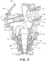
FIG. 2 depicts a partial cross-sectional view of the gearbox, in accordance with an aspect of an exemplary embodiment; and -
FIG. 3 depicts a detailed cross-sectional view of a portion of the gearbox ofFIG. 2 , in accordance with an aspect of an exemplary embodiment. - A vertical takeoff and landing (VTOL) or rotary wing aircraft, in accordance with an exemplary embodiment, is generally indicated at 10 in
FIGS 1 and2 . Rotarywing aircraft 10 including afuselage 12 supported by an airframe 14.Rotary wing aircraft 10 includes amain rotor system 16, which rotates about a main rotor axis R.Main rotor system 16 includes a plurality ofrotor blades 20 rotatable about a main rotor axis "R". Plurality ofrotor blades 20 is mounted to arotor hub 24 having arotor head 26.Main rotor system 16 is driven by agearbox 28 coupled to one or more prime movers, indicated generally at 30. -
Rotary wing aircraft 10 includes an extendingtail 40 that supports avertical stabilizer 42 and a horizontal stabilizer orstabilator 44. Atail rotor system 46 including a plurality of tail rotor blades, indicated generally at 48 is mounted tovertical stabilizer 42. In the embodiment shown,tail rotor system 46 provides yaw control forrotary wing aircraft 10.Rotary wing aircraft 10 includes forward supports or landing gear, one of which is indicated at 52, that may be connected to a retractable orfoldable support 53 arranged below a cabin portion (not separately labeled) offuselage 12 and a rear support orwheel 52 that may be connected to a rear retractable orfoldable support 55 supported at extendingtail 40. At this point, it should be understood, thatrotary wing aircraft 10 may take on various forms including dual rotor systems, pusher prop systems, and the like. -
Tail rotor system 46 may be operatively coupled togearbox 28 through a drive shaft (not shown) or through a system of drive shafts incorporating an intermediate gearbox (also not shown). More specifically, the drive shaft may extend fromgearbox 28 to atail gearbox 60. Referring toFIG. 2 ,tail gear box 60 includes ahousing 64 having aninterior 66.Housing 64 supports a first rotatingcomponent 70 that may take the form of an input shaft such as apinion gear 72.Housing 64 also supports a secondrotating component 74 that may take the form of anoutput shaft 74 that is coupled totail rotor system 46.Output shaft 74 is rotatably supported inhousing 64 through anoutput shaft bearing 75. -
Output shaft 74 includes a hollowinterior portion 78 that is receptive of apitch change shaft 82 oftail rotor system 46.Pitch change shaft 82 is supported within hollowinterior portion 78 through a pitchchange shaft bearing 85 and may be selectively manipulated to change a pitch angle oftail rotor blades 48. More specifically, apitch change member 90 is connected to pitchchange shaft 82 and selectively manipulated through a rotorcraft control system (not shown) to apply yaw control inputs torotorcraft 10 throughtail rotor system 46. -
Housing 64 includes aninput shaft casing 96 that supportspinion gear 72 through afirst bearing 98 and asecond bearing 100.Input shaft casing 96 defines alubricant sump 104 having alubricant reservoir 106 that promotes lubrication of first andsecond bearings submersible pump 110 is arranged inlubricant sump 104. In an exemplary embodiment,submersible pump 110 is disposed betweenfirst bearing 98 andsecond bearing 100. It should be understood that thesubmersible pump 110 may be arranged in other locations in thesump 104 and should not be considered as being limited the particular location shown, e.g., between twobearings submersible pump 110 operates to deliver a flow of lubricant onto pitch change bearing 85. Of course, it should be understood, thatsubmersible pump 110 may be configured to deliver a flow of lubricant onto other components either in conjunction with delivering lubricant to pitch change bearing 85 or as an alternative thereto.Submersible pump 110 is submerged inlubricant 112 within thesump 104. - Referring to
FIG. 3 and with continued reference toFIG. 2 ,submersible pump 110 includes afirst housing portion 114 that aligns with asecond housing portion 115 withininput shaft casing 96. First andsecond housing portions shaft casing 96. Animpeller 118 is disposed within first andsecond housing portions input shaft 72, which rotates relative to thehousing portions first housing portion 114 includes aninlet 128 andsecond housing portion 115 includes anoutlet 130. Amesh screen 134 is be disposed atinlet 128 in the shown embodiment.Mesh screen 134 is configured to prevent any particles that could be entrained in lubricant residing inlubricant reservoir 106 from entering intosubmersible pump 110. However, it is understood that themesh screen 134 need not be used in all aspects of the invention. - In accordance with an exemplary embodiment,
submersible pump 110 supports anozzle 140 that directs a flow of lubricant created by the rotation of theimpeller 118 towards pitch change bearing 85.Nozzle 140 includes afirst end 144 fluidically connected withhousing outlet 130 and asecond end 146 that is directed at pitch change bearing 85. As noted herein second oroutlet end 146 may be directed at other components. Further, it should be understood that multiple nozzles could be employed to guide lubricant onto multiple components. - At this point it should be appreciated that the exemplary embodiments describe a gearbox that is capable of directing lubricant onto one or more components regardless of aircraft orientation. The use of a pump and a nozzle(s) that are directed to particular components ensures that those components are provided with a selected amount of lubricant to enhance an overall operational life and reduce maintenance costs.
- While the present disclosure has been described in detail in connection with only a limited number of embodiments, it should be readily understood that the present disclosure is not limited to such disclosed embodiments. Rather, the present disclosure can be modified to incorporate any number of variations, alterations, substitutions or equivalent arrangements not heretofore described, but which are commensurate with the spirit and scope of the present disclosure. Additionally, while various embodiments of the present disclosure have been described, it is to be understood that aspects of the present disclosure may include only some of the described embodiments. Accordingly, the present disclosure is not to be seen as limited by the foregoing description, but is only limited by the scope of the appended claims.
Claims (15)
- A gearbox comprising:a casing having an interior;a rotating component arranged in the interior of the casing;a bearing including a rotating element, and a fixed element connected with the casing in the interior; anda submersible pump arranged in the interior of the casing, the submersible pump comprising:a first housing portion extending about the rotating component fixedly mounted to the casing at the interior;a second housing portion fixedly mounted to the casing at the interior and aligned with the first housing portion, the first and second housing portions forming a lubricant reservoir which holds lubricant; andan impeller mounted to the rotating component and arranged in the lubricant reservoir to pump lubricant according to a rotation of the rotating component, wherein one of the first and second housing portions includes an outlet through which the pumped lubricant is directed toward the rotating element.
- The gearbox according to claim 1, further comprising: a nozzle extending from the one of the first and second housing portions, the nozzle having a first end arranged at the outlet and fluidically exposed to the lubricant reservoir and a second end directed toward the bearing and through which the pumped lubricant is directed toward the rotating element of the bearing.
- The gearbox according to claim 1 or 2, further comprising: a lubricant sump arranged in the casing, the lubricant sump being fluidically connected with the lubricant reservoir.
- The gearbox according to claim 3, further comprising: a screen arranged between the lubricant sump and the lubricant reservoir.
- The gearbox according to one of claims 1-4, wherein the rotating component comprises a pinion.
- The gearbox according to one of claims 1-5, wherein the bearing comprises a tail rotor pitch change shaft bearing.
- A vehicle comprising:a body;a prime mover supported by the body;a rotating system mounted to the body; anda gearbox according to one of the preceding claims mechanically connected between the prime mover and the rotating system.
- The vehicle according to claim 7, further comprising: a nozzle extending from the one of the first and second housing portions, the nozzle having a first end arranged at the outlet and fluidically exposed to the lubricant reservoir and a second end directed toward the bearing and through which the pumped lubricant is directed toward the rotating element of the bearing.
- The vehicle according to claim 7 or 8, further comprising: a lubricant sump arranged in the casing, the lubricant sump being fluidically connected with the lubricant reservoir.
- The vehicle according to claim 9, further comprising: a screen arranged between the lubricant sump and the lubricant reservoir.
- The vehicle according to one of claims 7-10, wherein the rotating component comprises a pinion.
- The vehicle according to claim 11, wherein the pinion is rotatably supported in the casing through a first bearing and a second bearing, the submersible pump being arranged between the first bearing and the second bearing.
- The vehicle according to one of claims 7 to 12, wherein the bearing comprises a tail rotor pitch change shaft bearing.
- The vehicle according to one of claims 7-13, wherein the body comprises a fuselage of a rotorcraft.
- The vehicle according to one of claims 7-14, wherein the gearbox comprises a tail rotor gear box.
Applications Claiming Priority (1)
| Application Number | Priority Date | Filing Date | Title |
|---|---|---|---|
| US16/179,011 US11486487B2 (en) | 2018-11-02 | 2018-11-02 | Gearbox with integrated submersible lubricant pump |
Publications (2)
| Publication Number | Publication Date |
|---|---|
| EP3647630A1 true EP3647630A1 (en) | 2020-05-06 |
| EP3647630B1 EP3647630B1 (en) | 2025-10-22 |
Family
ID=68344732
Family Applications (1)
| Application Number | Title | Priority Date | Filing Date |
|---|---|---|---|
| EP19205355.1A Active EP3647630B1 (en) | 2018-11-02 | 2019-10-25 | Rotorcraft |
Country Status (2)
| Country | Link |
|---|---|
| US (1) | US11486487B2 (en) |
| EP (1) | EP3647630B1 (en) |
Families Citing this family (2)
| Publication number | Priority date | Publication date | Assignee | Title |
|---|---|---|---|---|
| DE102020109057A1 (en) * | 2020-04-01 | 2021-10-07 | Wittenstein Se | Adapter plate and gear with adapter plate |
| US12416354B2 (en) | 2022-11-08 | 2025-09-16 | Lockheed Martin Corporation | Lubrication system |
Citations (4)
| Publication number | Priority date | Publication date | Assignee | Title |
|---|---|---|---|---|
| US1920326A (en) * | 1930-01-30 | 1933-08-01 | Westinghouse Electric & Mfg Co | Vertical oil bearing |
| GB953485A (en) * | 1962-05-04 | 1964-03-25 | Ass Elect Ind | Improvements in vertically arranged machines with oil-lubricated bearings |
| US3786901A (en) * | 1971-06-03 | 1974-01-22 | Weir Pumps Ltd | Sealed lubricating system module |
| US4700808A (en) * | 1986-07-17 | 1987-10-20 | Haentjens Walter D | Shaft mounted bearing lubricating device |
Family Cites Families (15)
| Publication number | Priority date | Publication date | Assignee | Title |
|---|---|---|---|---|
| US3075690A (en) * | 1960-04-18 | 1963-01-29 | Emerson Electric Mfg Co | Enclosed transmission mechanism |
| JPS5853240B2 (en) * | 1979-07-16 | 1983-11-28 | 株式会社東芝 | Bearing oil supply device |
| US4429587A (en) * | 1981-09-10 | 1984-02-07 | General Electric Company | Attitude insensitive lubrication systems |
| DE3209514C2 (en) * | 1982-03-16 | 1984-04-26 | BHS-Bayerische Berg-, Hütten- und Salzwerke AG, 8000 München | Self-contained gear system with pressure lubrication |
| US4683985A (en) * | 1985-01-04 | 1987-08-04 | Dresser Industries, Inc. | Lubrication system for a vertical gear unit |
| US5411116A (en) | 1994-06-22 | 1995-05-02 | United Technologies Corporation | Self-scavenging, hybrid lubrication subsystem |
| FR2798983B1 (en) * | 1999-09-10 | 2001-11-23 | Eurocopter France | LUBRICATION DEVICE OF A MULTIPLIER-REDUCER MECHANICAL ASSEMBLY |
| GB2488142B (en) | 2011-02-17 | 2017-11-01 | Agustawestland Ltd | Tail rotor gearbox lubrication |
| US8905193B2 (en) * | 2012-07-25 | 2014-12-09 | Bell Helicopter Textron Inc. | Direct drive rotation device for passively moving fluid |
| US8997937B2 (en) * | 2012-07-25 | 2015-04-07 | Bell Helicopter Textron Inc. | Direct drive rotation device for passively moving fluid |
| US9470303B2 (en) | 2013-10-08 | 2016-10-18 | Sikorsky Aircraft Corporation | Self scavenging gear shield |
| EP3216696B1 (en) * | 2014-08-08 | 2018-04-11 | LEONARDO S.p.A. | Helicopter |
| US9765875B2 (en) * | 2015-06-19 | 2017-09-19 | Sikorsky Aircraft Corporation | Lubrication systems for gearbox assemblies |
| US20170138461A1 (en) | 2015-08-12 | 2017-05-18 | Sikorsky Aircraft Corporation | Lubrication systems |
| US10655728B2 (en) | 2015-12-01 | 2020-05-19 | The Boeing Company | Reconfigurable lubrication system for tiltrotor transmission |
-
2018
- 2018-11-02 US US16/179,011 patent/US11486487B2/en active Active
-
2019
- 2019-10-25 EP EP19205355.1A patent/EP3647630B1/en active Active
Patent Citations (4)
| Publication number | Priority date | Publication date | Assignee | Title |
|---|---|---|---|---|
| US1920326A (en) * | 1930-01-30 | 1933-08-01 | Westinghouse Electric & Mfg Co | Vertical oil bearing |
| GB953485A (en) * | 1962-05-04 | 1964-03-25 | Ass Elect Ind | Improvements in vertically arranged machines with oil-lubricated bearings |
| US3786901A (en) * | 1971-06-03 | 1974-01-22 | Weir Pumps Ltd | Sealed lubricating system module |
| US4700808A (en) * | 1986-07-17 | 1987-10-20 | Haentjens Walter D | Shaft mounted bearing lubricating device |
Also Published As
| Publication number | Publication date |
|---|---|
| EP3647630B1 (en) | 2025-10-22 |
| US20200141482A1 (en) | 2020-05-07 |
| US11486487B2 (en) | 2022-11-01 |
Similar Documents
| Publication | Publication Date | Title |
|---|---|---|
| US11565803B2 (en) | Electric drive system line replaceable unit with integrated cyclic actuation | |
| EP3066007B1 (en) | Counter-rotating rotor system with stationary standpipe | |
| US10697586B2 (en) | Supplemental lubrication pressurized by component or reservoir rotation | |
| EP3876400B1 (en) | Electric drive system line replaceable unit with integrated thermal cooling | |
| EP2505878B1 (en) | Gearbox with passive lubrication system | |
| EP3875374B1 (en) | Rotor system with an electric drive system line replaceable unit with integrated collective actuation | |
| US20170158323A1 (en) | Tiltrotor with Inboard Engines | |
| US12163584B2 (en) | Hybrid pressurized and non-pressurized lubrication system for aircraft gearbox | |
| US11530033B2 (en) | Thrust producing unit with a fail-safe electrical drive unit | |
| EP3055516B1 (en) | Self scavenging gear shield | |
| EP1739012B1 (en) | Helicopter with an auxiliary lubricating circuit | |
| EP2778062A1 (en) | Gimbaled tail rotor hub with spherical elastomeric centrifugal force bearing for blade retention and pitch change articulation | |
| US10752343B2 (en) | Electric propulsion system for a rotary wing aircraft | |
| EP3038904B1 (en) | Propeller gearbox oil cooler for a rotary wing aircraft | |
| US9090343B2 (en) | Rotor blade component cooling | |
| US11486487B2 (en) | Gearbox with integrated submersible lubricant pump | |
| US20170190415A1 (en) | Transmission for coaxial multi-rotor system | |
| US20200109777A1 (en) | Aircraft gearbox lubrication system with multiple lubrication subsystems | |
| US10112708B2 (en) | Weight efficient servo attachment scheme for rigid coaxial rotor control system | |
| EP2873613B1 (en) | Counter-rotating rotor system with static mast | |
| EP2703288B1 (en) | Electromechanical linear actuator for in blade rotor control | |
| EP3031720B1 (en) | Guide vanes for a pusher propeller for rotary wing aircraft | |
| US10473111B2 (en) | Variable pitch fan for a gas turbine engine | |
| EP3072814B1 (en) | Rotorcraft tail rotor blade assembly and method of forming the same | |
| US1986229A (en) | Controllable pitch propeller |
Legal Events
| Date | Code | Title | Description |
|---|---|---|---|
| PUAI | Public reference made under article 153(3) epc to a published international application that has entered the european phase |
Free format text: ORIGINAL CODE: 0009012 |
|
| STAA | Information on the status of an ep patent application or granted ep patent |
Free format text: STATUS: THE APPLICATION HAS BEEN PUBLISHED |
|
| AK | Designated contracting states |
Kind code of ref document: A1 Designated state(s): AL AT BE BG CH CY CZ DE DK EE ES FI FR GB GR HR HU IE IS IT LI LT LU LV MC MK MT NL NO PL PT RO RS SE SI SK SM TR |
|
| AX | Request for extension of the european patent |
Extension state: BA ME |
|
| STAA | Information on the status of an ep patent application or granted ep patent |
Free format text: STATUS: REQUEST FOR EXAMINATION WAS MADE |
|
| 17P | Request for examination filed |
Effective date: 20201008 |
|
| RBV | Designated contracting states (corrected) |
Designated state(s): AL AT BE BG CH CY CZ DE DK EE ES FI FR GB GR HR HU IE IS IT LI LT LU LV MC MK MT NL NO PL PT RO RS SE SI SK SM TR |
|
| STAA | Information on the status of an ep patent application or granted ep patent |
Free format text: STATUS: EXAMINATION IS IN PROGRESS |
|
| 17Q | First examination report despatched |
Effective date: 20210217 |
|
| P01 | Opt-out of the competence of the unified patent court (upc) registered |
Effective date: 20230523 |
|
| RIC1 | Information provided on ipc code assigned before grant |
Ipc: B64C 27/14 20060101ALN20250505BHEP Ipc: F16H 57/021 20120101ALN20250505BHEP Ipc: F16N 7/36 20060101ALI20250505BHEP Ipc: F16H 57/04 20100101ALI20250505BHEP Ipc: F16H 57/038 20120101AFI20250505BHEP |
|
| GRAP | Despatch of communication of intention to grant a patent |
Free format text: ORIGINAL CODE: EPIDOSNIGR1 |
|
| STAA | Information on the status of an ep patent application or granted ep patent |
Free format text: STATUS: GRANT OF PATENT IS INTENDED |
|
| INTG | Intention to grant announced |
Effective date: 20250617 |
|
| GRAS | Grant fee paid |
Free format text: ORIGINAL CODE: EPIDOSNIGR3 |
|
| GRAA | (expected) grant |
Free format text: ORIGINAL CODE: 0009210 |
|
| STAA | Information on the status of an ep patent application or granted ep patent |
Free format text: STATUS: THE PATENT HAS BEEN GRANTED |
|
| AK | Designated contracting states |
Kind code of ref document: B1 Designated state(s): AL AT BE BG CH CY CZ DE DK EE ES FI FR GB GR HR HU IE IS IT LI LT LU LV MC MK MT NL NO PL PT RO RS SE SI SK SM TR |
|
| REG | Reference to a national code |
Ref country code: CH Ref legal event code: F10 Free format text: ST27 STATUS EVENT CODE: U-0-0-F10-F00 (AS PROVIDED BY THE NATIONAL OFFICE) Effective date: 20251022 Ref country code: GB Ref legal event code: FG4D |
|
| REG | Reference to a national code |
Ref country code: DE Ref legal event code: R096 Ref document number: 602019077094 Country of ref document: DE |
|
| REG | Reference to a national code |
Ref country code: IE Ref legal event code: FG4D |
|
| PGFP | Annual fee paid to national office [announced via postgrant information from national office to epo] |
Ref country code: GB Payment date: 20251229 Year of fee payment: 7 |
|
| PGFP | Annual fee paid to national office [announced via postgrant information from national office to epo] |
Ref country code: IT Payment date: 20251219 Year of fee payment: 7 |
|
| PGFP | Annual fee paid to national office [announced via postgrant information from national office to epo] |
Ref country code: FR Payment date: 20251226 Year of fee payment: 7 |
|
| REG | Reference to a national code |
Ref country code: NL Ref legal event code: MP Effective date: 20251022 |
|
| PG25 | Lapsed in a contracting state [announced via postgrant information from national office to epo] |
Ref country code: NL Free format text: LAPSE BECAUSE OF FAILURE TO SUBMIT A TRANSLATION OF THE DESCRIPTION OR TO PAY THE FEE WITHIN THE PRESCRIBED TIME-LIMIT Effective date: 20251022 |
|
| PG25 | Lapsed in a contracting state [announced via postgrant information from national office to epo] |
Ref country code: ES Free format text: LAPSE BECAUSE OF FAILURE TO SUBMIT A TRANSLATION OF THE DESCRIPTION OR TO PAY THE FEE WITHIN THE PRESCRIBED TIME-LIMIT Effective date: 20251022 |
|
| REG | Reference to a national code |
Ref country code: LT Ref legal event code: MG9D |
|
| PG25 | Lapsed in a contracting state [announced via postgrant information from national office to epo] |
Ref country code: NO Free format text: LAPSE BECAUSE OF FAILURE TO SUBMIT A TRANSLATION OF THE DESCRIPTION OR TO PAY THE FEE WITHIN THE PRESCRIBED TIME-LIMIT Effective date: 20260122 |
|
| PGFP | Annual fee paid to national office [announced via postgrant information from national office to epo] |
Ref country code: DE Payment date: 20251229 Year of fee payment: 7 |
|
| PG25 | Lapsed in a contracting state [announced via postgrant information from national office to epo] |
Ref country code: FI Free format text: LAPSE BECAUSE OF FAILURE TO SUBMIT A TRANSLATION OF THE DESCRIPTION OR TO PAY THE FEE WITHIN THE PRESCRIBED TIME-LIMIT Effective date: 20251022 Ref country code: HR Free format text: LAPSE BECAUSE OF FAILURE TO SUBMIT A TRANSLATION OF THE DESCRIPTION OR TO PAY THE FEE WITHIN THE PRESCRIBED TIME-LIMIT Effective date: 20251022 Ref country code: AT Free format text: LAPSE BECAUSE OF FAILURE TO SUBMIT A TRANSLATION OF THE DESCRIPTION OR TO PAY THE FEE WITHIN THE PRESCRIBED TIME-LIMIT Effective date: 20251022 |
|
| REG | Reference to a national code |
Ref country code: AT Ref legal event code: MK05 Ref document number: 1849379 Country of ref document: AT Kind code of ref document: T Effective date: 20251022 |
|
| PG25 | Lapsed in a contracting state [announced via postgrant information from national office to epo] |
Ref country code: RS Free format text: LAPSE BECAUSE OF FAILURE TO SUBMIT A TRANSLATION OF THE DESCRIPTION OR TO PAY THE FEE WITHIN THE PRESCRIBED TIME-LIMIT Effective date: 20260122 |
|
| PG25 | Lapsed in a contracting state [announced via postgrant information from national office to epo] |
Ref country code: IS Free format text: LAPSE BECAUSE OF FAILURE TO SUBMIT A TRANSLATION OF THE DESCRIPTION OR TO PAY THE FEE WITHIN THE PRESCRIBED TIME-LIMIT Effective date: 20260222 |
|
| PG25 | Lapsed in a contracting state [announced via postgrant information from national office to epo] |
Ref country code: PT Free format text: LAPSE BECAUSE OF FAILURE TO SUBMIT A TRANSLATION OF THE DESCRIPTION OR TO PAY THE FEE WITHIN THE PRESCRIBED TIME-LIMIT Effective date: 20260223 |
|
| PG25 | Lapsed in a contracting state [announced via postgrant information from national office to epo] |
Ref country code: PL Free format text: LAPSE BECAUSE OF FAILURE TO SUBMIT A TRANSLATION OF THE DESCRIPTION OR TO PAY THE FEE WITHIN THE PRESCRIBED TIME-LIMIT Effective date: 20251022 |
|
| PG25 | Lapsed in a contracting state [announced via postgrant information from national office to epo] |
Ref country code: LV Free format text: LAPSE BECAUSE OF FAILURE TO SUBMIT A TRANSLATION OF THE DESCRIPTION OR TO PAY THE FEE WITHIN THE PRESCRIBED TIME-LIMIT Effective date: 20251022 |
|
| PG25 | Lapsed in a contracting state [announced via postgrant information from national office to epo] |
Ref country code: BG Free format text: LAPSE BECAUSE OF FAILURE TO SUBMIT A TRANSLATION OF THE DESCRIPTION OR TO PAY THE FEE WITHIN THE PRESCRIBED TIME-LIMIT Effective date: 20251022 |