EP3647629A1 - Gearbox ratio change - Google Patents
Gearbox ratio change Download PDFInfo
- Publication number
- EP3647629A1 EP3647629A1 EP19205114.2A EP19205114A EP3647629A1 EP 3647629 A1 EP3647629 A1 EP 3647629A1 EP 19205114 A EP19205114 A EP 19205114A EP 3647629 A1 EP3647629 A1 EP 3647629A1
- Authority
- EP
- European Patent Office
- Prior art keywords
- gear
- fuel pump
- teeth
- gearbox
- idler gear
- Prior art date
- Legal status (The legal status is an assumption and is not a legal conclusion. Google has not performed a legal analysis and makes no representation as to the accuracy of the status listed.)
- Withdrawn
Links
- 239000000446 fuel Substances 0.000 claims abstract description 50
- 238000000034 method Methods 0.000 claims abstract description 18
- 230000000153 supplemental effect Effects 0.000 claims description 7
- 230000001419 dependent effect Effects 0.000 claims description 2
- 230000009286 beneficial effect Effects 0.000 description 1
- 150000001875 compounds Chemical class 0.000 description 1
- 238000012986 modification Methods 0.000 description 1
- 230000004048 modification Effects 0.000 description 1
Images


Classifications
-
- F—MECHANICAL ENGINEERING; LIGHTING; HEATING; WEAPONS; BLASTING
- F01—MACHINES OR ENGINES IN GENERAL; ENGINE PLANTS IN GENERAL; STEAM ENGINES
- F01D—NON-POSITIVE DISPLACEMENT MACHINES OR ENGINES, e.g. STEAM TURBINES
- F01D15/00—Adaptations of machines or engines for special use; Combinations of engines with devices driven thereby
- F01D15/08—Adaptations for driving, or combinations with, pumps
-
- F—MECHANICAL ENGINEERING; LIGHTING; HEATING; WEAPONS; BLASTING
- F02—COMBUSTION ENGINES; HOT-GAS OR COMBUSTION-PRODUCT ENGINE PLANTS
- F02C—GAS-TURBINE PLANTS; AIR INTAKES FOR JET-PROPULSION PLANTS; CONTROLLING FUEL SUPPLY IN AIR-BREATHING JET-PROPULSION PLANTS
- F02C7/00—Features, components parts, details or accessories, not provided for in, or of interest apart form groups F02C1/00 - F02C6/00; Air intakes for jet-propulsion plants
- F02C7/32—Arrangement, mounting, or driving, of auxiliaries
-
- F—MECHANICAL ENGINEERING; LIGHTING; HEATING; WEAPONS; BLASTING
- F01—MACHINES OR ENGINES IN GENERAL; ENGINE PLANTS IN GENERAL; STEAM ENGINES
- F01D—NON-POSITIVE DISPLACEMENT MACHINES OR ENGINES, e.g. STEAM TURBINES
- F01D15/00—Adaptations of machines or engines for special use; Combinations of engines with devices driven thereby
- F01D15/10—Adaptations for driving, or combinations with, electric generators
-
- F—MECHANICAL ENGINEERING; LIGHTING; HEATING; WEAPONS; BLASTING
- F01—MACHINES OR ENGINES IN GENERAL; ENGINE PLANTS IN GENERAL; STEAM ENGINES
- F01D—NON-POSITIVE DISPLACEMENT MACHINES OR ENGINES, e.g. STEAM TURBINES
- F01D15/00—Adaptations of machines or engines for special use; Combinations of engines with devices driven thereby
- F01D15/12—Combinations with mechanical gearing
-
- F—MECHANICAL ENGINEERING; LIGHTING; HEATING; WEAPONS; BLASTING
- F16—ENGINEERING ELEMENTS AND UNITS; GENERAL MEASURES FOR PRODUCING AND MAINTAINING EFFECTIVE FUNCTIONING OF MACHINES OR INSTALLATIONS; THERMAL INSULATION IN GENERAL
- F16H—GEARING
- F16H1/00—Toothed gearings for conveying rotary motion
- F16H1/02—Toothed gearings for conveying rotary motion without gears having orbital motion
- F16H1/20—Toothed gearings for conveying rotary motion without gears having orbital motion involving more than two intermeshing members
- F16H1/206—Toothed gearings for conveying rotary motion without gears having orbital motion involving more than two intermeshing members characterised by the driving or driven member being composed of two or more gear wheels
-
- F—MECHANICAL ENGINEERING; LIGHTING; HEATING; WEAPONS; BLASTING
- F16—ENGINEERING ELEMENTS AND UNITS; GENERAL MEASURES FOR PRODUCING AND MAINTAINING EFFECTIVE FUNCTIONING OF MACHINES OR INSTALLATIONS; THERMAL INSULATION IN GENERAL
- F16H—GEARING
- F16H37/00—Combinations of mechanical gearings, not provided for in groups F16H1/00 - F16H35/00
- F16H37/02—Combinations of mechanical gearings, not provided for in groups F16H1/00 - F16H35/00 comprising essentially only toothed or friction gearings
- F16H37/04—Combinations of toothed gearings only
-
- F—MECHANICAL ENGINEERING; LIGHTING; HEATING; WEAPONS; BLASTING
- F16—ENGINEERING ELEMENTS AND UNITS; GENERAL MEASURES FOR PRODUCING AND MAINTAINING EFFECTIVE FUNCTIONING OF MACHINES OR INSTALLATIONS; THERMAL INSULATION IN GENERAL
- F16H—GEARING
- F16H57/00—General details of gearing
- F16H57/02—Gearboxes; Mounting gearing therein
-
- F—MECHANICAL ENGINEERING; LIGHTING; HEATING; WEAPONS; BLASTING
- F16—ENGINEERING ELEMENTS AND UNITS; GENERAL MEASURES FOR PRODUCING AND MAINTAINING EFFECTIVE FUNCTIONING OF MACHINES OR INSTALLATIONS; THERMAL INSULATION IN GENERAL
- F16H—GEARING
- F16H57/00—General details of gearing
- F16H57/02—Gearboxes; Mounting gearing therein
- F16H57/023—Mounting or installation of gears or shafts in the gearboxes, e.g. methods or means for assembly
-
- F—MECHANICAL ENGINEERING; LIGHTING; HEATING; WEAPONS; BLASTING
- F16—ENGINEERING ELEMENTS AND UNITS; GENERAL MEASURES FOR PRODUCING AND MAINTAINING EFFECTIVE FUNCTIONING OF MACHINES OR INSTALLATIONS; THERMAL INSULATION IN GENERAL
- F16H—GEARING
- F16H61/00—Control functions within control units of change-speed- or reversing-gearings for conveying rotary motion ; Control of exclusively fluid gearing, friction gearing, gearings with endless flexible members or other particular types of gearing
- F16H61/22—Locking of the control input devices
-
- F—MECHANICAL ENGINEERING; LIGHTING; HEATING; WEAPONS; BLASTING
- F05—INDEXING SCHEMES RELATING TO ENGINES OR PUMPS IN VARIOUS SUBCLASSES OF CLASSES F01-F04
- F05D—INDEXING SCHEME FOR ASPECTS RELATING TO NON-POSITIVE-DISPLACEMENT MACHINES OR ENGINES, GAS-TURBINES OR JET-PROPULSION PLANTS
- F05D2230/00—Manufacture
- F05D2230/80—Repairing, retrofitting or upgrading methods
-
- F—MECHANICAL ENGINEERING; LIGHTING; HEATING; WEAPONS; BLASTING
- F05—INDEXING SCHEMES RELATING TO ENGINES OR PUMPS IN VARIOUS SUBCLASSES OF CLASSES F01-F04
- F05D—INDEXING SCHEME FOR ASPECTS RELATING TO NON-POSITIVE-DISPLACEMENT MACHINES OR ENGINES, GAS-TURBINES OR JET-PROPULSION PLANTS
- F05D2260/00—Function
- F05D2260/40—Transmission of power
- F05D2260/403—Transmission of power through the shape of the drive components
- F05D2260/4031—Transmission of power through the shape of the drive components as in toothed gearing
Definitions
- This application relates to a method for achieving a gear ratio change in an existing gearbox, and unique gearboxes formed by the method.
- Gearboxes are known and provide a variety of speed ratios between an input and an output. In gas turbine engines, there are gearboxes that take in a drive input and provide varying rates of speed to any number of accessory applications.
- a gearbox will include a plurality of gears for driving a plurality of pumps and a generator for supporting a gas turbine engine.
- a method of modifying an existing gearbox wherein the existing gearbox has an input shaft connected to drive a first idler gear.
- the first idler gear engages a fuel pump gear for driving a fuel pump at a first speed.
- the step includes replacing the first idler gear with a replacement first idler gear having a distinct number of teeth, and replacing the fuel pump gear with a replacement fuel pump gear having a distinct number of teeth such that a speed output to at the fuel pump is distinct from the first speed.
- a gearbox is also disclosed.
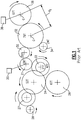
- FIG. 1 schematically shows a gearbox for use to support a number of pumps and generators in a gas turbine engine.
- a drive input 20 drives a gear 21 which engages a jackshaft 22.
- Gear 21 is a power takeoff shaft driven gear.
- Jackshaft gear 22 engages an idler gear 24 which, in turn, drives a gear 26 for driving a hydraulic pump.
- Jackshaft gear 22 is a compound idle gear, or an idler gear with two gears for a two-step gear reduction.
- Idler gear 24 further drives a jackshaft 27 and an ATS 28.
- the gear 21 further drives an idler gear 30, which engages in and drives an idler gear 32.
- Idler gear 32 drives a generator gear 34 for driving a generator and a fuel pump gear 36 for driving a fuel pump 38.
- gear 32 has 79 teeth and gear 36 has 67 teeth.
- gears are mounted within a gearbox housing, and a distance d 1 between center point C of gear 32 and gear 36 is set for mount pads within that housing.
- d 1 between center point C of gear 32 and gear 36 is set for mount pads within that housing.
- the number of gear teeth is proportional to the sides of the gears 32 and 36.
- the numbers of gear teeth are proportional to the sizes of the gears 32 and 36. More specifically, the number of teeth for a given gear is used with the diametral pitch of the gear to establish the pitch diameter of said gear. Diametral pitch is a term used to describe the relative size of a gear tooth. The pitch diameters are used to define the actual size of the tangent circles in the attached figures. The pitch diameters are always proportional to the numbers of teeth of their respective gears.
- the number of gear teeth on the several gears shown in Figure 1 results in a particular speed at the pump 38. Over time, it may be desirable to provide a pump 38 having a different speed. This is difficult to achieve without completely redesigning a gearbox, which may sometimes be undesirable.
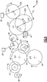
- FIG 2 shows a unique gearbox 99, and a method of achieving the unique gearbox 99, such that the speed of a fuel pump 38 changes.
- the gearbox 99 as illustrated in Figure 2 , the bulk of the gears remain the same as to Figure 1 .
- the idler gear 32 is replaced with an idler gear 132 and the pump drive gear 36 is replaced with the pump drive gear 136.
- the idler gear 132 now has 77 teeth, whereas the gear 32 has 79 teeth.
- the gear 136 now has 72 teeth whereas the gear 36 had 67 teeth. This now results in the speed at the pump 38 being reduced relative to the speed in the Figure 1 pump 38.
- a new, non-standard diametral pitch is used to define the gears 132 and 136.
- Gears that interact with gears 132 and 136 are changed to be adaptable with the non-standard diametral pitch value.
- gears 21, 22, 30, & 34 are designed to the new diametral pitch value, even though their numbers of teeth have not changed.
- the distance d 1 between the center C of the gears 132 and 136 remains the same distance d1 between gears in Figure 1 .
- the gears can sit on the same pads in the gearbox housing.
- the diametral pitch value of the gears in the first embodiment, Figure 2 is different, other secondary dimensions that are dependent on the size of the gear tooth will also change.
- the outside diameter, root diameter, and tooth thickness will likely change, even if by only a small amount.
- the face widths of the gears have a good chance of staying the same, but it may be necessary to adjust the face widths if updated stress analysis results dictate changes to them.
- FIG. 3 shows a gearbox 199 wherein the distinct speed at the fuel pump 38 is again achieved.
- the idler gear 232 is again changed to have 77 teeth, but the fuel pump gear 236 is changed to have 122 teeth.
- the distance between the centers C of the two gears remains at d 1 such that they can fit within the same gear mount pads.
- a second idler gear 200 is added to transmit rotation from the gear 234 to the gear 236.
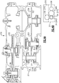
- Figure 4A shows the original gearbox 210, and the addition of a supplemental gearbox 211. It should be understood that Figure 4A (much like Figure 5 ) is somewhat inaccurate in that the gear 34 as shown in the gearbox 211 would actually be spaced into the paper relative to the gear 232.
- An extension 212 is shown in Figure 4A to represent the 24 toothed portion of the gear 34, which will engage and be driven with the idler gear 232. The 21 toothed gear portion of the gear 34 engages a second idler gear 200 to in turn drive the fuel pump drive gear 236.
- Figure 4B is an alternative view showing that the supplemental gearbox 211 is spaced in a plane perpendicular to the axis of rotation of the gears such that the gear 34 has its 24 toothed portion engaged and driven with the gear 232 (again at its 24 toothed portion) and a gear 34 engages and drives the gear 200.
- the actual centerlines of the gears may be closer, and there may in fact be overlap between the idler gears 200 and 232 as shown in Figure 3 .
- the supplemental gearbox is beneficial in that it provides mounting pads for the additional gear 200 to be added.
- Figure 5 shows a gearbox 299 that again achieves a distinct speed at the fuel pump 38.
- the gear 332 again has 77 teeth, but the gear 336 now has 95 teeth.
- the distance d 1 between the centers C of the gears 332 and 336 is the same distance d 1 .
- the idler gear 300 is provided with 24 teeth as is the gear 200.
- the gearbox 299 of Figure 5 may also be provided with a supplemental gearbox similar to the gearbox 211 shown in Figure 4B .
- the gears 32 and 36 are typically "standard” meaning a ratio of their diameter to the number of teeth on each of the engaged gears will be equal and in proportion to a standard pitch specification.
- the gears are non-standard meaning that, while the gears 132 and 136 still have ratios that are proportional to their respective pitch diameters, these diameters are derived using a non-standard pitch in order to enable the gears to operate at the same d 1 diameter, even though the numbers of teeth have changed.
- a method of modifying an existing gearbox could be said to include an existing gearbox having an input shaft connected to drive a first idler gear.
- the first idler gear engages a first fuel pump gear for driving a fuel pump at a first speed.
- the method includes a step of replacing the first idler gear with a replacement first idler gear having a distinct number of teeth, and replacing the first fuel pump gear with a replacement fuel pump gear having a distinct number of teeth such that a speed output to the fuel pump is distinct from the first speed.
- This disclosure provides unique gearboxes that achieve a distinct speed at a fuel pump and a method of modifying a speed ratio of one output gear in a gearbox.
Landscapes
- Engineering & Computer Science (AREA)
- General Engineering & Computer Science (AREA)
- Mechanical Engineering (AREA)
- Chemical & Material Sciences (AREA)
- Combustion & Propulsion (AREA)
- Gear Transmission (AREA)
Abstract
Description
- This application relates to a method for achieving a gear ratio change in an existing gearbox, and unique gearboxes formed by the method.
- Gearboxes are known and provide a variety of speed ratios between an input and an output. In gas turbine engines, there are gearboxes that take in a drive input and provide varying rates of speed to any number of accessory applications.
- As an example, a gearbox will include a plurality of gears for driving a plurality of pumps and a generator for supporting a gas turbine engine.
- A method of modifying an existing gearbox wherein the existing gearbox has an input shaft connected to drive a first idler gear. The first idler gear engages a fuel pump gear for driving a fuel pump at a first speed. There is a first distance between a center point of the first idler gear and the fuel pump gear. The step includes replacing the first idler gear with a replacement first idler gear having a distinct number of teeth, and replacing the fuel pump gear with a replacement fuel pump gear having a distinct number of teeth such that a speed output to at the fuel pump is distinct from the first speed.
- A gearbox is also disclosed.
- These and other features may be best understood from the following drawings and specification.
-
-
Figure 1 schematically shows an existing gearbox assembly for a gas turbine engine. -
Figure 2 shows a first modified gearbox. -
Figure 3 shows a second embodiment. -
Figure 4A shows a detail of the second embodiment. -
Figure 4B shows a second view. -
Figure 5 shows a third embodiment. -
Figure 1 schematically shows a gearbox for use to support a number of pumps and generators in a gas turbine engine. As shown, adrive input 20 drives agear 21 which engages ajackshaft 22. Gear 21 is a power takeoff shaft driven gear. Jackshaftgear 22 engages anidler gear 24 which, in turn, drives agear 26 for driving a hydraulic pump. Jackshaftgear 22 is a compound idle gear, or an idler gear with two gears for a two-step gear reduction. Idlergear 24 further drives ajackshaft 27 and an ATS 28. - The
gear 21 further drives anidler gear 30, which engages in and drives anidler gear 32. Idlergear 32 drives agenerator gear 34 for driving a generator and afuel pump gear 36 for driving afuel pump 38. In this prior art gearbox,gear 32 has 79 teeth andgear 36 has 67 teeth. - As can be appreciated, the gears are mounted within a gearbox housing, and a distance d1 between center point C of
gear 32 andgear 36 is set for mount pads within that housing. In the gearbox shown inFigure 1 , the number of gear teeth is proportional to the sides of thegears - In the gearbox shown in
Figure 1 , the numbers of gear teeth are proportional to the sizes of thegears - As can be appreciated, the number of gear teeth on the several gears shown in
Figure 1 results in a particular speed at thepump 38. Over time, it may be desirable to provide apump 38 having a different speed. This is difficult to achieve without completely redesigning a gearbox, which may sometimes be undesirable. -
Figure 2 shows aunique gearbox 99, and a method of achieving theunique gearbox 99, such that the speed of afuel pump 38 changes. In thegearbox 99, as illustrated inFigure 2 , the bulk of the gears remain the same as toFigure 1 . However, theidler gear 32 is replaced with anidler gear 132 and thepump drive gear 36 is replaced with thepump drive gear 136. Theidler gear 132 now has 77 teeth, whereas thegear 32 has 79 teeth. Thegear 136 now has 72 teeth whereas thegear 36 had 67 teeth. This now results in the speed at thepump 38 being reduced relative to the speed in theFigure 1 pump 38. - In addition, the tooth thickness on the
gears - In
Figure 2 , it can be seen that the numbers of teeth ingears gears Figure 1 . Because a central tenet of gear design suggests that the pitch circles of any given gear mesh should be tangent with each other, the diametral pitch of thegears - For the embodiment in
Figure 2 , a new, non-standard diametral pitch is used to define thegears gears gears - The distance d1 between the center C of the
gears Figure 1 . Thus, the gears can sit on the same pads in the gearbox housing. Because the diametral pitch value of the gears in the first embodiment,Figure 2 , is different, other secondary dimensions that are dependent on the size of the gear tooth will also change. As a result, the outside diameter, root diameter, and tooth thickness will likely change, even if by only a small amount. The face widths of the gears have a good chance of staying the same, but it may be necessary to adjust the face widths if updated stress analysis results dictate changes to them. -
Figure 3 shows agearbox 199 wherein the distinct speed at thefuel pump 38 is again achieved. In this gearbox, theidler gear 232 is again changed to have 77 teeth, but thefuel pump gear 236 is changed to have 122 teeth. The distance between the centers C of the two gears remains at d1 such that they can fit within the same gear mount pads. However, asecond idler gear 200 is added to transmit rotation from the gear 234 to thegear 236. -
Figure 4A shows theoriginal gearbox 210, and the addition of asupplemental gearbox 211. It should be understood thatFigure 4A (much likeFigure 5 ) is somewhat inaccurate in that thegear 34 as shown in thegearbox 211 would actually be spaced into the paper relative to thegear 232. Anextension 212 is shown inFigure 4A to represent the 24 toothed portion of thegear 34, which will engage and be driven with theidler gear 232. The 21 toothed gear portion of thegear 34 engages asecond idler gear 200 to in turn drive the fuelpump drive gear 236. -
Figure 4B is an alternative view showing that thesupplemental gearbox 211 is spaced in a plane perpendicular to the axis of rotation of the gears such that thegear 34 has its 24 toothed portion engaged and driven with the gear 232 (again at its 24 toothed portion) and agear 34 engages and drives thegear 200. As is clear fromFigure 3 , the actual centerlines of the gears may be closer, and there may in fact be overlap between the idler gears 200 and 232 as shown inFigure 3 . The supplemental gearbox is beneficial in that it provides mounting pads for theadditional gear 200 to be added. -
Figure 5 shows agearbox 299 that again achieves a distinct speed at thefuel pump 38. Thegear 332 again has 77 teeth, but thegear 336 now has 95 teeth. The distance d1 between the centers C of thegears idler gear 300 is provided with 24 teeth as is thegear 200. - The
gearbox 299 ofFigure 5 may also be provided with a supplemental gearbox similar to thegearbox 211 shown inFigure 4B . - In standard gear design the
gears gears - A method of modifying an existing gearbox could be said to include an existing gearbox having an input shaft connected to drive a first idler gear. The first idler gear engages a first fuel pump gear for driving a fuel pump at a first speed. There is a first distance between a center point of the first idler gear and the fuel pump gear. The method includes a step of replacing the first idler gear with a replacement first idler gear having a distinct number of teeth, and replacing the first fuel pump gear with a replacement fuel pump gear having a distinct number of teeth such that a speed output to the fuel pump is distinct from the first speed.
- This disclosure provides unique gearboxes that achieve a distinct speed at a fuel pump and a method of modifying a speed ratio of one output gear in a gearbox.
- Although an embodiment of this invention has been disclosed, a worker of ordinary skill in this art would recognize that certain modifications would come within the scope of the invention as defined by the claims. For that reason, the following claims should be studied to determine the true scope of the invention.
Claims (13)
- A method of modifying an existing gearbox comprising the steps of:(a) wherein the existing gearbox has an input shaft connected to drive a first idler gear (32), the first idler gear engages a first fuel pump gear (36) for driving a fuel pump (38) at a first speed, and there being a first distance between a center point of the first idler gear and the fuel pump gear; and(b) including the step of replacing said first idler gear with a replacement first idler gear (132) having a distinct number of teeth, and replacing said first fuel pump gear with a replacement fuel pump gear (136) having a distinct number of teeth such that a speed output to said fuel pump is distinct from the first speed.
- The method as set forth in claim 1, wherein the method further includes the step of inserting a second idler gear (200) rotating with said replacement fuel pump gear, and selectively engaging a drive gear for a generator and said second idler gear driving said replacement fuel pump gear.
- The method as set forth in claim 2, wherein said replacement first idler gear has 77 teeth.
- The method as set forth in claim 3, wherein said second idler gear has 24 teeth.
- The method as set forth in claim 2, 3 or 4, wherein said replacement fuel pump drive gear has 122 teeth.
- The method as set forth in claim 2, 3 or 4, wherein said replacement fuel pump drive gear has 95 teeth.
- The method as set forth in claim 1, 2, 3 or 4 wherein said replacement fuel pump gear has 72 teeth.
- The method as set forth in any preceding claim, wherein said replacement fuel pump gear and a gear driving said replacement fuel pump gear have diameters derived using a non-standard pitch.
- The method as set forth in claim 2 or any claim dependent thereon, wherein a supplemental gearbox (211) is mounted to an existing gearbox and houses a portion of said drive gear for said generator, said second idler gear, and said replacement fuel pump gear.
- A gearbox for driving a plurality of components associated with a gas turbine engine comprising;
a first idler gear (132) selectively engaged to be driven by an input, wherein said first idler gear drives a fuel pump drive gear (136) at a first speed, wherein a ratio of a diameter of said fuel pump drive gear to a number of teeth on said fuel pump drive gear is not equal to a ratio of a diameter of a gear driving said fuel pump drive gear to a number of teeth on said gear driving said fuel pump drive gear. - The gearbox as set forth in claim 10, wherein said first idler gear has 77 teeth and said fuel pump drive gear has 72 teeth.
- The gearbox as set forth in claim 10, wherein a second idler gear (200) is selectively driven and is said gear driving said fuel pump drive gear, said second idler gear has 24 teeth, and said fuel pump gear has 95 teeth or 122 teeth, said fuel pump gear has 122 teeth.
- The gearbox as set forth in claim 12, wherein said first idler gear is mounted in a first gearbox, and said first idler gear rotating on an axis, and there being a supplemental gearbox (211) spaced from said first gearbox along said axis of rotation, with said second idler gear (200) and said fuel pump drive gear being mounted in said supplemental gearbox.
Applications Claiming Priority (1)
| Application Number | Priority Date | Filing Date | Title |
|---|---|---|---|
| US16/169,839 US11168577B2 (en) | 2018-10-24 | 2018-10-24 | Gearbox ratio change |
Publications (1)
| Publication Number | Publication Date |
|---|---|
| EP3647629A1 true EP3647629A1 (en) | 2020-05-06 |
Family
ID=68342810
Family Applications (1)
| Application Number | Title | Priority Date | Filing Date |
|---|---|---|---|
| EP19205114.2A Withdrawn EP3647629A1 (en) | 2018-10-24 | 2019-10-24 | Gearbox ratio change |
Country Status (2)
| Country | Link |
|---|---|
| US (1) | US11168577B2 (en) |
| EP (1) | EP3647629A1 (en) |
Citations (4)
| Publication number | Priority date | Publication date | Assignee | Title |
|---|---|---|---|---|
| US20070173365A1 (en) * | 2005-10-21 | 2007-07-26 | Hispano Suiza | Device for driving accessory machines of a gas turbine engine |
| EP2060759A2 (en) * | 2007-11-14 | 2009-05-20 | United Technologies Corporation | Split gearbox and nacelle arrangement |
| US20120006137A1 (en) * | 2010-07-07 | 2012-01-12 | Hamilton Sundstrand Corporation | Gear driven accessory for gearbox |
| US20180283281A1 (en) * | 2017-03-31 | 2018-10-04 | Hamilton Sundstrand Corporation | Accessory gearboxes |
Family Cites Families (4)
| Publication number | Priority date | Publication date | Assignee | Title |
|---|---|---|---|---|
| US4976669A (en) | 1989-07-20 | 1990-12-11 | Williams International Corporation | Dual output planetary gear system |
| US9845735B2 (en) | 2015-01-14 | 2017-12-19 | United Technologies Corporation | System and apparatus for diversified gearbox |
| US20160230843A1 (en) | 2015-02-09 | 2016-08-11 | United Technologies Corporation | Gearbox for gas turbine engine |
| US10100673B2 (en) | 2015-09-04 | 2018-10-16 | Hamilton Sundstrand Corporation | Pump gear |
-
2018
- 2018-10-24 US US16/169,839 patent/US11168577B2/en not_active Expired - Fee Related
-
2019
- 2019-10-24 EP EP19205114.2A patent/EP3647629A1/en not_active Withdrawn
Patent Citations (4)
| Publication number | Priority date | Publication date | Assignee | Title |
|---|---|---|---|---|
| US20070173365A1 (en) * | 2005-10-21 | 2007-07-26 | Hispano Suiza | Device for driving accessory machines of a gas turbine engine |
| EP2060759A2 (en) * | 2007-11-14 | 2009-05-20 | United Technologies Corporation | Split gearbox and nacelle arrangement |
| US20120006137A1 (en) * | 2010-07-07 | 2012-01-12 | Hamilton Sundstrand Corporation | Gear driven accessory for gearbox |
| US20180283281A1 (en) * | 2017-03-31 | 2018-10-04 | Hamilton Sundstrand Corporation | Accessory gearboxes |
Also Published As
| Publication number | Publication date |
|---|---|
| US11168577B2 (en) | 2021-11-09 |
| US20200131924A1 (en) | 2020-04-30 |
Similar Documents
| Publication | Publication Date | Title |
|---|---|---|
| US3546972A (en) | Profile shifted involute internal gearing | |
| EP2530282B1 (en) | Dual drive of an accessory drive gearbox | |
| JP4366188B2 (en) | Gearbox series | |
| RU2702071C2 (en) | Compact transmission | |
| CA2738493C (en) | Speed changer assembly | |
| EP2405116A2 (en) | Accessory Gearbox Assembly | |
| EP3306116B1 (en) | Geared turbofan engine and sun shaft for driving sun gear of planetary gearbox | |
| US7971499B2 (en) | Adjustable gear position arrangement for synchronization of multiple generators | |
| US4513637A (en) | Gearing assembly | |
| US5376057A (en) | Multistage differential gear package | |
| US6348022B1 (en) | Planetary gear transmission apparatus | |
| US4811615A (en) | Mechanism for eliminating gear rattle in a shiftable transmission | |
| US11168577B2 (en) | Gearbox ratio change | |
| US7828687B2 (en) | Modular planetary gear assembly and drive | |
| US20060107787A1 (en) | Adjustable gear position arrangement for synchronization of multiple generators | |
| DE102014205936B4 (en) | Engine with a counterweight device arranged on a crankshaft | |
| EP3708874A1 (en) | Differential unit gear shrouds | |
| RU2606157C2 (en) | Drive with gearbox system | |
| DE4241550B4 (en) | Gear unit for handling equipment | |
| DK201970782A1 (en) | Wind turbine power transmission system | |
| DE3923370C2 (en) | ||
| WO2005121583A1 (en) | Offset drive direct ratio gear coupling | |
| CN101720398B (en) | Method for the production of a transmission and transmission line | |
| EP3708875A1 (en) | Hydraulic unit gear shrouds | |
| US20200332720A1 (en) | Transmission systems having clutch at output side |
Legal Events
| Date | Code | Title | Description |
|---|---|---|---|
| PUAI | Public reference made under article 153(3) epc to a published international application that has entered the european phase |
Free format text: ORIGINAL CODE: 0009012 |
|
| STAA | Information on the status of an ep patent application or granted ep patent |
Free format text: STATUS: THE APPLICATION HAS BEEN PUBLISHED |
|
| AK | Designated contracting states |
Kind code of ref document: A1 Designated state(s): AL AT BE BG CH CY CZ DE DK EE ES FI FR GB GR HR HU IE IS IT LI LT LU LV MC MK MT NL NO PL PT RO RS SE SI SK SM TR |
|
| AX | Request for extension of the european patent |
Extension state: BA ME |
|
| STAA | Information on the status of an ep patent application or granted ep patent |
Free format text: STATUS: REQUEST FOR EXAMINATION WAS MADE |
|
| 17P | Request for examination filed |
Effective date: 20201106 |
|
| RBV | Designated contracting states (corrected) |
Designated state(s): AL AT BE BG CH CY CZ DE DK EE ES FI FR GB GR HR HU IE IS IT LI LT LU LV MC MK MT NL NO PL PT RO RS SE SI SK SM TR |
|
| STAA | Information on the status of an ep patent application or granted ep patent |
Free format text: STATUS: EXAMINATION IS IN PROGRESS |
|
| 17Q | First examination report despatched |
Effective date: 20210729 |
|
| STAA | Information on the status of an ep patent application or granted ep patent |
Free format text: STATUS: THE APPLICATION IS DEEMED TO BE WITHDRAWN |
|
| 18D | Application deemed to be withdrawn |
Effective date: 20240822 |