EP3647592A1 - Motor-driven compressor - Google Patents
Motor-driven compressor Download PDFInfo
- Publication number
- EP3647592A1 EP3647592A1 EP19203505.3A EP19203505A EP3647592A1 EP 3647592 A1 EP3647592 A1 EP 3647592A1 EP 19203505 A EP19203505 A EP 19203505A EP 3647592 A1 EP3647592 A1 EP 3647592A1
- Authority
- EP
- European Patent Office
- Prior art keywords
- cover
- motor
- thickness
- housing
- insertion holes
- Prior art date
- Legal status (The legal status is an assumption and is not a legal conclusion. Google has not performed a legal analysis and makes no representation as to the accuracy of the status listed.)
- Granted
Links
Images



Classifications
-
- F—MECHANICAL ENGINEERING; LIGHTING; HEATING; WEAPONS; BLASTING
- F04—POSITIVE - DISPLACEMENT MACHINES FOR LIQUIDS; PUMPS FOR LIQUIDS OR ELASTIC FLUIDS
- F04C—ROTARY-PISTON, OR OSCILLATING-PISTON, POSITIVE-DISPLACEMENT MACHINES FOR LIQUIDS; ROTARY-PISTON, OR OSCILLATING-PISTON, POSITIVE-DISPLACEMENT PUMPS
- F04C18/00—Rotary-piston pumps specially adapted for elastic fluids
- F04C18/02—Rotary-piston pumps specially adapted for elastic fluids of arcuate-engagement type, i.e. with circular translatory movement of co-operating members, each member having the same number of teeth or tooth-equivalents
- F04C18/0207—Rotary-piston pumps specially adapted for elastic fluids of arcuate-engagement type, i.e. with circular translatory movement of co-operating members, each member having the same number of teeth or tooth-equivalents both members having co-operating elements in spiral form
- F04C18/0215—Rotary-piston pumps specially adapted for elastic fluids of arcuate-engagement type, i.e. with circular translatory movement of co-operating members, each member having the same number of teeth or tooth-equivalents both members having co-operating elements in spiral form where only one member is moving
-
- F—MECHANICAL ENGINEERING; LIGHTING; HEATING; WEAPONS; BLASTING
- F04—POSITIVE - DISPLACEMENT MACHINES FOR LIQUIDS; PUMPS FOR LIQUIDS OR ELASTIC FLUIDS
- F04C—ROTARY-PISTON, OR OSCILLATING-PISTON, POSITIVE-DISPLACEMENT MACHINES FOR LIQUIDS; ROTARY-PISTON, OR OSCILLATING-PISTON, POSITIVE-DISPLACEMENT PUMPS
- F04C29/00—Component parts, details or accessories of pumps or pumping installations, not provided for in groups F04C18/00 - F04C28/00
-
- F—MECHANICAL ENGINEERING; LIGHTING; HEATING; WEAPONS; BLASTING
- F04—POSITIVE - DISPLACEMENT MACHINES FOR LIQUIDS; PUMPS FOR LIQUIDS OR ELASTIC FLUIDS
- F04B—POSITIVE-DISPLACEMENT MACHINES FOR LIQUIDS; PUMPS
- F04B39/00—Component parts, details, or accessories, of pumps or pumping systems specially adapted for elastic fluids, not otherwise provided for in, or of interest apart from, groups F04B25/00 - F04B37/00
- F04B39/12—Casings; Cylinders; Cylinder heads; Fluid connections
- F04B39/121—Casings
-
- H—ELECTRICITY
- H02—GENERATION; CONVERSION OR DISTRIBUTION OF ELECTRIC POWER
- H02K—DYNAMO-ELECTRIC MACHINES
- H02K5/00—Casings; Enclosures; Supports
- H02K5/24—Casings; Enclosures; Supports specially adapted for suppression or reduction of noise or vibrations
-
- F—MECHANICAL ENGINEERING; LIGHTING; HEATING; WEAPONS; BLASTING
- F04—POSITIVE - DISPLACEMENT MACHINES FOR LIQUIDS; PUMPS FOR LIQUIDS OR ELASTIC FLUIDS
- F04C—ROTARY-PISTON, OR OSCILLATING-PISTON, POSITIVE-DISPLACEMENT MACHINES FOR LIQUIDS; ROTARY-PISTON, OR OSCILLATING-PISTON, POSITIVE-DISPLACEMENT PUMPS
- F04C23/00—Combinations of two or more pumps, each being of rotary-piston or oscillating-piston type, specially adapted for elastic fluids; Pumping installations specially adapted for elastic fluids; Multi-stage pumps specially adapted for elastic fluids
- F04C23/008—Hermetic pumps
-
- F—MECHANICAL ENGINEERING; LIGHTING; HEATING; WEAPONS; BLASTING
- F04—POSITIVE - DISPLACEMENT MACHINES FOR LIQUIDS; PUMPS FOR LIQUIDS OR ELASTIC FLUIDS
- F04C—ROTARY-PISTON, OR OSCILLATING-PISTON, POSITIVE-DISPLACEMENT MACHINES FOR LIQUIDS; ROTARY-PISTON, OR OSCILLATING-PISTON, POSITIVE-DISPLACEMENT PUMPS
- F04C23/00—Combinations of two or more pumps, each being of rotary-piston or oscillating-piston type, specially adapted for elastic fluids; Pumping installations specially adapted for elastic fluids; Multi-stage pumps specially adapted for elastic fluids
- F04C23/02—Pumps characterised by combination with, or adaptation to, specific driving engines or motors
-
- F—MECHANICAL ENGINEERING; LIGHTING; HEATING; WEAPONS; BLASTING
- F04—POSITIVE - DISPLACEMENT MACHINES FOR LIQUIDS; PUMPS FOR LIQUIDS OR ELASTIC FLUIDS
- F04C—ROTARY-PISTON, OR OSCILLATING-PISTON, POSITIVE-DISPLACEMENT MACHINES FOR LIQUIDS; ROTARY-PISTON, OR OSCILLATING-PISTON, POSITIVE-DISPLACEMENT PUMPS
- F04C29/00—Component parts, details or accessories of pumps or pumping installations, not provided for in groups F04C18/00 - F04C28/00
- F04C29/0042—Driving elements, brakes, couplings, transmissions specially adapted for pumps
- F04C29/0085—Prime movers
-
- F—MECHANICAL ENGINEERING; LIGHTING; HEATING; WEAPONS; BLASTING
- F04—POSITIVE - DISPLACEMENT MACHINES FOR LIQUIDS; PUMPS FOR LIQUIDS OR ELASTIC FLUIDS
- F04D—NON-POSITIVE-DISPLACEMENT PUMPS
- F04D25/00—Pumping installations or systems
- F04D25/02—Units comprising pumps and their driving means
- F04D25/06—Units comprising pumps and their driving means the pump being electrically driven
- F04D25/0606—Units comprising pumps and their driving means the pump being electrically driven the electric motor being specially adapted for integration in the pump
-
- H—ELECTRICITY
- H02—GENERATION; CONVERSION OR DISTRIBUTION OF ELECTRIC POWER
- H02K—DYNAMO-ELECTRIC MACHINES
- H02K11/00—Structural association of dynamo-electric machines with electric components or with devices for shielding, monitoring or protection
- H02K11/30—Structural association with control circuits or drive circuits
- H02K11/33—Drive circuits, e.g. power electronics
-
- F—MECHANICAL ENGINEERING; LIGHTING; HEATING; WEAPONS; BLASTING
- F04—POSITIVE - DISPLACEMENT MACHINES FOR LIQUIDS; PUMPS FOR LIQUIDS OR ELASTIC FLUIDS
- F04C—ROTARY-PISTON, OR OSCILLATING-PISTON, POSITIVE-DISPLACEMENT MACHINES FOR LIQUIDS; ROTARY-PISTON, OR OSCILLATING-PISTON, POSITIVE-DISPLACEMENT PUMPS
- F04C2210/00—Fluid
- F04C2210/26—Refrigerants with particular properties, e.g. HFC-134a
-
- F—MECHANICAL ENGINEERING; LIGHTING; HEATING; WEAPONS; BLASTING
- F04—POSITIVE - DISPLACEMENT MACHINES FOR LIQUIDS; PUMPS FOR LIQUIDS OR ELASTIC FLUIDS
- F04C—ROTARY-PISTON, OR OSCILLATING-PISTON, POSITIVE-DISPLACEMENT MACHINES FOR LIQUIDS; ROTARY-PISTON, OR OSCILLATING-PISTON, POSITIVE-DISPLACEMENT PUMPS
- F04C2240/00—Components
- F04C2240/30—Casings or housings
-
- F—MECHANICAL ENGINEERING; LIGHTING; HEATING; WEAPONS; BLASTING
- F04—POSITIVE - DISPLACEMENT MACHINES FOR LIQUIDS; PUMPS FOR LIQUIDS OR ELASTIC FLUIDS
- F04C—ROTARY-PISTON, OR OSCILLATING-PISTON, POSITIVE-DISPLACEMENT MACHINES FOR LIQUIDS; ROTARY-PISTON, OR OSCILLATING-PISTON, POSITIVE-DISPLACEMENT PUMPS
- F04C2240/00—Components
- F04C2240/40—Electric motor
- F04C2240/403—Electric motor with inverter for speed control
-
- F—MECHANICAL ENGINEERING; LIGHTING; HEATING; WEAPONS; BLASTING
- F04—POSITIVE - DISPLACEMENT MACHINES FOR LIQUIDS; PUMPS FOR LIQUIDS OR ELASTIC FLUIDS
- F04C—ROTARY-PISTON, OR OSCILLATING-PISTON, POSITIVE-DISPLACEMENT MACHINES FOR LIQUIDS; ROTARY-PISTON, OR OSCILLATING-PISTON, POSITIVE-DISPLACEMENT PUMPS
- F04C2240/00—Components
- F04C2240/80—Other components
- F04C2240/805—Fastening means, e.g. bolts
-
- F—MECHANICAL ENGINEERING; LIGHTING; HEATING; WEAPONS; BLASTING
- F04—POSITIVE - DISPLACEMENT MACHINES FOR LIQUIDS; PUMPS FOR LIQUIDS OR ELASTIC FLUIDS
- F04C—ROTARY-PISTON, OR OSCILLATING-PISTON, POSITIVE-DISPLACEMENT MACHINES FOR LIQUIDS; ROTARY-PISTON, OR OSCILLATING-PISTON, POSITIVE-DISPLACEMENT PUMPS
- F04C2240/00—Components
- F04C2240/80—Other components
- F04C2240/808—Electronic circuits (e.g. inverters) installed inside the machine
-
- F—MECHANICAL ENGINEERING; LIGHTING; HEATING; WEAPONS; BLASTING
- F05—INDEXING SCHEMES RELATING TO ENGINES OR PUMPS IN VARIOUS SUBCLASSES OF CLASSES F01-F04
- F05B—INDEXING SCHEME RELATING TO WIND, SPRING, WEIGHT, INERTIA OR LIKE MOTORS, TO MACHINES OR ENGINES FOR LIQUIDS COVERED BY SUBCLASSES F03B, F03D AND F03G
- F05B2210/00—Working fluid
- F05B2210/10—Kind or type
- F05B2210/14—Refrigerants with particular properties, e.g. HFC-134a
Definitions
- the following description relates to a motor-driven compressor.
- Japanese Laid-Open Patent Publication No. 2013-177826 discloses a motor-driven compressor.
- the motor-driven compressor includes a compression mechanism, an electric motor, an inverter, a housing, and a cover.
- the compression mechanism compresses refrigerant.
- the electric motor drives the compression mechanism.
- the inverter controls the driving of the electric motor.
- the housing accommodates the compression mechanism and the electric motor.
- the cover is fastened to the housing by fasteners to define an accommodation chamber with the housing to accommodate the inverter.
- the cover is made of aluminum alloy and includes a plate-shaped body wall.
- the body wall includes a first surface opposed to the inverter in the accommodation chamber and a second surface located on the side opposite from the first surface.
- the body wall includes insertion holes extending through the periphery of the body wall. Each fastener is inserted through the corresponding insertion hole.
- the body wall includes ribs protruding from the first surface toward the inverter.
- the ribs protrude from the first surface toward the inverter. This reduces the size of the accommodation chamber. As a result, the inverter and the ribs easily interfere with each other in the accommodation chamber. If the accommodation chamber is increased in size in order to solve this problem, the cover is enlarged in the axial direction. This enlarges the motor-driven compressor and increases the weight of the motor-driven compressor.
- the ribs may be protruded from the second surface. Nevertheless, the second surface is located outside the motor-driven compressor. This facilitates deposition of foreign matter such as dust or salt in the ribs protruding from the second surface. Thus, the cover easily corrodes, thereby decreasing the durability.
- the protrusion of the ribs from the second surface enlarges the cover and consequently enlarges the motor-driven compressor in the axial direction.
- a motor-driven compressor includes a compression mechanism configured to compress fluid, an electric motor configured to drive the compression mechanism, an inverter configured to control driving of the electric motor, a housing that accommodates the compression mechanism and the electric motor, and a cover fastened to the housing by fasteners, the cover defining an accommodation chamber with the housing to accommodate the inverter.
- the cover includes a plate-shaped body wall and insertion holes extending through a periphery of the body wall, the fasteners being inserted through the insertion holes.
- the body wall includes a first surface opposed to the inverter in the accommodation chamber, a second surface located at a side opposite from the first surface, a first thickness portion having a first thickness, and a second thickness portion located around at least one of the insertion holes.
- the second thickness portion has a second thickness that is smaller than the first thickness and is obtained by recessing the body wall from the first surface toward the second surface.
- Exemplary embodiments may have different forms, and are not limited to the examples described. However, the examples described are thorough and complete, and convey the full scope of the disclosure to one of ordinary skill in the art.
- This compressor is installed in a vehicle and configures a refrigeration circuit of a vehicle air conditioner.
- the motor-driven compressor of the present embodiment includes a housing 1, a motor-driven compressor 3, a compression mechanism 5, a cover 7, an inverter 9, and a positioner 31.
- the housing 1 includes a first housing member 11 and a second housing member 13.
- the upper, lower, left, and right directions of the motor-driven compressor are defined using coordinate axes shown in Fig. 1 .
- the upper, lower, left, and right directions are defined using coordinate axes corresponding to Fig. 1 .
- the front-rear direction of the motor-driven compressor is defined such that the side where the second housing member 13 is located relative to the first housing member 11 is set as the front and the side where the cover 7 is located relative to the first housing member 11 is set as the rear.
- the first housing member 11 is made of aluminum alloy.
- the first housing member 11 includes a first end wall 11a (first bottom wall), a first circumferential wall 11b (first side wall), and a first flange 11c.
- the first end wall 11a is the rear end of the first housing member 11 and extends in the radial direction of the motor-driven compressor.
- the first circumferential wall 11b is continuous with the first end wall 11a and extends frontward from the first end wall 11a along the axis of the motor-driven compressor.
- the first end wall 11a is an end wall that closes the rear end of the first circumferential wall 11b, and the front end of the first circumferential wall 11b opens.
- the first housing member 11 is hollow and opens frontward.
- the first flange 11c is formed integrally with the first circumferential wall 11b and protrudes from the first circumferential wall 11b toward the right side of the motor-driven compressor.
- the first flange 11c includes a first insertion hole 110.
- the first housing member 11 includes a motor accommodation portion 111 and a bridge 113.
- the motor accommodation portion 111 is a lower portion of the first housing member 11.
- the motor accommodation portion 111 is substantially tubular.
- the motor accommodation portion 111 has an inlet (not shown), which opens in the first circumferential wall 11b.
- the bridge 113 is continuous with the motor accommodation portion 111 and located on the upper side of the motor accommodation portion 111.
- the bridge 113 is an upper portion of the first housing member 11.
- the bridge 113 has the form of a substantially rectangular box. The shapes of the motor accommodation portion 111 and the bridge 113 can be changed.
- the first housing member 11 includes first to sixth housing-side insertion holes 15a to 15f and a connection port 17.
- the first housing member 11 includes first and second fitting pins 19a and 19b (positioning pins).
- the first and second fitting pins 19a and 19b are examples of fitting portions.
- each of the first to sixth housing-side insertion holes 15a to 15f extends in the axial direction of the first housing member 11, that is, in the front-rear direction of the motor-driven compressor, in the first end wall 11a and the first circumferential wall 11b.
- Each of the first to sixth housing-side insertion holes 15a to 15f opens in the first end wall 11a.
- the first to fourth housing-side insertion holes 15a to 15d are located at the lower portion of the first housing member 11, that is, located at the motor accommodation portion 111.
- the first to fourth housing-side insertion holes 15a to 15d are laid out in the circumferential direction of the motor accommodation portion 111 to surround the electric motor 3.
- the fifth and sixth housing-side insertion holes 15e and 15f are located at the bridge 113, which is the upper portion of the first housing member 11.
- the fifth housing-side insertion hole 15e is located on the left end of the bridge 113
- the sixth housing-side insertion hole 15f is located on the right end of the bridge 113.
- connection port 17 is located between the fifth housing-side insertion hole 15e and the sixth housing-side insertion hole 15f in the first end wall 11a.
- the inside of the bridge 113 is connected to the motor accommodation portion 111 through the connection port 17.
- a sealing member 21 is arranged in the connection port 17.
- the first and second fitting pins 19a and 19b are partially embedded in the first end wall 11a and fitted to the first end wall 11a.
- the first and second fitting pins 19a and 19b extend rearward from the first end wall 11a. That is, the first and second fitting pins 19a and 19b extend from the first end wall 11a toward a circumferential wall 73 of the cover 7 along the axis of the first housing member 11.
- the circumferential wall 73 will be described later.
- the first and second fitting pins 19a and 19b are located at the motor accommodation portion 111, which is the lower portion of the first housing member 11. More specifically, the first fitting pin 19a is located proximate to the left end of the motor accommodation portion 111 and between the first housing-side insertion hole 15a and the third housing-side insertion hole 15c. The second fitting pin 19b is located proximate to the right end of the motor accommodation portion 111 and between the second housing-side insertion hole 15b and the fourth housing-side insertion hole 15d. The second fitting pin 19b is located slightly above the first fitting pin 19a in the motor accommodation portion 111.
- the second housing member 13 is made of aluminum alloy.
- the second housing member 13 includes a second end wall 13a (second bottom wall), a second circumferential wall 13b (second side wall), and a second flange 13c.
- the second end wall 13a is located at the front end of the second housing member 13 and extends in the radial direction of the motor-driven compressor.
- the second circumferential wall 13b extends rearward from the second end wall 13a along the axis of the motor-driven compressor.
- the second housing member 13, which includes the second end wall 13a and the second circumferential wall 13b, has a tubular shape and opens rearward.
- the second housing member 13 has a shape corresponding to the shape of the first housing member 11.
- the second housing member 13 has a substantially tubular lower portion and a substantially box-shaped upper portion.
- the second flange 13c protrudes rightward from the second circumferential wall 13b.
- the second flange 13c includes a second insertion hole 130.
- the second housing member 13 is located in front of the first housing member 11 with the second flange 13c aligned to the first flange 11c of the first housing member 11.
- the first housing member 11 and the second housing member 13 are fastened to each other by bolts (not shown) in addition to a bolt 23, which is inserted through the first and second insertion holes 110 and 130.
- the first housing member 11 and the second housing member 13 are integrated with each other.
- the first and second housing members 11 and 13 do not have to be made of aluminum alloy.
- the motor-driven compressor 3 is accommodated in the motor accommodation portion 111 of the first housing member 11.
- the motor-driven compressor 3 includes a stator 25, a rotor 27, a drive shaft 29, and a connection portion (not shown).
- the stator 25 is fixed to the inner circumferential surface of the first circumferential wall 11b in the motor accommodation portion 111.
- the stator 25 includes coils (not shown).
- the rotor 27 is arranged on the inner circumferential side of the stator 25.
- the drive shaft 29 is fixed to the rotor 27 such that the drive shaft 29 rotates integrally with the rotor 27.
- the connection portion is connected to a cluster block (not shown), which is accommodated in the bridge 113.
- the cluster block is connected to a connection terminal (not shown) in the bridge 113.
- the compression mechanism 5 is located in front of the electric motor 3 in the motor accommodation portion 111.
- the compression mechanism 5 is a typical scroll compression mechanism.
- the compression mechanism 5 includes a fixed scroll, which is fixed to the inner circumferential surface of the first circumferential wall 11b, and a movable scroll, which is opposed to the fixed scroll.
- the movable scroll is connected to the drive shaft 29 such that power can be transmitted from the movable scroll to the drive shaft 29.
- the movable scroll is rotated by the drive shaft 29.
- the fixed scroll meshes with the movable scroll.
- a compression chamber is defined between the fixed scroll and the movable scroll.
- a discharge chamber is defined between the fixed scroll and the second housing member 13.
- the fixed scroll, the movable scroll, the compression chamber, and the discharge chamber are not illustrated in the drawings.
- the compression mechanism 5 may be a vane-type compression mechanism.
- the cover 7 is made of, for example, aluminum alloy.
- the cover 7 includes a body wall 71, the circumferential wall 73, and first to sixth cover-side insertion holes 75a to 75f.
- the first to sixth cover-side insertion holes 75a to 75f are examples of insertion holes.
- the cover 7 may be made of plastic.
- the body wall 71 is the rear end of the cover 7 and extends in the radial direction of the motor-driven compressor.
- the body wall 71 is plate-shaped and includes a first surface 71a and a second surface 71b.
- the first surface 71a is a front surface.
- the second surface 71b is a rear surface located on the side opposite from the first surface 71a and oriented toward the outside of the motor-driven compressor. The detail of the body wall 71 will be described later.
- the circumferential wall 73 is integrated with the body wall 71 along the entire outer edge of the first surface 71a. As shown in Fig. 2 , the circumferential wall 73 extends frontward from the body wall 71 toward the first housing member 11 along the axis of the cover 7.
- the cover 7 is shaped in correspondence with the first housing member 11. That is, the cover 7 includes a substantially tubular first part 7a, which corresponds to the motor accommodation portion 111, and a substantially tubular second part 7b, which corresponds to the bridge 113.
- the shape of the cover 7 can be changed in accordance with the shapes of the first housing member 11, the inverter 9, and the like.
- the circumferential wall 73 has a through hole 711a.
- the through hole 711a extends through the circumferential wall 73 in the vertical direction, and an accommodation chamber 37 (described later) is connected to the exterior of the cover 7 through the through hole 711a.
- the circumferential wall 73 is integrated with a connector 715.
- the connector 715 is substantially box-shaped to surround the through hole 711a and protrudes upward from the circumferential wall 73.
- the through hole 711a and the connector 715 may be included in the body wall 71.
- the body wall 71 and the circumferential wall 73 include the first to sixth cover-side insertion holes 75a to 75f. More specifically, the first to sixth cover-side insertion holes 75a to 75f are arranged along the periphery of the body wall 71 and extended through the body wall 71 and the circumferential wall 73 in the axial direction of the cover 7.
- the first to sixth cover-side insertion holes 75a to 75f are respectively located at positions corresponding to the first to sixth housing-side insertion holes 15a to 15f, which are shown in Fig. 3 . That is, as shown in Fig. 4 , the first to fourth cover-side insertion holes 75a to 75d are located at the first part 7a and laid out in the circumferential direction of the first part 7a.
- the first to fourth cover-side insertion holes 75a to 75d are specific insertion holes.
- the fifth and sixth cover-side insertion holes 75e and 75f are arranged at the second part 7b of the cover 7.
- the fifth cover-side insertion hole 75e is located on the left end of the second part 7b
- the sixth cover-side insertion hole 75f is located on the right end of the second part 7b.
- the body wall 71 includes a first thickness portion 711 and second thickness portions 713a to 713d.
- the proportion of the first thickness portion 711 accounting for the body wall 71 is larger than the proportions of the second thickness portions 713a to 713d accounting for the body wall 71.
- most of the body wall 71 is the first thickness portion 711.
- the thickness of the first thickness portion 711 is a first thickness T1.
- the second thickness portion 713a is arranged to surround the first cover-side insertion hole 75a. More specifically, the second thickness portion 713a is substantially sectoral and extends around the first cover-side insertion hole 75a to be concentric with the first cover-side insertion hole 75a, and the opposite ends of the second thickness portion 713a in the circumferential direction connect to the circumferential wall 73. In the same manner, the second thickness portions 713b to 713d are arranged to surround the second to fourth cover-side insertion holes 75b to 75d, respectively.
- the second thickness portions 713b to 713d are substantially sectoral and extend around the second to fourth cover-side insertion hole 75b to 75d to be concentric with the second to fourth cover-side insertion hole 75b to 75d, and the opposite ends of each of the second thickness portions 713b to 713d in the circumferential direction connect to the circumferential wall 73.
- the second thickness portions 713a to 713d are arranged to surround the body wall 71 in the first part 7a of the cover 7.
- the second thickness portions 713a to 713d define a central portion C in the body wall 71.
- the central portion C is located at a position of the first thickness portion 711 closer to the center of the body wall 71 than to the second thickness portions 713a to 713d. Since the thickness of the first thickness portion 711 is the first thickness T1, the thickness of the central portion C is the first thickness T1.
- the body wall 71 includes multiple (for example, four) recesses that are recessed from the first surface 71a toward the second surface 71b.
- the portions between the inner bottom surfaces of the recesses and the second surface 71b are the second thickness portions 713a to 713d.
- the second thickness portions 713b to 713d have a second thickness T2, which is smaller than the first thickness T1.
- the second thickness T2 may be approximately half of the first thickness T1.
- the rigidity of the second thickness portions 713b to 713d which have a small thickness, is lower than that of the first thickness portion 711. As long as the second thickness T2 is smaller than the first thickness T1, the second thickness T2 can be changed.
- the circumferential wall 73 of the cover 7 includes first and second fitted recesses 77a and 77b.
- the first and second fitted recesses 77a and 77b are examples of fitted portions.
- the positioners 31 include the first and second fitting pins 19a and 19b and the first and second fitted portions 77a and 77b, respectively.
- each of the first and second fitted recesses 77a and 77b opens in the end surface of the circumferential wall 73 and extends toward the rear of the motor-driven compressor along the axis of the cover 7.
- the first and second fitting pins 19a and 19b can be inserted through the first and second fitted recesses 77a and 77b, respectively.
- the depth of the first and second fitted recesses 77a and 77b is set such that the first and second fitted recesses 77a and 77b do not extend through the body wall 71.
- the first and second fitted recesses 77a and 77b are respectively located at positions corresponding to the first and second fitting pins 19a and 19b. That is, the first fitted recess 77a is arranged between the first cover-side insertion hole 75a and the third cover-side insertion hole 75c in the circumferential wall 73, and the second fitted recess 77b is arranged between the second cover-side insertion hole 75b and the fourth cover-side insertion hole 75d in the circumferential wall 73.
- the first fitted recess 77a is adjacent to the second thickness portion 713c
- the second fitted recess 77b is adjacent to the second thickness portion 713b. More specifically, as shown in Fig. 4 , the first fitted recess 77a is located at a portion of the circumferential wall 73 to which the left end of the arcuate outer edge of the second thickness portion 713c is connected, and the second fitted recess 77b is located at a portion of the circumferential wall 73 to which the lower end of the arcuate outer edge of the second thickness portion 713b is connected.
- the cover 7 is located behind the first housing member 11 such that the first surface 71a of the body wall 71 is opposed to the first end wall 11a of the first housing member 11.
- a gasket 33 may be arranged between the cover 7 and the first housing member 11.
- the motor-driven compressor of the present embodiment includes the first fitting pin 19a, which is inserted through the first fitted recess 77a, and the second fitting pin 19b, which is inserted through the second fitted recess 77b.
- the first and second fitting pins 19a and 19b are fitted to the first and second fitted recesses 77a and 77b, respectively.
- the first housing member 11 and the cover 7 are positioned with the first to sixth housing-side insertion holes 15a to 15f aligned to the first to sixth cover-side insertion holes 75a to 75f, respectively.
- the first to sixth bolts 35a to 35f are examples of fasteners. More specifically, the first bolt 35a is inserted through the first cover-side insertion hole 75a and the first housing-side insertion hole 15a from the second surface 71b of the body wall 71. In the same manner, the second bolt 35b is inserted through the second cover-side insertion hole 75b and the second housing-side insertion hole 15b. The third bolt 35c is inserted through the third cover-side insertion hole 75c and the third housing-side insertion hole 15c.
- the fourth bolt 35d is inserted through the fourth cover-side insertion hole 75d and the fourth housing-side insertion hole 15d.
- the fifth bolt 35e is inserted through the fifth cover-side insertion hole 75e and the fifth housing-side insertion hole 15e.
- the sixth bolt 35f is inserted through the sixth cover-side insertion hole 75f and the sixth housing-side insertion hole 15f.
- the first part 7a of the cover 7 is fastened to the motor accommodation portion 111 of the first housing member 11 by the first to fourth bolts 35a to 35d
- the second part 7b of the cover 7 is fastened to the bridge 113 of the first housing member 11 by the fifth and sixth bolts 35e and 35f.
- the first to fourth bolts 35a to 35d are specific fasteners.
- the number of the first to sixth bolts 35a to 35f can be changed in accordance with the sizes and the like of the first housing member 11 and the cover 7. Consequently, the number of the first to sixth cover-side insertion holes 75a to 75f and the number of the first to sixth housing-side insertion holes 15a to 15f can be changed in accordance with the sizes and the like of the first housing member 11 and the cover 7.
- the accommodation chamber 37 is defined between the first end wall 11a and the first surface 71a as shown in Fig. 2 .
- the accommodation chamber 37 which is surrounded by the circumferential wall 73, is isolated from the outside of the motor-driven compressor except the through hole 711a.
- the gasket 33 seals a part between the accommodation chamber 37 and the first housing member 11.
- the inverter 9 is fixed to the first end wall 11a and accommodated in the accommodation chamber 37. In the accommodation chamber 37, the inverter 9 is opposed to the first surface 71a of the body wall 71.
- the inverter 9 includes a circuit board, semiconductor elements, which are arranged on the circuit board, and a lead wire, which is connected to the circuit board. The lead wire extends into the bridge 113 through the connection port 17, which is shown in Fig. 3 , and is connected to the connection terminal. This connects the inverter 9 to the electric motor 3.
- a power supply assembly 39 is arranged in the through hole 711a of the cover 7.
- the power supply assembly 39 is formed by insert-molding a first terminal 391, a second terminal 392, and a bus bar 393 into an insulating plastic 394.
- the power supply assembly 39 is connected to the inverter 9 by the bus bar 393 in the accommodation chamber 37.
- the connector 715 of the cover 7 is connected to a power supply (not shown), which is located outside the motor-driven compressor, by a cable (not shown).
- This supplies direct-current power from the power supply through the power supply assembly 39 to the inverter 9.
- the inverter 9 controls the driving of the electric motor 3 by converting the direct-current power into alternating-current power and supplying the electric motor 3 with the alternating-current power.
- the rotor 27 and the drive shaft 29 rotate. This drives the compression mechanism 5.
- the compression mechanism 5 compresses refrigerant gas drawn in from the inlet and discharges the compressed refrigerant gas out of the discharge port.
- the refrigerant gas is an example of fluid.
- the cover 7 of the motor-driven compressor is fastened to the first housing member 11 by the first to sixth bolts 35a to 35f, which are inserted through the first to sixth cover-side insertion holes 75a to 75f.
- vibration of the first housing member 11 can be transmitted through the first to sixth bolts 35a to 35f to the cover 7.
- the vibration of the first housing member 11 is easily transmitted through the first to sixth bolts 35a to 35f to the surroundings of the first to sixth cover-side insertion holes 75a to 75f.
- the vibration of the first housing member 11 is easily transmitted through the first to fourth bolts 35a to 35d to the surroundings of the first to fourth cover-side insertion holes 75a to 75d in the first part 7a of the cover 7.
- the first to sixth cover-side insertion holes 75a to 75f of the motor-driven compressor are arranged on the periphery of the body wall 71.
- the body wall 71 includes the first thickness portion 711 and the second thickness portions 713a to 713d.
- the second thickness portions 713a to 713d have the second thickness T2, which is smaller than the first thickness T1 of the first thickness portion 711.
- the second thickness portions 713a to 713d are arranged around the first to fourth cover-side insertion holes 75a to 75d, respectively.
- the rigidity of the periphery is low in the body wall 71 of the motor-driven compressor.
- the first thickness portion 711 has the first thickness T1, which is larger than the thickness of the second thickness portions 713a to 713d.
- the first thickness portion 711 including the central portion C of the body wall 71 has a higher rigidity than the periphery of the body wall 71, except the periphery of the body wall 71.
- the first thickness portion 711 has a large proportion of the body wall 71, and thus sufficiently increases the rigidity of the body wall 71 and consequently increases the overall rigidity of the cover 7.
- vibration of the first housing member 11 When the motor-driven compressor is operating, vibration of the first housing member 11 easily vibrates the second thickness portions 713a to 713d of the cover 7. Thus, the vibration of the first housing member 11 can be easily absorbed by the second thickness portions 713a to 713d including the motor accommodation portion 111, that is, by the surrounding parts of the first to fourth cover-side insertion holes 75a to 75d. This limits the transmission of vibration of the first housing member 11 to the central portion C of the body wall 71 and limits vibration of the central portion C of the body wall 71 when the motor-driven compressor is operating. Noise resulting from the vibration occurs at the central portion C.
- the second thickness portions 713a to 713d are recessed from the first surface 71a toward the second surface 71b.
- the arrangement of the second thickness portions 713a to 713d does not reduce the size of the accommodation chamber 37. This eliminates the need to enlarge the cover 7 in the axial direction in order to obtain a large accommodation chamber 37 in the motor-driven compressor.
- the second thickness portions 713a to 713d are located in the accommodation chamber 37. This limits deposition of foreign matter such as dust and salt in the second thickness portions 713a to 713d.
- the second surface 71b which is exposed to the outside of the motor-driven compressor, is flat. This limits deposition of foreign matter in the second surface 71b and thus limits corrosion of the cover 7 of the motor-driven compressor.
- the motor-driven compressor of the present embodiment reduces noise produced during operation of the motor-driven compressor and reduces the motor-driven compressor in size and weight.
- the second thickness portions 713a to 713d which are substantially sectoral, connect to the circumferential wall 73 while respectively surrounding the first to fourth cover-side insertion holes 75a to 75d.
- the circumferential wall 73 of the cover 7 separates the outside of the motor-driven compressor and the accommodation chamber 37 from each other. Further, as compared to when the first housing member 11 has a circumferential wall extending toward the cover 7, the shape of the first housing member 11 is not complicated. This facilitates shaping of the first housing member 11.
- the positioners 31 are used to facilitate positioning of the first housing member 11 and the cover 7, thereby facilitating fastening of the first housing member 11 and the cover 7 to each other.
- the positioners 31 include the first and second fitting pins 19a and 19b and the first and second fitted recesses 77a and 77b and thus have a simple structure.
- the first fitted recess 77a is adjacent to the second thickness portion 713c
- the second fitted recess 77b is adjacent to the second thickness portion 713b.
- the first and second fitting pins 19a and 19b and the first and second fitted recesses 77a and 77b limit the transmission of vibration of the first housing member 11 to the central portion C of the body wall 71.
- the shape of the second thickness portions 713a to 713d may be changed to a shape other than a substantially sectoral shape. Further, the second thickness portions 713a to 713d may have different shapes.
- the body wall 71 may include second thickness portions located around the fifth and sixth cover-side insertion holes 75e and 75f in addition to the second thickness portions 713a to 713d.
- the body wall 71 may include the second thickness portion 713a around only one of the first to sixth cover-side insertion holes 75a to 75f.
- the second surface 71b of the body wall 71 may include recesses that surround the first to sixth cover-side insertion holes 75a to 75f.
- the first housing member 11 may include a circumferential wall extending toward the cover 7 while surrounding the first end wall 11a.
- the first end wall 11a may include only the first fitting pin 19a or may include an additional fitting pin in addition to the first and second fitting pins 19a and 19b. Further, the first fitting pin 19a may be arranged at the motor accommodation portion 111, and the second fitting pin 19b may be arranged at the bridge 113. Alternatively, the first and second fitting pins 19a and 19b may both be arranged at the bridge 113.
- the compression mechanism 5 may compress fluid other than refrigerant gas.
- the present disclosure is applicable to the air conditioner for, for example, a vehicle.
- a motor-driven compressor includes a compression mechanism, an electric motor, an inverter, a housing, and a cover defining an accommodation chamber with the housing to accommodate the inverter.
- the cover includes a plate-shaped body wall and insertion holes extending through a periphery of the body wall.
- the body wall includes a first surface opposed to the inverter in the accommodation chamber, a second surface, a first thickness portion having a first thickness, and a second thickness portion located around at least one of the insertion holes.
- the second thickness portion has a second thickness that is smaller than the first thickness and is obtained by recessing the body wall from the first surface toward the second surface.
Landscapes
- Engineering & Computer Science (AREA)
- Mechanical Engineering (AREA)
- General Engineering & Computer Science (AREA)
- Power Engineering (AREA)
- Microelectronics & Electronic Packaging (AREA)
- Compressor (AREA)
- Applications Or Details Of Rotary Compressors (AREA)
Abstract
Description
- The following description relates to a motor-driven compressor.
- Japanese Laid-Open Patent Publication No.
2013-177826 - The cover is made of aluminum alloy and includes a plate-shaped body wall. The body wall includes a first surface opposed to the inverter in the accommodation chamber and a second surface located on the side opposite from the first surface. The body wall includes insertion holes extending through the periphery of the body wall. Each fastener is inserted through the corresponding insertion hole. The body wall includes ribs protruding from the first surface toward the inverter.
- During operation of such type of electric motor, when vibration generated by the compression mechanism and the electric motor is transmitted to the housing, the housing vibrates. When the vibration is transmitted from the housing to the cover, the cover vibrates, thereby increasing noise. In the motor-driven compressor of the above-described document, the rigidity of the body wall is increased by the ribs. This limits situations in which the vibration of the housing is transmitted to the cover during the operation of the motor-driven compressor.
- However, in the motor-driven compressor of the above-described document, the ribs protrude from the first surface toward the inverter. This reduces the size of the accommodation chamber. As a result, the inverter and the ribs easily interfere with each other in the accommodation chamber. If the accommodation chamber is increased in size in order to solve this problem, the cover is enlarged in the axial direction. This enlarges the motor-driven compressor and increases the weight of the motor-driven compressor.
- In order to prevent the interference with the inverter and the ribs while avoiding the enlargement of the accommodation chamber, the ribs may be protruded from the second surface. Nevertheless, the second surface is located outside the motor-driven compressor. This facilitates deposition of foreign matter such as dust or salt in the ribs protruding from the second surface. Thus, the cover easily corrodes, thereby decreasing the durability. In addition, the protrusion of the ribs from the second surface enlarges the cover and consequently enlarges the motor-driven compressor in the axial direction.
- It is an objective of the present disclosure to provide a motor-driven compressor that limits noise during operation and is reduced in size and weight.
- This Summary is provided to introduce a selection of concepts in a simplified form that are further described below in the Detailed Description. This Summary is not intended to identify key features or essential features of the claimed subject matter, nor is it intended to be used as an aid in determining the scope of the claimed subject matter.
- A motor-driven compressor according to one aspect of the present disclosure includes a compression mechanism configured to compress fluid, an electric motor configured to drive the compression mechanism, an inverter configured to control driving of the electric motor, a housing that accommodates the compression mechanism and the electric motor, and a cover fastened to the housing by fasteners, the cover defining an accommodation chamber with the housing to accommodate the inverter. The cover includes a plate-shaped body wall and insertion holes extending through a periphery of the body wall, the fasteners being inserted through the insertion holes. The body wall includes a first surface opposed to the inverter in the accommodation chamber, a second surface located at a side opposite from the first surface, a first thickness portion having a first thickness, and a second thickness portion located around at least one of the insertion holes. The second thickness portion has a second thickness that is smaller than the first thickness and is obtained by recessing the body wall from the first surface toward the second surface.
-
-
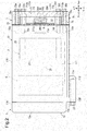
Fig. 1 is a rear view showing a motor-driven compressor according to an embodiment. -
Fig. 2 is a partial cross-sectional view taken along line 2-2 inFig. 1 . -
Fig. 3 is a rear view showing the housing of the motor-driven compressor ofFig. 1 . -
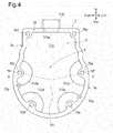
Fig. 4 is a front view showing the cover of the motor-driven compressor ofFig. 1 . -
Fig. 5 is an enlarged view of the cross section taken along line 5-5 inFig. 4 . - Throughout the drawings and the detailed description, the same reference numerals refer to the same elements. The drawings may not be to scale, and the relative size, proportions, and depiction of elements in the drawings may be exaggerated for clarity, illustration, and convenience.
- This description provides a comprehensive understanding of the methods, apparatuses, and/or systems described. Modifications and equivalents of the methods, apparatuses, and/or systems described are apparent to one of ordinary skill in the art. Sequences of operations are exemplary, and may be changed as apparent to one of ordinary skill in the art, with the exception of operations necessarily occurring in a certain order. Descriptions of functions and constructions that are well known to one of ordinary skill in the art may be omitted.
- Exemplary embodiments may have different forms, and are not limited to the examples described. However, the examples described are thorough and complete, and convey the full scope of the disclosure to one of ordinary skill in the art.
- A motor-driven compressor according to an embodiment will now be described with reference to the drawings. This compressor is installed in a vehicle and configures a refrigeration circuit of a vehicle air conditioner.
- As shown in
Figs. 1 and2 , the motor-driven compressor of the present embodiment includes ahousing 1, a motor-drivencompressor 3, acompression mechanism 5, acover 7, aninverter 9, and apositioner 31. Thehousing 1 includes afirst housing member 11 and asecond housing member 13. - In the present embodiment, the upper, lower, left, and right directions of the motor-driven compressor are defined using coordinate axes shown in
Fig. 1 . InFigs. 2 to 5 , the upper, lower, left, and right directions are defined using coordinate axes corresponding toFig. 1 . InFigs. 2 and5 , the front-rear direction of the motor-driven compressor is defined such that the side where thesecond housing member 13 is located relative to thefirst housing member 11 is set as the front and the side where thecover 7 is located relative to thefirst housing member 11 is set as the rear. These directions are merely examples to aid explanation. The position of the motor-driven compressor is changed in correspondence with the vehicle or the like in which the motor-driven compressor is installed. - Referring to
Fig. 2 , thefirst housing member 11 is made of aluminum alloy. Thefirst housing member 11 includes afirst end wall 11a (first bottom wall), a firstcircumferential wall 11b (first side wall), and afirst flange 11c. Thefirst end wall 11a is the rear end of thefirst housing member 11 and extends in the radial direction of the motor-driven compressor. The firstcircumferential wall 11b is continuous with thefirst end wall 11a and extends frontward from thefirst end wall 11a along the axis of the motor-driven compressor. Thefirst end wall 11a is an end wall that closes the rear end of the firstcircumferential wall 11b, and the front end of the firstcircumferential wall 11b opens. Thefirst housing member 11 is hollow and opens frontward. Thefirst flange 11c is formed integrally with the firstcircumferential wall 11b and protrudes from the firstcircumferential wall 11b toward the right side of the motor-driven compressor. Thefirst flange 11c includes afirst insertion hole 110. - As shown in
Fig. 3 , thefirst housing member 11 includes amotor accommodation portion 111 and abridge 113. Themotor accommodation portion 111 is a lower portion of thefirst housing member 11. Themotor accommodation portion 111 is substantially tubular. Themotor accommodation portion 111 has an inlet (not shown), which opens in the firstcircumferential wall 11b. Thebridge 113 is continuous with themotor accommodation portion 111 and located on the upper side of themotor accommodation portion 111. Thebridge 113 is an upper portion of thefirst housing member 11. Thebridge 113 has the form of a substantially rectangular box. The shapes of themotor accommodation portion 111 and thebridge 113 can be changed. - The
first housing member 11 includes first to sixth housing-side insertion holes 15a to 15f and aconnection port 17. Thefirst housing member 11 includes first and second fitting pins 19a and 19b (positioning pins). The first and second fitting pins 19a and 19b are examples of fitting portions. - As shown in
Fig. 3 , each of the first to sixth housing-side insertion holes 15a to 15f extends in the axial direction of thefirst housing member 11, that is, in the front-rear direction of the motor-driven compressor, in thefirst end wall 11a and the firstcircumferential wall 11b. Each of the first to sixth housing-side insertion holes 15a to 15f opens in thefirst end wall 11a. As shown inFig. 3 , the first to fourth housing-side insertion holes 15a to 15d are located at the lower portion of thefirst housing member 11, that is, located at themotor accommodation portion 111. The first to fourth housing-side insertion holes 15a to 15d are laid out in the circumferential direction of themotor accommodation portion 111 to surround theelectric motor 3. The fifth and sixth housing-side insertion holes bridge 113, which is the upper portion of thefirst housing member 11. The fifth housing-side insertion hole 15e is located on the left end of thebridge 113, and the sixth housing-side insertion hole 15f is located on the right end of thebridge 113. - The
connection port 17 is located between the fifth housing-side insertion hole 15e and the sixth housing-side insertion hole 15f in thefirst end wall 11a. The inside of thebridge 113 is connected to themotor accommodation portion 111 through theconnection port 17. A sealingmember 21 is arranged in theconnection port 17. - The first and second fitting pins 19a and 19b are partially embedded in the
first end wall 11a and fitted to thefirst end wall 11a. The first and second fitting pins 19a and 19b extend rearward from thefirst end wall 11a. That is, the first and second fitting pins 19a and 19b extend from thefirst end wall 11a toward acircumferential wall 73 of thecover 7 along the axis of thefirst housing member 11. Thecircumferential wall 73 will be described later. - The first and second fitting pins 19a and 19b are located at the
motor accommodation portion 111, which is the lower portion of thefirst housing member 11. More specifically, the firstfitting pin 19a is located proximate to the left end of themotor accommodation portion 111 and between the first housing-side insertion hole 15a and the third housing-side insertion hole 15c. The secondfitting pin 19b is located proximate to the right end of themotor accommodation portion 111 and between the second housing-side insertion hole 15b and the fourth housing-side insertion hole 15d. The secondfitting pin 19b is located slightly above the firstfitting pin 19a in themotor accommodation portion 111. - Referring to
Fig. 2 , thesecond housing member 13 is made of aluminum alloy. Thesecond housing member 13 includes asecond end wall 13a (second bottom wall), a secondcircumferential wall 13b (second side wall), and asecond flange 13c. Thesecond end wall 13a is located at the front end of thesecond housing member 13 and extends in the radial direction of the motor-driven compressor. The secondcircumferential wall 13b extends rearward from thesecond end wall 13a along the axis of the motor-driven compressor. Thesecond housing member 13, which includes thesecond end wall 13a and the secondcircumferential wall 13b, has a tubular shape and opens rearward. Although not illustrated in detail in the drawings, thesecond housing member 13 has a shape corresponding to the shape of thefirst housing member 11. That is, thesecond housing member 13 has a substantially tubular lower portion and a substantially box-shaped upper portion. Thesecond flange 13c protrudes rightward from the secondcircumferential wall 13b. Thesecond flange 13c includes asecond insertion hole 130. - The
second housing member 13 is located in front of thefirst housing member 11 with thesecond flange 13c aligned to thefirst flange 11c of thefirst housing member 11. Thefirst housing member 11 and thesecond housing member 13 are fastened to each other by bolts (not shown) in addition to abolt 23, which is inserted through the first and second insertion holes 110 and 130. Thus, thefirst housing member 11 and thesecond housing member 13 are integrated with each other. The first andsecond housing members - The motor-driven
compressor 3 is accommodated in themotor accommodation portion 111 of thefirst housing member 11. The motor-drivencompressor 3 includes astator 25, arotor 27, adrive shaft 29, and a connection portion (not shown). Thestator 25 is fixed to the inner circumferential surface of the firstcircumferential wall 11b in themotor accommodation portion 111. Thestator 25 includes coils (not shown). Therotor 27 is arranged on the inner circumferential side of thestator 25. Thedrive shaft 29 is fixed to therotor 27 such that thedrive shaft 29 rotates integrally with therotor 27. The connection portion is connected to a cluster block (not shown), which is accommodated in thebridge 113. The cluster block is connected to a connection terminal (not shown) in thebridge 113. - The
compression mechanism 5 is located in front of theelectric motor 3 in themotor accommodation portion 111. Thecompression mechanism 5 is a typical scroll compression mechanism. Thecompression mechanism 5 includes a fixed scroll, which is fixed to the inner circumferential surface of the firstcircumferential wall 11b, and a movable scroll, which is opposed to the fixed scroll. The movable scroll is connected to thedrive shaft 29 such that power can be transmitted from the movable scroll to thedrive shaft 29. The movable scroll is rotated by thedrive shaft 29. The fixed scroll meshes with the movable scroll. A compression chamber is defined between the fixed scroll and the movable scroll. A discharge chamber is defined between the fixed scroll and thesecond housing member 13. The fixed scroll, the movable scroll, the compression chamber, and the discharge chamber are not illustrated in the drawings. Thecompression mechanism 5 may be a vane-type compression mechanism. - Referring to
Figs. 4 and5 , thecover 7 is made of, for example, aluminum alloy. Thecover 7 includes abody wall 71, thecircumferential wall 73, and first to sixth cover-side insertion holes 75a to 75f. The first to sixth cover-side insertion holes 75a to 75f are examples of insertion holes. Thecover 7 may be made of plastic. - As shown in
Fig. 5 , thebody wall 71 is the rear end of thecover 7 and extends in the radial direction of the motor-driven compressor. Thebody wall 71 is plate-shaped and includes afirst surface 71a and asecond surface 71b. Thefirst surface 71a is a front surface. Thesecond surface 71b is a rear surface located on the side opposite from thefirst surface 71a and oriented toward the outside of the motor-driven compressor. The detail of thebody wall 71 will be described later. - As shown in
Fig. 4 , thecircumferential wall 73 is integrated with thebody wall 71 along the entire outer edge of thefirst surface 71a. As shown inFig. 2 , thecircumferential wall 73 extends frontward from thebody wall 71 toward thefirst housing member 11 along the axis of thecover 7. Thecover 7, which includes thebody wall 71 and thecircumferential wall 73, has a substantially tubular shape and opens frontward. Thecover 7 is shaped in correspondence with thefirst housing member 11. That is, thecover 7 includes a substantially tubularfirst part 7a, which corresponds to themotor accommodation portion 111, and a substantially tubularsecond part 7b, which corresponds to thebridge 113. The shape of thecover 7 can be changed in accordance with the shapes of thefirst housing member 11, theinverter 9, and the like. - The
circumferential wall 73 has a throughhole 711a. The throughhole 711a extends through thecircumferential wall 73 in the vertical direction, and an accommodation chamber 37 (described later) is connected to the exterior of thecover 7 through the throughhole 711a. Thecircumferential wall 73 is integrated with aconnector 715. Theconnector 715 is substantially box-shaped to surround the throughhole 711a and protrudes upward from thecircumferential wall 73. The throughhole 711a and theconnector 715 may be included in thebody wall 71. - The
body wall 71 and thecircumferential wall 73 include the first to sixth cover-side insertion holes 75a to 75f. More specifically, the first to sixth cover-side insertion holes 75a to 75f are arranged along the periphery of thebody wall 71 and extended through thebody wall 71 and thecircumferential wall 73 in the axial direction of thecover 7. The first to sixth cover-side insertion holes 75a to 75f are respectively located at positions corresponding to the first to sixth housing-side insertion holes 15a to 15f, which are shown inFig. 3 . That is, as shown inFig. 4 , the first to fourth cover-side insertion holes 75a to 75d are located at thefirst part 7a and laid out in the circumferential direction of thefirst part 7a. The first to fourth cover-side insertion holes 75a to 75d are specific insertion holes. The fifth and sixth cover-side insertion holes second part 7b of thecover 7. The fifth cover-side insertion hole 75e is located on the left end of thesecond part 7b, and the sixth cover-side insertion hole 75f is located on the right end of thesecond part 7b. - The
body wall 71 includes afirst thickness portion 711 andsecond thickness portions 713a to 713d. The proportion of thefirst thickness portion 711 accounting for thebody wall 71 is larger than the proportions of thesecond thickness portions 713a to 713d accounting for thebody wall 71. In other words, most of thebody wall 71 is thefirst thickness portion 711. As shown inFig. 5 , the thickness of thefirst thickness portion 711 is a first thickness T1. - As shown in
Fig. 4 , thesecond thickness portion 713a is arranged to surround the first cover-side insertion hole 75a. More specifically, thesecond thickness portion 713a is substantially sectoral and extends around the first cover-side insertion hole 75a to be concentric with the first cover-side insertion hole 75a, and the opposite ends of thesecond thickness portion 713a in the circumferential direction connect to thecircumferential wall 73. In the same manner, thesecond thickness portions 713b to 713d are arranged to surround the second to fourth cover-side insertion holes 75b to 75d, respectively. Thesecond thickness portions 713b to 713d are substantially sectoral and extend around the second to fourth cover-side insertion hole 75b to 75d to be concentric with the second to fourth cover-side insertion hole 75b to 75d, and the opposite ends of each of thesecond thickness portions 713b to 713d in the circumferential direction connect to thecircumferential wall 73. Thesecond thickness portions 713a to 713d are arranged to surround thebody wall 71 in thefirst part 7a of thecover 7. - The
second thickness portions 713a to 713d define a central portion C in thebody wall 71. The central portion C is located at a position of thefirst thickness portion 711 closer to the center of thebody wall 71 than to thesecond thickness portions 713a to 713d. Since the thickness of thefirst thickness portion 711 is the first thickness T1, the thickness of the central portion C is the first thickness T1. - As shown in
Fig. 5 , thebody wall 71 includes multiple (for example, four) recesses that are recessed from thefirst surface 71a toward thesecond surface 71b. The portions between the inner bottom surfaces of the recesses and thesecond surface 71b are thesecond thickness portions 713a to 713d. Thesecond thickness portions 713b to 713d have a second thickness T2, which is smaller than the first thickness T1. The second thickness T2 may be approximately half of the first thickness T1. In thebody wall 71, the rigidity of thesecond thickness portions 713b to 713d, which have a small thickness, is lower than that of thefirst thickness portion 711. As long as the second thickness T2 is smaller than the first thickness T1, the second thickness T2 can be changed. - As shown in
Fig. 4 , thecircumferential wall 73 of thecover 7 includes first and secondfitted recesses fitted recesses Fig. 1 , thepositioners 31 include the first and second fitting pins 19a and 19b and the first and secondfitted portions - As shown in
Fig. 4 , each of the first and secondfitted recesses circumferential wall 73 and extends toward the rear of the motor-driven compressor along the axis of thecover 7. The first and second fitting pins 19a and 19b can be inserted through the first and secondfitted recesses fitted recesses fitted recesses body wall 71. - The first and second
fitted recesses fitted recess 77a is arranged between the first cover-side insertion hole 75a and the third cover-side insertion hole 75c in thecircumferential wall 73, and the secondfitted recess 77b is arranged between the second cover-side insertion hole 75b and the fourth cover-side insertion hole 75d in thecircumferential wall 73. - The first
fitted recess 77a is adjacent to thesecond thickness portion 713c, and the secondfitted recess 77b is adjacent to thesecond thickness portion 713b. More specifically, as shown inFig. 4 , the firstfitted recess 77a is located at a portion of thecircumferential wall 73 to which the left end of the arcuate outer edge of thesecond thickness portion 713c is connected, and the secondfitted recess 77b is located at a portion of thecircumferential wall 73 to which the lower end of the arcuate outer edge of thesecond thickness portion 713b is connected. - As shown in
Fig. 2 , thecover 7 is located behind thefirst housing member 11 such that thefirst surface 71a of thebody wall 71 is opposed to thefirst end wall 11a of thefirst housing member 11. Agasket 33 may be arranged between thecover 7 and thefirst housing member 11. - As shown in
Fig. 1 , the motor-driven compressor of the present embodiment includes the firstfitting pin 19a, which is inserted through the firstfitted recess 77a, and the secondfitting pin 19b, which is inserted through the secondfitted recess 77b. The first and second fitting pins 19a and 19b are fitted to the first and secondfitted recesses Fig. 2 , thefirst housing member 11 and thecover 7 are positioned with the first to sixth housing-side insertion holes 15a to 15f aligned to the first to sixth cover-side insertion holes 75a to 75f, respectively. - With the
first housing member 11 positioned relative to thecover 7, thecover 7 is fastened to thefirst housing member 11 by the first tosixth bolts 35a to 35f, which are shown inFig. 1 . The first tosixth bolts 35a to 35f are examples of fasteners. More specifically, thefirst bolt 35a is inserted through the first cover-side insertion hole 75a and the first housing-side insertion hole 15a from thesecond surface 71b of thebody wall 71. In the same manner, thesecond bolt 35b is inserted through the second cover-side insertion hole 75b and the second housing-side insertion hole 15b. Thethird bolt 35c is inserted through the third cover-side insertion hole 75c and the third housing-side insertion hole 15c. Thefourth bolt 35d is inserted through the fourth cover-side insertion hole 75d and the fourth housing-side insertion hole 15d. Thefifth bolt 35e is inserted through the fifth cover-side insertion hole 75e and the fifth housing-side insertion hole 15e. Thesixth bolt 35f is inserted through the sixth cover-side insertion hole 75f and the sixth housing-side insertion hole 15f. In this manner, thefirst part 7a of thecover 7 is fastened to themotor accommodation portion 111 of thefirst housing member 11 by the first tofourth bolts 35a to 35d, and thesecond part 7b of thecover 7 is fastened to thebridge 113 of thefirst housing member 11 by the fifth andsixth bolts sixth bolts 35a to 35f, the first tofourth bolts 35a to 35d are specific fasteners. The number of the first tosixth bolts 35a to 35f can be changed in accordance with the sizes and the like of thefirst housing member 11 and thecover 7. Consequently, the number of the first to sixth cover-side insertion holes 75a to 75f and the number of the first to sixth housing-side insertion holes 15a to 15f can be changed in accordance with the sizes and the like of thefirst housing member 11 and thecover 7. - In this manner, when the
cover 7 is fastened to thefirst housing member 11, theaccommodation chamber 37 is defined between thefirst end wall 11a and thefirst surface 71a as shown inFig. 2 . Theaccommodation chamber 37, which is surrounded by thecircumferential wall 73, is isolated from the outside of the motor-driven compressor except the throughhole 711a. Thegasket 33 seals a part between theaccommodation chamber 37 and thefirst housing member 11. - The
inverter 9 is fixed to thefirst end wall 11a and accommodated in theaccommodation chamber 37. In theaccommodation chamber 37, theinverter 9 is opposed to thefirst surface 71a of thebody wall 71. Although not illustrated in detail in the drawings, theinverter 9 includes a circuit board, semiconductor elements, which are arranged on the circuit board, and a lead wire, which is connected to the circuit board. The lead wire extends into thebridge 113 through theconnection port 17, which is shown inFig. 3 , and is connected to the connection terminal. This connects theinverter 9 to theelectric motor 3. - As shown in
Fig. 2 , apower supply assembly 39 is arranged in the throughhole 711a of thecover 7. Thepower supply assembly 39 is formed by insert-molding afirst terminal 391, asecond terminal 392, and abus bar 393 into an insulatingplastic 394. Thepower supply assembly 39 is connected to theinverter 9 by thebus bar 393 in theaccommodation chamber 37. - In the above-described motor-driven compressor, the
connector 715 of thecover 7 is connected to a power supply (not shown), which is located outside the motor-driven compressor, by a cable (not shown). This supplies direct-current power from the power supply through thepower supply assembly 39 to theinverter 9. Theinverter 9 controls the driving of theelectric motor 3 by converting the direct-current power into alternating-current power and supplying theelectric motor 3 with the alternating-current power. When theelectric motor 3 is supplied with the alternating-current power, therotor 27 and thedrive shaft 29 rotate. This drives thecompression mechanism 5. Thecompression mechanism 5 compresses refrigerant gas drawn in from the inlet and discharges the compressed refrigerant gas out of the discharge port. The refrigerant gas is an example of fluid. - The
cover 7 of the motor-driven compressor is fastened to thefirst housing member 11 by the first tosixth bolts 35a to 35f, which are inserted through the first to sixth cover-side insertion holes 75a to 75f. Thus, when theelectric motor 3 and thecompression mechanism 5 are operating, vibration of thefirst housing member 11 can be transmitted through the first tosixth bolts 35a to 35f to thecover 7. In particular, the vibration of thefirst housing member 11 is easily transmitted through the first tosixth bolts 35a to 35f to the surroundings of the first to sixth cover-side insertion holes 75a to 75f. Additionally, since theelectric motor 3 is accommodated in themotor accommodation portion 111 of thefirst housing member 11, the vibration of thefirst housing member 11 is easily transmitted through the first tofourth bolts 35a to 35d to the surroundings of the first to fourth cover-side insertion holes 75a to 75d in thefirst part 7a of thecover 7. - The first to sixth cover-
side insertion holes 75a to 75f of the motor-driven compressor are arranged on the periphery of thebody wall 71. Further, thebody wall 71 includes thefirst thickness portion 711 and thesecond thickness portions 713a to 713d. Thesecond thickness portions 713a to 713d have the second thickness T2, which is smaller than the first thickness T1 of thefirst thickness portion 711. Thesecond thickness portions 713a to 713d are arranged around the first to fourth cover-side insertion holes 75a to 75d, respectively. Thesecond thickness portions 713a to 713d, which respectively surround the first to fourth cover-side insertion holes 75a to 75d, partially reduce the rigidity of thebody wall 71. That is, the rigidity of the periphery is low in thebody wall 71 of the motor-driven compressor. By contrast, thefirst thickness portion 711 has the first thickness T1, which is larger than the thickness of thesecond thickness portions 713a to 713d. Thus, thefirst thickness portion 711 including the central portion C of thebody wall 71 has a higher rigidity than the periphery of thebody wall 71, except the periphery of thebody wall 71. Further, thefirst thickness portion 711 has a large proportion of thebody wall 71, and thus sufficiently increases the rigidity of thebody wall 71 and consequently increases the overall rigidity of thecover 7. - When the motor-driven compressor is operating, vibration of the
first housing member 11 easily vibrates thesecond thickness portions 713a to 713d of thecover 7. Thus, the vibration of thefirst housing member 11 can be easily absorbed by thesecond thickness portions 713a to 713d including themotor accommodation portion 111, that is, by the surrounding parts of the first to fourth cover-side insertion holes 75a to 75d. This limits the transmission of vibration of thefirst housing member 11 to the central portion C of thebody wall 71 and limits vibration of the central portion C of thebody wall 71 when the motor-driven compressor is operating. Noise resulting from the vibration occurs at the central portion C. Accordingly, when the surrounding parts of the first to fourth cover-side insertion holes 75a to 75d are intentionally vibrated by thesecond thickness portions 713a to 713d and the vibration at the central portion C is limited, noise hardly occurs even if the vibration of thefirst housing member 11 is transmitted to thecover 7 during operation of the motor-driven compressor. - The
second thickness portions 713a to 713d are recessed from thefirst surface 71a toward thesecond surface 71b. Thus, the arrangement of thesecond thickness portions 713a to 713d does not reduce the size of theaccommodation chamber 37. This eliminates the need to enlarge thecover 7 in the axial direction in order to obtain alarge accommodation chamber 37 in the motor-driven compressor. - When the
cover 7 is fastened to thefirst housing member 11, thesecond thickness portions 713a to 713d are located in theaccommodation chamber 37. This limits deposition of foreign matter such as dust and salt in thesecond thickness portions 713a to 713d. Thesecond surface 71b, which is exposed to the outside of the motor-driven compressor, is flat. This limits deposition of foreign matter in thesecond surface 71b and thus limits corrosion of thecover 7 of the motor-driven compressor. - Accordingly, the motor-driven compressor of the present embodiment reduces noise produced during operation of the motor-driven compressor and reduces the motor-driven compressor in size and weight.
- Particularly, the
second thickness portions 713a to 713d, which are substantially sectoral, connect to thecircumferential wall 73 while respectively surrounding the first to fourth cover-side insertion holes 75a to 75d. This limits the transmission of vibration of thefirst housing member 11 to the central portion C of thebody wall 71 while minimizing the proportions of thesecond thickness portions 713a to 713d accounting for thebody wall 71. This thus limits the transmission of vibration of thefirst housing member 11 to the central portion C of thebody wall 71 during operation of the motor-driven compressor while obtaining the rigidity of thecover 7. - The
circumferential wall 73 of thecover 7 separates the outside of the motor-driven compressor and theaccommodation chamber 37 from each other. Further, as compared to when thefirst housing member 11 has a circumferential wall extending toward thecover 7, the shape of thefirst housing member 11 is not complicated. This facilitates shaping of thefirst housing member 11. - Further, the
positioners 31 are used to facilitate positioning of thefirst housing member 11 and thecover 7, thereby facilitating fastening of thefirst housing member 11 and thecover 7 to each other. Thepositioners 31 include the first and second fitting pins 19a and 19b and the first and secondfitted recesses fitted recess 77a is adjacent to thesecond thickness portion 713c, and the secondfitted recess 77b is adjacent to thesecond thickness portion 713b. Thus, the first and second fitting pins 19a and 19b and the first and secondfitted recesses first housing member 11 to the central portion C of thebody wall 71. - The above-described embodiment is intended only for description, not for limitation. The above-described embodiment may be modified within the claims and the scope thereof.
- For example, the shape of the
second thickness portions 713a to 713d may be changed to a shape other than a substantially sectoral shape. Further, thesecond thickness portions 713a to 713d may have different shapes. - In addition, the
body wall 71 may include second thickness portions located around the fifth and sixth cover-side insertion holes second thickness portions 713a to 713d. - Alternatively, the
body wall 71 may include thesecond thickness portion 713a around only one of the first to sixth cover-side insertion holes 75a to 75f. - Further, in order to prevent the heads of the first to sixth cover-
side insertion holes 75a to 75f from protruding toward the rear side of thecover 7, thesecond surface 71b of thebody wall 71 may include recesses that surround the first to sixth cover-side insertion holes 75a to 75f. - Instead of the
circumferential wall 73 of thecover 7, thefirst housing member 11 may include a circumferential wall extending toward thecover 7 while surrounding thefirst end wall 11a. - The
first end wall 11a may include only the firstfitting pin 19a or may include an additional fitting pin in addition to the first and second fitting pins 19a and 19b. Further, the firstfitting pin 19a may be arranged at themotor accommodation portion 111, and the secondfitting pin 19b may be arranged at thebridge 113. Alternatively, the first and second fitting pins 19a and 19b may both be arranged at thebridge 113. - The
compression mechanism 5 may compress fluid other than refrigerant gas. - The present disclosure is applicable to the air conditioner for, for example, a vehicle.
- Various changes in form and details may be made to the examples above without departing from the spirit and scope of the claims and their equivalents. The examples are for the sake of description only, and not for purposes of limitation. Descriptions of features in each example are to be considered as being applicable to similar features or aspects in other examples. Suitable results may be achieved if sequences are performed in a different order, and/or if components in a described system, architecture, device, or circuit are combined differently, and/or replaced or supplemented by other components or their equivalents. The scope of the disclosure is not defined by the detailed description, but by the claims and their equivalents. All variations within the scope of the claims and their equivalents are included in the disclosure.
- A motor-driven compressor includes a compression mechanism, an electric motor, an inverter, a housing, and a cover defining an accommodation chamber with the housing to accommodate the inverter. The cover includes a plate-shaped body wall and insertion holes extending through a periphery of the body wall. The body wall includes a first surface opposed to the inverter in the accommodation chamber, a second surface, a first thickness portion having a first thickness, and a second thickness portion located around at least one of the insertion holes. The second thickness portion has a second thickness that is smaller than the first thickness and is obtained by recessing the body wall from the first surface toward the second surface.
Claims (4)
- A motor-driven compressor comprising:a compression mechanism (5) configured to compress fluid;an electric motor (3) configured to drive the compression mechanism (5);an inverter (9) configured to control driving of the electric motor (3);a housing (1) that accommodates the compression mechanism (5) and the electric motor (3); anda cover (7) fastened to the housing (1) by fasteners (35a, 35b, 35c, 35d, 35e, 35f), the cover (7) defining an accommodation chamber (37) with the housing (1) to accommodate the inverter (9), whereinthe cover (7) includesa plate-shaped body wall (71), andinsertion holes (75a, 75b, 75c, 75d, 75e, 75f) extending through a periphery of the body wall (71), the fasteners (35a, 35b, 35c, 35d, 35e, 35f) being inserted through the insertion holes (75a, 75b, 75c, 75d, 75e, 75f), andthe body wall (71) includesa first surface (71a) opposed to the inverter (9) in the accommodation chamber (37),a second surface (71b) located at a side opposite from the first surface (71a),a first thickness portion (711) having a first thickness (T1), anda second thickness portion (713a, 713b, 713c, 713d) located around at least one of the insertion holes (75a, 75b, 75c, 75d, 75e, 75f), wherein the second thickness portion (713a, 713b, 713c, 713d) has a second thickness (T2) that is smaller than the first thickness (T1) and is obtained by recessing the body wall (71) from the first surface (71a) toward the second surface (71b).
- The motor-driven compressor according to claim 1, wherein
the housing (1) includes a motor accommodation portion (111) that accommodates the electric motor (3),
the fasteners (35a, 35b, 35c, 35d, 35e, 35f) include specific fasteners (35a, 35b, 35c, 35d) that fasten the cover (7) to the motor accommodation portion (111),
the insertion holes (75a, 75b, 75c, 75d, 75e, 75f) include specific insertion holes (75a, 75b, 75c, 75d) through which the specific fasteners (35a, 35b, 35c, 35d) are inserted, and
each of the second thickness portions (713a, 713b, 713c, 713d) is arranged around a corresponding one of the specific insertion holes (75a, 75b, 75c, 75d). - The motor-driven compressor according to claim 1 or 2, wherein
the cover (7) includes a circumferential wall (73) extending from an outer edge of the body wall (71) toward the housing (1),
the insertion holes (75a, 75b, 75c, 75d, 75e, 75f) extend through the body wall (71) and the circumferential wall (73),
each of the second thickness portions (713a, 713b, 713c, 713d) extends around a corresponding one of the insertion holes (75a, 75b, 75c, 75d, 75e, 75f) to be concentric to the insertion hole (75a, 75b, 75c, 75d, 75e, 75f), and
opposite ends of the second thickness portion (713a, 713b, 713c, 713d) in a circumferential direction connect to the circumferential wall (73). - The motor-driven compressor according to claim 3, further comprising a positioner (31) that positions the housing (1) and the cover (7), wherein
the positioner (31) includes a fitting portion (19a, 19b) provided in the housing (1) and a fitted portion (77a, 77b) provided in the circumferential wall (73) and fitted to the fitting portion (19a, 19b), and
the fitted portion (77a, 77b) is adjacent to the second thickness portion (713a, 713b, 713c, 713d).
Applications Claiming Priority (1)
| Application Number | Priority Date | Filing Date | Title |
|---|---|---|---|
| JP2018205907A JP7040406B2 (en) | 2018-10-31 | 2018-10-31 | Electric compressor |
Publications (2)
| Publication Number | Publication Date |
|---|---|
| EP3647592A1 true EP3647592A1 (en) | 2020-05-06 |
| EP3647592B1 EP3647592B1 (en) | 2022-11-30 |
Family
ID=68281141
Family Applications (1)
| Application Number | Title | Priority Date | Filing Date |
|---|---|---|---|
| EP19203505.3A Active EP3647592B1 (en) | 2018-10-31 | 2019-10-16 | Motor-driven compressor |
Country Status (5)
| Country | Link |
|---|---|
| US (1) | US11424660B2 (en) |
| EP (1) | EP3647592B1 (en) |
| JP (1) | JP7040406B2 (en) |
| KR (1) | KR102265656B1 (en) |
| CN (1) | CN111120327B (en) |
Families Citing this family (4)
| Publication number | Priority date | Publication date | Assignee | Title |
|---|---|---|---|---|
| JP7040406B2 (en) * | 2018-10-31 | 2022-03-23 | 株式会社豊田自動織機 | Electric compressor |
| CN114427534B (en) * | 2020-10-29 | 2025-11-18 | 谷轮环境科技(苏州)有限公司 | compressor |
| US12497966B2 (en) | 2020-10-29 | 2025-12-16 | Copeland Climate Technologies (Suzhou) Co. Ltd. | Compressor with bottom cover and bearing block arrangement |
| KR20230137148A (en) * | 2022-03-21 | 2023-10-04 | 한온시스템 주식회사 | Electric compressor |
Citations (4)
| Publication number | Priority date | Publication date | Assignee | Title |
|---|---|---|---|---|
| EP2325488A1 (en) * | 2008-09-01 | 2011-05-25 | Kabushiki Kaisha Toyota Jidoshokki | Electric compressor |
| JP2013177826A (en) | 2012-02-28 | 2013-09-09 | Mitsubishi Heavy Ind Ltd | Electric compressor |
| US20150054365A1 (en) * | 2013-08-23 | 2015-02-26 | Kabushiki Kaisha Toyota Jidoshokki | Motor-driven compressor |
| WO2016167409A1 (en) * | 2015-04-17 | 2016-10-20 | 한온시스템 주식회사 | Electric compressor |
Family Cites Families (12)
| Publication number | Priority date | Publication date | Assignee | Title |
|---|---|---|---|---|
| JP5382036B2 (en) * | 2011-03-16 | 2014-01-08 | 株式会社豊田自動織機 | Electric compressor |
| KR20130025649A (en) | 2011-09-02 | 2013-03-12 | 한라공조주식회사 | Electric motor-driven compressor |
| JP6098128B2 (en) * | 2012-11-15 | 2017-03-22 | 株式会社豊田自動織機 | Electric compressor |
| JP6258615B2 (en) * | 2013-07-12 | 2018-01-10 | サンデンホールディングス株式会社 | Electric compressor |
| KR102257795B1 (en) * | 2014-08-29 | 2021-05-28 | 한온시스템 주식회사 | Electric compressor |
| CN104265638B (en) * | 2014-09-18 | 2016-08-31 | 乔建设 | Low-voltage heavy current porting displaceable electric scroll compressor |
| JP2016151246A (en) | 2015-02-19 | 2016-08-22 | 株式会社ケーヒン | Motor driven compression device |
| KR102194807B1 (en) * | 2015-12-24 | 2020-12-23 | 한온시스템 주식회사 | Compressor |
| CN207777168U (en) * | 2017-04-28 | 2018-08-28 | 上海海立新能源技术有限公司 | A kind of compressor |
| CN106989018B (en) * | 2017-04-28 | 2020-06-02 | 上海海立新能源技术有限公司 | A kind of compressor |
| JP7040406B2 (en) * | 2018-10-31 | 2022-03-23 | 株式会社豊田自動織機 | Electric compressor |
| DE102020203260A1 (en) * | 2019-03-28 | 2020-10-01 | Kabushiki Kaisha Toyota Jidoshokki | ELECTRIC COMPRESSOR |
-
2018
- 2018-10-31 JP JP2018205907A patent/JP7040406B2/en active Active
-
2019
- 2019-10-16 EP EP19203505.3A patent/EP3647592B1/en active Active
- 2019-10-28 CN CN201911032475.8A patent/CN111120327B/en active Active
- 2019-10-29 KR KR1020190135301A patent/KR102265656B1/en active Active
- 2019-10-29 US US16/666,875 patent/US11424660B2/en active Active
Patent Citations (4)
| Publication number | Priority date | Publication date | Assignee | Title |
|---|---|---|---|---|
| EP2325488A1 (en) * | 2008-09-01 | 2011-05-25 | Kabushiki Kaisha Toyota Jidoshokki | Electric compressor |
| JP2013177826A (en) | 2012-02-28 | 2013-09-09 | Mitsubishi Heavy Ind Ltd | Electric compressor |
| US20150054365A1 (en) * | 2013-08-23 | 2015-02-26 | Kabushiki Kaisha Toyota Jidoshokki | Motor-driven compressor |
| WO2016167409A1 (en) * | 2015-04-17 | 2016-10-20 | 한온시스템 주식회사 | Electric compressor |
Also Published As
| Publication number | Publication date |
|---|---|
| JP2020070763A (en) | 2020-05-07 |
| JP7040406B2 (en) | 2022-03-23 |
| KR20200049636A (en) | 2020-05-08 |
| CN111120327B (en) | 2022-07-12 |
| KR102265656B1 (en) | 2021-06-15 |
| EP3647592B1 (en) | 2022-11-30 |
| US20200136463A1 (en) | 2020-04-30 |
| US11424660B2 (en) | 2022-08-23 |
| CN111120327A (en) | 2020-05-08 |
Similar Documents
| Publication | Publication Date | Title |
|---|---|---|
| EP3647592B1 (en) | Motor-driven compressor | |
| US8618703B2 (en) | Motor driven compressor | |
| CN101463814B (en) | Motor-driven compressor | |
| EP2072754B1 (en) | Motor-driven compressor with multi-part casing | |
| JP4983714B2 (en) | Electric compressor | |
| US20090185921A1 (en) | Scroll Compressor Having Standardized Power Strip | |
| US20180091016A1 (en) | Electric compressor | |
| EP2325488A1 (en) | Electric compressor | |
| CN111120249B (en) | Electric compressor | |
| US6737773B2 (en) | Wiring structure of motor in hybrid compressor | |
| JP6766666B2 (en) | Electric compressor | |
| JP7366588B2 (en) | electric compressor | |
| EP2623786B1 (en) | Motor-driven compressor | |
| EP2623788B1 (en) | Motor-driven compressor | |
| EP2505775A2 (en) | Motor-driven compressor | |
| US20220320949A1 (en) | Fluid machine | |
| KR101986450B1 (en) | Motor-driven compressor | |
| JP4225101B2 (en) | Electric compressor | |
| CN111271260A (en) | Compressors and refrigeration equipment | |
| JP4924296B2 (en) | Electric compressor | |
| JP2017129056A (en) | Electric compressor | |
| CN114320831A (en) | Piston assembly, compressor assembly and refrigeration equipment | |
| JP2002327684A (en) | Hermetic reciprocating compressor | |
| JP2008274966A (en) | Electric compressor | |
| JP2004036416A (en) | Electric compressor |
Legal Events
| Date | Code | Title | Description |
|---|---|---|---|
| PUAI | Public reference made under article 153(3) epc to a published international application that has entered the european phase |
Free format text: ORIGINAL CODE: 0009012 |
|
| STAA | Information on the status of an ep patent application or granted ep patent |
Free format text: STATUS: REQUEST FOR EXAMINATION WAS MADE |
|
| 17P | Request for examination filed |
Effective date: 20191016 |
|
| AK | Designated contracting states |
Kind code of ref document: A1 Designated state(s): AL AT BE BG CH CY CZ DE DK EE ES FI FR GB GR HR HU IE IS IT LI LT LU LV MC MK MT NL NO PL PT RO RS SE SI SK SM TR |
|
| AX | Request for extension of the european patent |
Extension state: BA ME |
|
| GRAP | Despatch of communication of intention to grant a patent |
Free format text: ORIGINAL CODE: EPIDOSNIGR1 |
|
| STAA | Information on the status of an ep patent application or granted ep patent |
Free format text: STATUS: GRANT OF PATENT IS INTENDED |
|
| INTG | Intention to grant announced |
Effective date: 20220801 |
|
| GRAS | Grant fee paid |
Free format text: ORIGINAL CODE: EPIDOSNIGR3 |
|
| GRAA | (expected) grant |
Free format text: ORIGINAL CODE: 0009210 |
|
| STAA | Information on the status of an ep patent application or granted ep patent |
Free format text: STATUS: THE PATENT HAS BEEN GRANTED |
|
| AK | Designated contracting states |
Kind code of ref document: B1 Designated state(s): AL AT BE BG CH CY CZ DE DK EE ES FI FR GB GR HR HU IE IS IT LI LT LU LV MC MK MT NL NO PL PT RO RS SE SI SK SM TR |
|
| REG | Reference to a national code |
Ref country code: CH Ref legal event code: EP Ref country code: GB Ref legal event code: FG4D |
|
| REG | Reference to a national code |
Ref country code: AT Ref legal event code: REF Ref document number: 1534890 Country of ref document: AT Kind code of ref document: T Effective date: 20221215 |
|
| REG | Reference to a national code |
Ref country code: IE Ref legal event code: FG4D |
|
| REG | Reference to a national code |
Ref country code: DE Ref legal event code: R096 Ref document number: 602019022475 Country of ref document: DE |
|
| REG | Reference to a national code |
Ref country code: LT Ref legal event code: MG9D |
|
| REG | Reference to a national code |
Ref country code: NL Ref legal event code: MP Effective date: 20221130 |
|
| PG25 | Lapsed in a contracting state [announced via postgrant information from national office to epo] |
Ref country code: SE Free format text: LAPSE BECAUSE OF FAILURE TO SUBMIT A TRANSLATION OF THE DESCRIPTION OR TO PAY THE FEE WITHIN THE PRESCRIBED TIME-LIMIT Effective date: 20221130 Ref country code: PT Free format text: LAPSE BECAUSE OF FAILURE TO SUBMIT A TRANSLATION OF THE DESCRIPTION OR TO PAY THE FEE WITHIN THE PRESCRIBED TIME-LIMIT Effective date: 20230331 Ref country code: NO Free format text: LAPSE BECAUSE OF FAILURE TO SUBMIT A TRANSLATION OF THE DESCRIPTION OR TO PAY THE FEE WITHIN THE PRESCRIBED TIME-LIMIT Effective date: 20230228 Ref country code: LT Free format text: LAPSE BECAUSE OF FAILURE TO SUBMIT A TRANSLATION OF THE DESCRIPTION OR TO PAY THE FEE WITHIN THE PRESCRIBED TIME-LIMIT Effective date: 20221130 Ref country code: FI Free format text: LAPSE BECAUSE OF FAILURE TO SUBMIT A TRANSLATION OF THE DESCRIPTION OR TO PAY THE FEE WITHIN THE PRESCRIBED TIME-LIMIT Effective date: 20221130 Ref country code: ES Free format text: LAPSE BECAUSE OF FAILURE TO SUBMIT A TRANSLATION OF THE DESCRIPTION OR TO PAY THE FEE WITHIN THE PRESCRIBED TIME-LIMIT Effective date: 20221130 |
|
| REG | Reference to a national code |
Ref country code: AT Ref legal event code: MK05 Ref document number: 1534890 Country of ref document: AT Kind code of ref document: T Effective date: 20221130 |
|
| PG25 | Lapsed in a contracting state [announced via postgrant information from national office to epo] |
Ref country code: RS Free format text: LAPSE BECAUSE OF FAILURE TO SUBMIT A TRANSLATION OF THE DESCRIPTION OR TO PAY THE FEE WITHIN THE PRESCRIBED TIME-LIMIT Effective date: 20221130 Ref country code: PL Free format text: LAPSE BECAUSE OF FAILURE TO SUBMIT A TRANSLATION OF THE DESCRIPTION OR TO PAY THE FEE WITHIN THE PRESCRIBED TIME-LIMIT Effective date: 20221130 Ref country code: LV Free format text: LAPSE BECAUSE OF FAILURE TO SUBMIT A TRANSLATION OF THE DESCRIPTION OR TO PAY THE FEE WITHIN THE PRESCRIBED TIME-LIMIT Effective date: 20221130 Ref country code: IS Free format text: LAPSE BECAUSE OF FAILURE TO SUBMIT A TRANSLATION OF THE DESCRIPTION OR TO PAY THE FEE WITHIN THE PRESCRIBED TIME-LIMIT Effective date: 20230330 Ref country code: HR Free format text: LAPSE BECAUSE OF FAILURE TO SUBMIT A TRANSLATION OF THE DESCRIPTION OR TO PAY THE FEE WITHIN THE PRESCRIBED TIME-LIMIT Effective date: 20221130 Ref country code: GR Free format text: LAPSE BECAUSE OF FAILURE TO SUBMIT A TRANSLATION OF THE DESCRIPTION OR TO PAY THE FEE WITHIN THE PRESCRIBED TIME-LIMIT Effective date: 20230301 |
|
| P01 | Opt-out of the competence of the unified patent court (upc) registered |
Effective date: 20230519 |
|
| PG25 | Lapsed in a contracting state [announced via postgrant information from national office to epo] |
Ref country code: NL Free format text: LAPSE BECAUSE OF FAILURE TO SUBMIT A TRANSLATION OF THE DESCRIPTION OR TO PAY THE FEE WITHIN THE PRESCRIBED TIME-LIMIT Effective date: 20221130 |
|
| PG25 | Lapsed in a contracting state [announced via postgrant information from national office to epo] |
Ref country code: SM Free format text: LAPSE BECAUSE OF FAILURE TO SUBMIT A TRANSLATION OF THE DESCRIPTION OR TO PAY THE FEE WITHIN THE PRESCRIBED TIME-LIMIT Effective date: 20221130 Ref country code: RO Free format text: LAPSE BECAUSE OF FAILURE TO SUBMIT A TRANSLATION OF THE DESCRIPTION OR TO PAY THE FEE WITHIN THE PRESCRIBED TIME-LIMIT Effective date: 20221130 Ref country code: EE Free format text: LAPSE BECAUSE OF FAILURE TO SUBMIT A TRANSLATION OF THE DESCRIPTION OR TO PAY THE FEE WITHIN THE PRESCRIBED TIME-LIMIT Effective date: 20221130 Ref country code: DK Free format text: LAPSE BECAUSE OF FAILURE TO SUBMIT A TRANSLATION OF THE DESCRIPTION OR TO PAY THE FEE WITHIN THE PRESCRIBED TIME-LIMIT Effective date: 20221130 Ref country code: CZ Free format text: LAPSE BECAUSE OF FAILURE TO SUBMIT A TRANSLATION OF THE DESCRIPTION OR TO PAY THE FEE WITHIN THE PRESCRIBED TIME-LIMIT Effective date: 20221130 Ref country code: AT Free format text: LAPSE BECAUSE OF FAILURE TO SUBMIT A TRANSLATION OF THE DESCRIPTION OR TO PAY THE FEE WITHIN THE PRESCRIBED TIME-LIMIT Effective date: 20221130 |
|
| PG25 | Lapsed in a contracting state [announced via postgrant information from national office to epo] |
Ref country code: SK Free format text: LAPSE BECAUSE OF FAILURE TO SUBMIT A TRANSLATION OF THE DESCRIPTION OR TO PAY THE FEE WITHIN THE PRESCRIBED TIME-LIMIT Effective date: 20221130 Ref country code: AL Free format text: LAPSE BECAUSE OF FAILURE TO SUBMIT A TRANSLATION OF THE DESCRIPTION OR TO PAY THE FEE WITHIN THE PRESCRIBED TIME-LIMIT Effective date: 20221130 |
|
| REG | Reference to a national code |
Ref country code: DE Ref legal event code: R097 Ref document number: 602019022475 Country of ref document: DE |
|
| PLBE | No opposition filed within time limit |
Free format text: ORIGINAL CODE: 0009261 |
|
| STAA | Information on the status of an ep patent application or granted ep patent |
Free format text: STATUS: NO OPPOSITION FILED WITHIN TIME LIMIT |
|
| 26N | No opposition filed |
Effective date: 20230831 |
|
| PG25 | Lapsed in a contracting state [announced via postgrant information from national office to epo] |
Ref country code: SI Free format text: LAPSE BECAUSE OF FAILURE TO SUBMIT A TRANSLATION OF THE DESCRIPTION OR TO PAY THE FEE WITHIN THE PRESCRIBED TIME-LIMIT Effective date: 20221130 |
|
| PG25 | Lapsed in a contracting state [announced via postgrant information from national office to epo] |
Ref country code: IT Free format text: LAPSE BECAUSE OF FAILURE TO SUBMIT A TRANSLATION OF THE DESCRIPTION OR TO PAY THE FEE WITHIN THE PRESCRIBED TIME-LIMIT Effective date: 20221130 Ref country code: MC Free format text: LAPSE BECAUSE OF FAILURE TO SUBMIT A TRANSLATION OF THE DESCRIPTION OR TO PAY THE FEE WITHIN THE PRESCRIBED TIME-LIMIT Effective date: 20221130 |
|
| REG | Reference to a national code |
Ref country code: CH Ref legal event code: PL |
|
| REG | Reference to a national code |
Ref country code: BE Ref legal event code: MM Effective date: 20231031 |
|
| PG25 | Lapsed in a contracting state [announced via postgrant information from national office to epo] |
Ref country code: LU Free format text: LAPSE BECAUSE OF NON-PAYMENT OF DUE FEES Effective date: 20231016 |
|
| GBPC | Gb: european patent ceased through non-payment of renewal fee |
Effective date: 20231016 |
|
| PG25 | Lapsed in a contracting state [announced via postgrant information from national office to epo] |
Ref country code: LU Free format text: LAPSE BECAUSE OF NON-PAYMENT OF DUE FEES Effective date: 20231016 |
|
| PG25 | Lapsed in a contracting state [announced via postgrant information from national office to epo] |
Ref country code: GB Free format text: LAPSE BECAUSE OF NON-PAYMENT OF DUE FEES Effective date: 20231016 |
|
| PG25 | Lapsed in a contracting state [announced via postgrant information from national office to epo] |
Ref country code: CH Free format text: LAPSE BECAUSE OF NON-PAYMENT OF DUE FEES Effective date: 20231031 |
|
| PG25 | Lapsed in a contracting state [announced via postgrant information from national office to epo] |
Ref country code: GB Free format text: LAPSE BECAUSE OF NON-PAYMENT OF DUE FEES Effective date: 20231016 Ref country code: FR Free format text: LAPSE BECAUSE OF NON-PAYMENT OF DUE FEES Effective date: 20231031 Ref country code: CH Free format text: LAPSE BECAUSE OF NON-PAYMENT OF DUE FEES Effective date: 20231031 |
|
| PG25 | Lapsed in a contracting state [announced via postgrant information from national office to epo] |
Ref country code: BE Free format text: LAPSE BECAUSE OF NON-PAYMENT OF DUE FEES Effective date: 20231031 |
|
| PG25 | Lapsed in a contracting state [announced via postgrant information from national office to epo] |
Ref country code: IE Free format text: LAPSE BECAUSE OF NON-PAYMENT OF DUE FEES Effective date: 20231016 |
|
| PG25 | Lapsed in a contracting state [announced via postgrant information from national office to epo] |
Ref country code: IE Free format text: LAPSE BECAUSE OF NON-PAYMENT OF DUE FEES Effective date: 20231016 |
|
| PG25 | Lapsed in a contracting state [announced via postgrant information from national office to epo] |
Ref country code: BG Free format text: LAPSE BECAUSE OF FAILURE TO SUBMIT A TRANSLATION OF THE DESCRIPTION OR TO PAY THE FEE WITHIN THE PRESCRIBED TIME-LIMIT Effective date: 20221130 |
|
| PG25 | Lapsed in a contracting state [announced via postgrant information from national office to epo] |
Ref country code: BG Free format text: LAPSE BECAUSE OF FAILURE TO SUBMIT A TRANSLATION OF THE DESCRIPTION OR TO PAY THE FEE WITHIN THE PRESCRIBED TIME-LIMIT Effective date: 20221130 |
|
| PG25 | Lapsed in a contracting state [announced via postgrant information from national office to epo] |
Ref country code: CY Free format text: LAPSE BECAUSE OF FAILURE TO SUBMIT A TRANSLATION OF THE DESCRIPTION OR TO PAY THE FEE WITHIN THE PRESCRIBED TIME-LIMIT; INVALID AB INITIO Effective date: 20191016 |
|
| PG25 | Lapsed in a contracting state [announced via postgrant information from national office to epo] |
Ref country code: HU Free format text: LAPSE BECAUSE OF FAILURE TO SUBMIT A TRANSLATION OF THE DESCRIPTION OR TO PAY THE FEE WITHIN THE PRESCRIBED TIME-LIMIT; INVALID AB INITIO Effective date: 20191016 |
|
| PG25 | Lapsed in a contracting state [announced via postgrant information from national office to epo] |
Ref country code: TR Free format text: LAPSE BECAUSE OF FAILURE TO SUBMIT A TRANSLATION OF THE DESCRIPTION OR TO PAY THE FEE WITHIN THE PRESCRIBED TIME-LIMIT Effective date: 20221130 |
|
| PGFP | Annual fee paid to national office [announced via postgrant information from national office to epo] |
Ref country code: DE Payment date: 20250902 Year of fee payment: 7 |