EP3647546B1 - Module de soufflante a pales a calage variable - Google Patents
Module de soufflante a pales a calage variable Download PDFInfo
- Publication number
- EP3647546B1 EP3647546B1 EP19205722.2A EP19205722A EP3647546B1 EP 3647546 B1 EP3647546 B1 EP 3647546B1 EP 19205722 A EP19205722 A EP 19205722A EP 3647546 B1 EP3647546 B1 EP 3647546B1
- Authority
- EP
- European Patent Office
- Prior art keywords
- fan
- fan module
- blades
- rotor shaft
- control means
- Prior art date
- Legal status (The legal status is an assumption and is not a legal conclusion. Google has not performed a legal analysis and makes no representation as to the accuracy of the status listed.)
- Active
Links
Images

Classifications
-
- F—MECHANICAL ENGINEERING; LIGHTING; HEATING; WEAPONS; BLASTING
- F01—MACHINES OR ENGINES IN GENERAL; ENGINE PLANTS IN GENERAL; STEAM ENGINES
- F01D—NON-POSITIVE DISPLACEMENT MACHINES OR ENGINES, e.g. STEAM TURBINES
- F01D7/00—Rotors with blades adjustable in operation; Control thereof
-
- F—MECHANICAL ENGINEERING; LIGHTING; HEATING; WEAPONS; BLASTING
- F01—MACHINES OR ENGINES IN GENERAL; ENGINE PLANTS IN GENERAL; STEAM ENGINES
- F01D—NON-POSITIVE DISPLACEMENT MACHINES OR ENGINES, e.g. STEAM TURBINES
- F01D25/00—Component parts, details, or accessories, not provided for in, or of interest apart from, other groups
- F01D25/16—Arrangement of bearings; Supporting or mounting bearings in casings
-
- F—MECHANICAL ENGINEERING; LIGHTING; HEATING; WEAPONS; BLASTING
- F02—COMBUSTION ENGINES; HOT-GAS OR COMBUSTION-PRODUCT ENGINE PLANTS
- F02C—GAS-TURBINE PLANTS; AIR INTAKES FOR JET-PROPULSION PLANTS; CONTROLLING FUEL SUPPLY IN AIR-BREATHING JET-PROPULSION PLANTS
- F02C7/00—Features, components parts, details or accessories, not provided for in, or of interest apart form groups F02C1/00 - F02C6/00; Air intakes for jet-propulsion plants
- F02C7/06—Arrangements of bearings; Lubricating
-
- F—MECHANICAL ENGINEERING; LIGHTING; HEATING; WEAPONS; BLASTING
- F02—COMBUSTION ENGINES; HOT-GAS OR COMBUSTION-PRODUCT ENGINE PLANTS
- F02C—GAS-TURBINE PLANTS; AIR INTAKES FOR JET-PROPULSION PLANTS; CONTROLLING FUEL SUPPLY IN AIR-BREATHING JET-PROPULSION PLANTS
- F02C7/00—Features, components parts, details or accessories, not provided for in, or of interest apart form groups F02C1/00 - F02C6/00; Air intakes for jet-propulsion plants
- F02C7/36—Power transmission arrangements between the different shafts of the gas turbine plant, or between the gas-turbine plant and the power user
-
- F—MECHANICAL ENGINEERING; LIGHTING; HEATING; WEAPONS; BLASTING
- F02—COMBUSTION ENGINES; HOT-GAS OR COMBUSTION-PRODUCT ENGINE PLANTS
- F02K—JET-PROPULSION PLANTS
- F02K3/00—Plants including a gas turbine driving a compressor or a ducted fan
- F02K3/02—Plants including a gas turbine driving a compressor or a ducted fan in which part of the working fluid by-passes the turbine and combustion chamber
- F02K3/04—Plants including a gas turbine driving a compressor or a ducted fan in which part of the working fluid by-passes the turbine and combustion chamber the plant including ducted fans, i.e. fans with high volume, low pressure outputs, for augmenting the jet thrust, e.g. of double-flow type
- F02K3/06—Plants including a gas turbine driving a compressor or a ducted fan in which part of the working fluid by-passes the turbine and combustion chamber the plant including ducted fans, i.e. fans with high volume, low pressure outputs, for augmenting the jet thrust, e.g. of double-flow type with front fan
-
- F—MECHANICAL ENGINEERING; LIGHTING; HEATING; WEAPONS; BLASTING
- F04—POSITIVE - DISPLACEMENT MACHINES FOR LIQUIDS; PUMPS FOR LIQUIDS OR ELASTIC FLUIDS
- F04D—NON-POSITIVE-DISPLACEMENT PUMPS
- F04D25/00—Pumping installations or systems
- F04D25/02—Units comprising pumps and their driving means
- F04D25/028—Units comprising pumps and their driving means the driving means being a planetary gear
-
- F—MECHANICAL ENGINEERING; LIGHTING; HEATING; WEAPONS; BLASTING
- F04—POSITIVE - DISPLACEMENT MACHINES FOR LIQUIDS; PUMPS FOR LIQUIDS OR ELASTIC FLUIDS
- F04D—NON-POSITIVE-DISPLACEMENT PUMPS
- F04D29/00—Details, component parts, or accessories
- F04D29/26—Rotors specially for elastic fluids
- F04D29/32—Rotors specially for elastic fluids for axial flow pumps
- F04D29/321—Rotors specially for elastic fluids for axial flow pumps for axial flow compressors
- F04D29/322—Blade mountings
- F04D29/323—Blade mountings adjustable
-
- F—MECHANICAL ENGINEERING; LIGHTING; HEATING; WEAPONS; BLASTING
- F05—INDEXING SCHEMES RELATING TO ENGINES OR PUMPS IN VARIOUS SUBCLASSES OF CLASSES F01-F04
- F05D—INDEXING SCHEME FOR ASPECTS RELATING TO NON-POSITIVE-DISPLACEMENT MACHINES OR ENGINES, GAS-TURBINES OR JET-PROPULSION PLANTS
- F05D2220/00—Application
- F05D2220/30—Application in turbines
- F05D2220/36—Application in turbines specially adapted for the fan of turbofan engines
-
- F—MECHANICAL ENGINEERING; LIGHTING; HEATING; WEAPONS; BLASTING
- F05—INDEXING SCHEMES RELATING TO ENGINES OR PUMPS IN VARIOUS SUBCLASSES OF CLASSES F01-F04
- F05D—INDEXING SCHEME FOR ASPECTS RELATING TO NON-POSITIVE-DISPLACEMENT MACHINES OR ENGINES, GAS-TURBINES OR JET-PROPULSION PLANTS
- F05D2260/00—Function
- F05D2260/40—Transmission of power
- F05D2260/403—Transmission of power through the shape of the drive components
- F05D2260/4031—Transmission of power through the shape of the drive components as in toothed gearing
- F05D2260/40311—Transmission of power through the shape of the drive components as in toothed gearing of the epicyclical, planetary or differential type
-
- F—MECHANICAL ENGINEERING; LIGHTING; HEATING; WEAPONS; BLASTING
- F05—INDEXING SCHEMES RELATING TO ENGINES OR PUMPS IN VARIOUS SUBCLASSES OF CLASSES F01-F04
- F05D—INDEXING SCHEME FOR ASPECTS RELATING TO NON-POSITIVE-DISPLACEMENT MACHINES OR ENGINES, GAS-TURBINES OR JET-PROPULSION PLANTS
- F05D2260/00—Function
- F05D2260/70—Adjusting of angle of incidence or attack of rotating blades
-
- Y—GENERAL TAGGING OF NEW TECHNOLOGICAL DEVELOPMENTS; GENERAL TAGGING OF CROSS-SECTIONAL TECHNOLOGIES SPANNING OVER SEVERAL SECTIONS OF THE IPC; TECHNICAL SUBJECTS COVERED BY FORMER USPC CROSS-REFERENCE ART COLLECTIONS [XRACs] AND DIGESTS
- Y02—TECHNOLOGIES OR APPLICATIONS FOR MITIGATION OR ADAPTATION AGAINST CLIMATE CHANGE
- Y02T—CLIMATE CHANGE MITIGATION TECHNOLOGIES RELATED TO TRANSPORTATION
- Y02T50/00—Aeronautics or air transport
- Y02T50/60—Efficient propulsion technologies, e.g. for aircraft
Definitions
- the present invention relates to the field of turbomachines. It relates in particular to a fan module with variable-pitch blades for a propulsion unit.
- a fan equipped with variable pitch or variable blades makes it possible to adjust the blade pitch, and more precisely the blade pitch angle, according to the flight parameters so as to optimize the operation of the fan.
- this configuration makes it possible to optimize the propulsion unit in which such a fan is integrated.
- the pitch angle of a blade corresponds to the angle, in a longitudinal plane perpendicular to the axis of rotation of the blade, between the chord of the blade and the plane of rotation of the fan.
- Variable pitch blades can occupy a so-called reverse thrust position in which they make it possible to generate counter-thrust so as to participate in slowing down the aircraft and a feathering position in which, in the event of failure or breakdown, they make it possible to limit their resistance. Examples of such fans are described in the patent documents FR-A1-2 248 415 And US-A- 4,704,862 .
- Variable-pitch fans particularly in the case of a ducted fan, also make it possible to significantly reduce the surface area of the nacelle and thus the drag of the propulsion unit.
- the increase in the bypass ratio carried out for several years affects the diameter of the turbomachine which is constrained by a minimum ground clearance to be respected due to the integration of the turbomachine most often under the wing of an aircraft.
- the increase in the bypass ratio is carried out in particular and as a priority on the diameter of the fan which can reduce the compression ratio of the fan and lead to a modification of its operability.
- the pitch of the blades therefore makes it possible to meet these constraints. This also makes it possible to avoid modifying the external surface of the nacelle to integrate thrust reversers which influence the drag.
- blower module 1 with such a variable-pitch fan 2.
- the blower module comprises a system for changing the pitch 22 or pitch of the blades comprising a control means 23 acting on connecting means 34 connected to the roots 18 of the blades of the fan and a load transfer bearing 28 which is mounted between the control means 23 and the roots 28 of the blades.
- the pitch change system 22 is installed in an annular space 14 formed between the rotor shaft 10 of the fan and an annular shroud 11 secured to one end of the rotor shaft. This annular shroud 11 at least partly surrounds the pitch change system 22.
- the present invention aims in particular to provide a fan module making it possible to reduce the radial size as well as the hub ratio while avoiding significant structural modifications.
- the architecture of the speed reducer with the fixed planet carrier provides a fixed structure for supporting the fixed body of the control means in the annular space of the fan rotor.
- the fixed support of the control means passes through the planet carrier. Since the fan rotor shaft (and the annular shroud secured thereto) no longer goes around the pitch change system, the axial and radial dimensions are reduced. Reducing the radial dimensions also influences the reduction of the fan hub ratio.
- This hub ratio is the quotient between the diameter at the inner radial end of the fan blades measured at the leading edge of the fan blade and the diameter at the outer radial end of the blades measured at the leading edge of the blades.
- control means is installed radially at least partly inside the rotor shaft of the fan, in particular along a pivot axis of the blades. This configuration contributes in particular to reducing the radial size.
- the load transfer bearing is mounted on the movable body of the control means and cooperates with the connecting means.
- the speed reducer includes an outer ring gear coupled to the fan rotor shaft. This configuration facilitates the integration of the timing change system and in particular the control means radially inside the fan rotor shaft.
- the satellite carrier carries satellites which each rotate about an axis substantially parallel to the longitudinal axis X.
- each satellite meshes with the sun gear and the outer ring gear.
- the load transfer bearing comprises an inner ring, an outer ring and a double-row ball bearing mounted between the inner ring and the outer ring, the inner ring being connected to an inner ferrule secured to the movable body and the outer ring being connected to an outer ferrule connected to the connecting means.
- the connecting means comprise connecting rods each with a first end articulated with a yoke of the external ferrule and a second end articulated with a crank pin of the blade root.
- the connecting means comprise spherical joints each arranged in a recess of a ring secured to the external shroud of the load transfer bearing and fingers each connected to one of the spherical joints, each finger being secured to a crank pin of the blade root.
- these connecting rods replace the spherical joint-finger connection, the finger occupying a radial space which is eliminated in this configuration.
- the blower module comprises at least one connecting member connecting the outer shroud to the blower rotor. This connecting member promotes the suspension of the timing change system within the blower rotor.
- FIG. 1 On the figure 1 a fan module of a turbomachine intended to be mounted on an aircraft is shown.
- This turbomachine is here a dual-flow turbomachine which extends along a longitudinal axis X.
- the corresponding numerical references of the elements of this turbomachine described previously are retained in the description below.
- the dual-flow turbomachine generally comprises an external nacelle (not shown) surrounding a gas generator (not shown) upstream of which a fan 2 is mounted.
- upstream and downstream are defined with respect to the circulation of gases in the turbomachine which is substantially parallel to the longitudinal axis X.
- the terms “internal”, “external”, “above”, “below” and “radial” are defined with respect to the radial axis Y perpendicular to the longitudinal axis X and with respect to the distance from the longitudinal axis X.
- the gas generator comprises for example, from upstream to downstream, a low-pressure compressor, a high-pressure compressor, a combustion chamber, a high-pressure turbine and a low-pressure turbine.
- the fan 2 is here shrouded by a fan casing (not shown) secured to the nacelle.
- the fan 2 compresses the air entering the turbomachine which is divided into a hot flow or primary flow circulating in an annular primary vein 3 which passes through the gas generator and a cold flow or secondary flow circulating in an annular secondary vein 5 around the gas generator.
- the primary vein 3 and the secondary vein 5 are separated by an annular inter-vein casing 6 surrounding the gas generator.
- the inter-vein casing 6 comprises a radially internal wall 7 which delimits with an external annular surface 8 of an internal casing 9, the primary vein 3.
- the inter-vein casing 6 also comprises a radially external wall 12 delimiting with an internal annular surface (not shown) of the nacelle the secondary vein 5.
- the fan module 1 comprises a fan rotor 13 traversed by a fan rotor shaft 10 which is centered on the longitudinal axis X.
- the fan rotor 13 is enveloped by an inlet cone 17 which is arranged upstream of the inner casing 9.
- the inner casing 9 is fixed relative to the fan rotor 13.
- the rotor shaft 10 is rotated by a power shaft 30 of the turbomachine via a power transmission mechanism 15 to reduce the rotational speed of the fan 2.
- This power shaft 30 is a low-pressure turbine shaft which connects the low-pressure compressor and the low-pressure turbine to form a low-pressure body.
- a high-pressure shaft (not shown) connects the high-pressure compressor and the high-pressure turbine to form a high-pressure body.
- the power shaft is a power turbine shaft independent of the gas generator.
- the power transmission mechanism 15 allows the arrangement of a blower with a large diameter, which causes an increase in the bypass ratio.
- the bypass ratio of the blower is greater than 10.
- the bypass ratio is between 15 and 20.
- the fan rotor 13 also carries a series of variable-pitch blades 16. These blades 16 extend radially outward and are delimited by the fan casing. Each fan blade 16 has an upstream leading edge 19 and a downstream trailing edge 20, axially opposed (along the longitudinal axis X).
- the rotor 13 also comprises a support ring 21 for the blades 16 centered on the longitudinal axis X and provided with radial cylindrical housings 29 regularly distributed on its periphery.
- the fan blades 16 each comprise a foot 18 pivotally received along a pivot axis A parallel to the radial axis Y in one of the cylindrical housings 29.
- each blade foot 18 is in the form of a bulb-shaped attachment which is integral with a pivot 24 which is mounted in the cylindrical housing 29.
- Each foot 18 pivots in a cylindrical housing 29 by means of rolling bearings 25.
- rolling bearings 25 In the present example, two rolling bearings are mounted in the cylindrical housing 2. These bearings are mounted one above the other along the radial axis.
- the rolling elements of these two bearings 25 respectively comprise rollers 26 and balls 27.
- the rollers 26 are arranged radially above the balls 27.
- the feet 18 of the blades are covered by an external annular envelope 31 which is centered on the longitudinal axis X and which has a substantially circular section. This external envelope 31 extends the inlet cone 17 of the fan downstream and ensures aerodynamic continuity with the cone 17.
- the fan module 1 comprises a system for changing the pitch 22 or the blade pitch of the fan 2, making it possible to vary the pitch or the blade pitch about their radial pivot axes A so that they can have different angular positions depending on the operating conditions of the turbomachine and the flight phases concerned.
- the pitch change system 22 comprises connecting means 34 connected to the fan blades 16 and a control means 23 acting on the connecting means 34.
- the pitch change system 22 also comprises a load transfer module 32 equipped with a load transfer bearing 28 known by the English acronym “LTB” for “Load Transfer Bearing”. This load transfer bearing 28 is installed between the connecting means 34 and the control means 23 so as to ensure the transmission of the forces from the control means 23 to the connecting means 34.
- the control means 23 comprises a linear annular actuator with an axis coaxial with the longitudinal axis X.
- the linear actuator comprises a fixed body 35 and a body 36 movable in translation relative to the fixed body 35 along the longitudinal axis X.
- the actuator is hydraulic.
- the movement of the movable body 36 along the longitudinal axis causes the movement of the connecting means 34, via the load transfer module 32, in such a way that the latter causes the pivoting of the fan blades 16 about the pivot axis A and thus the wedging of the blades 16.
- the load transfer bearing 28 is a rolling bearing comprising an inner ring secured to an inner annular ferrule 37 and an outer ring secured to an outer annular ferrule 38.
- the inner annular ferrule 37 is secured to the movable body 36 while the outer annular ferrule 38 is secured to the connecting means 34.
- the inner annular ferrule 37 comprises a first radial annular flange 45 which is fixed to a second radial annular flange 46 carried by the movable body 36.
- the second radial annular flange 46 is located more precisely at an upstream end 47a of the movable body 36.
- the outer diameter of the outer ferrule 37 is substantially identical to that of the movable body 36.
- the bearing of the load transfer bearing 28 comprises rolling elements 39 which are guided in tracks formed in the rings internal and external.
- the rolling elements 39 are here formed by two rows of balls which can be of the oblique contact type oriented in opposite directions so as to optimize the transmission of axial forces.
- the connecting means 34 comprise for each blade 16 a spherical articulation 40 and a finger 41 cooperating with this spherical articulation 40. More precisely, the finger 41 extends substantially radially from a crank pin 42 which is provided transversely to the free end of the pivot 24 of each foot 18 of blade 16.
- Each spherical articulation 40 is arranged in a ring (not shown) which is carried by the external annular ferrule 38 of the load transfer module 32.
- the spherical articulation 40 comprises a sphere defining a radial contact ball joint. The sphere has a hole passing through it on either side along an axis B which is parallel to the radial axis.
- the ring centered on the longitudinal axis X, comprises a plurality of recesses distributed on its periphery. Each recess encloses a sphere.
- Each of the fingers 41 passes through the hole of a sphere along an axis B substantially parallel to the radial axis Y.
- the fingers 41 are mounted free in rotation and translation in the hole of the corresponding sphere along the axis B.
- the axis B is offset relative to the axis A of rotation of the blade 16.
- the crank pin 42 comprises a pin extending in a direction substantially opposite to the finger 41 and coupled in rotation, for example by splines, with the pivot of the corresponding blade. The crank pin 42 makes it possible to multiply the force required to adjust the setting of the corresponding blade.
- the load transfer bearing 28 transforms the translational movement of the mobile body 36 into a translational and rotational movement of the finger 41 connected to the pivot 24 of the feet of the blades 16 of the fan 2. In this way, all the blades 16 pivot simultaneously so as to adopt at least two positions called thrust reversal and feathering.
- the fixed body 35 extends along the longitudinal axis.
- the latter comprises a radial wall 44 here delimiting two chambers 36a, 36b with variable volume in the movable body 36 and which are axially opposed.
- the chambers 36a, 36b are intended to receive a fluid, for example hydraulic under pressure, from a fluid supply source so that the movable body 36 occupies at least two positions. These positions correspond respectively to the thrust reversal position known in English as the term "reverse" and to the fan blade feathering position. In particular, in the thrust reversal position thrust the fan blades participate in braking the aircraft, in the same way as conventional thrust reversers.
- the blades 16 are then erased as much as possible relative to the direction of advance of the aircraft, for example in the event of a breakdown of the turbomachine, which makes it possible to limit drag.
- the pitch angle of the blades is positive, and is generally of the order of 90°.
- the power transmission mechanism 15 comprises a speed reducer 50 formed by a gear train.
- the gear train is epicyclic.
- the speed reducer 50 comprises a sun gear 51, satellites 52, a planet carrier 53 and an outer ring gear 54.
- the sun gear 51 is centered on the longitudinal axis X and is rotationally integral with the power shaft 30 along the longitudinal axis X.
- the satellites 52 are carried by the planet carrier 53 and each rotate about an axis substantially parallel to the longitudinal axis X.
- Each of the satellites 52 meshes with the sun gear 51 and the outer ring gear 54. The latter is coupled with the rotor shaft 10 of the fan and is rotationally integral with the rotor shaft along the longitudinal axis X.
- the sun gear 51 constitutes the input of the speed reducer 50 and the outer ring gear 54 constitutes the output of the speed reducer 50.
- the planet carrier 53 is fixed relative to the outer ring gear 54 and the sun gear 51.
- the planet carrier 53 is rigidly connected to a stator plate 55 of the fixed casing 4.
- the latter is itself rigidly connected to the fixed internal casing 9 of the turbomachine.
- the reduction ratio of the speed reducer is between 3 and 4.
- the rotor shaft 10 of the fan drives the support ring 21 of the blades 16.
- the rotor shaft 10 comprises a collar 33 extending substantially radially and which is secured to the support ring 21.
- the collar 33 extends towards the inside of the turbomachine, i.e. towards the longitudinal axis X.
- the timing change system 22 is located radially at least partly inside the rotor shaft 10 of the fan 2.
- the control means 23 with the movable body 36 and the fixed body 35 extend axially at least partly inside the rotor shaft 10 relative to the radial axis, which makes it possible to reduce the radial size.
- the fixed body 35 comprises a first upstream end 43a and a second downstream end 43b. axially opposed.
- the second downstream end 43b is located inside the rotor shaft 10 while the upstream end 43a is outside the rotor shaft 10.
- the rotor shaft 10 has an axial length less than that of the fixed body
- the rotor shaft 10 comprises a flexibility 10a between the outer ring 54 and the rotor shaft 10 of the fan. Such flexibility makes it possible to prevent the outer ring 54 from undergoing the deformations and movements of the rotor 10.
- the speed reducer 50 is therefore isolated from the movements due to possible imbalances of the fan module.
- the planet carrier 53 comprises a fixed annular shell 56 on which the fixed body 35 of the control means 23, here the actuator, is mounted. More precisely, this annular shell 56 extends upstream of the speed reducer 50 along the longitudinal axis X.
- the annular shell 56 is centered on the longitudinal axis X.
- the annular shell 56 comprises an annular skirt 57 extending substantially radially towards the longitudinal axis X (towards the inside of the turbomachine).
- the fixed body 35 is secured to the annular skirt 57 at its second downstream end 43b.
- the annular skirt 57 is arranged upstream of the speed reducer 50.
- the fixed body 35 comprises this annular skirt 57 which is fixed to the annular shroud 56.
- An internal bearing 58 is arranged between the annular shroud 56 of the planet carrier 53 and the fan rotor shaft 10 so as to take up the counter-thrust force of the linear actuator.
- the counter-thrust force is taken up by the bearings 25 which are installed in the cylindrical housings 29 of the support ring 21.
- the internal bearing 58 is a rolling bearing, centered on the longitudinal axis X.
- This internal bearing 58 comprises in particular an internal ring (not shown) carried by the annular shroud 56 and an external ring (not shown) carried by the fan rotor shaft 10.
- the outer ring is rotatable (because it is mounted on the rotating rotor shaft) and the inner ring is fixed (because it is mounted on the annular shroud of the planet carrier which is fixed).
- the inner bearing 58 is located upstream of the speed reducer 50.
- the inner and outer rings define a raceway for rolling elements, here balls. These balls are in radial contact with the inner and outer rings of the inner bearing 58. The latter is thus able to support radial and axial loads.
- the annular skirt 57 is located axially downstream of the inner bearing 58.
- a first bearing 59 and a second bearing 60 (which can be described as fan bearings because they support the rotor shaft 10) are also arranged between the fan rotor shaft 10 and a fixed support ring 61, centered on the longitudinal axis X, and secured to the fixed casing 4.
- first and second bearings 59, 60 make it possible to achieve an axial stop of the rotor shaft in order to transmit the propulsive force released by the fan 2 to the casings and suspensions of the turbomachine and finally to the aircraft.
- the first and second bearings 59, 60 each comprise an inner ring (not shown) which is carried by the fan rotor shaft 10 and a second ring (not shown) which is carried by the support ring 61.
- the rolling elements guided between the inner and outer rings of the first bearing 59 are here rollers.
- the rolling elements guided between the inner and outer rings of the second bearing 60 are here balls. In the present example, it is the second ball bearing 60 which allows the axial forces to be taken up.
- the first bearing 59 is arranged upstream of the second bearing 60.
- the latter is arranged upstream of the speed reducer 60.
- the second bearing 60 is also located radially above the inner bearing 58.
- the hub ratio of the fan module is between 0.25 and 0.35.
- FIG. 3 a second embodiment of a blower module according to the invention is illustrated.
- the elements described previously and identical in the remainder of this description bear the same numerical references.
- This embodiment differs from the previous embodiment on the one hand, by the connecting means 34 and on the other hand, by the arrangement of the different bearings within the module.
- the connecting means 34 here comprise a set of first articulated connecting rods 61 which are regularly distributed around the actuator. There are as many first connecting rods as there are blades 16. Each of the first connecting rods 61 is connected, on the one hand to a crank pin 42 of a blade root 18, and on the other hand to the external shell 38 of the load transfer module 32.
- the first connecting rods 61 each comprise a first end 62 which is articulated along an axis C in a first yoke 64 of the external shell 38 of the load transfer module 32. This axis C is substantially parallel to the radial axis Y.
- the first connecting rods 61 also comprise a second end 63, opposite the first end 62, which is articulated along an axis D, substantially parallel to the axis Y, in a fork 65 carried by the crank pin 42 of the blade root. These first connecting rods 61 allow the load transfer module 32 to be axially offset relative to the linear actuator, thereby reducing the radial size.
- the internal ferrule 37 of the load transfer module 32 comprises a flange 66 which is fixed to the upstream end 47a of the movable body 36 of the linear actuator.
- This flange 66 has a substantially frustoconical wall widening upstream (from the upstream end 47a of the movable body 36) so as to axially and radially offset the load transfer module 32 outwards.
- At least one connecting member 67 connects the outer shell 38 of the load transfer module 32 to the fan rotor.
- the load transfer bearing 28 of the load transfer module 32 comprises an inner ring 28a secured to the inner annular shell 37 and an outer ring 28b secured to the outer annular shell 38.
- the connecting member 67 comprises two second radially opposed connecting rods 68.
- Each second connecting rod 68 has a first end which is articulated along an axis E to a yoke of a tab 69 clamped on the fan rotor.
- a second end of each second connecting rod 68 is articulated along an axis F in a second yoke 70 secured to the external shell 38.
- This second yoke 70 is substantially axially opposite the first yoke 64 where the first connecting rods 61 are connected.
- the axes E, F are substantially parallel to the radial axis Y.
- a first and a second internal bearing 71, 72 are arranged between the annular shroud 56 and the rotor shaft 10 of the fan.
- each first and second internal bearing 71, 72 comprises an internal ring 71a, 72a carried by the annular shroud 56 and an external ring 71b, 72b, carried by the rotor shaft 10 of the fan.
- the external rings 71b, 72b are rotatable because the latter are mounted on the rotor shaft 10.
- the internal rings 71a, 72b are fixed because the latter are mounted on the annular shroud 56 of the planet carrier which is fixed.
- the rolling elements of the first inner bearing are rollers while the rolling elements of the second inner bearing 72 are balls.
- the second inner bearing 72 is arranged upstream of the first inner bearing 71.
- the second inner bearing 72 has an outer diameter that is greater than the outer diameter of the first inner bearing 71.
- the annular skirt 57 extends axially between the first and second inner bearings 71, 72.
- the diameter of the second bearing 60 is greater than that of the first bearing 59.
- Bearings 25 between the fixed annular support ring 21 and each blade are arranged in a substantially identical manner to those of the first embodiment.
- the bearings 25 are also arranged in the cylindrical housing 29 to allow rotation of each foot 18.
- the bearings 25 are also two in number.
- the rolling elements of these bearings 25 comprise balls.
- the outside diameter of the bearing located radially inside each of the cylindrical housings 29 is greater than the outside diameter of the bearing located radially above.
- the hub ratio of the blower module is between 0.25 and 0.35.
Landscapes
- Engineering & Computer Science (AREA)
- Mechanical Engineering (AREA)
- General Engineering & Computer Science (AREA)
- Chemical & Material Sciences (AREA)
- Combustion & Propulsion (AREA)
- Structures Of Non-Positive Displacement Pumps (AREA)
Description
- La présente invention concerne le domaine des turbomachines. Elle vise en particulier un module de soufflante à pales à calage variable pour un ensemble propulsif.
- Une soufflante munie de pales à calage ou pas variable permet de régler le calage des pales, et plus précisément l'angle de cale des pales en fonction des paramètres de vol de manière à optimiser le fonctionnement de la soufflante. De manière générale, cette configuration permet d'optimiser l'ensemble propulsif dans lequel une telle soufflante est intégrée. Pour rappel, l'angle de calage d'une pale correspond à l'angle, dans un plan longitudinal perpendiculaire à l'axe de rotation de la pale, entre la corde de la pale et le plan de rotation de la soufflante. Les pales à calage variable peuvent occuper une position dite d'inversion de poussée (connue sous le terme anglais « reverse ») dans laquelle celles-ci permettent de générer une contre poussée de manière à participer au ralentissement de l'aéronef et une position de mise en drapeau dans laquelle, en cas de défaillance ou de panne, celles-ci permettent de limiter leur résistance. Des exemples de telles soufflantes sont décrits dans les documents de brevets
FR-A1-2 248 415 US-A- 4 704 862 . - Les soufflantes à calage variable, notamment dans le cadre de soufflante carénée, permettent également de réduire sensiblement la surface de la nacelle et ainsi la traînée de l'ensemble propulsif. En effet, l'augmentation du taux de dilution opérée depuis plusieurs années influe sur le diamètre de la turbomachine lequel est contraint par une garde au sol minimale à respecter du fait de l'intégration de la turbomachine le plus souvent sous l'aile d'un aéronef. L'augmentation du taux de dilution est réalisée en particulier et en priorité sur le diamètre de la soufflante qui peut diminuer le taux de compression de la soufflante et entraîner une modification de son opérabilité. Le calage des pales permet donc de répondre à ces contraintes. Celui-ci permet également d'éviter de modifier la surface externe extérieure de la nacelle pour y intégrer des inverseurs de poussée qui influe sur la traînée.
- Il est connu de la demande de brevet
FR1754381 - Cependant, la configuration d'un système de changement de calage tel que décrit ci-dessus reste encombrante puisque la virole annulaire 11 solidaire de l'arbre de rotor en amont contourne au moins le moyen de commande 23 et allonge quelque peu la longueur de l'arbre de rotor 10. De plus, l'espace annulaire radial disponible sous l'axe de pivotement des pales pour l'intégration du système de changement de calage impose encore un rapport de moyeu élevé.
- La présente invention a notamment pour objectif de fournir un module de soufflante permettant de réduire l'encombrement radial ainsi que le rapport de moyeu tout en évitant les modifications structurelles importantes.
- On parvient à cet objectif conformément à l'invention grâce à un module de soufflante à pales à calage variable pour un ensemble propulsif d'axe longitudinal, ledit module de soufflante comprenant :
- un rotor comprenant un arbre de rotor suivant l'axe longitudinal et portant les pales de la soufflante,
- un système de changement du calage des pales comprenant des moyens de liaison reliés aux pales de la soufflante et un moyen de commande agissant sur les moyens de liaison, le moyen de commande comportant un corps fixe et un corps mobile en translation selon l'axe longitudinal par rapport audit corps fixe,
- un palier de transfert de charge agencé entre les moyens de liaison et le moyen de commande, et
- un arbre de puissance entraînant l'arbre de rotor via un réducteur de vitesse à train épicycloïdal, le réducteur de vitesse comprenant un planétaire relié à l'arbre de puissance et un porte-satellites comprenant une virole annulaire fixe solidaire d'un carter fixe, le corps fixe du moyen de commande étant monté sur ladite virole annulaire,
- Ainsi, cette solution permet d'atteindre l'objectif susmentionné. En particulier, l'architecture du réducteur de vitesse avec le porte-satellites fixe permet de disposer d'une structure fixe destinée à supporter le corps fixe du moyen de commande dans l'espace annulaire du rotor de soufflante. En d'autres termes, le support fixe du moyen de commande passe par le porte-satellites. L'arbre de rotor de soufflante (et la virole annulaire qui en est solidaire) ne faisant plus le tour du système de changement de calage, les encombrements axial et radial sont réduits. Le fait de réduire l'encombrement radial influe également sur la réduction du rapport du moyeu de soufflante. Ce rapport de moyeu est le quotient entre le diamètre à l'extrémité radiale interne des pales de soufflantes mesuré au bord d'attaque de la pale de soufflante et le diamètre à l'extrémité radiale externe des pales mesuré au bord d'attaque des pales. Le porte à faux dû à la longueur de l'arbre de rotor de soufflante dans l'art antérieur est également réduit du fait du raccourcissement axial de l'arbre de rotor. De plus, cette configuration ne nécessite pas de système de canalisation, dont l'acronyme anglais est « OTB » pour « Oil Transfert Bearing », permettant d'acheminer du lubrifiant d'un repère fixe (source d'alimentation de la turbomachine) vers le système tournant (le système de changement de calage) qui peut être source de fuites et de balourd supplémentaire.
- Suivant une caractéristique optionnelle, le moyen de commande est installé radialement au moins en partie à l'intérieur de l'arbre de rotor de la soufflante, en particulier selon un axe de pivotement des pales. Cette configuration contribue à réduire en particulier l'encombrement radial.
- Selon une caractéristique optionnelle, le palier de transfert de charge est monté sur le corps mobile du moyen de commande et coopère avec les moyens de liaison.
- Selon une caractéristique optionnelle, le réducteur de vitesse comprend une couronne extérieure couplée à l'arbre de rotor de soufflante. Cette configuration facilite l'intégration du système de changement de calage et notamment le moyen de commande radialement à l'intérieur de l'arbre de rotor de soufflante.
- Suivant une autre caractéristique optionnelle, le porte-satellites porte des satellites qui tournent chacun autour d'un axe sensiblement parallèle à l'axe longitudinal X.
- Suivant une autre caractéristique optionnelle, chaque satellite engrène avec le planétaire et la couronne extérieure.
- Selon une autre caractéristique optionnelle, le palier de transfert de charge comprend une bague interne, une bague externe et un roulement à deux rangées de billes montées entre la bague interne et la bague externe, la bague interne étant reliée à une virole interne solidaire du corps mobile et la bague externe étant reliée à une virole externe connectée aux moyens de liaison.
- Suivant un mode de réalisation de l'invention, les moyens de liaison comprennent des biellettes avec chacune une première extrémité articulée avec une chape de la virole externe et une deuxième extrémité articulée avec un maneton du pied de pale.
- Suivant un autre mode de réalisation de l'invention, les moyens de liaison comprennent des articulations sphériques agencées chacune dans un évidement d'un anneau solidaire de la virole externe du palier de transfert de charge et des doigts reliés chacun à une des articulations sphériques, chaque doigt étant solidaire d'un maneton du pied de pale. Une telle configuration permet de réduire davantage l'encombrement radial ce qui influe sur le rapport de moyeu de la soufflante. En effet, ces biellettes remplacent la liaison articulation sphérique-doigt, le doigt occupant un espace radial qui est supprimé dans cette configuration.
- Suivant encore une autre caractéristique optionnelle, le module de soufflante comprend au moins un organe de liaison reliant la virole externe au rotor de soufflante. Cet organe de liaison favorise la suspension du système de changement de calage au sein du rotor de soufflante.
- L'invention sera mieux comprise, et d'autres buts, détails, caractéristiques et avantages de celle-ci apparaîtront plus clairement à la lecture de la description explicative détaillée qui va suivre, de modes de réalisation de l'invention donnés à titre d'exemples purement illustratifs et non limitatifs, en référence aux dessins schématiques annexés dans lesquels :
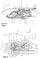
- La
figure 1 représente une coupe axiale d'un module de soufflante de l'art antérieur ; - La
figure 2 représente schématiquement suivant une coupe axiale un premier mode de réalisation d'un module de soufflante suivant l'invention ; et - La
figure 3 illustre de manière schématique suivant une coupe axiale un deuxième mode de réalisation d'un module de soufflante selon l'invention. - Sur la
figure 1 est représenté un module de soufflante d'une turbomachine destinée à être montée sur un aéronef. Cette turbomachine est ici une turbomachine double flux qui s'étend suivant un axe longitudinal X. Les références numériques correspondantes des éléments de cette turbomachine décrits précédemment sont conservées dans la suite dans la description. - En référence à la
figure 2 , la turbomachine double flux comprend de manière générale une nacelle externe (non représentée) enveloppant un générateur de gaz (non représenté) en amont duquel est montée une soufflante 2. Dans la présente invention, et de manière générale, les termes « amont » et « aval » sont définis par rapport à la circulation des gaz dans la turbomachine qui est sensiblement parallèle à l'axe longitudinal X. De même, les termes « interne », « externe », « au-dessus », « en-dessous » et « radial » sont définis par rapport à l'axe radial Y perpendiculaire à l'axe longitudinal X et au regard de l'éloignement par rapport à l'axe longitudinal X. Le générateur de gaz comprend par exemple, d'amont en aval, un compresseur basse pression, un compresseur haute pression, une chambre de combustion, une turbine haute pression et une turbine basse pression. - La soufflante 2 est ici carénée par un carter de soufflante (non représenté) solidaire de la nacelle. La soufflante 2 comprime l'air entrant dans la turbomachine qui se divise en un flux chaud ou flux primaire circulant dans une veine primaire 3 annulaire laquelle traverse le générateur de gaz et un flux froid ou flux secondaire circulant dans une veine secondaire 5 annulaire autour du générateur de gaz. En particulier, la veine primaire 3 et la veine secondaire 5 sont séparées par un carter inter-veine 6 annulaire entourant le générateur de gaz. Le carter inter-veine 6 comprend une paroi radialement interne 7 qui délimite avec une surface annulaire externe 8 d'un carter interne 9, la veine primaire 3. Le carter inter-veine 6 comprend également une paroi radialement externe 12 délimitant avec une surface annulaire interne (non représentée) de la nacelle la veine secondaire 5.
- Le module de soufflante 1 comprend un rotor de soufflante 13 traversé par un arbre de rotor 10 de soufflante qui est centré sur l'axe longitudinal X. Le rotor de soufflante 13 est enveloppé par un cône d'entrée 17 qui est agencé en amont du carter interne 9. Le carter interne 9 est fixe par rapport au rotor de soufflante 13. L'arbre de rotor 10 est entraîné en rotation par un arbre de puissance 30 de la turbomachine via un mécanisme de transmission de puissance 15 pour réduire la vitesse de rotation de la soufflante 2. Cet arbre de puissance 30 est un arbre de turbine basse pression qui relie le compresseur basse pression et la turbine basse pression pour former un corps basse pression. De même, un arbre haute pression (non représenté) relie le compresseur haute pression et la turbine haute pression pour former un corps haute pression. De manière alternative, l'arbre de puissance est un arbre de turbine de puissance indépendant du générateur de gaz. Le mécanisme de transmission de puissance 15 permet l'agencement d'une soufflante avec un diamètre important, lequel engendre une augmentation du taux de dilution. Dans le présent exemple, le taux de dilution de la soufflante est supérieur à 10. De préférence, le taux de dilution est compris entre 15 et 20.
- Le rotor de soufflante 13 porte également une série de pales 16 à calage variable. Ces pales 16 s'étendent radialement vers l'extérieur et sont délimitées par le carter de soufflante. Caque pale 16 de soufflante présente un bord d'attaque 19, amont et un bord de fuite 20, aval opposées axialement (suivant l'axe longitudinal X). Le rotor 13 comprend également un anneau de support 21 des pales 16 centré sur l'axe longitudinal X et pourvu de logements cylindriques 29 radiaux régulièrement répartis sur sa périphérie. Les pales 16 de soufflante comprennent chacune un pied 18 reçu pivotant suivant un axe de pivotement A parallèle à l'axe radial Y dans un des logements cylindriques 29. En particulier, chaque pied 18 de pale se présente sous la forme d'une attache en forme de bulbe lequel est solidaire d'un pivot 24 qui est monté dans le logement cylindrique 29. Chaque pied 18 pivote dans un logement cylindrique 29 au moyen de paliers 25 à roulements. Dans le présent exemple, deux paliers à roulement sont montés dans le logement cylindrique 2. Ces paliers sont montés l'un au-dessus de l'autre suivant l'axe radial. Les éléments roulants de ces deux paliers 25 comprennent respectivement des rouleaux 26 et des billes 27. Les rouleaux 26 sont disposés radialement au-dessus des billes 27. Comme cela est visible sur la
figure 1 , les pieds 18 des pales sont recouverts par une enveloppe annulaire 31 externe qui est centrée sur l'axe longitudinal X et qui présente une section sensiblement circulaire. Cette enveloppe externe 31 prolonge vers l'aval le cône d'entrée 17 de la soufflante et assure une continuité aérodynamique avec le cône 17. - Le module de soufflante 1 comporte un système de changement de calage 22 ou de pas des pales de la soufflante 2 permettant de faire varier le calage ou le pas des pales autour de leurs axes de pivotement A radiaux de sorte qu'elles puissent avoir des positions angulaires différentes selon les conditions de fonctionnement de la turbomachine et les phases de vol concernées. Pour cela, le système de changement de calage 22 comprend des moyens de liaison 34 reliés aux pales 16 de soufflante et un moyen de commande 23 agissant sur les moyens de liaison 34. Le système de changement de calage 22 comprend encore un module de transfert de charge 32 équipé d'un palier de transfert de charge 28 connu sous l'acronyme anglais « LTB » pour « Load Transferr Bearing ». Ce palier de transfert de charge 28 est installé entre les moyens de liaison 34 et le moyen de commande 23 de manière à assurer la transmission des efforts du moyen de commande 23 aux moyens de liaison 34.
- Le moyen de commande 23 comprend un actionneur annulaire linéaire d'axe coaxial à l'axe longitudinal X. L'actionneur linéaire comprend un corps fixe 35 et un corps mobile 36 en translation par rapport au corps fixe 35 le long de l'axe longitudinal X. De préférence, mais non limitativement, l'actionneur est hydraulique. Le déplacement du corps mobile 36 suivant l'axe longitudinal entraîne le mouvement des moyens de liaison 34, via le module de transfert de charge 32, de telle manière que celui-ci engendre le pivotement des pales 16 de soufflante autour de l'axe de pivotement A et ainsi le calage des pales 16. Le palier de transfert de charge 28 est un palier à roulement comprenant une bague interne solidaire d'une virole annulaire interne 37 et une bague externe solidaire d'une virole annulaire externe 38. La virole annulaire interne 37 est solidaire du corps mobile 36 tandis que la virole annulaire externe 38 est solidaire des moyens de liaison 34. La virole interne annulaire 37 comprend une première bride annulaire radiale 45 qui est fixée sur une deuxième bride annulaire radiale 46 portée par le corps mobile 36. La deuxième bride annulaire radiale 46 est située plus précisément à une extrémité amont 47a du corps mobile 36. Le diamètre externe de la virole externe 37 est sensiblement identique à celui du corps mobile 36. Le roulement du palier de transfert de charge 28 comprend des éléments roulants 39 qui sont guidés dans des pistes formées dans les bagues interne et externe. Les éléments roulants 39 sont ici formés par deux rangées de billes lesquelles peuvent être du type à contact oblique orientés en sens opposés de manière à optimiser la transmission des efforts axiaux.
- Sur l'exemple illustré de la
figure 2 , les moyens de liaison 34 comprennent pour chaque pale 16 une articulation sphérique 40 et un doigt 41 coopérant avec cette articulation sphérique 40. Plus précisément, le doigt 41 s'étend sensiblement radialement depuis un maneton 42 qui est prévu transversalement à l'extrémité libre du pivot 24 de chaque pied 18 de pale 16. Chaque articulation sphérique 40 est agencée dans un anneau (non représenté) qui est porté par la virole annulaire externe 38 du module de transfert de charge 32. L'articulation sphérique 40 comprend une sphère définissant une rotule à contact radial. La sphère présente un trou la traversant de part et d'autre suivant un axe B lequel est parallèle à l'axe radial. L'anneau, centré sur l'axe longitudinal X, comprend une pluralité d'évidements répartis sur sa périphérie. Chaque évidement enferme une sphère. Chacun des doigts 41 traverse le trou d'une sphère suivant un axe B sensiblement parallèle à l'axe radial Y. Les doigts 41 sont montés libres en rotation et en translation dans le trou de la sphère correspondante selon l'axe B. L'axe B est décalé par rapport à l'axe A de rotation de la pale 16. De manière alternative, le maneton 42 comprend un pion s'étendant dans une direction sensiblement opposée au doigt 41 et couplé en rotation, par exemple par des cannelures, avec le pivot de la pale correspondante. Le maneton 42 permet de démultiplier l'effort nécessaire pour régler le calage de la pale correspondante. - Le palier de transfert de charge 28 transforme le mouvement en translation du corps mobile 36 en un mouvement de translation et de rotation du doigt 41 relié au pivot 24 des pieds des pales 16 de la soufflante 2. De la sorte, toutes les pales 16 pivotent simultanément de manière à adopter au moins deux positions dites d'inversion de poussée et de mise en drapeau.
- Plus précisément, le corps fixe 35 s'étend suivant l'axe longitudinal. Celui-ci comprend une paroi 44 radiale délimitant ici deux chambres 36a, 36b à volume variable dans le corps mobile 36 et qui sont opposées axialement. Les chambres 36a, 36b sont destinées à recevoir un fluide, par exemple hydraulique sous pression, d'une source d'alimentation fluidique de sorte que le corps mobile 36 occupe au moins deux positions. Ces positions correspondent respectivement à la position d'inversion de poussée connue en anglais sous le terme « reverse » et à la position de mise en drapeau des pales de soufflante. En particulier, dans la position d'inversion de poussée les pales de la soufflante participent au freinage de l'aéronef, à la manière des inverseurs de poussée usuels. Dans la position de mise en drapeau, les pales 16 sont alors effacées au mieux par rapport à la direction d'avance de l'aéronef, par exemple en cas de panne de la turbomachine, ce qui permet de limiter la traînée. Dans cette dernière position, l'angle de calage des pales est positif, et est généralement de l'ordre de 90°.
- Le mécanisme de transmission de puissance 15 comprend un réducteur de vitesse 50 formé d'un train d'engrenage. De préférence le train d'engrenage est épicycloïdal. En particulier, le réducteur de vitesse 50 comprend un planétaire 51, des satellites 52, un porte-satellites 53 et une couronne extérieure 54. Dans le présent exemple, le planétaire 51 est centré sur l'axe longitudinal X et est solidaire en rotation avec l'arbre de puissance 30 suivant l'axe longitudinal X. Les satellites 52 sont portés par le porte-satellites 53 et tournent chacun autour d'un axe sensiblement parallèle à l'axe longitudinal X. Chacun des satellites 52 engrène avec le planétaire 51 et la couronne extérieure 54. Cette dernière est couplée avec l'arbre de rotor 10 de la soufflante et est solidaire en rotation avec l'arbre de rotor suivant l'axe longitudinal X.
- En d'autres termes, le planétaire 51 constitue l'entrée du réducteur de vitesse 50 et la couronne extérieure 54 constitue la sortie du réducteur de vitesse 50. Le porte-satellites 53 est fixe par rapport à la couronne extérieure 54 et au planétaire 51. Comme cela est visible sur la
figure 2 , le porte-satellites 53 est relié rigidement à une platine de stator 55 du carter fixe 4. Cette dernière est elle-même rigidement connectée au carter interne fixe 9 de la turbomachine. De manière avantageuse, mais non limitativement, le rapport de réduction du réducteur de vitesse est compris entre 3 et 4. - L'arbre de rotor 10 de la soufflante entraîne l'anneau de support 21 des pales 16. Pour cela, l'arbre de rotor 10 comprend une collerette 33 s'étendant sensiblement radialement et qui est solidarisé à l'anneau de support 21. Ici, la collerette 33 s'étend vers l'intérieur de la turbomachine, soit vers l'axe longitudinal X.
- Dans le présent exemple, le système de changement de calage 22 est situé radialement au moins en partie à l'intérieur de l'arbre de rotor 10 de la soufflante 2. En particulier, le moyen de commande 23 avec le corps mobile 36 et le corps fixe 35 s'étendent axialement au moins en partie à l'intérieur de l'arbre de rotor 10 par rapport à l'axe radial ce qui permet de réduire l'encombrement radial. Le corps fixe 35 comprend une première extrémité amont 43a et une deuxième extrémité aval 43b opposées axialement. La deuxième extrémité aval 43b est localisée à l'intérieur de l'arbre de rotor 10 tandis que l'extrémité amont 43a est à l'extérieur de l'arbre de rotor 10. Ici, l'arbre de rotor 10 présente une longueur axiale inférieure à celle du corps fixe
- Comme cela est également illustré schématiquement sur la
figure 2 , l'arbre de rotor 10 comprend une souplesse 10a entre la couronne extérieure 54 et l'arbre de rotor 10 de la soufflante. Une telle souplesse permet d'éviter à la couronne extérieure 54 de subir les déformations et mouvements du rotor 10. Le réducteur de vitesse 50 se trouve donc isolé des mouvements dus à d'éventuels balourds du module de soufflante. - Selon le mode de réalisation illustré, le porte-satellites 53 comprend une virole annulaire 56 fixe sur lequel est monté le corps fixe 35 du moyen de commande 23, ici l'actionneur. Plus précisément, cette virole annulaire 56 se prolonge vers l'amont du réducteur de vitesse 50 suivant l'axe longitudinal X. La virole annulaire 56 est centrée sur l'axe longitudinal X. Dans le présent exemple, la virole annulaire 56 comprend une jupe annulaire 57 s'étendant sensiblement radialement vers l'axe longitudinal X (vers l'intérieur de la turbomachine). Le corps fixe 35 est solidarisé à la jupe annulaire 57 au niveau de sa deuxième extrémité aval 43b. La jupe annulaire 57 est disposée en amont du réducteur de vitesse 50. De manière alternative, le corps fixe 35 comprend cette jupe annulaire 57 venant se fixer sur la virole annulaire 56. Un palier interne 58 est agencé entre la virole annulaire 56 du porte-satellites 53 et l'arbre de rotor 10 de soufflante de manière à reprendre l'effort de contre poussée de l'actionneur linéaire. L'effort de contre poussée est repris par les paliers 25 qui sont installés dans les logements cylindriques 29 de l'anneau de support 21. Le palier interne 58 est un palier à roulement, centré sur l'axe longitudinal X. Ce palier interne 58 comprend en particulier une bague interne (non représentée) portée par la virole annulaire 56 et une bague externe (non représentée) portée par l'arbre de rotor 10 de soufflante. En particulier, la bague externe est rotative (du fait que celle-ci est montée sur l'arbre de rotor qui tourne) et la bague interne est fixe (du fait que celle-ci est montée sur la virole annulaire du porte-satellites qui est fixe). Le palier interne 58 est situé en amont du réducteur de vitesse 50. Les bagues interne et externe définissent une piste de roulement pour des éléments roulants, ici des billes. Ces billes sont en contact radial avec les bagues interne et externe du palier interne 58. Ce dernier est ainsi apte à supporter des charges radiales et axiales. Dans cet exemple, la jupe annulaire 57 est localisée axialement en aval du palier interne 58. Un premier palier 59 et un deuxième palier 60 (pouvant être qualifiés de paliers de soufflante car ceux-ci supportent l'arbre de rotor 10) sont également disposés entre l'arbre de rotor 10 de soufflante et une couronne de support 61 fixe, centré sur l'axe longitudinal X, et solidaire du carter fixe 4. Un de ces premier et deuxième paliers 59, 60 permet de réaliser un arrêt axial de l'arbre de rotor afin de transmettre la force propulsive dégagée par la soufflante 2 aux carters et aux suspensions de la turbomachine et enfin à l'aéronef. Les premier et deuxième paliers 59, 60 comprennent chacun une bague interne (non représentée) qui est portée par l'arbre de rotor 10 de soufflante et une deuxième bague (non représentée) qui est portée par la couronne de support 61. Les éléments roulants guidés entre les bagues interne et externe du premier palier 59 sont ici des rouleaux. A l'inverse, les éléments roulant guidés entre les bagues interne et externe du deuxième palier 60 sont ici des billes. Dans le présent exemple, c'est le deuxième palier 60 à billes qui permet la reprise des efforts axiaux. Le premier palier 59 est agencé en amont du deuxième palier 60. Ce dernier est agencé en amont du réducteur de vitesse 60. Le deuxième palier 60 est également situé radialement au-dessus du palier interne 58. Dans ce mode de réalisation ainsi décrit, le rapport de moyeu du module de soufflante est compris entre 0.25 et 0.35.
- Sur la
figure 3 est illustré un deuxième mode de réalisation d'un module de soufflante selon l'invention. Les éléments décrits précédemment et identiques dans la suite de la présente description portent les mêmes références numériques. Ce mode de réalisation diffère du précédent mode de réalisation d'une part, par les moyens de liaison 34 et d'autre part, par l'agencement des différents paliers au sein du module. Les moyens de liaison 34 comprennent ici un ensemble de premières biellettes 61 articulées qui sont réparties régulièrement autour de l'actionneur. Il y a autant de premières biellettes que de pales 16. Chacune des premières biellettes 61 est reliée, d'une part à un maneton 42 d'un pied 18 de pale, et d'autre part à la virole externe 38 du module de transfert de charge 32. Les premières biellettes 61 comprennent chacune une première extrémité 62 qui est articulée suivant un axe C dans une première chape 64 de la virole externe 38 du module de transfert de charge 32. Cet axe C est sensiblement parallèle à l'axe radial Y. Les premières biellettes 61 comprennent également une deuxième extrémité 63, opposée à la première extrémité 62, qui est articulée suivant un axe D, sensiblement parallèle à l'axe Y, dans une fourchette 65 portée par le maneton 42 du pied de pale. Ces premières biellettes 61 permettent de décaler axialement le module de transfert de charge 32 par rapport à l'actionneur linéaire ce qui permet de réduire l'encombrement radial. A cet effet, la virole interne 37 du module de transfert de charge 32 comprend une flasque 66 qui est fixée sur l'extrémité amont 47a du corps mobile 36 de l'actionneur linéaire. Cette flasque 66 présente une paroi sensiblement tronconique s'évasant vers l'amont (depuis l'extrémité amont 47a du corps mobile 36) de sorte à décaler axialement et radialement vers l'extérieur le module de transfert de charge 32. - Comme nous pouvons le voir sur la
figure 3 , au moins un organe de liaison 67 relie la virole externe 38 du module de transfert de charge 32 au rotor de soufflante. Le palier de transfert de charge 28 du module de transfert de charge 32 comprend une bague interne 28a solidaire de la virole annulaire interne 37 et une bague externe 28b solidaire de la virole annulaire externe 38. De manière avantageuse, mais non limitativement, l'organe de liaison 67 comprend deux deuxièmes biellettes 68 opposées radialement. Chaque deuxième biellette 68 présente une première extrémité qui est articulée suivant un axe E à une chape d'une patte 69 bridée sur le rotor de soufflante. Une deuxième extrémité de chaque deuxième biellette 68 est articulée suivant un axe F dans une deuxième chape 70 solidaire de la virole externe 38. Cette deuxième chape 70 est opposée sensiblement axialement à la première chape 64 où sont reliées les premières biellettes 61. Les axes E, F sont sensiblement parallèles à l'axe radial Y. - Dans cet exemple de réalisation, un premier et un deuxième paliers internes 71, 72 sont disposés entre la virole annulaire 56 et l'arbre de rotor 10 de la soufflante. Comme pour le seul palier interne 58 du mode de réalisation précédente entre la virole annulaire 56 et l'arbre de rotor 10, chaque premier et deuxième palier interne 71, 72 comprend une bague interne 71a, 72a portée par la virole annulaire 56 et une bague externe 71b, 72b, portée par l'arbre de rotor 10 de soufflante. Les bagues externes 71b, 72b sont rotatives car ces dernières sont montées sur l'arbre de rotor 10. Les bagues internes 71a, 72b sont fixes car celles-ci sont montées sur la virole annulaire 56 du porte-satellites qui est fixe. Les éléments roulants du premier palier interne sont des rouleaux tandis que les éléments roulants du deuxième palier interne 72 sont des billes. Le deuxième palier interne 72 est agencé en amont du premier palier interne 71. De même, le deuxième palier interne 72 présente un diamètre extérieur qui est supérieur au diamètre extérieur du premier palier interne 71. La jupe annulaire 57 s'étend axialement entre le premier et le deuxième paliers internes 71, 72. S'agissant des premier et deuxième paliers agencés 59, 60 entre la couronne de support 61 et l'arbre de rotor 10, le diamètre du deuxième palier 60 est supérieur à celui du premier palier 59.
- Des paliers 25 entre l'anneau de support 21 annulaire fixe, et chaque pale sont agencés de manière sensiblement identique que ceux du premier mode de réalisation. En particulier, les paliers 25 sont également agencés dans le logement cylindrique 29 pour permettre la rotation de chaque pied 18. Ici, les paliers 25 sont également au nombre de deux. Les éléments roulants de ces paliers 25 comprennent des billes. Le diamètre extérieur du palier situé radialement à l'intérieur de chacun des logements cylindrique 29 est supérieur au diamètre extérieur du palier situé radialement au-dessus.
- De même, dans ce mode de réalisation, le rapport de moyeu du module de soufflante est compris entre 0.25 et 0.35.
Claims (11)
- Module de soufflante (1) à pales (16) à calage variable pour un ensemble propulsif d'axe longitudinal, ledit module de soufflante (1) comprenant :- un rotor (13) comprenant un arbre de rotor (10) suivant l'axe longitudinal X et portant les pales (16) de la soufflante (2),- un système de changement du calage des pales (22) comprenant des moyens de liaison (34) reliés aux pales (16) de la soufflante (2) et un moyen de commande (23) agissant sur les moyens de liaison (34), le moyen de commande (23) comportant un corps fixe (35) et un corps mobile (36) en translation selon l'axe longitudinal X par rapport audit corps fixe (35),- un palier de transfert de charge (28) agencé entre les moyens de liaison (34) et le moyen de commande (23),- un arbre de puissance (30) entraînant l'arbre de rotor (10) via un réducteur de vitesse (50) à train épicycloïdal, le réducteur de vitesse (50) comprenant un planétaire (51) relié à l'arbre de puissance (30) et un porte-satellites (53) comprenant une virole annulaire (56) fixe solidaire d'un carter fixe (4), le corps fixe (35) du moyen de commande (23) étant monté sur ladite virole annulaire (56), et,- au moins un palier interne (58 ; 71, 72) agencé entre la virole annulaire (56) fixe du porte-satellites (53) et l'arbre de rotor (10) de la soufflante,caractérisé en ce qu'un premier et un deuxième paliers (59, 60) sont montés entre une couronne de support (61) solidaire du carter fixe (4) et l'arbre de rotor (10) de la soufflante.
- Module de soufflante (1) selon la revendication précédente, caractérisé en ce que le moyen de commande (23) est installé radialement au moins en partie à l'intérieur de l'arbre de rotor (10) de la soufflante, en particulier selon un axe de pivotement des pales.
- Module de soufflante (1) selon l'une quelconque des revendications précédentes, caractérisé en ce que le palier de transfert de charge (28) est monté sur le corps mobile (36) et coopère avec les moyens de liaison (34).
- Module de soufflante (1) selon l'une quelconque des revendications précédentes, caractérisé en ce que le réducteur de vitesse (50) comprend une couronne extérieure (54) couplée à l'arbre de rotor (10) de la soufflante.
- Module de soufflante (1) selon l'une quelconque des revendications précédentes, caractérisé en ce que le palier de transfert de charge (28) comprend une bague interne (28a), une bague externe (28b) et un roulement à deux rangées de billes (39) montées entre la bague interne (28a) et la bague externe (28b), la bague interne (28a) étant reliée à une virole interne (37) solidaire du corps mobile (36) et la bague externe étant reliée à une virole externe (38) connectée aux moyens de liaison (34).
- Module de soufflante (1) selon la revendication précédente, caractérisé en ce que les moyens de liaison (34) comprennent des biellettes (61) avec chacune une première extrémité (62) articulée avec une chape (64) de la virole externe (38) et une deuxième extrémité (63) articulée avec un maneton (42) du pied (18) de pale.
- Module de soufflante (1) selon la revendication 5, caractérisé en ce que les moyens de liaison (34) comprennent des articulations sphériques (40) agencées chacune dans un évidement d'un anneau solidaire de la virole externe (38) du palier de transfert de charge (28) et des doigts (41) reliés chacun à une des articulations sphériques (41), chaque doigt (41) étant solidaire d'un maneton (42) du pied (18) de pale.
- Module de soufflante (1) selon la revendication 6, caractérisé en ce que le module de soufflante comprend au moins un organe de liaison (67) reliant la virole externe (38) au rotor de soufflante (13).
- Module de soufflante (1) selon l'une quelconque des revendications précédentes, caractérisé en ce que le moyen de commande (23) comprend un actionneur annulaire linéaire d'axe coaxial à l'axe longitudinal X, l'actionneur linéaire comprenant le corps fixe (35) et le corps mobile (36) en translation par rapport au corps fixe (35) le long de l'axe longitudinal X.
- Module de soufflante (1) selon l'une quelconque des revendications précédentes, caractérisé en ce que le corps fixe (35) comprend une paroi (44) radiale délimitant deux chambres (36a, 36b) à volume variable dans le corps mobile (36) et qui sont opposées axialement, les chambres étant destinées à recevoir un fluide, par exemple hydraulique sous pression, d'une source d'alimentation fluidique de sorte que le corps mobile (36) occupe au moins deux positions.
- Module de soufflante (1) selon l'une quelconque des revendications précédentes, caractérisé en ce que le moyen de commande (23) avec le corps mobile (36) et le corps fixe (35) s'étendent axialement au moins en partie à l'intérieur de l'arbre de rotor (10) par rapport à l'axe radial, le corps fixe (35) comprenant une première extrémité amont (43a) et une deuxième extrémité aval (43b) opposées axialement, l'extrémité aval (43b) étant localisée à l'intérieur de l'arbre de rotor (10) et l'extrémité amont (43a) étant à l'extérieur de l'arbre de rotor (10).
Applications Claiming Priority (1)
| Application Number | Priority Date | Filing Date | Title |
|---|---|---|---|
| FR1860023A FR3087857B1 (fr) | 2018-10-30 | 2018-10-30 | Module de soufflante a pales a calage variable |
Publications (2)
| Publication Number | Publication Date |
|---|---|
| EP3647546A1 EP3647546A1 (fr) | 2020-05-06 |
| EP3647546B1 true EP3647546B1 (fr) | 2024-11-27 |
Family
ID=65444153
Family Applications (1)
| Application Number | Title | Priority Date | Filing Date |
|---|---|---|---|
| EP19205722.2A Active EP3647546B1 (fr) | 2018-10-30 | 2019-10-28 | Module de soufflante a pales a calage variable |
Country Status (4)
| Country | Link |
|---|---|
| US (1) | US11506066B2 (fr) |
| EP (1) | EP3647546B1 (fr) |
| CN (1) | CN111120010B (fr) |
| FR (1) | FR3087857B1 (fr) |
Families Citing this family (5)
| Publication number | Priority date | Publication date | Assignee | Title |
|---|---|---|---|---|
| BE1025642B1 (fr) * | 2017-10-16 | 2019-05-15 | Safran Aero Boosters S.A. | Carter de compresseur avec reservoir d'huile pour turbomachine |
| FR3101664B1 (fr) * | 2019-10-02 | 2021-09-03 | Safran Aircraft Engines | Système de commande de calage cyclique de pales |
| FR3120913B1 (fr) * | 2021-03-16 | 2023-02-24 | Safran Aircraft Engines | Module de soufflante equipe d’un dispositif de transfert d’huile |
| FR3123884B1 (fr) | 2021-06-15 | 2024-05-03 | Safran Aircraft Engines | Systeme de changement de pas des pales d’une helice d’une turbomachine |
| FR3126019B1 (fr) | 2021-08-04 | 2023-08-11 | Safran Aircraft Engines | Module de soufflante a pales a calage variable |
Family Cites Families (6)
| Publication number | Priority date | Publication date | Assignee | Title |
|---|---|---|---|---|
| US3922852A (en) * | 1973-10-17 | 1975-12-02 | Gen Electric | Variable pitch fan for gas turbine engine |
| US4704862A (en) * | 1985-05-29 | 1987-11-10 | United Technologies Corporation | Ducted prop engine |
| GB0904913D0 (en) * | 2009-03-24 | 2009-05-06 | Rolls Royce Plc | A mechanical arrangement |
| US8869504B1 (en) * | 2013-11-22 | 2014-10-28 | United Technologies Corporation | Geared turbofan engine gearbox arrangement |
| PL226824B1 (pl) * | 2015-09-07 | 2017-09-29 | Gen Electric | Układ isposób regulacji skoku smigła |
| US10196980B2 (en) * | 2016-02-08 | 2019-02-05 | General Electric Company | Bearing outer race retention during high load events |
-
2018
- 2018-10-30 FR FR1860023A patent/FR3087857B1/fr active Active
-
2019
- 2019-10-28 EP EP19205722.2A patent/EP3647546B1/fr active Active
- 2019-10-28 US US16/666,158 patent/US11506066B2/en active Active
- 2019-10-29 CN CN201911038134.1A patent/CN111120010B/zh active Active
Also Published As
| Publication number | Publication date |
|---|---|
| FR3087857B1 (fr) | 2021-02-12 |
| US11506066B2 (en) | 2022-11-22 |
| US20200131917A1 (en) | 2020-04-30 |
| EP3647546A1 (fr) | 2020-05-06 |
| CN111120010B (zh) | 2024-02-23 |
| FR3087857A1 (fr) | 2020-05-01 |
| CN111120010A (zh) | 2020-05-08 |
Similar Documents
| Publication | Publication Date | Title |
|---|---|---|
| EP3647546B1 (fr) | Module de soufflante a pales a calage variable | |
| EP2763893B1 (fr) | Turbomachine a helice(s) pour aeronef avec systeme pour changer le pas de l'helice | |
| EP3864297B1 (fr) | Module de soufflante a pales a calage variable | |
| EP4107398A1 (fr) | Module de turbomachine equipe de systeme de changement de pas des pales d aubes de stator | |
| WO2022069835A1 (fr) | Module de turbomachine equipe d'une helice et d'aubes de stator deportees | |
| FR3055000A1 (fr) | Module de changement de pas pour turbomachine et turbomachine correspondante | |
| FR3104642A1 (fr) | Système propulsif aéronautique à faible débit de fuite et rendement propulsif amélioré | |
| EP4073371B1 (fr) | Système propulsif aéronautique à faible débit de fuite et rendement propulsif amélioré | |
| EP4380858B1 (fr) | Module de soufflante a pales a calage variable | |
| FR2831934A1 (fr) | Boite de transmission basculante avec dispositif de rattrapage de jeu selon l'axe de basculement | |
| FR3021296A1 (fr) | Ensemble de propulsion a doublet d'helices pour aeronef | |
| FR3126018A1 (fr) | Systeme de changement de pas des pales d’une soufflante d’un ensemble propulsif | |
| FR3059364A1 (fr) | Systeme de suspension d'un premier element annulaire dans un deuxieme element annulaire de turbomachine et turbomachine correspondante | |
| FR3072714A1 (fr) | Tube de transfert d'huile pour un systeme de commande de regulation du pas d'une helice de turbomachine | |
| FR3057909A1 (fr) | Turbomachine d'aeronef comprenant une zone fusible agencee sur un arbre pivotant | |
| EP4073356B1 (fr) | Turbomachine à turbine contrarotative pour un aéronef | |
| EP3999719B1 (fr) | Module de turbomachine équipé de systeme de changement de pas des pales d'une hélice et d'un dispositif de mise en drapeau des pales | |
| FR3130746A1 (fr) | Module de soufflante a pales a calage variable | |
| FR3126017A1 (fr) | Module de soufflante a pales a calage variable | |
| EP4727843A1 (fr) | Ensemble propulsif pour aéronef pourvu d'une hélice et d'un dispositif de calage cyclique des aubes de l'hélice et procédé de régulation du calage cyclique des aubes de l'hélice | |
| EP4448382A1 (fr) | Ensemble hydraulique pour un moteur d'aeronef | |
| FR3125505A1 (fr) | Systeme de changement de pas des pales d’une helice d’une turbomachine |
Legal Events
| Date | Code | Title | Description |
|---|---|---|---|
| PUAI | Public reference made under article 153(3) epc to a published international application that has entered the european phase |
Free format text: ORIGINAL CODE: 0009012 |
|
| STAA | Information on the status of an ep patent application or granted ep patent |
Free format text: STATUS: REQUEST FOR EXAMINATION WAS MADE |
|
| 17P | Request for examination filed |
Effective date: 20191028 |
|
| AK | Designated contracting states |
Kind code of ref document: A1 Designated state(s): AL AT BE BG CH CY CZ DE DK EE ES FI FR GB GR HR HU IE IS IT LI LT LU LV MC MK MT NL NO PL PT RO RS SE SI SK SM TR |
|
| STAA | Information on the status of an ep patent application or granted ep patent |
Free format text: STATUS: EXAMINATION IS IN PROGRESS |
|
| 17Q | First examination report despatched |
Effective date: 20220118 |
|
| GRAP | Despatch of communication of intention to grant a patent |
Free format text: ORIGINAL CODE: EPIDOSNIGR1 |
|
| STAA | Information on the status of an ep patent application or granted ep patent |
Free format text: STATUS: GRANT OF PATENT IS INTENDED |
|
| INTG | Intention to grant announced |
Effective date: 20230901 |
|
| GRAJ | Information related to disapproval of communication of intention to grant by the applicant or resumption of examination proceedings by the epo deleted |
Free format text: ORIGINAL CODE: EPIDOSDIGR1 |
|
| STAA | Information on the status of an ep patent application or granted ep patent |
Free format text: STATUS: EXAMINATION IS IN PROGRESS |
|
| GRAP | Despatch of communication of intention to grant a patent |
Free format text: ORIGINAL CODE: EPIDOSNIGR1 |
|
| STAA | Information on the status of an ep patent application or granted ep patent |
Free format text: STATUS: GRANT OF PATENT IS INTENDED |
|
| INTC | Intention to grant announced (deleted) | ||
| INTG | Intention to grant announced |
Effective date: 20240201 |
|
| GRAJ | Information related to disapproval of communication of intention to grant by the applicant or resumption of examination proceedings by the epo deleted |
Free format text: ORIGINAL CODE: EPIDOSDIGR1 |
|
| STAA | Information on the status of an ep patent application or granted ep patent |
Free format text: STATUS: EXAMINATION IS IN PROGRESS |
|
| INTC | Intention to grant announced (deleted) | ||
| GRAP | Despatch of communication of intention to grant a patent |
Free format text: ORIGINAL CODE: EPIDOSNIGR1 |
|
| STAA | Information on the status of an ep patent application or granted ep patent |
Free format text: STATUS: GRANT OF PATENT IS INTENDED |
|
| INTG | Intention to grant announced |
Effective date: 20240715 |
|
| GRAS | Grant fee paid |
Free format text: ORIGINAL CODE: EPIDOSNIGR3 |
|
| GRAA | (expected) grant |
Free format text: ORIGINAL CODE: 0009210 |
|
| STAA | Information on the status of an ep patent application or granted ep patent |
Free format text: STATUS: THE PATENT HAS BEEN GRANTED |
|
| AK | Designated contracting states |
Kind code of ref document: B1 Designated state(s): AL AT BE BG CH CY CZ DE DK EE ES FI FR GB GR HR HU IE IS IT LI LT LU LV MC MK MT NL NO PL PT RO RS SE SI SK SM TR |
|
| REG | Reference to a national code |
Ref country code: GB Ref legal event code: FG4D Free format text: NOT ENGLISH |
|
| REG | Reference to a national code |
Ref country code: CH Ref legal event code: EP |
|
| REG | Reference to a national code |
Ref country code: DE Ref legal event code: R096 Ref document number: 602019062514 Country of ref document: DE |
|
| REG | Reference to a national code |
Ref country code: IE Ref legal event code: FG4D Free format text: LANGUAGE OF EP DOCUMENT: FRENCH |
|
| REG | Reference to a national code |
Ref country code: LT Ref legal event code: MG9D |
|
| REG | Reference to a national code |
Ref country code: NL Ref legal event code: MP Effective date: 20241127 |
|
| PG25 | Lapsed in a contracting state [announced via postgrant information from national office to epo] |
Ref country code: IS Free format text: LAPSE BECAUSE OF FAILURE TO SUBMIT A TRANSLATION OF THE DESCRIPTION OR TO PAY THE FEE WITHIN THE PRESCRIBED TIME-LIMIT Effective date: 20250327 Ref country code: PT Free format text: LAPSE BECAUSE OF FAILURE TO SUBMIT A TRANSLATION OF THE DESCRIPTION OR TO PAY THE FEE WITHIN THE PRESCRIBED TIME-LIMIT Effective date: 20250327 Ref country code: HR Free format text: LAPSE BECAUSE OF FAILURE TO SUBMIT A TRANSLATION OF THE DESCRIPTION OR TO PAY THE FEE WITHIN THE PRESCRIBED TIME-LIMIT Effective date: 20241127 |
|
| PG25 | Lapsed in a contracting state [announced via postgrant information from national office to epo] |
Ref country code: FI Free format text: LAPSE BECAUSE OF FAILURE TO SUBMIT A TRANSLATION OF THE DESCRIPTION OR TO PAY THE FEE WITHIN THE PRESCRIBED TIME-LIMIT Effective date: 20241127 Ref country code: NL Free format text: LAPSE BECAUSE OF FAILURE TO SUBMIT A TRANSLATION OF THE DESCRIPTION OR TO PAY THE FEE WITHIN THE PRESCRIBED TIME-LIMIT Effective date: 20241127 |
|
| REG | Reference to a national code |
Ref country code: AT Ref legal event code: MK05 Ref document number: 1745883 Country of ref document: AT Kind code of ref document: T Effective date: 20241127 |
|
| PG25 | Lapsed in a contracting state [announced via postgrant information from national office to epo] |
Ref country code: BG Free format text: LAPSE BECAUSE OF FAILURE TO SUBMIT A TRANSLATION OF THE DESCRIPTION OR TO PAY THE FEE WITHIN THE PRESCRIBED TIME-LIMIT Effective date: 20241127 |
|
| PG25 | Lapsed in a contracting state [announced via postgrant information from national office to epo] |
Ref country code: ES Free format text: LAPSE BECAUSE OF FAILURE TO SUBMIT A TRANSLATION OF THE DESCRIPTION OR TO PAY THE FEE WITHIN THE PRESCRIBED TIME-LIMIT Effective date: 20241127 |
|
| PG25 | Lapsed in a contracting state [announced via postgrant information from national office to epo] |
Ref country code: NO Free format text: LAPSE BECAUSE OF FAILURE TO SUBMIT A TRANSLATION OF THE DESCRIPTION OR TO PAY THE FEE WITHIN THE PRESCRIBED TIME-LIMIT Effective date: 20250227 |
|
| PG25 | Lapsed in a contracting state [announced via postgrant information from national office to epo] |
Ref country code: LV Free format text: LAPSE BECAUSE OF FAILURE TO SUBMIT A TRANSLATION OF THE DESCRIPTION OR TO PAY THE FEE WITHIN THE PRESCRIBED TIME-LIMIT Effective date: 20241127 Ref country code: AT Free format text: LAPSE BECAUSE OF FAILURE TO SUBMIT A TRANSLATION OF THE DESCRIPTION OR TO PAY THE FEE WITHIN THE PRESCRIBED TIME-LIMIT Effective date: 20241127 Ref country code: GR Free format text: LAPSE BECAUSE OF FAILURE TO SUBMIT A TRANSLATION OF THE DESCRIPTION OR TO PAY THE FEE WITHIN THE PRESCRIBED TIME-LIMIT Effective date: 20250228 |
|
| PG25 | Lapsed in a contracting state [announced via postgrant information from national office to epo] |
Ref country code: PL Free format text: LAPSE BECAUSE OF FAILURE TO SUBMIT A TRANSLATION OF THE DESCRIPTION OR TO PAY THE FEE WITHIN THE PRESCRIBED TIME-LIMIT Effective date: 20241127 |
|
| PG25 | Lapsed in a contracting state [announced via postgrant information from national office to epo] |
Ref country code: RS Free format text: LAPSE BECAUSE OF FAILURE TO SUBMIT A TRANSLATION OF THE DESCRIPTION OR TO PAY THE FEE WITHIN THE PRESCRIBED TIME-LIMIT Effective date: 20250227 |
|
| PG25 | Lapsed in a contracting state [announced via postgrant information from national office to epo] |
Ref country code: SM Free format text: LAPSE BECAUSE OF FAILURE TO SUBMIT A TRANSLATION OF THE DESCRIPTION OR TO PAY THE FEE WITHIN THE PRESCRIBED TIME-LIMIT Effective date: 20241127 |
|
| PG25 | Lapsed in a contracting state [announced via postgrant information from national office to epo] |
Ref country code: DK Free format text: LAPSE BECAUSE OF FAILURE TO SUBMIT A TRANSLATION OF THE DESCRIPTION OR TO PAY THE FEE WITHIN THE PRESCRIBED TIME-LIMIT Effective date: 20241127 |
|
| PG25 | Lapsed in a contracting state [announced via postgrant information from national office to epo] |
Ref country code: EE Free format text: LAPSE BECAUSE OF FAILURE TO SUBMIT A TRANSLATION OF THE DESCRIPTION OR TO PAY THE FEE WITHIN THE PRESCRIBED TIME-LIMIT Effective date: 20241127 |
|
| PG25 | Lapsed in a contracting state [announced via postgrant information from national office to epo] |
Ref country code: RO Free format text: LAPSE BECAUSE OF FAILURE TO SUBMIT A TRANSLATION OF THE DESCRIPTION OR TO PAY THE FEE WITHIN THE PRESCRIBED TIME-LIMIT Effective date: 20241127 |
|
| PG25 | Lapsed in a contracting state [announced via postgrant information from national office to epo] |
Ref country code: SK Free format text: LAPSE BECAUSE OF FAILURE TO SUBMIT A TRANSLATION OF THE DESCRIPTION OR TO PAY THE FEE WITHIN THE PRESCRIBED TIME-LIMIT Effective date: 20241127 |
|
| PG25 | Lapsed in a contracting state [announced via postgrant information from national office to epo] |
Ref country code: CZ Free format text: LAPSE BECAUSE OF FAILURE TO SUBMIT A TRANSLATION OF THE DESCRIPTION OR TO PAY THE FEE WITHIN THE PRESCRIBED TIME-LIMIT Effective date: 20241127 |
|
| PG25 | Lapsed in a contracting state [announced via postgrant information from national office to epo] |
Ref country code: IT Free format text: LAPSE BECAUSE OF FAILURE TO SUBMIT A TRANSLATION OF THE DESCRIPTION OR TO PAY THE FEE WITHIN THE PRESCRIBED TIME-LIMIT Effective date: 20241127 |
|
| REG | Reference to a national code |
Ref country code: DE Ref legal event code: R097 Ref document number: 602019062514 Country of ref document: DE |
|
| PG25 | Lapsed in a contracting state [announced via postgrant information from national office to epo] |
Ref country code: SE Free format text: LAPSE BECAUSE OF FAILURE TO SUBMIT A TRANSLATION OF THE DESCRIPTION OR TO PAY THE FEE WITHIN THE PRESCRIBED TIME-LIMIT Effective date: 20241127 |
|
| PLBE | No opposition filed within time limit |
Free format text: ORIGINAL CODE: 0009261 |
|
| STAA | Information on the status of an ep patent application or granted ep patent |
Free format text: STATUS: NO OPPOSITION FILED WITHIN TIME LIMIT |
|
| 26N | No opposition filed |
Effective date: 20250828 |
|
| PGFP | Annual fee paid to national office [announced via postgrant information from national office to epo] |
Ref country code: DE Payment date: 20251020 Year of fee payment: 7 |
|
| PGFP | Annual fee paid to national office [announced via postgrant information from national office to epo] |
Ref country code: GB Payment date: 20251029 Year of fee payment: 7 |
|
| PGFP | Annual fee paid to national office [announced via postgrant information from national office to epo] |
Ref country code: FR Payment date: 20251023 Year of fee payment: 7 |