EP3647520A1 - Intrusion-safe roof window - Google Patents
Intrusion-safe roof window Download PDFInfo
- Publication number
- EP3647520A1 EP3647520A1 EP19203528.5A EP19203528A EP3647520A1 EP 3647520 A1 EP3647520 A1 EP 3647520A1 EP 19203528 A EP19203528 A EP 19203528A EP 3647520 A1 EP3647520 A1 EP 3647520A1
- Authority
- EP
- European Patent Office
- Prior art keywords
- sash
- opening
- pin
- push
- side member
- Prior art date
- Legal status (The legal status is an assumption and is not a legal conclusion. Google has not performed a legal analysis and makes no representation as to the accuracy of the status listed.)
- Granted
Links
Images




Classifications
-
- E—FIXED CONSTRUCTIONS
- E05—LOCKS; KEYS; WINDOW OR DOOR FITTINGS; SAFES
- E05F—DEVICES FOR MOVING WINGS INTO OPEN OR CLOSED POSITION; CHECKS FOR WINGS; WING FITTINGS NOT OTHERWISE PROVIDED FOR, CONCERNED WITH THE FUNCTIONING OF THE WING
- E05F15/00—Power-operated mechanisms for wings
- E05F15/60—Power-operated mechanisms for wings using electrical actuators
- E05F15/603—Power-operated mechanisms for wings using electrical actuators using rotary electromotors
- E05F15/611—Power-operated mechanisms for wings using electrical actuators using rotary electromotors for swinging wings
- E05F15/616—Power-operated mechanisms for wings using electrical actuators using rotary electromotors for swinging wings operated by push-pull mechanisms
- E05F15/619—Power-operated mechanisms for wings using electrical actuators using rotary electromotors for swinging wings operated by push-pull mechanisms using flexible or rigid rack-and-pinion arrangements
-
- E—FIXED CONSTRUCTIONS
- E05—LOCKS; KEYS; WINDOW OR DOOR FITTINGS; SAFES
- E05F—DEVICES FOR MOVING WINGS INTO OPEN OR CLOSED POSITION; CHECKS FOR WINGS; WING FITTINGS NOT OTHERWISE PROVIDED FOR, CONCERNED WITH THE FUNCTIONING OF THE WING
- E05F11/00—Man-operated mechanisms for operating wings, including those which also operate the fastening
- E05F11/02—Man-operated mechanisms for operating wings, including those which also operate the fastening for wings in general, e.g. fanlights
- E05F11/04—Man-operated mechanisms for operating wings, including those which also operate the fastening for wings in general, e.g. fanlights with cords, chains or cables
- E05F11/06—Man-operated mechanisms for operating wings, including those which also operate the fastening for wings in general, e.g. fanlights with cords, chains or cables in guide-channels
-
- E—FIXED CONSTRUCTIONS
- E05—LOCKS; KEYS; WINDOW OR DOOR FITTINGS; SAFES
- E05D—HINGES OR SUSPENSION DEVICES FOR DOORS, WINDOWS OR WINGS
- E05D15/00—Suspension arrangements for wings
- E05D15/40—Suspension arrangements for wings supported on arms movable in vertical planes
-
- E—FIXED CONSTRUCTIONS
- E05—LOCKS; KEYS; WINDOW OR DOOR FITTINGS; SAFES
- E05D—HINGES OR SUSPENSION DEVICES FOR DOORS, WINDOWS OR WINGS
- E05D7/00—Hinges or pivots of special construction
- E05D7/08—Hinges or pivots of special construction for use in suspensions comprising two spigots placed at opposite edges of the wing, especially at the top and the bottom, e.g. trunnions
-
- E—FIXED CONSTRUCTIONS
- E05—LOCKS; KEYS; WINDOW OR DOOR FITTINGS; SAFES
- E05D—HINGES OR SUSPENSION DEVICES FOR DOORS, WINDOWS OR WINGS
- E05D7/00—Hinges or pivots of special construction
- E05D7/08—Hinges or pivots of special construction for use in suspensions comprising two spigots placed at opposite edges of the wing, especially at the top and the bottom, e.g. trunnions
- E05D7/081—Hinges or pivots of special construction for use in suspensions comprising two spigots placed at opposite edges of the wing, especially at the top and the bottom, e.g. trunnions the pivot axis of the wing being situated near one edge of the wing, especially at the top and bottom, e.g. trunnions
-
- E—FIXED CONSTRUCTIONS
- E05—LOCKS; KEYS; WINDOW OR DOOR FITTINGS; SAFES
- E05D—HINGES OR SUSPENSION DEVICES FOR DOORS, WINDOWS OR WINGS
- E05D7/00—Hinges or pivots of special construction
- E05D7/08—Hinges or pivots of special construction for use in suspensions comprising two spigots placed at opposite edges of the wing, especially at the top and the bottom, e.g. trunnions
- E05D7/082—Hinges or pivots of special construction for use in suspensions comprising two spigots placed at opposite edges of the wing, especially at the top and the bottom, e.g. trunnions the pivot axis of the wing being situated at a considerable distance from the edges of the wing, e.g. for balanced wings
-
- E—FIXED CONSTRUCTIONS
- E05—LOCKS; KEYS; WINDOW OR DOOR FITTINGS; SAFES
- E05Y—INDEXING SCHEME ASSOCIATED WITH SUBCLASSES E05D AND E05F, RELATING TO CONSTRUCTION ELEMENTS, ELECTRIC CONTROL, POWER SUPPLY, POWER SIGNAL OR TRANSMISSION, USER INTERFACES, MOUNTING OR COUPLING, DETAILS, ACCESSORIES, AUXILIARY OPERATIONS NOT OTHERWISE PROVIDED FOR, APPLICATION THEREOF
- E05Y2201/00—Constructional elements; Accessories therefor
- E05Y2201/20—Brakes; Disengaging means; Holders; Stops; Valves; Accessories therefor
- E05Y2201/218—Holders
-
- E—FIXED CONSTRUCTIONS
- E05—LOCKS; KEYS; WINDOW OR DOOR FITTINGS; SAFES
- E05Y—INDEXING SCHEME ASSOCIATED WITH SUBCLASSES E05D AND E05F, RELATING TO CONSTRUCTION ELEMENTS, ELECTRIC CONTROL, POWER SUPPLY, POWER SIGNAL OR TRANSMISSION, USER INTERFACES, MOUNTING OR COUPLING, DETAILS, ACCESSORIES, AUXILIARY OPERATIONS NOT OTHERWISE PROVIDED FOR, APPLICATION THEREOF
- E05Y2201/00—Constructional elements; Accessories therefor
- E05Y2201/20—Brakes; Disengaging means; Holders; Stops; Valves; Accessories therefor
- E05Y2201/218—Holders
- E05Y2201/22—Locks
-
- E—FIXED CONSTRUCTIONS
- E05—LOCKS; KEYS; WINDOW OR DOOR FITTINGS; SAFES
- E05Y—INDEXING SCHEME ASSOCIATED WITH SUBCLASSES E05D AND E05F, RELATING TO CONSTRUCTION ELEMENTS, ELECTRIC CONTROL, POWER SUPPLY, POWER SIGNAL OR TRANSMISSION, USER INTERFACES, MOUNTING OR COUPLING, DETAILS, ACCESSORIES, AUXILIARY OPERATIONS NOT OTHERWISE PROVIDED FOR, APPLICATION THEREOF
- E05Y2201/00—Constructional elements; Accessories therefor
- E05Y2201/40—Motors; Magnets; Springs; Weights; Accessories therefor
- E05Y2201/47—Springs
-
- E—FIXED CONSTRUCTIONS
- E05—LOCKS; KEYS; WINDOW OR DOOR FITTINGS; SAFES
- E05Y—INDEXING SCHEME ASSOCIATED WITH SUBCLASSES E05D AND E05F, RELATING TO CONSTRUCTION ELEMENTS, ELECTRIC CONTROL, POWER SUPPLY, POWER SIGNAL OR TRANSMISSION, USER INTERFACES, MOUNTING OR COUPLING, DETAILS, ACCESSORIES, AUXILIARY OPERATIONS NOT OTHERWISE PROVIDED FOR, APPLICATION THEREOF
- E05Y2201/00—Constructional elements; Accessories therefor
- E05Y2201/60—Suspension or transmission members; Accessories therefor
- E05Y2201/622—Suspension or transmission members elements
- E05Y2201/624—Arms
-
- E—FIXED CONSTRUCTIONS
- E05—LOCKS; KEYS; WINDOW OR DOOR FITTINGS; SAFES
- E05Y—INDEXING SCHEME ASSOCIATED WITH SUBCLASSES E05D AND E05F, RELATING TO CONSTRUCTION ELEMENTS, ELECTRIC CONTROL, POWER SUPPLY, POWER SIGNAL OR TRANSMISSION, USER INTERFACES, MOUNTING OR COUPLING, DETAILS, ACCESSORIES, AUXILIARY OPERATIONS NOT OTHERWISE PROVIDED FOR, APPLICATION THEREOF
- E05Y2201/00—Constructional elements; Accessories therefor
- E05Y2201/60—Suspension or transmission members; Accessories therefor
- E05Y2201/622—Suspension or transmission members elements
- E05Y2201/644—Flexible elongated pulling elements
- E05Y2201/656—Chains
-
- E—FIXED CONSTRUCTIONS
- E05—LOCKS; KEYS; WINDOW OR DOOR FITTINGS; SAFES
- E05Y—INDEXING SCHEME ASSOCIATED WITH SUBCLASSES E05D AND E05F, RELATING TO CONSTRUCTION ELEMENTS, ELECTRIC CONTROL, POWER SUPPLY, POWER SIGNAL OR TRANSMISSION, USER INTERFACES, MOUNTING OR COUPLING, DETAILS, ACCESSORIES, AUXILIARY OPERATIONS NOT OTHERWISE PROVIDED FOR, APPLICATION THEREOF
- E05Y2201/00—Constructional elements; Accessories therefor
- E05Y2201/60—Suspension or transmission members; Accessories therefor
- E05Y2201/622—Suspension or transmission members elements
- E05Y2201/682—Pins
-
- E—FIXED CONSTRUCTIONS
- E05—LOCKS; KEYS; WINDOW OR DOOR FITTINGS; SAFES
- E05Y—INDEXING SCHEME ASSOCIATED WITH SUBCLASSES E05D AND E05F, RELATING TO CONSTRUCTION ELEMENTS, ELECTRIC CONTROL, POWER SUPPLY, POWER SIGNAL OR TRANSMISSION, USER INTERFACES, MOUNTING OR COUPLING, DETAILS, ACCESSORIES, AUXILIARY OPERATIONS NOT OTHERWISE PROVIDED FOR, APPLICATION THEREOF
- E05Y2201/00—Constructional elements; Accessories therefor
- E05Y2201/60—Suspension or transmission members; Accessories therefor
- E05Y2201/622—Suspension or transmission members elements
- E05Y2201/71—Toothed gearing
- E05Y2201/722—Racks
- E05Y2201/724—Flexible
-
- E—FIXED CONSTRUCTIONS
- E05—LOCKS; KEYS; WINDOW OR DOOR FITTINGS; SAFES
- E05Y—INDEXING SCHEME ASSOCIATED WITH SUBCLASSES E05D AND E05F, RELATING TO CONSTRUCTION ELEMENTS, ELECTRIC CONTROL, POWER SUPPLY, POWER SIGNAL OR TRANSMISSION, USER INTERFACES, MOUNTING OR COUPLING, DETAILS, ACCESSORIES, AUXILIARY OPERATIONS NOT OTHERWISE PROVIDED FOR, APPLICATION THEREOF
- E05Y2600/00—Mounting or coupling arrangements for elements provided for in this subclass
- E05Y2600/50—Mounting methods; Positioning
- E05Y2600/52—Toolless
-
- E—FIXED CONSTRUCTIONS
- E05—LOCKS; KEYS; WINDOW OR DOOR FITTINGS; SAFES
- E05Y—INDEXING SCHEME ASSOCIATED WITH SUBCLASSES E05D AND E05F, RELATING TO CONSTRUCTION ELEMENTS, ELECTRIC CONTROL, POWER SUPPLY, POWER SIGNAL OR TRANSMISSION, USER INTERFACES, MOUNTING OR COUPLING, DETAILS, ACCESSORIES, AUXILIARY OPERATIONS NOT OTHERWISE PROVIDED FOR, APPLICATION THEREOF
- E05Y2600/00—Mounting or coupling arrangements for elements provided for in this subclass
- E05Y2600/50—Mounting methods; Positioning
- E05Y2600/52—Toolless
- E05Y2600/528—Hooking, e.g. using bayonets; Locking
-
- E—FIXED CONSTRUCTIONS
- E05—LOCKS; KEYS; WINDOW OR DOOR FITTINGS; SAFES
- E05Y—INDEXING SCHEME ASSOCIATED WITH SUBCLASSES E05D AND E05F, RELATING TO CONSTRUCTION ELEMENTS, ELECTRIC CONTROL, POWER SUPPLY, POWER SIGNAL OR TRANSMISSION, USER INTERFACES, MOUNTING OR COUPLING, DETAILS, ACCESSORIES, AUXILIARY OPERATIONS NOT OTHERWISE PROVIDED FOR, APPLICATION THEREOF
- E05Y2600/00—Mounting or coupling arrangements for elements provided for in this subclass
- E05Y2600/50—Mounting methods; Positioning
- E05Y2600/52—Toolless
- E05Y2600/53—Snapping
-
- E—FIXED CONSTRUCTIONS
- E05—LOCKS; KEYS; WINDOW OR DOOR FITTINGS; SAFES
- E05Y—INDEXING SCHEME ASSOCIATED WITH SUBCLASSES E05D AND E05F, RELATING TO CONSTRUCTION ELEMENTS, ELECTRIC CONTROL, POWER SUPPLY, POWER SIGNAL OR TRANSMISSION, USER INTERFACES, MOUNTING OR COUPLING, DETAILS, ACCESSORIES, AUXILIARY OPERATIONS NOT OTHERWISE PROVIDED FOR, APPLICATION THEREOF
- E05Y2600/00—Mounting or coupling arrangements for elements provided for in this subclass
- E05Y2600/60—Mounting or coupling members; Accessories therefor
- E05Y2600/626—Plates or brackets
-
- E—FIXED CONSTRUCTIONS
- E05—LOCKS; KEYS; WINDOW OR DOOR FITTINGS; SAFES
- E05Y—INDEXING SCHEME ASSOCIATED WITH SUBCLASSES E05D AND E05F, RELATING TO CONSTRUCTION ELEMENTS, ELECTRIC CONTROL, POWER SUPPLY, POWER SIGNAL OR TRANSMISSION, USER INTERFACES, MOUNTING OR COUPLING, DETAILS, ACCESSORIES, AUXILIARY OPERATIONS NOT OTHERWISE PROVIDED FOR, APPLICATION THEREOF
- E05Y2900/00—Application of doors, windows, wings or fittings thereof
- E05Y2900/10—Application of doors, windows, wings or fittings thereof for buildings or parts thereof
- E05Y2900/13—Type of wing
- E05Y2900/148—Windows
- E05Y2900/152—Roof windows
-
- E—FIXED CONSTRUCTIONS
- E05—LOCKS; KEYS; WINDOW OR DOOR FITTINGS; SAFES
- E05Y—INDEXING SCHEME ASSOCIATED WITH SUBCLASSES E05D AND E05F, RELATING TO CONSTRUCTION ELEMENTS, ELECTRIC CONTROL, POWER SUPPLY, POWER SIGNAL OR TRANSMISSION, USER INTERFACES, MOUNTING OR COUPLING, DETAILS, ACCESSORIES, AUXILIARY OPERATIONS NOT OTHERWISE PROVIDED FOR, APPLICATION THEREOF
- E05Y2900/00—Application of doors, windows, wings or fittings thereof
- E05Y2900/10—Application of doors, windows, wings or fittings thereof for buildings or parts thereof
- E05Y2900/13—Type of wing
- E05Y2900/148—Windows
- E05Y2900/152—Roof windows
- E05Y2900/154—Skylights
Definitions
- the disclosure relates to a roof window comprising a sash and a frame adapted for receiving the sash.
- the sash is optionally suspended from the frame by means of suspension arms, and the sash is configured to pivot around a pivot axis by means of an actuator, so as to open the sash towards an outer side of the window.
- Electrically operated actuators require electrical connections etc., which preferably are made prior to window assembly at roof level and wherefore prior art roof windows oftentimes are installed as one unit.
- a complete roof window unit is, however, very heavy and difficult to install for that reason alone.
- a further option is to fit the electrically operated actuator mainly to the frame of the window, and to provide means for connecting the sash to the frame and to the electrically operated actuator which means can be relatively easily assembled at roof level. This facilitates a roof window which can be installed in two units, significantly reducing the weight of the unit to be installed.
- an intruder attempting to enter a building through such a roof window could remove the outer cladding which covers the gap between the sash and the frame, and thereafter access and disconnect the electrically operated actuator from the sash, allowing the sash to be opened manually by the intruder.
- a roof window comprising a sash and a frame adapted for receiving the sash, the sash comprising two sash side members connected to a top sash member and a bottom sash member, the sash optionally being suspended from the frame by means of suspension arms, the sash being configured to pivot around a pivot axis so as to open the sash towards an outer side of the window, each optional suspension arm extending at least partially between a sash side member and a frame side member, the roof window further comprising at least one actuator adapted for pivoting the sash between a closed position and open positions, the actuator being adapted for securing the sash in the closed position, the actuator comprising a push-pull chain and a bracket, the bracket being rigidly connected to a first end of the push-pull chain, a second end of the push-pull chain being received in an actuator housing connected to the frame, a releasable connection pin with a first pin end
- This solution provides a roof window having an actuator one end of which is easily connected to the sash of the roof window after the frame, and subsequently the sash, have been installed in the roof.
- the actuator is connected to the sash from the inside of the building, i.e. an inner side of the window, or from the exterior of the building, i.e. the outer side of the window.
- the connection between sash and actuator can no longer be accessed from the exterior when the window is closed, even after having removed any outer cladding.
- the remainder of the actuator is arranged completely within a housing, located within the frame. The housing, and hence the actuator, can neither be seen nor easily accessed after the frame has been installed in the roof, and therefore the solution is both aesthetically pleasing as well as safe seen from an intrusion prevention perspective.
- the first pin end is configured for engaging the locking means, facilitating secure interlocking between the releasable connection pin and the locking means.
- the push-pull chain comprises a plurality of coupled links, wherein a last link at the first end of the push-pull chain forms the bracket, allowing the main part of the actuator, including a part of the bracket, to be at least partially collapsed or wound together within the housing.
- the releasable connection pin extends through the second opening of the sash side member, the first pin end and the locking means being arranged in a recess within the sash side member, the second pin end being arranged between the frame side member and the sash side member, facilitating use of the actuator in a window where the sash is suspended directly from the frame without the use of suspension arms and providing the locking means at a location which is unreachable from the exterior of the building when the sash is closed.
- the releasable connection pin extends through the third opening of the suspension arm, the second pin end being arranged between the frame side member and the suspension arm, which facilitates a reliable and loadbearing solution where the releasable connection pin interconnects the suspension arm and the sash side member.
- the releasable connection pin extends through the third opening of the suspension arm, the first pin end and the locking means being arranged between the suspension arm and the sash side member, the second pin end being arranged between the frame side member and the suspension arm, which provides an aesthetically pleasing solution which can neither be seen from the interior of the building nor accessed from the exterior of the building, but which still can be easily accessed at installation.
- the suspension arm comprises a ledge extending parallel with the third opening, the ledge at least partially covering a gap between the suspension arm and the sash side member such that access to any components located in the gap is prevented.
- the locking means comprises at least one of a threaded nut, a spring, a clip, a slider, and a pin, all being reliable and easy-to-operate mechanical solutions for interlocking components.
- the second pin end comprises an enlarged portion too large to pass through at least one of the first opening, the second opening, and the third opening, and wherein the first pin end comprises a throughgoing channel, extending perpendicular to a center axis of the releasable connection pin, for receiving a part of the locking means, which facilitates a simple and reliable way of interlocking components without, e.g., having to rely on moving parts.
- the actuator further comprises a protective casing adapted for enclosing the locking means and the first pin end, further obstructing access to the locking means from the exterior as well as providing protection against external influence such as ingress of dirt, weather conditions, or unintentional mechanical forces such as accidental bending.
- the casing comprises two casing halves, one casing half comprising an access opening allowing access to the locking means such that the locking means can be released from the releasable connection pin, facilitating a secure solution which still allows for simple connection of the actuator to the sash.
- each suspension arm has an upside-down U-shaped cross-section enclosing the locking means and the casing, an open end of the U-shape being at least partially directed towards an adjacent frame side member, allowing the actuator to be connected to the sash without difficulty during installation at roof level.
- the locking means is accessible through a wall opening in a wall of the U-shaped cross-section, the wall extending adjacent the sash side member, allowing the suspension arm to provide sufficient support for the sash while still allowing access to the locking means during installation.
- the actuator is adapted for pivoting the sash in relation to the frame against a load of the sash, the load mainly being caused by the weight of the sash, the push-pull chain being adapted for bending freely in a first direction, past a configuration in which the push-pull chain forms a straight line, and only to a limited extent past the straight line configuration in a second opposite direction, the bracket providing a support point for supporting the load of the sash, the support point being laterally offset from the longitudinal extent of the push-pull chain so that the load of the sash urges the push-pull chain to bend in the second opposite direction, the first opening being oblong and the longitudinal extent of the first opening being aligned with the longitudinal extent of the push-pull chain, the releasable connection pin being allowed to move in the first opening in the direction of the longitudinal extent of the first opening, the longitudinal extent of the first opening being aligned with the longitudinal extent of the push-pull chain.
- the bracket comprises a fourth opening adapted for receiving a pre-loading pin, the pre-loading pin extending through the fourth opening and connecting the bracket to the sash, the load of the sash urging the push-pull chain to bend in the second opposite direction by the pre-loading pin applying the load of the sash onto the bracket, allowing the pre-load applied on the push-pull chain, and induced by the load of the sash, to be progressive and change in response to a change in the load of the sash.
- Figs. 1a and 1b show a roof window comprising a sash 1 and a frame 2 adapted for receiving the sash 1, the sash 1 being configured to pivot around a pivot axis A so as to open the sash towards an outer side of the window, i.e. towards the exterior of a building.
- the sash 1 comprises two sash side members 1a, 1b connected to a top sash member 1c and a bottom sash member 1d.
- the sash 1 may be suspended directly from the frame 2 or, optionally, suspended from the frame 2 by means of suspension arms 3.
- Each optional suspension arm 3 extends at least partially between a sash side member 1a, 1b and an adjacent frame side member 2a, 2b.
- At least one actuator 4 is provided to pivot the sash 1 between a closed position and several open positions, open positions being shown in Figs. 1a and 1b .
- the actuator 4 is furthermore adapted for securing the sash 1 in the closed position.
- the actuator 4 comprises a push-pull chain 5 and a bracket 6, the bracket 6 being rigidly connected to a first end 5a of the push-pull chain.
- a second end 5b of the push-pull chain is received in an actuator housing 7 connected to the frame 2, as shown schematically in Fig. 1a .
- the push-pull chain 5 is withdrawn, completely or almost completely, into the actuator housing 7 by an electrical motor (not shown).
- the push-pull chain 5 is maintained in the withdrawn position by means of the motor or any other suitable locking means, such that the sash 1 is maintained in the closed position until the actuator 4 is activated in order to move the sash 1 to an open position.
- the push-pull chain 5 comprises a plurality of coupled links 13, as shown in Fig. 2 .
- the last link 13a at the first end 5a of the push-pull chain forms the bracket 6.
- the bracket 6 is a separate component connected to the last link 13a of the push-pull chain 5.
- the bracket 6 comprises a first opening 9 adapted for receiving a releasable connection pin 8, the releasable connection pin 8 having a first pin end 8a and a second pin end 8b as shown in Figs. 3a to 3c .
- the releasable connection pin 8 connects the bracket 6 releasably to at least one side sash member 1a, 1b and suspension arm 3, as shown in Figs. 5a and 5b as well as 6a and 6b.
- the releasable connection pin 8 extends in a direction substantially parallel with the pivot axis A, through the first opening 9 in the bracket and through at least one of a second opening 10 in the sash side member 1a, 1b and a third opening 11 in the suspension arm 3.
- the first pin end 8a is arranged closer to the center C of the sash than the second pin end 8b.
- Locking means 12 shown in Figs. 4b and 4c , engage the first pin end 8a such that the releasable connection pin 8 is prevented from being removed from the second opening 10 and/or the third opening 11, as well as from the first opening 9.
- the locking means 12 comprises at least one of a threaded nut, a spring, a clip, a slider, and a pin.
- the first pin end 8a is configured for engaging the locking means 12 by means of a section having a reduced diameter arranged at the first pin end 8a, as shown in Fig. 3c , or, as in a further embodiment, by means of a throughgoing channel 14 which extends perpendicular to the center axis CA of the releasable connection pin 8, and which receives a part of the locking means 12 such as, e.g., one leg of a spring as shown in Fig. 4b .
- the releasable connection pin 8 extends through the second opening 10 of the sash side member 1a, 1b, and the first pin end 8a and the locking means 12 are arranged in a recess within the sash side member 1a, 1b.
- the recess extends from the inner surface of the sash, i.e. from the surface closest to the center C of the sash 1, in a direction towards the closest frame side member 2a, 2b.
- the second pin end 8b is arranged between the frame side member 2a, 2b and the sash side member 1a, 1b.
- the releasable connection pin 8 extends, in other words, through the first opening 9 and the second opening 10.
- the second pin end 8b may be arranged either between the frame side member 2a, 2b and the suspension arm 3, or between the suspension arm 3 and the sash side member 1a, 1b. If the second pin end 8b is arranged between the frame side member 2a, 2b and the suspension arm 3, the releasable connection pin 8 also extends through the third opening 11 of the suspension arm 3, i.e. the releasable connection pin 8 extends through the first opening 9, the third opening 11, and the second opening 10.
- the releasable connection pin 8 extends through the third opening 11 of the suspension arm 3, and the first pin end 8a and the locking means 12 are arranged between the suspension arm 3 and the sash side member 1a, 1b.
- the second pin end 8b is arranged between the frame side member 2a, 2b and the suspension arm 3.
- the releasable connection pin 8 extends, in other words, through the first opening 9 and the third opening 11.
- the suspension arm 3 may comprise a ledge 3a extending parallel with the center axis of the third opening 11, such that the ledge 3a at least partially covers any existing gap between the suspension arm 3 and the sash side member 1a, 1b.
- the ledge effectively covers the interior space of the suspension arm such that any components at least partially surrounded by the suspension arm can only be accessed from the interior of the building, i.e. from an inner side of the window.
- the second pin end 8b comprises an enlarged portion too large to pass through the first 9 and second 10 openings or the first 9 and third 11 openings, or even the first 9, second 10, and third 11 openings, such that the releasable connection pin 8 can only be withdrawn from the openings 9, 10, 11 in one direction, i.e. in the direction extending from the first pin end 8a to the second pin end 8b.
- the first pin end 8a receives a part of the locking means 12, which prevents the releasable connection pin 8 from being withdrawn from the openings 9, 10, 11 in the direction extending from the first pin end 8a to the second pin end 8b.
- the locking means 12 has to be released from the first pin end 8a in order to be able to withdraw the releasable connection pin 8 from the openings 9, 10, 11.
- the actuator 4 may comprise a protective casing 15 adapted for enclosing the locking means 12 and the first pin end 8a.
- the casing 15 comprises two casing halves interlocking with each other such that a void is formed between the casing halves, the void accommodating the locking means 12 and preferably the first pin end 8a.
- One casing half comprises an access opening 15a which allows access to the locking means 12, from the interior of the building, such that the locking means 12 can be released from the releasable connection pin 8.
- the other casing half comprises an opening allowing the releasable connection pin 8 to pass through and enter the void formed by the two casing halves.
- each suspension arm 3 has an upside-down U-shaped cross-section enclosing the locking means 12 and the casing 15.
- the two parallel legs of the U-shape are of different heights, the shorter leg extending the open end of the U-shape.
- the open end of the U-shape is at least partially directed towards the closest frame side member 2a, 2b, i.e. the frame side member 2a, 2b arranged adjacent the suspension arm 3 when the window is in the closed position.
- the locking means 12, arranged such that it is enclosed by the U-shaped suspension arm 3, is accessible through a wall opening 16 in a wall 3b of the U-shaped cross-section.
- the wall 3b extends adjacent the sash side member 1a, 1b, and essentially perpendicular to the ledge 3a.
- the wall 3b corresponds to the longer of the two parallel legs of the U-shape.
- the actuator 4 is adapted for pivoting the sash 1 in relation to the frame 2 against a load L of the sash 1, the load L mainly being caused by the weight of the sash 1 but possibly also by external conditions such as snow resting on the sash or wind.
- the push-pull chain 5 bends freely in a first direction D1, at least partially towards the pivot axis A, past a configuration in which the push-pull chain forms a straight line 5c, shown in Fig. 2 , such that at least the main part of the push-pull chain 6 can be collapsed and wound together.
- the push-pull chain 5 can bend only to a limited extent past the straight line 5c configuration in a second opposite direction D2, allowing the push-pull chain 5 to form an arc.
- the bracket 6 provides at least one support point S for supporting the load L of the sash 1, as shown in Figs. 4a to 4c .
- the support point S is laterally offset from the longitudinal extent of the push-pull chain 5 so that the load L of the sash 1 urges the push-pull chain 5 to bend in the second opposite direction D2.
- the first opening 9 is preferably oblong and the longitudinal extent of the first opening 9 aligned with the longitudinal extent of the push-pull chain 5.
- the releasable connection pin 8 is allowed to move in the first opening 9 in the direction of the longitudinal extent of the first opening 9.
- the bracket 6 may comprise a fourth opening 17 adapted for receiving a pre-loading pin 18.
- the fourth opening 17 is essentially a U-shaped recess having an open end 17a, facing away from the push-pull chain 5, allowing the pre-loading pin 18 to exit the fourth opening 17 in one direction.
- the pre-loading pin 18 extends through the fourth opening 17 and connects the bracket 6 rigidly to the sash 1.
- the load L of the sash 1 urges the push-pull chain 5 to bend in the second opposite direction D2 by the pre-loading pin 18 applying the load L of the sash 1 onto the bracket 6.
- the center axis CA of the connection pin 8 and the center axis CA2 of the pre-loading pin 18 extend parallel with each other and substantially parallel with the pivot axis A.
- the open end 17a of the fourth opening 17 allows the pre-loading pin 18 to at least partially exit the fourth opening 17, in a direction parallel with the longitudinal extent of the oblong first opening 9, if the load L applied by the sash 1 is reduced or reversed.
- the roof window further comprises a connecting plate 19 connected to at least one of the sash 1 and the suspension arm 3.
- the connecting plate 19 comprises connection openings 20 aligned with the oblong first opening 9 and the fourth opening 17, such that the connection pin 8 and the pre-loading pin 18 may extend through the connection openings 20.
- the bracket 6 may comprise first and second parallel bracket plates 6a, 6b, arranged such that the oblong first opening 9 in the first bracket plate 6a is aligned with the oblong first opening 9 in the second bracket plate 6b, and the fourth opening 17 in the first bracket plate 6a is aligned with the fourth opening 17 in the second bracket plate 6b,
- the bracket 6 encloses the connecting plate 19 at least partially such that the first and second bracket plates 6a, 6b extend on opposite sides of the connecting plate 19.
- the actuator 4 further comprises chain support means 21, connected to at least one of the sash 1 and the frame 2.
- the chain support means 21 provide a stabilizing force F onto the push-pull chain 5 perpendicularly to the longitudinal extension of the push-pull chain 5, such that the stabilizing force F urges the push-pull chain to bend in the second opposite direction D2, as shown in Fig. 2 .
- the roof window is a top-hung roof window comprising one actuator 4, the actuator 4 being arranged adjacent a frame bottom member 2d.
- the roof window is a center-pivoted roof window or a top-hung roof window comprising two actuators 4, each actuator 4 being arranged adjacent one frame side member 2a, 2b.
- the present roof window has several benefits. For example, it enables large opening angles. Another benefit is having a large load capacity which remains stable with changing roof angles and during high load conditions (any push-pull situations which occur). A further benefit is that the push-pull chains can be placed substantially out of sight at the sides of the window, allowing the window to have a slenderer appearance and providing a better view. Additionally, the need for window load balancing by springs is reduced, such that the springs do not need adjustment or may be entirely omitted. Another benefit is that the push-pull chain actuator may keep the window closed without additional need for a window lock. Furthermore, the window installation process and the process of connecting the push-pull chain(s) is enhanced. Finally, the push-pull chain is burglar protected while still enabling service of the window.
Landscapes
- Power-Operated Mechanisms For Wings (AREA)
Abstract
Description
- The disclosure relates to a roof window comprising a sash and a frame adapted for receiving the sash. The sash is optionally suspended from the frame by means of suspension arms, and the sash is configured to pivot around a pivot axis by means of an actuator, so as to open the sash towards an outer side of the window.
- Conventional roof windows are both difficult to install as well as move between open and closed positions due to their location on top of a building.
- It is known in prior art to provide roof windows with electrically operated actuators, allowing one or several roof windows to be moved between open and closed positions by means of remote control, see e.g.
WO 02/31304 A1 - Electrically operated actuators require electrical connections etc., which preferably are made prior to window assembly at roof level and wherefore prior art roof windows oftentimes are installed as one unit. A complete roof window unit is, however, very heavy and difficult to install for that reason alone.
- A further option is to fit the electrically operated actuator mainly to the frame of the window, and to provide means for connecting the sash to the frame and to the electrically operated actuator which means can be relatively easily assembled at roof level. This facilitates a roof window which can be installed in two units, significantly reducing the weight of the unit to be installed.
- However, an intruder attempting to enter a building through such a roof window could remove the outer cladding which covers the gap between the sash and the frame, and thereafter access and disconnect the electrically operated actuator from the sash, allowing the sash to be opened manually by the intruder.
- It is an object to provide a roof window having improved intrusion safety.
- The foregoing and other objects are achieved by the features of the independent claim. Further implementation forms are apparent from the dependent claims, the description, and the figures.
- According to a first aspect, there is provided a roof window comprising a sash and a frame adapted for receiving the sash, the sash comprising two sash side members connected to a top sash member and a bottom sash member, the sash optionally being suspended from the frame by means of suspension arms, the sash being configured to pivot around a pivot axis so as to open the sash towards an outer side of the window, each optional suspension arm extending at least partially between a sash side member and a frame side member, the roof window further comprising at least one actuator adapted for pivoting the sash between a closed position and open positions, the actuator being adapted for securing the sash in the closed position, the actuator comprising a push-pull chain and a bracket, the bracket being rigidly connected to a first end of the push-pull chain, a second end of the push-pull chain being received in an actuator housing connected to the frame, a releasable connection pin with a first pin end and a second pin end, the bracket comprising a first opening adapted for receiving the releasable connection pin, the releasable connection pin releasably connecting the bracket to at least one of the side sash member and the suspension arm by the releasable connection pin extending in a direction substantially parallel with the pivot axis through the first opening and through at least one of a second opening in the sash side member and a third opening in the suspension arm, and with the first pin end being arranged closer to a center of the sash than the second pin end, locking means engaging the first pin end, the locking means being configured for preventing the releasable connection pin from being removed from at least one of the second opening and the third opening.
- This solution provides a roof window having an actuator one end of which is easily connected to the sash of the roof window after the frame, and subsequently the sash, have been installed in the roof. The actuator is connected to the sash from the inside of the building, i.e. an inner side of the window, or from the exterior of the building, i.e. the outer side of the window. After installation, however, the connection between sash and actuator can no longer be accessed from the exterior when the window is closed, even after having removed any outer cladding. Furthermore, the remainder of the actuator is arranged completely within a housing, located within the frame. The housing, and hence the actuator, can neither be seen nor easily accessed after the frame has been installed in the roof, and therefore the solution is both aesthetically pleasing as well as safe seen from an intrusion prevention perspective.
- In a possible implementation form of the first aspect, the first pin end is configured for engaging the locking means, facilitating secure interlocking between the releasable connection pin and the locking means.
- In a further possible implementation form of the first aspect, the push-pull chain comprises a plurality of coupled links, wherein a last link at the first end of the push-pull chain forms the bracket, allowing the main part of the actuator, including a part of the bracket, to be at least partially collapsed or wound together within the housing.
- In a further possible implementation form of the first aspect, the releasable connection pin extends through the second opening of the sash side member, the first pin end and the locking means being arranged in a recess within the sash side member, the second pin end being arranged between the frame side member and the sash side member, facilitating use of the actuator in a window where the sash is suspended directly from the frame without the use of suspension arms and providing the locking means at a location which is unreachable from the exterior of the building when the sash is closed.
- In a further possible implementation form of the first aspect, the releasable connection pin extends through the third opening of the suspension arm, the second pin end being arranged between the frame side member and the suspension arm, which facilitates a reliable and loadbearing solution where the releasable connection pin interconnects the suspension arm and the sash side member.
- In a further possible implementation form of the first aspect, the releasable connection pin extends through the third opening of the suspension arm, the first pin end and the locking means being arranged between the suspension arm and the sash side member, the second pin end being arranged between the frame side member and the suspension arm, which provides an aesthetically pleasing solution which can neither be seen from the interior of the building nor accessed from the exterior of the building, but which still can be easily accessed at installation.
- In a further possible implementation form of the first aspect, the suspension arm comprises a ledge extending parallel with the third opening, the ledge at least partially covering a gap between the suspension arm and the sash side member such that access to any components located in the gap is prevented.
- In a further possible implementation form of the first aspect, the locking means comprises at least one of a threaded nut, a spring, a clip, a slider, and a pin, all being reliable and easy-to-operate mechanical solutions for interlocking components.
- In a further possible implementation form of the first aspect, the second pin end comprises an enlarged portion too large to pass through at least one of the first opening, the second opening, and the third opening, and wherein the first pin end comprises a throughgoing channel, extending perpendicular to a center axis of the releasable connection pin, for receiving a part of the locking means, which facilitates a simple and reliable way of interlocking components without, e.g., having to rely on moving parts.
- In a further possible implementation form of the first aspect, the actuator further comprises a protective casing adapted for enclosing the locking means and the first pin end, further obstructing access to the locking means from the exterior as well as providing protection against external influence such as ingress of dirt, weather conditions, or unintentional mechanical forces such as accidental bending.
- In a further possible implementation form of the first aspect, the casing comprises two casing halves, one casing half comprising an access opening allowing access to the locking means such that the locking means can be released from the releasable connection pin, facilitating a secure solution which still allows for simple connection of the actuator to the sash.
- In a further possible implementation form of the first aspect, each suspension arm has an upside-down U-shaped cross-section enclosing the locking means and the casing, an open end of the U-shape being at least partially directed towards an adjacent frame side member, allowing the actuator to be connected to the sash without difficulty during installation at roof level.
- In a further possible implementation form of the first aspect, the locking means is accessible through a wall opening in a wall of the U-shaped cross-section, the wall extending adjacent the sash side member, allowing the suspension arm to provide sufficient support for the sash while still allowing access to the locking means during installation.
- In a further possible implementation form of the first aspect, the actuator is adapted for pivoting the sash in relation to the frame against a load of the sash, the load mainly being caused by the weight of the sash, the push-pull chain being adapted for bending freely in a first direction, past a configuration in which the push-pull chain forms a straight line, and only to a limited extent past the straight line configuration in a second opposite direction, the bracket providing a support point for supporting the load of the sash, the support point being laterally offset from the longitudinal extent of the push-pull chain so that the load of the sash urges the push-pull chain to bend in the second opposite direction, the first opening being oblong and the longitudinal extent of the first opening being aligned with the longitudinal extent of the push-pull chain, the releasable connection pin being allowed to move in the first opening in the direction of the longitudinal extent of the first opening, the longitudinal extent of the first opening being aligned with the longitudinal extent of the push-pull chain. This solution provides an actuator which is stabilized by means of a stabilizing force, generated by the load of the sash, and which assists in preventing accidental collapse of the push-pull chain of the actuator.
- In a further possible implementation form of the first aspect, the bracket comprises a fourth opening adapted for receiving a pre-loading pin, the pre-loading pin extending through the fourth opening and connecting the bracket to the sash, the load of the sash urging the push-pull chain to bend in the second opposite direction by the pre-loading pin applying the load of the sash onto the bracket, allowing the pre-load applied on the push-pull chain, and induced by the load of the sash, to be progressive and change in response to a change in the load of the sash.
- This and other aspects will be apparent from the embodiments described below.
- In the following detailed portion of the present disclosure, the aspects, embodiments and implementations will be explained in more detail with reference to the example embodiments shown in the drawings, in which:
-
Fig. 1a shows a schematic perspective view of a roof window in accordance with one embodiment of the present invention; -
Fig. 1b shows a schematic perspective view of a roof window in accordance with a further embodiment of the present invention; -
Fig. 2 shows a perspective side view of a suspension arm and a thereto connected actuator in accordance with one embodiment of the present invention; -
Figs. 3a and3b show sectional perspective front and rear views of the suspension arm and the actuator shown inFig. 2 ; -
Fig. 3c shows a partially exploded bottom view of the suspension arm and the actuator section shown inFigs. 3a and3b ; -
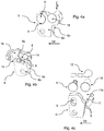
Figs. 4a and 4b show perspective front and rear views of a section of the actuator shown inFigs. 3a to 3c ; -
Fig. 4c shows an exploded front view of the actuator section shown inFigs. 4a and 4b ; -
Fig. 5a shows a sectional perspective view of the suspension arm and the actuator shown inFig. 2 ; -
Fig. 5b shows a partially exploded view of the suspension arm and the actuator shown inFig. 5a ; -
Fig. 6a shows a perspective front view of the suspension arm and the actuator shown inFigs. 5a and 5b ; -
Fig. 6b shows a perspective rear view of the suspension arm and the actuator shown inFig. 6a . -
Figs. 1a and 1b show a roof window comprising asash 1 and aframe 2 adapted for receiving thesash 1, thesash 1 being configured to pivot around a pivot axis A so as to open the sash towards an outer side of the window, i.e. towards the exterior of a building. Thesash 1 comprises twosash side members top sash member 1c and abottom sash member 1d. Thesash 1 may be suspended directly from theframe 2 or, optionally, suspended from theframe 2 by means ofsuspension arms 3. Eachoptional suspension arm 3 extends at least partially between asash side member frame side member - At least one
actuator 4 is provided to pivot thesash 1 between a closed position and several open positions, open positions being shown inFigs. 1a and 1b . Theactuator 4 is furthermore adapted for securing thesash 1 in the closed position. - As shown in more detail in
Figs. 2 and4a , theactuator 4 comprises a push-pull chain 5 and abracket 6, thebracket 6 being rigidly connected to afirst end 5a of the push-pull chain. Asecond end 5b of the push-pull chain is received in anactuator housing 7 connected to theframe 2, as shown schematically inFig. 1a . As thesash 1 is closed, the push-pull chain 5 is withdrawn, completely or almost completely, into theactuator housing 7 by an electrical motor (not shown). The push-pull chain 5 is maintained in the withdrawn position by means of the motor or any other suitable locking means, such that thesash 1 is maintained in the closed position until theactuator 4 is activated in order to move thesash 1 to an open position. - The push-
pull chain 5 comprises a plurality of coupledlinks 13, as shown inFig. 2 . In one embodiment, thelast link 13a at thefirst end 5a of the push-pull chain forms thebracket 6. In a further embodiment, thebracket 6 is a separate component connected to thelast link 13a of the push-pull chain 5. - The
bracket 6 comprises afirst opening 9 adapted for receiving areleasable connection pin 8, thereleasable connection pin 8 having afirst pin end 8a and asecond pin end 8b as shown inFigs. 3a to 3c . - The
releasable connection pin 8 connects thebracket 6 releasably to at least oneside sash member suspension arm 3, as shown inFigs. 5a and 5b as well as 6a and 6b. Thereleasable connection pin 8 extends in a direction substantially parallel with the pivot axis A, through thefirst opening 9 in the bracket and through at least one of asecond opening 10 in thesash side member third opening 11 in thesuspension arm 3. As thereleasable connection pin 8 connects thebracket 6 to theside sash member suspension arm 3, thefirst pin end 8a is arranged closer to the center C of the sash than thesecond pin end 8b. - Locking means 12, shown in
Figs. 4b and 4c , engage thefirst pin end 8a such that thereleasable connection pin 8 is prevented from being removed from thesecond opening 10 and/or thethird opening 11, as well as from thefirst opening 9. The locking means 12 comprises at least one of a threaded nut, a spring, a clip, a slider, and a pin. - The
first pin end 8a is configured for engaging the locking means 12 by means of a section having a reduced diameter arranged at thefirst pin end 8a, as shown inFig. 3c , or, as in a further embodiment, by means of a throughgoing channel 14 which extends perpendicular to the center axis CA of thereleasable connection pin 8, and which receives a part of the locking means 12 such as, e.g., one leg of a spring as shown inFig. 4b . - In one embodiment, the
releasable connection pin 8 extends through thesecond opening 10 of thesash side member first pin end 8a and the locking means 12 are arranged in a recess within thesash side member sash 1, in a direction towards the closestframe side member second pin end 8b is arranged between theframe side member sash side member releasable connection pin 8 extends, in other words, through thefirst opening 9 and thesecond opening 10. - If the window also comprises
suspension arms 3, thesecond pin end 8b may be arranged either between theframe side member suspension arm 3, or between thesuspension arm 3 and thesash side member second pin end 8b is arranged between theframe side member suspension arm 3, thereleasable connection pin 8 also extends through thethird opening 11 of thesuspension arm 3, i.e. thereleasable connection pin 8 extends through thefirst opening 9, thethird opening 11, and thesecond opening 10. - In one embodiment, the
releasable connection pin 8 extends through thethird opening 11 of thesuspension arm 3, and thefirst pin end 8a and the locking means 12 are arranged between thesuspension arm 3 and thesash side member second pin end 8b is arranged between theframe side member suspension arm 3. Thereleasable connection pin 8 extends, in other words, through thefirst opening 9 and thethird opening 11. - As shown in
Figs. 3a to 3c ,5a to 5b , and6a to 6b , thesuspension arm 3 may comprise aledge 3a extending parallel with the center axis of thethird opening 11, such that theledge 3a at least partially covers any existing gap between thesuspension arm 3 and thesash side member - The
second pin end 8b comprises an enlarged portion too large to pass through the first 9 and second 10 openings or the first 9 and third 11 openings, or even the first 9, second 10, and third 11 openings, such that thereleasable connection pin 8 can only be withdrawn from theopenings first pin end 8a to thesecond pin end 8b. Thefirst pin end 8a receives a part of the locking means 12, which prevents thereleasable connection pin 8 from being withdrawn from theopenings first pin end 8a to thesecond pin end 8b. The locking means 12 has to be released from thefirst pin end 8a in order to be able to withdraw thereleasable connection pin 8 from theopenings - As shown in
Figs. 3b, 3c , and5b , theactuator 4 may comprise aprotective casing 15 adapted for enclosing the locking means 12 and thefirst pin end 8a. Thecasing 15 comprises two casing halves interlocking with each other such that a void is formed between the casing halves, the void accommodating the locking means 12 and preferably thefirst pin end 8a. One casing half comprises anaccess opening 15a which allows access to the locking means 12, from the interior of the building, such that the locking means 12 can be released from thereleasable connection pin 8. Correspondingly, the other casing half comprises an opening allowing thereleasable connection pin 8 to pass through and enter the void formed by the two casing halves. In one embodiment, shown inFigs. 3a to 3c , eachsuspension arm 3 has an upside-down U-shaped cross-section enclosing the locking means 12 and thecasing 15. The two parallel legs of the U-shape are of different heights, the shorter leg extending the open end of the U-shape. The open end of the U-shape is at least partially directed towards the closestframe side member frame side member suspension arm 3 when the window is in the closed position. The locking means 12, arranged such that it is enclosed by theU-shaped suspension arm 3, is accessible through awall opening 16 in awall 3b of the U-shaped cross-section. Thewall 3b extends adjacent thesash side member ledge 3a. Thewall 3b corresponds to the longer of the two parallel legs of the U-shape. - In one embodiment, the
actuator 4 is adapted for pivoting thesash 1 in relation to theframe 2 against a load L of thesash 1, the load L mainly being caused by the weight of thesash 1 but possibly also by external conditions such as snow resting on the sash or wind. The push-pull chain 5 bends freely in a first direction D1, at least partially towards the pivot axis A, past a configuration in which the push-pull chain forms astraight line 5c, shown inFig. 2 , such that at least the main part of the push-pull chain 6 can be collapsed and wound together. The push-pull chain 5 can bend only to a limited extent past thestraight line 5c configuration in a second opposite direction D2, allowing the push-pull chain 5 to form an arc. Thebracket 6 provides at least one support point S for supporting the load L of thesash 1, as shown inFigs. 4a to 4c . The support point S is laterally offset from the longitudinal extent of the push-pull chain 5 so that the load L of thesash 1 urges the push-pull chain 5 to bend in the second opposite direction D2. - The
first opening 9 is preferably oblong and the longitudinal extent of thefirst opening 9 aligned with the longitudinal extent of the push-pull chain 5. Thereleasable connection pin 8 is allowed to move in thefirst opening 9 in the direction of the longitudinal extent of thefirst opening 9. - The
bracket 6 may comprise afourth opening 17 adapted for receiving apre-loading pin 18. Thefourth opening 17 is essentially a U-shaped recess having anopen end 17a, facing away from the push-pull chain 5, allowing thepre-loading pin 18 to exit thefourth opening 17 in one direction. Thepre-loading pin 18 extends through thefourth opening 17 and connects thebracket 6 rigidly to thesash 1. The load L of thesash 1 urges the push-pull chain 5 to bend in the second opposite direction D2 by thepre-loading pin 18 applying the load L of thesash 1 onto thebracket 6. - The center axis CA of the
connection pin 8 and the center axis CA2 of thepre-loading pin 18 extend parallel with each other and substantially parallel with the pivot axis A. - The
open end 17a of thefourth opening 17 allows thepre-loading pin 18 to at least partially exit thefourth opening 17, in a direction parallel with the longitudinal extent of the oblongfirst opening 9, if the load L applied by thesash 1 is reduced or reversed. - In one embodiment, the roof window further comprises a connecting
plate 19 connected to at least one of thesash 1 and thesuspension arm 3. The connectingplate 19 comprisesconnection openings 20 aligned with the oblongfirst opening 9 and thefourth opening 17, such that theconnection pin 8 and thepre-loading pin 18 may extend through theconnection openings 20. - The
bracket 6 may comprise first and secondparallel bracket plates first opening 9 in thefirst bracket plate 6a is aligned with the oblongfirst opening 9 in thesecond bracket plate 6b, and thefourth opening 17 in thefirst bracket plate 6a is aligned with thefourth opening 17 in thesecond bracket plate 6b, Thebracket 6 encloses the connectingplate 19 at least partially such that the first andsecond bracket plates plate 19. - In one embodiment, the
actuator 4 further comprises chain support means 21, connected to at least one of thesash 1 and theframe 2. The chain support means 21 provide a stabilizing force F onto the push-pull chain 5 perpendicularly to the longitudinal extension of the push-pull chain 5, such that the stabilizing force F urges the push-pull chain to bend in the second opposite direction D2, as shown inFig. 2 . - In one embodiment, the roof window is a top-hung roof window comprising one
actuator 4, theactuator 4 being arranged adjacent a frame bottom member 2d. - In a further embodiment, the roof window is a center-pivoted roof window or a top-hung roof window comprising two
actuators 4, eachactuator 4 being arranged adjacent oneframe side member - The present roof window has several benefits. For example, it enables large opening angles. Another benefit is having a large load capacity which remains stable with changing roof angles and during high load conditions (any push-pull situations which occur). A further benefit is that the push-pull chains can be placed substantially out of sight at the sides of the window, allowing the window to have a slenderer appearance and providing a better view. Additionally, the need for window load balancing by springs is reduced, such that the springs do not need adjustment or may be entirely omitted. Another benefit is that the push-pull chain actuator may keep the window closed without additional need for a window lock. Furthermore, the window installation process and the process of connecting the push-pull chain(s) is enhanced. Finally, the push-pull chain is burglar protected while still enabling service of the window.
- The various aspects and implementations have been described in conjunction with various embodiments herein. However, other variations to the disclosed embodiments can be understood and effected by those skilled in the art in practicing the claimed subject-matter, from a study of the drawings, the disclosure, and the appended claims. In the claims, the word "comprising" does not exclude other elements or steps, and the indefinite article "a" or "an" does not exclude a plurality. The mere fact that certain measures are recited in mutually different dependent claims does not indicate that a combination of these measured cannot be used to advantage.
- The reference signs used in the claims shall not be construed as limiting the scope.
Claims (15)
- A roof window comprising a sash (1) and a frame (2) adapted for receiving said sash (1), said sash (1) comprising two sash side members (1a, 1b) connected to a top sash member (1c) and a bottom sash member (1d), said sash (1) optionally being suspended from said frame by means of suspension arms (3), said sash (1) being configured to pivot around a pivot axis (A) so as to open said sash towards an outer side of said window, each optional suspension arm (3) extending at least partially between a sash side member (1a, 1b) and a frame side member (2a, 2b),
said roof window further comprising:at least one actuator (4) adapted for pivoting said sash (1) between a closed position and open positions, said actuator (4) being adapted for securing said sash (1) in said closed position,said actuator (4) comprising a push-pull chain (5) and a bracket (6), said bracket (6) being rigidly connected to a first end (5a) of said push-pull chain, a second end (5b) of said push-pull chain being received in an actuator housing (7) connected to said frame (2),a releasable connection pin (8) with a first pin end (8a) and a second pin end (8b),said bracket (6) comprising a first opening (9) adapted for receiving said releasable connection pin (8),said releasable connection pin (8) releasably connecting said bracket (6) to at least one of said side sash member (1a, 1b) and said suspension arm (3) by said releasable connection pin (8) extending in a direction substantially parallel with said pivot axis (A) through said first opening (9) and through at least one of a second opening (10) in said sash side member (1a, 1b) and a third opening (11) in said suspension arm (3), and with said first pin end (8a) being arranged closer to a center (C) of said sash than said second pin end (8b),locking means (12) engaging said first pin end (8a), said locking means (12) being configured for preventing said releasable connection pin (8) from being removed from at least one of said second opening (10) and said third opening (11) . - The roof window according to claim 1, wherein said first pin end (8a) is configured for engaging said locking means (12) .
- The roof window according to claim 1 or 2, wherein said push-pull chain (5) comprises a plurality of coupled links (13), wherein a last link (13a) at said first end (5a) of said push-pull chain forms said bracket (6).
- The roof window according to any one of the previous claims, wherein said releasable connection pin (8) extends through said second opening (10) of said sash side member (1a, 1b), said first pin end (8a) and said locking means (12) being arranged in a recess within said sash side member (1a, 1b), said second pin end (8b) being arranged between said frame side member (2a, 2b) and said sash side member (1a, 1b).
- The roof window according to claim 4, wherein said releasable connection pin (8) furthermore extends through said third opening (11) of said suspension arm (3), said second pin end (8b) being arranged between said frame side member (2a, 2b) and said suspension arm (3).
- The roof window according to any one of claims 1 to 3, wherein said releasable connection pin (8) extends through said third opening (11) of said suspension arm (3), said first pin end (8a) and said locking means (12) being arranged between said suspension arm (3) and said sash side member (1a, 1b), said second pin end (8b) being arranged between said frame side member (2a, 2b) and said suspension arm (3).
- The roof window according to any one of the previous claims, wherein said suspension arm (3) comprises a ledge (3a) extending parallel with said third opening (11), said ledge (3a) at least partially covering a gap between said suspension arm (3) and said sash side member (1a, 1b).
- The roof window according to any one of the previous claims, wherein said locking means (12) comprises at least one of a threaded nut, a spring, a clip, a slider, and a pin.
- The roof window according to any one of the previous claims, wherein said second pin end (8b) comprises an enlarged portion too large to pass through at least one of said first opening (9), said second opening (10), and said third opening (11), and wherein said first pin end (8a) comprises a throughgoing channel (14), extending perpendicular to a center axis (CA) of said releasable connection pin (8), for receiving a part of said locking means (12).
- The roof window according to any one of the previous claims, wherein said actuator (4) further comprises a protective casing (15) adapted for enclosing said locking means (12) and said first pin end (8a).
- The roof window according to claim 10, wherein said casing (15) comprises two casing halves, one casing half comprising an access opening (15a) allowing access to said locking means (12) such that said locking means (12) can be released from said releasable connection pin (8).
- The roof window according to claim 10 or 11, wherein each suspension arm (3) has an upside-down U-shaped cross-section enclosing said locking means (12) and said casing (15), an open end of said U-shape being at least partially directed towards an adjacent frame side member (2a, 2b).
- The roof window according to claim 12, wherein said locking means (12) is accessible through a wall opening (16) in a wall (3b) of said U-shaped cross-section, said wall (3b) extending adjacent said sash side member (1a, 1b).
- The roof window according to any one of the previous claims, wherein said actuator (4) is adapted for pivoting said sash (1) in relation to said frame (2) against a load (L) of said sash (1), said load (L) mainly being caused by the weight of said sash (1),
said push-pull chain (5) being adapted for bending freely in a first direction (D1), past a configuration in which said push-pull chain forms a straight line (5c), and only to a limited extent past said straight line (5c) configuration in a second opposite direction (D2),
said bracket (6) providing a support point (S) for supporting the load (L) of said sash (1), said support point (S) being laterally offset from the longitudinal extent of said push-pull chain (5) so that the load (L) of said sash (1) urges said push-pull chain (5) to bend in said second opposite direction (D2),
said first opening (9) being oblong and the longitudinal extent of said first opening (9) being aligned with the longitudinal extent of said push-pull chain (5),
said releasable connection pin (8) being allowed to move in said first opening (9) in the direction of the longitudinal extent of said first opening (9), the longitudinal extent of said first opening (9) being aligned with the longitudinal extent of said push-pull chain (5). - The roof window according to claim 14, wherein said bracket (6) comprises a fourth opening (17) adapted for receiving a pre-loading pin (18), said pre-loading pin (18) extending through said fourth opening (17) and connecting said bracket (6) to said sash (1),
the load (L) of said sash (1) urging said push-pull chain (5) to bend in said second opposite direction (D2) by said pre-loading pin (18) applying the load (L) of said sash (1) onto said bracket (6).
Applications Claiming Priority (1)
| Application Number | Priority Date | Filing Date | Title |
|---|---|---|---|
| DKPA201870724 | 2018-11-02 |
Publications (2)
| Publication Number | Publication Date |
|---|---|
| EP3647520A1 true EP3647520A1 (en) | 2020-05-06 |
| EP3647520B1 EP3647520B1 (en) | 2024-03-27 |
Family
ID=68281154
Family Applications (1)
| Application Number | Title | Priority Date | Filing Date |
|---|---|---|---|
| EP19203528.5A Active EP3647520B1 (en) | 2018-11-02 | 2019-10-16 | Intrusion-safe roof window |
Country Status (1)
| Country | Link |
|---|---|
| EP (1) | EP3647520B1 (en) |
Citations (5)
| Publication number | Priority date | Publication date | Assignee | Title |
|---|---|---|---|---|
| WO2002031304A1 (en) | 2000-10-10 | 2002-04-18 | Vkr Holding A/S | Rain sensor arrangement |
| DE20204224U1 (en) * | 2002-03-16 | 2002-05-23 | Aug. Winkhaus GmbH & Co. KG, 48291 Telgte | Device for issuing and locking a wing pivotally arranged on a frame |
| DE202010000269U1 (en) * | 2010-02-26 | 2011-08-23 | Stg-Beikirch Industrieelektronik + Sicherheitstechnik Gmbh & Co. Kg | Bearing block and Ausstellinrichtung |
| US20110302843A1 (en) * | 2010-06-11 | 2011-12-15 | Dallmann Brian D | Window drive with back-curving chain |
| DE102016203452A1 (en) * | 2016-03-02 | 2017-09-07 | Geze Gmbh | drive |
-
2019
- 2019-10-16 EP EP19203528.5A patent/EP3647520B1/en active Active
Patent Citations (5)
| Publication number | Priority date | Publication date | Assignee | Title |
|---|---|---|---|---|
| WO2002031304A1 (en) | 2000-10-10 | 2002-04-18 | Vkr Holding A/S | Rain sensor arrangement |
| DE20204224U1 (en) * | 2002-03-16 | 2002-05-23 | Aug. Winkhaus GmbH & Co. KG, 48291 Telgte | Device for issuing and locking a wing pivotally arranged on a frame |
| DE202010000269U1 (en) * | 2010-02-26 | 2011-08-23 | Stg-Beikirch Industrieelektronik + Sicherheitstechnik Gmbh & Co. Kg | Bearing block and Ausstellinrichtung |
| US20110302843A1 (en) * | 2010-06-11 | 2011-12-15 | Dallmann Brian D | Window drive with back-curving chain |
| DE102016203452A1 (en) * | 2016-03-02 | 2017-09-07 | Geze Gmbh | drive |
Also Published As
| Publication number | Publication date |
|---|---|
| EP3647520B1 (en) | 2024-03-27 |
Similar Documents
| Publication | Publication Date | Title |
|---|---|---|
| EP3647521B1 (en) | Roof window comprising a pre-stressed chain actuator | |
| EP3936693B1 (en) | Roof window with a primary frame and at least one secondary frame, method for installing such a roof window and method for dismantling a secondary frame of the roof window | |
| US4476652A (en) | Device for suspending a slidable sealed door | |
| EP2060713B1 (en) | Anti-effraction safety system for door and window frames | |
| US7793463B1 (en) | Plantation style security shutters | |
| US6588482B2 (en) | Cable attachment bracket for articulating garage door panels | |
| EP3647520B1 (en) | Intrusion-safe roof window | |
| JP2009280995A (en) | Door lock structure of switch gear | |
| JP7053254B2 (en) | Door asset | |
| KR101733551B1 (en) | Security windoow be able to opening and closing in the room | |
| EP4296463A1 (en) | Integrating communication lines into profiles | |
| JP6393108B2 (en) | Hinge device and joinery | |
| JP6335593B2 (en) | Sliding door device with emergency release type stopper | |
| KR101591733B1 (en) | Sag adjustment system for emergency opening door for sliding automatic door | |
| JP2017133263A (en) | Fitting | |
| JP2019206799A (en) | Shutter apparatus | |
| KR102107513B1 (en) | Window structure of building for apartment house | |
| EP3290614B1 (en) | A roof window with improved insulation properties and including a set of hinges | |
| KR102595301B1 (en) | Interior stop device for window frame of apartment house | |
| EP3241975B1 (en) | Motorized roller shutter | |
| EP0589822B1 (en) | Device for opening a window or a door, especially of the sliding type | |
| EP4424964A1 (en) | Arm actuator for pivoting a building element | |
| JP6401636B2 (en) | Architectural shutter device | |
| JP7610271B2 (en) | Shutter reinforcement device | |
| KR100567213B1 (en) | Fire shutter |
Legal Events
| Date | Code | Title | Description |
|---|---|---|---|
| PUAI | Public reference made under article 153(3) epc to a published international application that has entered the european phase |
Free format text: ORIGINAL CODE: 0009012 |
|
| STAA | Information on the status of an ep patent application or granted ep patent |
Free format text: STATUS: THE APPLICATION HAS BEEN PUBLISHED |
|
| STAA | Information on the status of an ep patent application or granted ep patent |
Free format text: STATUS: REQUEST FOR EXAMINATION WAS MADE |
|
| AK | Designated contracting states |
Kind code of ref document: A1 Designated state(s): AL AT BE BG CH CY CZ DE DK EE ES FI FR GB GR HR HU IE IS IT LI LT LU LV MC MK MT NL NO PL PT RO RS SE SI SK SM TR |
|
| AX | Request for extension of the european patent |
Extension state: BA ME |
|
| 17P | Request for examination filed |
Effective date: 20200421 |
|
| RBV | Designated contracting states (corrected) |
Designated state(s): AL AT BE BG CH CY CZ DE DK EE ES FI FR GB GR HR HU IE IS IT LI LT LU LV MC MK MT NL NO PL PT RO RS SE SI SK SM TR |
|
| GRAP | Despatch of communication of intention to grant a patent |
Free format text: ORIGINAL CODE: EPIDOSNIGR1 |
|
| STAA | Information on the status of an ep patent application or granted ep patent |
Free format text: STATUS: GRANT OF PATENT IS INTENDED |
|
| INTG | Intention to grant announced |
Effective date: 20231023 |
|
| GRAS | Grant fee paid |
Free format text: ORIGINAL CODE: EPIDOSNIGR3 |
|
| GRAA | (expected) grant |
Free format text: ORIGINAL CODE: 0009210 |
|
| STAA | Information on the status of an ep patent application or granted ep patent |
Free format text: STATUS: THE PATENT HAS BEEN GRANTED |
|
| AK | Designated contracting states |
Kind code of ref document: B1 Designated state(s): AL AT BE BG CH CY CZ DE DK EE ES FI FR GB GR HR HU IE IS IT LI LT LU LV MC MK MT NL NO PL PT RO RS SE SI SK SM TR |
|
| REG | Reference to a national code |
Ref country code: GB Ref legal event code: FG4D |
|
| REG | Reference to a national code |
Ref country code: CH Ref legal event code: EP |
|
| REG | Reference to a national code |
Ref country code: DE Ref legal event code: R096 Ref document number: 602019048925 Country of ref document: DE |
|
| REG | Reference to a national code |
Ref country code: IE Ref legal event code: FG4D |
|
| PG25 | Lapsed in a contracting state [announced via postgrant information from national office to epo] |
Ref country code: LT Free format text: LAPSE BECAUSE OF FAILURE TO SUBMIT A TRANSLATION OF THE DESCRIPTION OR TO PAY THE FEE WITHIN THE PRESCRIBED TIME-LIMIT Effective date: 20240327 |
|
| REG | Reference to a national code |
Ref country code: LT Ref legal event code: MG9D |
|
| PG25 | Lapsed in a contracting state [announced via postgrant information from national office to epo] |
Ref country code: GR Free format text: LAPSE BECAUSE OF FAILURE TO SUBMIT A TRANSLATION OF THE DESCRIPTION OR TO PAY THE FEE WITHIN THE PRESCRIBED TIME-LIMIT Effective date: 20240628 |
|
| PG25 | Lapsed in a contracting state [announced via postgrant information from national office to epo] |
Ref country code: HR Free format text: LAPSE BECAUSE OF FAILURE TO SUBMIT A TRANSLATION OF THE DESCRIPTION OR TO PAY THE FEE WITHIN THE PRESCRIBED TIME-LIMIT Effective date: 20240327 Ref country code: RS Free format text: LAPSE BECAUSE OF FAILURE TO SUBMIT A TRANSLATION OF THE DESCRIPTION OR TO PAY THE FEE WITHIN THE PRESCRIBED TIME-LIMIT Effective date: 20240627 |
|
| PG25 | Lapsed in a contracting state [announced via postgrant information from national office to epo] |
Ref country code: RS Free format text: LAPSE BECAUSE OF FAILURE TO SUBMIT A TRANSLATION OF THE DESCRIPTION OR TO PAY THE FEE WITHIN THE PRESCRIBED TIME-LIMIT Effective date: 20240627 Ref country code: NO Free format text: LAPSE BECAUSE OF FAILURE TO SUBMIT A TRANSLATION OF THE DESCRIPTION OR TO PAY THE FEE WITHIN THE PRESCRIBED TIME-LIMIT Effective date: 20240627 Ref country code: LT Free format text: LAPSE BECAUSE OF FAILURE TO SUBMIT A TRANSLATION OF THE DESCRIPTION OR TO PAY THE FEE WITHIN THE PRESCRIBED TIME-LIMIT Effective date: 20240327 Ref country code: HR Free format text: LAPSE BECAUSE OF FAILURE TO SUBMIT A TRANSLATION OF THE DESCRIPTION OR TO PAY THE FEE WITHIN THE PRESCRIBED TIME-LIMIT Effective date: 20240327 Ref country code: GR Free format text: LAPSE BECAUSE OF FAILURE TO SUBMIT A TRANSLATION OF THE DESCRIPTION OR TO PAY THE FEE WITHIN THE PRESCRIBED TIME-LIMIT Effective date: 20240628 Ref country code: FI Free format text: LAPSE BECAUSE OF FAILURE TO SUBMIT A TRANSLATION OF THE DESCRIPTION OR TO PAY THE FEE WITHIN THE PRESCRIBED TIME-LIMIT Effective date: 20240327 Ref country code: BG Free format text: LAPSE BECAUSE OF FAILURE TO SUBMIT A TRANSLATION OF THE DESCRIPTION OR TO PAY THE FEE WITHIN THE PRESCRIBED TIME-LIMIT Effective date: 20240327 |
|
| REG | Reference to a national code |
Ref country code: NL Ref legal event code: MP Effective date: 20240327 |
|
| PG25 | Lapsed in a contracting state [announced via postgrant information from national office to epo] |
Ref country code: SE Free format text: LAPSE BECAUSE OF FAILURE TO SUBMIT A TRANSLATION OF THE DESCRIPTION OR TO PAY THE FEE WITHIN THE PRESCRIBED TIME-LIMIT Effective date: 20240327 Ref country code: LV Free format text: LAPSE BECAUSE OF FAILURE TO SUBMIT A TRANSLATION OF THE DESCRIPTION OR TO PAY THE FEE WITHIN THE PRESCRIBED TIME-LIMIT Effective date: 20240327 |
|
| PG25 | Lapsed in a contracting state [announced via postgrant information from national office to epo] |
Ref country code: NL Free format text: LAPSE BECAUSE OF FAILURE TO SUBMIT A TRANSLATION OF THE DESCRIPTION OR TO PAY THE FEE WITHIN THE PRESCRIBED TIME-LIMIT Effective date: 20240327 |
|
| REG | Reference to a national code |
Ref country code: AT Ref legal event code: MK05 Ref document number: 1670065 Country of ref document: AT Kind code of ref document: T Effective date: 20240327 |
|
| PG25 | Lapsed in a contracting state [announced via postgrant information from national office to epo] |
Ref country code: NL Free format text: LAPSE BECAUSE OF FAILURE TO SUBMIT A TRANSLATION OF THE DESCRIPTION OR TO PAY THE FEE WITHIN THE PRESCRIBED TIME-LIMIT Effective date: 20240327 |
|
| PG25 | Lapsed in a contracting state [announced via postgrant information from national office to epo] |
Ref country code: IS Free format text: LAPSE BECAUSE OF FAILURE TO SUBMIT A TRANSLATION OF THE DESCRIPTION OR TO PAY THE FEE WITHIN THE PRESCRIBED TIME-LIMIT Effective date: 20240727 |
|
| PG25 | Lapsed in a contracting state [announced via postgrant information from national office to epo] |
Ref country code: PT Free format text: LAPSE BECAUSE OF FAILURE TO SUBMIT A TRANSLATION OF THE DESCRIPTION OR TO PAY THE FEE WITHIN THE PRESCRIBED TIME-LIMIT Effective date: 20240729 Ref country code: SM Free format text: LAPSE BECAUSE OF FAILURE TO SUBMIT A TRANSLATION OF THE DESCRIPTION OR TO PAY THE FEE WITHIN THE PRESCRIBED TIME-LIMIT Effective date: 20240327 |
|
| PG25 | Lapsed in a contracting state [announced via postgrant information from national office to epo] |
Ref country code: ES Free format text: LAPSE BECAUSE OF FAILURE TO SUBMIT A TRANSLATION OF THE DESCRIPTION OR TO PAY THE FEE WITHIN THE PRESCRIBED TIME-LIMIT Effective date: 20240327 |
|
| PG25 | Lapsed in a contracting state [announced via postgrant information from national office to epo] |
Ref country code: CZ Free format text: LAPSE BECAUSE OF FAILURE TO SUBMIT A TRANSLATION OF THE DESCRIPTION OR TO PAY THE FEE WITHIN THE PRESCRIBED TIME-LIMIT Effective date: 20240327 Ref country code: EE Free format text: LAPSE BECAUSE OF FAILURE TO SUBMIT A TRANSLATION OF THE DESCRIPTION OR TO PAY THE FEE WITHIN THE PRESCRIBED TIME-LIMIT Effective date: 20240327 |
|
| PG25 | Lapsed in a contracting state [announced via postgrant information from national office to epo] |
Ref country code: AT Free format text: LAPSE BECAUSE OF FAILURE TO SUBMIT A TRANSLATION OF THE DESCRIPTION OR TO PAY THE FEE WITHIN THE PRESCRIBED TIME-LIMIT Effective date: 20240327 |
|
| PG25 | Lapsed in a contracting state [announced via postgrant information from national office to epo] |
Ref country code: PL Free format text: LAPSE BECAUSE OF FAILURE TO SUBMIT A TRANSLATION OF THE DESCRIPTION OR TO PAY THE FEE WITHIN THE PRESCRIBED TIME-LIMIT Effective date: 20240327 |
|
| PG25 | Lapsed in a contracting state [announced via postgrant information from national office to epo] |
Ref country code: SK Free format text: LAPSE BECAUSE OF FAILURE TO SUBMIT A TRANSLATION OF THE DESCRIPTION OR TO PAY THE FEE WITHIN THE PRESCRIBED TIME-LIMIT Effective date: 20240327 |
|
| PG25 | Lapsed in a contracting state [announced via postgrant information from national office to epo] |
Ref country code: SM Free format text: LAPSE BECAUSE OF FAILURE TO SUBMIT A TRANSLATION OF THE DESCRIPTION OR TO PAY THE FEE WITHIN THE PRESCRIBED TIME-LIMIT Effective date: 20240327 Ref country code: SK Free format text: LAPSE BECAUSE OF FAILURE TO SUBMIT A TRANSLATION OF THE DESCRIPTION OR TO PAY THE FEE WITHIN THE PRESCRIBED TIME-LIMIT Effective date: 20240327 Ref country code: RO Free format text: LAPSE BECAUSE OF FAILURE TO SUBMIT A TRANSLATION OF THE DESCRIPTION OR TO PAY THE FEE WITHIN THE PRESCRIBED TIME-LIMIT Effective date: 20240327 Ref country code: PT Free format text: LAPSE BECAUSE OF FAILURE TO SUBMIT A TRANSLATION OF THE DESCRIPTION OR TO PAY THE FEE WITHIN THE PRESCRIBED TIME-LIMIT Effective date: 20240729 Ref country code: PL Free format text: LAPSE BECAUSE OF FAILURE TO SUBMIT A TRANSLATION OF THE DESCRIPTION OR TO PAY THE FEE WITHIN THE PRESCRIBED TIME-LIMIT Effective date: 20240327 Ref country code: IS Free format text: LAPSE BECAUSE OF FAILURE TO SUBMIT A TRANSLATION OF THE DESCRIPTION OR TO PAY THE FEE WITHIN THE PRESCRIBED TIME-LIMIT Effective date: 20240727 Ref country code: ES Free format text: LAPSE BECAUSE OF FAILURE TO SUBMIT A TRANSLATION OF THE DESCRIPTION OR TO PAY THE FEE WITHIN THE PRESCRIBED TIME-LIMIT Effective date: 20240327 Ref country code: EE Free format text: LAPSE BECAUSE OF FAILURE TO SUBMIT A TRANSLATION OF THE DESCRIPTION OR TO PAY THE FEE WITHIN THE PRESCRIBED TIME-LIMIT Effective date: 20240327 Ref country code: CZ Free format text: LAPSE BECAUSE OF FAILURE TO SUBMIT A TRANSLATION OF THE DESCRIPTION OR TO PAY THE FEE WITHIN THE PRESCRIBED TIME-LIMIT Effective date: 20240327 Ref country code: AT Free format text: LAPSE BECAUSE OF FAILURE TO SUBMIT A TRANSLATION OF THE DESCRIPTION OR TO PAY THE FEE WITHIN THE PRESCRIBED TIME-LIMIT Effective date: 20240327 |
|
| PG25 | Lapsed in a contracting state [announced via postgrant information from national office to epo] |
Ref country code: IT Free format text: LAPSE BECAUSE OF FAILURE TO SUBMIT A TRANSLATION OF THE DESCRIPTION OR TO PAY THE FEE WITHIN THE PRESCRIBED TIME-LIMIT Effective date: 20240327 |
|
| PG25 | Lapsed in a contracting state [announced via postgrant information from national office to epo] |
Ref country code: IT Free format text: LAPSE BECAUSE OF FAILURE TO SUBMIT A TRANSLATION OF THE DESCRIPTION OR TO PAY THE FEE WITHIN THE PRESCRIBED TIME-LIMIT Effective date: 20240327 |
|
| REG | Reference to a national code |
Ref country code: DE Ref legal event code: R097 Ref document number: 602019048925 Country of ref document: DE |
|
| PG25 | Lapsed in a contracting state [announced via postgrant information from national office to epo] |
Ref country code: DK Free format text: LAPSE BECAUSE OF FAILURE TO SUBMIT A TRANSLATION OF THE DESCRIPTION OR TO PAY THE FEE WITHIN THE PRESCRIBED TIME-LIMIT Effective date: 20240327 |
|
| PG25 | Lapsed in a contracting state [announced via postgrant information from national office to epo] |
Ref country code: DK Free format text: LAPSE BECAUSE OF FAILURE TO SUBMIT A TRANSLATION OF THE DESCRIPTION OR TO PAY THE FEE WITHIN THE PRESCRIBED TIME-LIMIT Effective date: 20240327 |
|
| PLBE | No opposition filed within time limit |
Free format text: ORIGINAL CODE: 0009261 |
|
| STAA | Information on the status of an ep patent application or granted ep patent |
Free format text: STATUS: NO OPPOSITION FILED WITHIN TIME LIMIT |
|
| 26N | No opposition filed |
Effective date: 20250103 |
|
| PG25 | Lapsed in a contracting state [announced via postgrant information from national office to epo] |
Ref country code: SI Free format text: LAPSE BECAUSE OF FAILURE TO SUBMIT A TRANSLATION OF THE DESCRIPTION OR TO PAY THE FEE WITHIN THE PRESCRIBED TIME-LIMIT Effective date: 20240327 |
|
| REG | Reference to a national code |
Ref country code: CH Ref legal event code: PL |
|
| GBPC | Gb: european patent ceased through non-payment of renewal fee |
Effective date: 20241016 |
|
| PG25 | Lapsed in a contracting state [announced via postgrant information from national office to epo] |
Ref country code: MC Free format text: LAPSE BECAUSE OF FAILURE TO SUBMIT A TRANSLATION OF THE DESCRIPTION OR TO PAY THE FEE WITHIN THE PRESCRIBED TIME-LIMIT Effective date: 20240327 |
|
| PG25 | Lapsed in a contracting state [announced via postgrant information from national office to epo] |
Ref country code: GB Free format text: LAPSE BECAUSE OF NON-PAYMENT OF DUE FEES Effective date: 20241016 |
|
| PG25 | Lapsed in a contracting state [announced via postgrant information from national office to epo] |
Ref country code: BE Free format text: LAPSE BECAUSE OF NON-PAYMENT OF DUE FEES Effective date: 20241031 Ref country code: LU Free format text: LAPSE BECAUSE OF NON-PAYMENT OF DUE FEES Effective date: 20241016 |
|
| PG25 | Lapsed in a contracting state [announced via postgrant information from national office to epo] |
Ref country code: CH Free format text: LAPSE BECAUSE OF NON-PAYMENT OF DUE FEES Effective date: 20241031 |
|
| REG | Reference to a national code |
Ref country code: BE Ref legal event code: MM Effective date: 20241031 |
|
| PGFP | Annual fee paid to national office [announced via postgrant information from national office to epo] |
Ref country code: FR Payment date: 20250908 Year of fee payment: 7 |
|
| PG25 | Lapsed in a contracting state [announced via postgrant information from national office to epo] |
Ref country code: IE Free format text: LAPSE BECAUSE OF NON-PAYMENT OF DUE FEES Effective date: 20241016 |
|
| PGFP | Annual fee paid to national office [announced via postgrant information from national office to epo] |
Ref country code: DE Payment date: 20250902 Year of fee payment: 7 |
|
| PG25 | Lapsed in a contracting state [announced via postgrant information from national office to epo] |
Ref country code: CY Free format text: LAPSE BECAUSE OF FAILURE TO SUBMIT A TRANSLATION OF THE DESCRIPTION OR TO PAY THE FEE WITHIN THE PRESCRIBED TIME-LIMIT; INVALID AB INITIO Effective date: 20191016 |
|
| PG25 | Lapsed in a contracting state [announced via postgrant information from national office to epo] |
Ref country code: HU Free format text: LAPSE BECAUSE OF FAILURE TO SUBMIT A TRANSLATION OF THE DESCRIPTION OR TO PAY THE FEE WITHIN THE PRESCRIBED TIME-LIMIT; INVALID AB INITIO Effective date: 20191016 |