EP3647491A1 - Method, system, rotating machine element and computer program product for measuring the moisture of a fibre web in a tissue machine - Google Patents
Method, system, rotating machine element and computer program product for measuring the moisture of a fibre web in a tissue machine Download PDFInfo
- Publication number
- EP3647491A1 EP3647491A1 EP19205543.2A EP19205543A EP3647491A1 EP 3647491 A1 EP3647491 A1 EP 3647491A1 EP 19205543 A EP19205543 A EP 19205543A EP 3647491 A1 EP3647491 A1 EP 3647491A1
- Authority
- EP
- European Patent Office
- Prior art keywords
- fibre web
- machine
- temperature
- sensor assembly
- moisture
- Prior art date
- Legal status (The legal status is an assumption and is not a legal conclusion. Google has not performed a legal analysis and makes no representation as to the accuracy of the status listed.)
- Pending
Links
- 239000000835 fiber Substances 0.000 title claims abstract description 185
- 238000000034 method Methods 0.000 title claims abstract description 70
- 238000004590 computer program Methods 0.000 title claims abstract description 13
- 238000000576 coating method Methods 0.000 claims abstract description 40
- 239000011248 coating agent Substances 0.000 claims abstract description 38
- 238000005259 measurement Methods 0.000 claims description 84
- 239000004744 fabric Substances 0.000 claims description 64
- 238000001035 drying Methods 0.000 claims description 47
- 238000009529 body temperature measurement Methods 0.000 claims description 41
- 238000012546 transfer Methods 0.000 claims description 21
- 238000012545 processing Methods 0.000 claims description 7
- 238000000418 atomic force spectrum Methods 0.000 claims description 5
- 238000003860 storage Methods 0.000 claims description 3
- 239000000945 filler Substances 0.000 claims description 2
- 238000009434 installation Methods 0.000 description 14
- 239000010410 layer Substances 0.000 description 12
- 238000012544 monitoring process Methods 0.000 description 10
- 238000004519 manufacturing process Methods 0.000 description 8
- 230000003068 static effect Effects 0.000 description 8
- 238000004148 unit process Methods 0.000 description 7
- 238000004458 analytical method Methods 0.000 description 5
- 239000000463 material Substances 0.000 description 5
- 239000000047 product Substances 0.000 description 5
- 238000004513 sizing Methods 0.000 description 5
- 230000006870 function Effects 0.000 description 4
- 230000006698 induction Effects 0.000 description 4
- 230000006978 adaptation Effects 0.000 description 3
- 238000003490 calendering Methods 0.000 description 3
- 239000011247 coating layer Substances 0.000 description 3
- 230000005540 biological transmission Effects 0.000 description 2
- 239000007795 chemical reaction product Substances 0.000 description 2
- 239000004020 conductor Substances 0.000 description 2
- 238000001816 cooling Methods 0.000 description 2
- 230000000694 effects Effects 0.000 description 2
- 238000010438 heat treatment Methods 0.000 description 2
- 238000002847 impedance measurement Methods 0.000 description 2
- 239000004642 Polyimide Substances 0.000 description 1
- 239000004809 Teflon Substances 0.000 description 1
- 229920006362 Teflon® Polymers 0.000 description 1
- 238000004364 calculation method Methods 0.000 description 1
- 238000004891 communication Methods 0.000 description 1
- 239000002131 composite material Substances 0.000 description 1
- 230000001627 detrimental effect Effects 0.000 description 1
- 230000008030 elimination Effects 0.000 description 1
- 238000003379 elimination reaction Methods 0.000 description 1
- 238000004049 embossing Methods 0.000 description 1
- 238000005516 engineering process Methods 0.000 description 1
- 230000005284 excitation Effects 0.000 description 1
- 229920001721 polyimide Polymers 0.000 description 1
- 229920000642 polymer Polymers 0.000 description 1
- 238000003825 pressing Methods 0.000 description 1
- 230000002265 prevention Effects 0.000 description 1
- 238000007639 printing Methods 0.000 description 1
- 239000004065 semiconductor Substances 0.000 description 1
- 238000004381 surface treatment Methods 0.000 description 1
- XLYOFNOQVPJJNP-UHFFFAOYSA-N water Substances O XLYOFNOQVPJJNP-UHFFFAOYSA-N 0.000 description 1
- 238000004804 winding Methods 0.000 description 1
Images

Classifications
-
- D—TEXTILES; PAPER
- D21—PAPER-MAKING; PRODUCTION OF CELLULOSE
- D21F—PAPER-MAKING MACHINES; METHODS OF PRODUCING PAPER THEREON
- D21F7/00—Other details of machines for making continuous webs of paper
- D21F7/003—Indicating or regulating the moisture content of the layer
-
- D—TEXTILES; PAPER
- D21—PAPER-MAKING; PRODUCTION OF CELLULOSE
- D21F—PAPER-MAKING MACHINES; METHODS OF PRODUCING PAPER THEREON
- D21F1/00—Wet end of machines for making continuous webs of paper
- D21F1/36—Guiding mechanisms
- D21F1/40—Rolls
-
- D—TEXTILES; PAPER
- D21—PAPER-MAKING; PRODUCTION OF CELLULOSE
- D21F—PAPER-MAKING MACHINES; METHODS OF PRODUCING PAPER THEREON
- D21F11/00—Processes for making continuous lengths of paper, or of cardboard, or of wet web for fibre board production, on paper-making machines
- D21F11/14—Making cellulose wadding, filter or blotting paper
-
- D—TEXTILES; PAPER
- D21—PAPER-MAKING; PRODUCTION OF CELLULOSE
- D21F—PAPER-MAKING MACHINES; METHODS OF PRODUCING PAPER THEREON
- D21F3/00—Press section of machines for making continuous webs of paper
- D21F3/02—Wet presses
- D21F3/08—Pressure rolls
-
- D—TEXTILES; PAPER
- D21—PAPER-MAKING; PRODUCTION OF CELLULOSE
- D21F—PAPER-MAKING MACHINES; METHODS OF PRODUCING PAPER THEREON
- D21F9/00—Complete machines for making continuous webs of paper
-
- D—TEXTILES; PAPER
- D21—PAPER-MAKING; PRODUCTION OF CELLULOSE
- D21G—CALENDERS; ACCESSORIES FOR PAPER-MAKING MACHINES
- D21G9/00—Other accessories for paper-making machines
- D21G9/0009—Paper-making control systems
-
- D—TEXTILES; PAPER
- D21—PAPER-MAKING; PRODUCTION OF CELLULOSE
- D21G—CALENDERS; ACCESSORIES FOR PAPER-MAKING MACHINES
- D21G9/00—Other accessories for paper-making machines
- D21G9/0009—Paper-making control systems
- D21G9/0036—Paper-making control systems controlling the press or drying section
-
- G—PHYSICS
- G01—MEASURING; TESTING
- G01K—MEASURING TEMPERATURE; MEASURING QUANTITY OF HEAT; THERMALLY-SENSITIVE ELEMENTS NOT OTHERWISE PROVIDED FOR
- G01K1/00—Details of thermometers not specially adapted for particular types of thermometer
- G01K1/02—Means for indicating or recording specially adapted for thermometers
- G01K1/024—Means for indicating or recording specially adapted for thermometers for remote indication
-
- G—PHYSICS
- G01—MEASURING; TESTING
- G01K—MEASURING TEMPERATURE; MEASURING QUANTITY OF HEAT; THERMALLY-SENSITIVE ELEMENTS NOT OTHERWISE PROVIDED FOR
- G01K1/00—Details of thermometers not specially adapted for particular types of thermometer
- G01K1/02—Means for indicating or recording specially adapted for thermometers
- G01K1/026—Means for indicating or recording specially adapted for thermometers arrangements for monitoring a plurality of temperatures, e.g. by multiplexing
-
- G—PHYSICS
- G01—MEASURING; TESTING
- G01K—MEASURING TEMPERATURE; MEASURING QUANTITY OF HEAT; THERMALLY-SENSITIVE ELEMENTS NOT OTHERWISE PROVIDED FOR
- G01K13/00—Thermometers specially adapted for specific purposes
- G01K13/04—Thermometers specially adapted for specific purposes for measuring temperature of moving solid bodies
- G01K13/06—Thermometers specially adapted for specific purposes for measuring temperature of moving solid bodies in linear movement
-
- G—PHYSICS
- G01—MEASURING; TESTING
- G01N—INVESTIGATING OR ANALYSING MATERIALS BY DETERMINING THEIR CHEMICAL OR PHYSICAL PROPERTIES
- G01N33/00—Investigating or analysing materials by specific methods not covered by groups G01N1/00 - G01N31/00
- G01N33/34—Paper
- G01N33/346—Paper sheets
Definitions
- the dryer group is composed of alternate drying cylinders 35 arranged on different levels and of vacuum rolls functioning as turn rolls 64, via which a drying fabric 33 is adapted to travel as an endless loop while supported in order to transport and support the web W.
- a dryer group is defined, for example, by drying fabric cycles 23.
- cylinder drying can be carried out even on just one drying cylinder, which in this case in itself forms the dryer group with its fabric, which circulates in a fabric cycle arranged for it. In this case, the dryer group may even be without turn rolls.
- the dryer group may also be a double tier dryer group. It can generally be said that the fabric cycles 22, 23 are arranged to support and draw the web W.
Landscapes
- Physics & Mathematics (AREA)
- General Physics & Mathematics (AREA)
- Health & Medical Sciences (AREA)
- Life Sciences & Earth Sciences (AREA)
- Chemical & Material Sciences (AREA)
- Engineering & Computer Science (AREA)
- Food Science & Technology (AREA)
- Medicinal Chemistry (AREA)
- Analytical Chemistry (AREA)
- Biochemistry (AREA)
- General Health & Medical Sciences (AREA)
- Immunology (AREA)
- Pathology (AREA)
- Treatment Of Fiber Materials (AREA)
- Paper (AREA)
Abstract
Description
- The invention relates to a method for measuring the moisture of a fibre web in a tissue machine, which includes, as sub-entities, a forming section, a press section, a Yankee drier and a reel, each of which is used for performing one or more process stages included in the sub-entity and where the fibre web is taken through the sub-entity via one or more rotating machine elements, of which one or more is equipped with a sensor assembly. Moreover, the invention also relates to a corresponding system, a rotating machine element and a computer program product.
- The moisture and moisture profile of a fibre web taken through a fibre web machine can be determined, for example, by means of a scanner adapted to measure the web after the dryer section. In some rare cases, a measurement of moisture / moisture profile implemented using a corresponding principle after the press section may also be used. However, neither of these measurements can be used for determining, for example, the machine directional trend in the moisture situation of the fibre web taking place in the machine direction. In particular, it is not possible to use known measurements to determine the real-time moisture profile of the web accurately on the basis of measurements used at present. It is known that there is an opportunity to acquire information by means of various temporary measurements or to use various calculation models, which utilise information generated by the temporary measurements. In addition to a fibre web machine, moisture information on the fibre web would also be needed in the finishing sections (online) of fibre web machines and in separate paper finishing machines (offline) .
- In addition to the above, for example on many smaller paper machines, no comprehensive profile measurement scanner systems are in use. This is the case especially with tissue machines. Scanner measurement would be good per se, but it is expensive and also difficult to place in the layout in a tissue machine. Moreover, its measurement accuracy can be poor due to the thin tissue web. Yet another restriction is that scanner measurement can be provided easily at the dry end only before the reel, and it is hence not possible to obtain information on the previous process stages.
- International patent application publication number
WO9951811 - The object of the present invention is to accomplish a method, system, rotating machine element and computer program product for measuring the moisture of a fibre web in a tissue machine.
- The characteristic features of the method according to the invention are presented in claim 1, those of the system in
claim 12, those of the rotating machine element inclaim 14 and those of the computer program product inclaim 17. - In the solution according to the invention, the temperature of the fibre web is measured directly and/or indirectly. There is a mutual correlation between the temperature and moisture of the fibre web. In this case, for example, any moist places in the fibre web are seen as cooler in a temperature measurement, and any dry places are correspondingly seen as warmer. In this way, it is possible to use the temperature of the fibre web to draw conclusions about the moisture level of the fibre web. Here, moisture level can also mean, for example, the relative moisture state of the fibre web. Relative moisture state can mean, for example, the moisture level of the fibre web in the cross direction of the machine, which moisture level varies in the cross direction of the fibre web. The variation can be presented, for example, as a cross-directional moisture profile.
- As a result of the invention, the sensor assembly itself does not need to be in a physical contact with the fibre web measured. Since heat is for example conducted, and more generally, heat conduction takes place, and it is possible to measure temperature through a material, the sensor assembly can be protected inside the structures of the machine component, for example in its coating. This avoids, for example, many external sources of error. As a result of this, the measurement is insensitive to fouling and other external and disadvantageous circumstances that often exist in tissue machines.
- Moreover, a temperature measurement arranged in a machine component is available at all times. It enables, for example, the online adjustment of the moisture level and/or profiling of the fibre web. The method is also relatively accurate and it enables, for example, automatic feedback.
- In many other respects, too, temperature measurement is an advantageous way of measuring the moisture state of the fibre web or a quantity that is proportional to it. A measurement arrangement based on direct temperature measurement is robust against, for example, inaccuracy problems caused by prior art impedance measurement. These include, for example, air humidity, and conductivity caused by a machine component, such as a roll itself. When the measurement of the moisture of the fibre web takes place through temperature measurement, the measuring sensor assembly can be protected under a roll coating. Therefore, it does not need to be in direct physical contact with the fibre web just as long as the transfer of heat from the fibre web to the sensor assembly works.
- The temperature measurement is also more insensitive to boundary-layer air. Air can cause mainly "slowness" to temperature changes, but it does not still prevent the measurement, because heat is transferred even via air, although maybe slightly more slowly. Moreover, if necessary, it is also possible to make grooves on the surface of a rotating machine element such as a roll. In this case, the air flow can be controlled better than previously.
- An embodiment of the invention is temperature measurement taking place in the cross direction of the machine and integrated into machine components, such as rotating machine elements and/or static machine components adapted into contact with a web or fabric, and the moisture state of the fibre web or other quantity that is proportional to the moisture state, determined and/or determinable from it, more generally, that can be established based on it. On the basis of the temperature measurement, it is possible to generate, for example, the cross-directional temperature profile of the machine, and on the basis of it to determine and/or approximate the cross-directional moisture profile of the fibre web. In addition to a tissue machine, the invention is applicable, for example, in a fibre web machine, paper finishing machine and pulp drying machine. Other additional advantages achieved with the method, system, rotating machine element and computer program product according to the invention become apparent from the description, and the characteristic features are set forth in the claims.
- The invention, which is not restricted to the embodiments presented below, is described in more detail by making reference to the enclosed drawings, in which:
- Figure 1
- shows a rough diagrammatic view of an example of a fibre web machine,
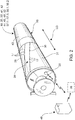
- Figure 2
- shows an example of a machine component equipped with a temperature sensor assembly as a rotating machine element, which machine element can be utilised in the invention,
- Figure 3
- shows an example of a tissue machine,
- Figure 4
- shows the example of the fibre web machine shown in
Figure 1 as a diagrammatic view in principle, and the monitoring and control system belonging to it, - Figure 5
- shows an example of information formed by means of temperature measurement,
- Figure 6
- shows an example of a sensor assembly of a machine component with temperature sensors as a cross section, for example in a temporary installation, and
- Figure 7
- shows a second example of a sensor assembly of a machine component with temperature sensors as a cross section.
-
Figure 1 shows a rough diagrammatic basic view of a fibre web machine 10'. According to an embodiment, a fibre web machine 10' may include apaper finishing section 14, but this can be implemented, at least for some parts, as a separate paper finishing machine. A sub-entity 14 now shown inFigure 1 at the end of the fibre web machine 10' when viewing it in the machine direction MD corresponds to a paper finishing machine and thus to a paper finishing section. - Generally, a fibre web machine or paper finishing machine 10' includes one or more sub-entities 11 - 15. A fibre web machine 10' may include consecutive sub-entities in the direction of travel of the fibre web W, or web for short, in other words in the machine direction MD (starting from the left edge of
Figure 1 ): headbox (not shown inFigure 1 ), web forming section 11 (more generally, forming section),press section 12, dryer section 13', possible finishingsection 14, and reel 15. Naturally, there may be other sections, too, between the sections 11 - 15. In this way, the sequence shown is not intended to limit the invention in any way. In thefinishing section 14 following the dryer section 13', such as also in a separate paper finishing machine, there can be one or more finishing devices, of whichFigure 1 shows just a sizer as an example. More generally, finishing can comprise, for example, calendering, coating, surface sizing and/or second drying shown inFigure 1 , which are just some examples of the process stages of finishing before thereel 15 that can be mentioned here. Moreover, processes related to paper finishing machines can also include unwinding, slitting-winding and/or rewinding. - One or more process stages belonging to a sub-entity 11 - 15 are performed on each sub-entity 11 - 15. The forming
section 11 is used for forming the fibre web W, thepress section 12 is used for pressing water out of the fibre web W in one or more stages, the dryer section 13' is used for drying the fibre web W, the finishingsection 14 is used for possible finishing of the fibre web W, and thereel 15 is used for reeling the fibre web W onto amachine roll 49, in other words for reeling. - At least some of the sub-entities 11 - 15 of the fibre web machine 10' contain one or
more machine components 44, examples of which are shown inFigures 1 ,3 and4 . The fibre web W is taken, or led, through sub-entity 11 - 15 via one ormore machine components 44. More generally, themachine components 44 are used for influencing the fibre web W and, on the other hand, the fibre web W also influences them. Here, influencing may mean, for example, the guiding of the travel of the fibre web W in a sub-entity 12 - 15 through the sub-entity 12 - 15. - Moreover, influencing may also mean, for example, the directing of a thermal effect on the fibre web W on the
machine component 44, via which it travels, for example to dry and/or profile the fibre web W. Themachine component 44 of the sub-entity 12 - 15 may also be such that the fibre web W influences it directly or indirectly, in other words secondarily. In this case, the heat of the fibre web W may be transferred either directly or indirectly, in other words secondarily, to themachine component 44, in which case it heats up (or cools down). This influencing is hence transfer of heat. - The influencing may also be direct. In this case, the fibre web W travels via a
machine component 44, such as a dryingcylinder 35,web lead roll 16 or reel-up drum 45, being in direct contact with it. The influencing may also be indirect, in other words secondary. In this case, the heat of the fibre web W is transferred to amachine component 44, such as to a lead roll 48' of afabric cycle fabric fabric machine component 44 to influence it. In this case, the fibre web W has influenced thefabric fabric cycle fabric 32 between the fibre web W and themachine component 44. Here, the transfer of heat from the fibre web W through thefabric 32 to themachine component 44 takes place more efficiently than in an embodiment, where the fibre web W does not travel via themachine component 44, but only thefabric 32 does that, to whichfabric 32 the heat of the fibre web W has first transferred and from which the heat is then transferred to themachine component 44. What is hence measured in this case is the temperature of thefabric fabric cycle - One or more of the
machine components 44 can berotatable machine elements 41. Some examples of rotatingmachine elements 41 are rolls andcylinders fabric cylinders fabrics fabric cycles fabric 32 can be located between the web W and themachine component 41, as is the case, for example, in thepress section 12. On the other hand, the web W can be located between thefabric 33 and themachine component 41, as is the case, for example, in the dryer section 13'. The sub-entity 14 can also be without a fabric cycle, at least in part. This is the case in the application example of the sizer 14', in other words the sub-entity 14 and also thereel 15. In this case, themachine element 41, in other words the rolls of the sizer, and a spreader roll 42 and reel-up drum 45 on thereel 15 are in direct contact with the web W. One or more of themachine elements 41 is equipped with asensor assembly 24. - There are now
rotatable machine elements 41 for example in thepress section 12. There, tworolls 67, 52 placed against each other together form a press nip 51, via which the fibre web W now travels supported on two sides byfabrics 32. There can be one or more press nips 51 in thepress section 12. - Furthermore, there are
rotatable machine elements 41 also in thedryer section 13', 13. Thedryer section 13', 13 typically includes elongated cylindrical machine components. Such machine components shown inFigure 1 are overhead dryingcylinders 35, with which the fibre web W taken via them is dried supported by afabric 33, and lower turn rolls 64, which may also be provided with vacuum. Thecylinders 35 and rolls 64 can be grouped into dryer groups. In this case, the dryer section 13' includes multiple consecutive dryer groups to perform drying. A dryer group can be a single tier or double tier dryer group. InFigure 1 , the dryer group is composed ofalternate drying cylinders 35 arranged on different levels and of vacuum rolls functioning as turn rolls 64, via which a dryingfabric 33 is adapted to travel as an endless loop while supported in order to transport and support the web W. A dryer group is defined, for example, by drying fabric cycles 23. There can also be drying implemented using a corresponding principle in the finishingsection 14 or paper finishing machine as a single or multiple unit processes, for example after surface sizing 14' and/or coating as a post-drying relating to them. There, cylinder drying can be carried out even on just one drying cylinder, which in this case in itself forms the dryer group with its fabric, which circulates in a fabric cycle arranged for it. In this case, the dryer group may even be without turn rolls. The dryer group may also be a double tier dryer group. It can generally be said that the fabric cycles 22, 23 are arranged to support and draw the web W. - The dryer section 13' of a fibre web machine 10' may also have, in addition to a mere cylinder dryer section, also one or more vertical and/or horizontal impingement dryers (not shown). These also have their own fabric cycles with fabrics. In this case, impingement drying is typically performed on the dryers at the beginning of the dryer section 13', which is then followed by more conventional cylinder drying with
heated drying cylinders 35. - The dryer section 13' can be followed by a
possible finishing section 14 in a manner known per se. The finishingsection 14 is shown inFigures 1 and4 in part only and in a rough diagrammatic view. The finishingsection 14 can include one or more handling entities, in other words process stages with their equipment, performed on the fibre web W. The handling entities can be divided further into one or more unit processes. A finishingsection 14 can be a fixed part of the machine line (online), in other words immediately after the fibre web machine 10', as shown inFigures 1 and4 , or also a separate sub-entity of its own (offline). In this case, thedryer section 13 of a fibre web machine 10', particularly of a tissue machine 10 (Figure 3 ), can be directly followed by, for example, areel 15, with which the fibre web W is formed in at least one stage into aroll 49 before its possible finishing (further processing). Naturally, there may be other sections, too, between the sub-entities. In this way, the sequence shown or the process stages performed and/or their unit processes are not intended to limit the invention in any way. The finishingsection 14 following the dryer section 13' can comprise process stages, in other words handling entities, such as various types of calendering, coating stages, surface sizing stages, and unit processes related to these - moistening, drying and/or profiling stages - which are to be mentioned in this conjunction as just some examples of the finishingsection 14 before thereel 15 or of a separate paper finishing machine. There can be one or more of the same process stages in the finishingsection 14, depending on the product manufactured by the machine in question or on the product manufactured in each individual case. Some of the process stages placed in finishing (such as some of the coating processes) can even be omitted, if the end product manufactured does not require it. - At least in some of the sub-entities 13', 13, 14, one or more process stages 39.1, 39.2 can be performed on the fibre web W. The process stages 39.1, 39.2 can include, for example, drying and/or profiling of the fibre web W as one or more unit processes belonging to the sub-entity 13', 13, 14. It is to be noted that drying, too, can be considered profiling of the fibre web W, especially in the finishing
section 14. Process equipment accomplishing drying can include, for example, dryers, which may be contact dryers, such as cylinder dryer, in other words dryer section 13'. The dryers can also be contactless, such as IR, suspended, turnfoil, induction and air dryers. Process equipment accomplishing profiling can include, for example, moistening and calendering equipment and presses. Of course, dryers can also be used for profiling the fibre web W, as was stated above. - The text that follows describes the method according to the invention for measuring the moisture of the fibre web W in a
tissue machine 10, which measurement is carried out by means of asensor assembly 24 arranged in amachine component 44 adapted in one or more sub-entities 12, 13, 15, more specifically, in arotating machine component 41, whichsensor assembly 24 is used for measuring a quantity that is proportional to the moisture of the fibre web W. In the method, in one or more sub-entities 11 - 15 of thetissue machine 10, thesensor assembly 24 arranged on theshell 31 of arotating machine element 41 and/or on thecoating 43 disposed on theshell 31 is used to measure the temperature of the fibre web W for forming a cross-directionalCD temperature profile 21 of the machine. Temperature can be measured directly from the fibre web W. Moreover or alternatively, the temperature of the fibre web W can also be measured indirectly. In this case, it can take place, for example, via afabric fabric fabric fabric fabric cycle fabric - There is a correlation between the temperature and moisture of the fibre web W. In this case, the
temperature measurement 28 of the fibre web W also gives an understanding of the moisture state of the fibre web W. Hence, in accordance with the method, the cross-directional CD moisture profile 21' of the fibre web W is established on the basis of thetemperature profile 21 established by thetemperature measurement 28 carried out. - In accordance with an embodiment, the temperature of the fibre web W is measured by means of a
sensor assembly 24, which is arranged in a non-oscillating manner, that is, in a way that does not move back and forth in the cross direction CD of the machine, in amachine component 44, particularly, in arotating machine component 41, belonging to or adaptable to a sub-entity 12 - 15, for example one shown inFigure 2 . For this, themachine component 44, more specifically, a rotatingmachine element 41, which influences the fibre web W or which is influenced by the fibre web W, directly or indirectly, is equipped with asensor assembly 24 that measures temperature. Thesensor assembly 24 includes one ormore temperature sensors 17 arranged in themachine component 44 in the cross direction CD of the machine, in other words in the longitudinal direction of themachine component 44. In other words, thesensor assembly 24 is in this case arranged to carry out the measurement primarily simultaneously in the entire cross direction CD of the machine. As compared to, for example, scanning and thus oscillating measurements, this enables the generation of up-to-date temperature information and hence moisture state information generated from it from over the primary cross direction CD of the entire machine, in other words in the lateral direction of the fibre web W. In other words, the measurement and the results derived from it can in this case also be mainly real-time. - According to an embodiment, such a
non-oscillating machine component 44 may be, as mentioned above, for example, at least one rotating orrotatable machine element 41. An example of one is shown inFigure 2 . At least in somesub-entities tissue machine 10, there may be one ormore machine elements 41 with a sensor assembly. In arotating machine element 41, thesensor assembly 24 that measures temperature may be, for example, on theshell 31 of themachine element 41 and/or in acoating 43 adapted over theshell 31. - The
sensor assembly 24 may be composed of anysensors 17 that measure temperature directly or indirectly. Thesensor assembly 24 includes one ormore temperature sensors 17. Thetemperature sensors 17 may be adapted, for example, on theshell 31 of themachine element 41 and/or under theroll coating 43, in other words on the surface of theshell 31 and/or in acoating 43 adapted over theshell 31 and/or, in some situations such as ones involving temporary measurement, also over theroll coating 43. Typically, there is one or more coating layers, more generally acoating 43, over thesensor assembly 24. Thesensor assembly 24 can hence be installed on themachine element 41 in connection with its coating, for example. While thesensor assembly 24 is under thecoating 43, in other words inside thecoating 43, like for example between coating layers, thesensor assembly 24 is protected. While like this, the temperature of the fibre web W is measured by means of thesensor assembly 24 arranged in themachine component 44 so that thesensor assembly 24 itself and the fibre web W do not touch each other, in other words they have no physical contact. In this case, thesensor assembly 24 is protected against, for example, fouling and breaking, more generally against detrimental effects outside themachine component 44. - According to an embodiment, the temperature of the fibre web W is measured by means of a
sensor assembly 24 arranged in themachine component 44 so that the transfer of heat taking place from themachine component 44 to thesensor assembly 24 is prevented, concerning, for example, heat led to themachine component 44 and/or generated in themachine component 44. The temperature of the fibre web W is hence measured by means of thesensor assembly 24, which is arranged in themachine component 44 so that the process heat brought to themachine component 44 and/or generated in themachine component 44 does not essentially influence the measurement of the temperature of the fibre web W. In this case, the heat and/or cooling generated in themachine component 44 itself / heat and/or cooling brought to it cannot influence thetemperature measurement 28 performed on it. - In addition to the prevention of the transfer of heat referred to above, it is also possible to promote the transfer of heat taking place from the
surface 50 of themachine component 41 to thesensor assembly 24, concerning the heat of the fibre web W and/or of thefabric coating 43 of themachine element 41 can be adapted to be such in terms of thesensor assembly 24 that an as good transfer of heat as possible is enabled from thesurface 50 of themachine element 41, more generally of themachine component 44, to thesensor 17. It is also advantageous that the heat of thefabric machine element 41 is transferred or the temperature is transmitted as well as possible to thesensor assembly 24. In this case, for example, thesensor assembly 24 is installed closer to theouter surface 50 of thecoating 43 than the outer surface of theroll shell 31. According to an embodiment, this can be implemented so, for example, that the installation depth of thesensor assembly 24 from theouter surface 50 of thecoating 43 is advantageously 5 - 45% of the thickness of theentire coating 43. This enables the measurement of temperature more reliably without disturbances from, for example, the potentially poorer thermal conductivity of the coating material. - Some possible examples of
temperature sensors 17 here are temperature-sensitive semiconductors, resistive sensors or thermocouples. Thesensor assembly 24 can be composed of, for example, asensor band 36 or a series of sensors formed by one or morediscrete sensors 17. - The
temperature sensor band 36 can be in themachine component 44, in other words now in therotating machine element 41 in the manner shown, for example, inFigure 2 in a spiral, in other words with a pitch, or it can also be in a straight line in the longitudinal direction of themachine element 41 or also in the circumferential direction. In this case, thesensors 17 can be disposed on theshell 31 of themachine element 41 at an even distance from each other. In this case, an area free from sensors remains between them. According to an embodiment, thesensor band 36 may even rotate around themachine element 41 in such a steep spiral that thesensor band 36 is rotated around themachine element 41 several times over. The angle of rotation of thesensors 17, more generally thesensor assembly 24, on theshell 31 of themachine element 41 may be 180 - 320 degrees, for example. When disposed in a pitched manner, thesensors 17 rotate around theshell 31 of themachine element 41 in a spiral manner at a distance from each other. The configuration of thetemperature sensor assembly 24 can hence be quite free. With a spiral installation, however, the installation of thetemperature sensor band 36 is easy, and it has the least impact on the strength of thecoating 43 of themachine element 41. However, the installation geometry of thesensor band 36 in itself is not related to the operation of thesensor 17 or to the operation of the method to be presented below in more detail. - According to an embodiment, a separate conductor may be connected to each
sensor 17 from the end of themachine element 41, or thesensors 17 may also be connected in parallel. In the embodiment shown inFigure 2 , thesensors 17 included in thesensor band 36 are advantageously connected in series. The measurement signal of thesensors 17 is read from thesensor band 36 via, for example, four conductors. In this case, no complex cabling is needed. The width of thesensor band 36 can be a few millimetres, such as 5 mm, and the length as necessary. - The
sensors 17 that measure temperature can be intelligent in themselves. A pulse, which travels through the entire series of sensors, can be fed to thesensors 17 from themeasurement electronics 40. As a result of this, eachsensor 17 responds with its temperature or corresponding measurement signal generated by it when it receives an excitation impulse from themeasurement electronics 40. In this case, the first sensor (closest to the measurement electronics 40) of thesensor band 36 may respond first, followed individually by eachsensor 17 after it until allsensors 17 have been covered. In this way, themeasurement electronics 40 may receive ameasurement signal 25, which corresponds to the temperature reading, from eachsensor 17 as sampled data. The sampled data can be used for generating, for example, thetemperature profile 21 of the fibre web W adapted to travel via the machine element 41 (Figure 5 ), whichtemperature profile 21 has a correlation with the moisture profile 21' of the fibre web W. On the basis of themeasurement data 25 generated by one ormore temperature sensors 17, more generally on the basis of thetemperature measurement 28, it is possible to generate thetemperature profile 21 of the fibre web W in the cross direction CD of the machine, whichtemperature profile 21 is used for generating the moisture profile 21' of the fibre web W in the cross direction CD of the machine. Both thetemperature profile 21 or just the moisture profile 21' can be displayed on adisplay unit 27 belonging to user interface means (Figure 4 ), and it can be used in the control of the circumstances of the sub-entity 12 - 15, one or more process stages or even a unit process in it and/or in condition monitoring or in the adjustment of the moisture state of the fibre web W. The embodiments related to the method are described in more detail in the description below. - Yet another way as compared to the pulse-connected/series-connected
sensor band 36 described above is to use even moreintelligent temperature sensors 17. In this case, eachsensor 17 may have an address of its own, for example. In this case, theelectronics 40 may always inquire the temperature from eachsensor 17 so that the sensor, from which the temperature is inquired, is identified first with its address, then thesensor 17 responds to the inquiry for the information, and then the information is transmitted along a digital bus to themeasurement electronics 40. In this configuration, the identifying address of eachsensor 17 has thereby been defined for theelectronics 40. When the location of eachsensor 17 in the machine element 41 (in its longitudinal direction, in other words in the cross direction CD of the machine) is known, it is possible to generate thelongitudinal temperature profile 21 of themachine element 41, whichlongitudinal temperature profile 21 correlates with the moisture profile 21' of the fibre web W (Figure 5 ). In a spiral installation, it is also possible to obtain the machine-directionalMD temperature profile 21 of themachine element 41, in other words thecircumferential temperature profile 21 of themachine element 41, and hence also the moisture profile 21' of the fibre web W in the circumferential direction of themachine element 41. - The
machine element 41 may be provided with data transfer means 20 known per se for thesensor assembly 24 for delivering ameasurement signal 25 generated by thesensor assembly 24 to condition monitoring included in the machine control automation 38 (Figure 4 ). This can be implemented, for example, with atransmitter 20 adapted at the end of themachine element 41, enabling wireless data transmission. It is used for sending themeasurement signal 25 to a receiver adapted outside themachine element 41, for example one included in themeasurement electronics 40. The receiver may also be provided with a transmission feature for transmitting themeasurement signal 25 and/or the cross-directional temperature profile information generated by themeasurement electronics 40 from it as early as in connection with the roll further to the machine control automation, to reception means 46 adapted therein. The receiver may function as a transmitter also towards thesensor assembly 24, as described above, when exciting thesensors 17 for collecting ameasurement signal 25 from them. If the measurement is implemented in a static machine component 44 (Figure 4 ), it is of course possible to also use wire data communications between themachine component 44 and the reception means. -
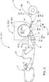
Figure 3 shows a rough diagrammatic view of an example of a fibre web machine, where the invention is utilised, now being atissue machine 10. Atissue machine 10 also includessub-entities headbox 68, formingsection 11 for forming the web W,press section 12,dryer section 13, and reel 15. The components of the press section anddryer section dryer section web forming section 11 by afabric 56, which travels in its cycle 23' arranged for it, for example via lead rolls 57.1 - 57.3 of thefabric 56 and also via press rolls 58.1, 58.2. - On the
tissue machine 10, the fibre web W is dried by means of aYankee dryer 13. Most typically, it is performed with a Yankee cylinder 35' included in aYankee dryer 13, which Yankee cylinder 35' is to be heated and can hence be considered a dryer cylinder. TheYankee cylinder 35 is adapted inside a largeenclosed hood 66. The fibre web W circulates on the surface of the Yankee dryer 35' at least via the area covered by thehood 66. The press rolls 58.1, 58.2 are placed against the Yankee dryer 35'. In this case, they together with the Yankee dryer 35' form the first and second press nips 54.1, 54.2. After the first press roll 58.1, the web W continues its travel while fastened to the surface of the Yankee dryer 35', and thefabric 56 diverges to travel via its lead roll 57.2 to return again into connection with the web W and the Yankee dryer 35' in connection with the second press roll 58.2. Hence, over the section between the press rolls 58.1, 58.2, the web W travels on the surface of the Yankee dryer 35'. The fibre web W is released from the surface of the Yankee dryer 35' on its outlet side by means of a crêping blade 53 or corresponding release device. The released fibre web W is then led via aslide shoe 62 to thereel 15, where it is formed into aroll 49 in the reel nip 69, taken via a reelingdrum 45. - A rotating
machine element 41 equipped with asensor assembly 24 that measures temperature can be, in accordance withFigures 1 ,3 and4 , for example, one ormore fabric W lead roll 16, 57.1, 57.3, for example on the press section ordryer section tissue machine 10. On thereel 15, a specific example of a fibre web W lead roll equipped with thesensor assembly 24 that can be mentioned is, for example, a fibre web W spreader roll 42. The reelingdrum 45 can be yet another individual example of arotating machine element 41 equipped with asensor assembly 24, located on thereel 15. Themachine element 41 can also be, for example, one ormore drying cylinders 35, 35' on thedryer section 13, 13' and/or on the finishingsection 14. On thepress section 12, the rotatingmachine element 41 can be, for example, one or more press rolls 52, 58.1, 58.2 that form a press nip 51, 54.1, 54.2. - Generally, a
machine component 44 equipped with asensor assembly 24 that measures temperature can be in a direct or also in an indirect, in other words secondary, heat transfer contact with the fibre web W, in other words in a contact that involves transfer of heat from the web W directly to themachine component 44 or via some component, such as via afabric machine component 44. In other words, themachine component 44 equipped with thesensor assembly 24 that measures temperature is influenced by the fibre web W directly or indirectly. The influencing involves transfer of heat. The rotatingmachine element 41 can hence be rolls andcylinders fabric fabric fabric cycle sensor assembly 24 arranged in the roll 48', 57.1 - 57.3. In this case, the web W itself does not hence necessarily need to travel via the measuring roll 48', 57.2, 57.3, but what is measured here is the temperature of thefabric fabric machine component 44 also via thefabric fabric dryer section 13, 13' or in drying by the paper finishing machine or finishingsection 14, in which case temperature can be measured from the lead roll 48' of the fabric cycle indirectly via the fabric. - The lead roll 48', 57.1 - 57.3 of the
fabric lead roll 16 of the fibre web W, for example as a grooved roll, can be an example of themachine component 44, more specifically of therotating machine element 41, inside thecoating 43 of which thesensor assembly 24 may be located. A specific advantage of a grooved roll is, for example, the elimination of the boundary-layer air between the fibre web W and the roll surface. Thesensor assembly 24 adapted to measure temperature enables the arrangement of the sensor assembly also on a grooved roll, because in this case it can be arranged inside the roll structures, such as in its coating or under it. - A roll or other corresponding
rotating machine element 41 is an advantageous way of implementingtemperature measurement 28 and also the measurement of thetemperature profile 21 generated by it in order to generate moisture state information on the fibre web W, because it rotates at the speed of the fibre web W (unlike, for example, a static beam). Moreover, a rotatingmachine element 41 can also be grooved, in other words the measurement is carried out on a grooved roll or, more generally, on a rotating machine element. In this case, boundary-layer air can be minimised. As a result of this, the transfer of heat from the web W to therotating machine element 41 can be made to be as good as possible, when the contact between the web W and therotating machine element 41 is good. According to an embodiment, themachine component 44 can also be essentially unheated. Hence, no external heat, for example, is brought to it. In this case, its temperature is primarily influenced only by the temperature of the fibre web W and/orfabric machine component 44. - When implemented with the above-mentioned technology integrated into the
machine component 44, the temperature measurement and the measurement of thetemperature profile 21 generated by thetemperature measurement 28 and the generation of the moisture state information and moisture profile 21' from it is advantageous to implement. In this case, themeasurement 28 can be placed in sub-entity 12 - 15 even in several different points. Thesensor assembly 24 can withstand temperatures in excess of 125°C, even 150°C and even above it. In practice, thesensor assembly 24 can be manufactured under any rubber, PU, composite or polymer coating. The implementation cost of the measurement arrangement for asingle machine component 44 is in practice the cost of thesensor assembly 24 and theroll coating 43. Since the cost remains reasonable, it is hence possible to install on a sub-entity 12 - 15 evenmultiple machine components 44 that performtemperature measurements 28, for example in the form of rotatingmachine elements 41 or static beams 61 in order to determine and/or conclude, more generally, to generate moisture state information and/or moisture profile 21' from the temperature information andtemperature profile 21. - As referred to above, the measurement arrangement does not necessarily require a
rotating machine element 41, in other words a roll or cylinder, in which case other types of solutions for the arrangement of the measurement are also possible. Amachine component 44 equipped with asensor assembly 24 that measures temperature can also be a static, in other words stationary, non-rotating/immobile machine structure 60, as shown inFigures 3 and4 , for example. Thestatic machine structure 60 equipped with thesensor assembly 24 that measures temperature can be, for example, a beam 61 arranged to carry out the measurement and being in contact with the web W (does not need to a scanning beam), aslide shoe 62 and/or a crêping blade 53 adapted into contact with the fibre web W and/or fabric. It is characteristic of the measuringstatic machine structure 60 that it is located sufficiently close with respect to the fibre web W in order to indicate essential temperature information on, for example, the pocket in question. - The
temperature measurement 28 and the generation of thetemperature profile 21 from it, whichtemperature profile 21 is proportional to the moisture state and moisture profile 21', can be carried out by measuring temperature, for example, at set time intervals, for example automatically. - The method for the monitoring and control of the operating circumstances of a fibre web machine or paper finishing machine is described below in more detail as an exemplifying embodiment referring to
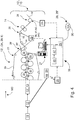
Figure 4. Figure 4 shows a fibre web machine 10' andmachine control automation 38 with condition monitoring connected to it. Instead of the fibre web machine 10',Figure 4 could equally illustrate thetissue machine 10 shown inFigure 3 . The moisture state of the web W is monitored and controlled by means of one ormore machine elements 41 and/orstatic machine structures 60 that belong to the machine and that are, for example, rotatable in it. Theshell 31 and/orcoating 43 of themachine element 41 and/ormachine structure 60 contains asensor assembly 24 that measures temperature in the manner shown, for example, inFigure 2 . - The
machine element 41 equipped with thesensor assembly 24 that measures temperature is rotated when performing production. Ameasurement signal 25 is generated by thesensor assembly 24 arranged in themachine element 41 from the temperature of themachine element 41, to which temperature themeasurement signal 25 generated by thesensor assembly 24 is proportional. This temperature can vary in the cross direction (CD) of the machine, in other words in the longitudinal direction of themachine element 41 and/or even themachine structure 60. Themeasurement signal 25 generated by thesensor assembly 24 can be saved. Across-directional temperature profile 21 of themachine element 41 and/or themachine structure 60, for example, is generated from themeasurement signal 25, and the moisture profile 21' of the fibre web can be generated further from this. - According to an embodiment, drying of the fibre web W in the cross direction CD of the machine and/or profiling of the fibre web W is controlled based on the moisture profile 21' generated based on the
temperature measurement 28, for example, specifically in terms of the moisture state and moisture profile 21', hence influencing the dry matter content and/or moisture level of the fibre web W. The moisture profile 21' in particular indicates how even the cross-directional drying of the machine is. The control takes place by influencing the process stages and/or machine components, in other words by adjusting them. More specifically, one or more of the following, for example, are controlled in profiling:steam box 65 of the press section 12 (Figure 1 ), damper, profiling dryer 34 (such as profiling infra/suspended), such as profiling of the Yankee cylinder 35' and/or thehood 66 of the Yankee cylinder 35' and/or the press nip 51, 54.1, 54.2 in order to adjust the cross-directional CD moisture profile 21' of the fibre web W. Moisture profile measurement based on thetemperature profile 21 can also be implemented as part of automatic profile adjustment, for example, in connection with the above-mentioned devices. - The temperature of the fibre web W can be measured on one or more sub-entities 11 - 15 in connection with at least one process stage 39.1, 39.2 in at least one point, but advantageously this can also be carried out in two or even more points. Advantageously, the temperature of the fibre web W can be measured before the process stage 39.1, 39.2, after the process stage 39.1, 39.2 and/or within the process stage 39.1, 39.2.
- The arrangement of the measurement in multiple machine-directional MD positions enables exactly, for its part, that the
sensor assembly 24 has been arranged and is arranged in amachine component 44 that is already included in / will be included in / belongs to the machine, whichmachine component 44 has a primary purpose other than temperature measurement. In this way, thesensor assembly 24 does not, at least as a fixed installation, necessarily require the arrangement of a specific machine component of its own in the machine for thetemperature measurement 28, the adaptation of which in the machine might be particularly challenging due to, for example, the limited space in the layout. This is a prevailing condition particularly intissue machines 10. When the temperature of the fibre web W is measured in the machine direction MD by means of thesensor assembly 24 arranged inmultiple machine components 44, it is also possible to monitor the trend of the moisture profile 21' of the fibre web W in the machine direction MD. In this case, the machine-directional MD moisture level of the fibre web W can be approximated on the basis of thetemperature measurement 28, and the drying capacity can be adjusted on its basis, also as a whole. - A
machine component 44 arranged for the generation of thecross-directional temperature profile 21 in exact the cross direction CD of the machine is particularly advantageous, because as a component already existing in the machine and being a component that belongs to the production environment in another primary purpose, it does not require any additional components specifically for temperature measurement and for the generation of moisture information from it, the arrangement of which might even be impossible due to, for example, the limited space of the cycle. In this way, the temperature measurement performed in themachine component 44 and now arranged in the machine as a fixed installation can be referred to as a secondary function of themachine component 44, which secondary function is arranged in it in addition to the actual function intended to be performed by it (such as guiding of web or fabric, drying or sizing / surface sizing). Thetemperature measurement 28 for the generation of moisture information 21' can take place as a cross-directional profile measurement or also as an individual value measurement. The temperature measurement and temperature profile measurement of the web W and the moisture state information generated from it enable, for example, a better monitoring and adjustment performed on its basis of the drying of the web W and/or its finishing measures. - In addition to measurement taking place at the dry end, the result can be made more accurate by adding measurements at the wet end / before drying or within drying. As an example, temperature can be measured on the
tissue machine 10 shown inFigure 3 on one or more of the following: on thepress section 12 on one ormore fabric 56 lead rolls 57.1 - 57.3, inside thehood 66 of the Yankee drum 35', in the area of the crêping blade 53 and on the lead roll or slideshoe 62 of the fibre web W and/or on the reel-up drum 45. This gives an understanding of the trend of thetemperature profile 21 and consequently a sufficient approximation also of the trend of the moisture profile 21'. The measurement can also be used for observing thetemperature profile 21 of the Yankee drum 35' at multiple points of drying inside thehood 66. In principle, the measurement can also be placed inside the Yankee drum 35'. - According to yet another embodiment, it is possible to use the
temperature measurement 28 to establish a nip force profile or nippressure profile 55 of the press nip 51, 54.1, 54.2 in the cross direction CD of the machine as a quantity that is proportional to the moisture of the fibre web W. Theprofile 55 can also be mainly real-time. It is also shown inFigure 5 . On the basis of thetemperature measurement 28, it is possible to adjust the nip force profile or nippressure profile 55 of the press nip 51, 54.1, 54.2. Especially ontissue machines 10, the profile of the press nip 54.1, 54.2 can be seen well in thetemperature profile 21, because, for example, edges loaded with too small a nip load remain more moist due to poor dewatering, and furthermore the contact with the surface of the Yankee drum 35' remains poor. Temperature profile measurement hence also gives an indication of the functioning of drying, and it can be used for improving the nip profiles and for the condition monitoring of the press. - A temperature profile sensor assembly installed on the
rotating lead roll fabric cylinder 35, 35' or on therotating machine element 41 of some process device is used for monitoring, for example primarily continuously, their temperature and/or atemperature profile 21 that is generated from it and that is proportional to the moisture state. In this way, it is possible monitor the moisture state of the fibre web W that travels via themachine component 44, which moisture state is influenced by the temperature impact caused on the fibre web at some point of the production process, which temperature impact has been accomplished by means of, for example, the drying devices and/or profiling devices of the fibre web W, such as cylinder dryer, induction device, air device or infrared device. A sensor spacing of, for example, 50 mm can be used in the cross direction CD. This indicates accurately the cross-directional CD temperature profile and consequently also the moisture profile 21' that is proportional to it. As a result of the invention, it is possible to control drying, for example, to accomplish and secure sufficient drying of the fibre web W, advantageously without excessive over-drying. More specifically, it is possible to control very accurately and advantageously automatically, for example, induction, IR, air, suspended or turnfoil dryers, which potentially also have a profiling impact on the fibre web W. As a result of the measurement and the control carried out on its basis, it is possible, for example, to optimise the functioning of the dryers and to also achieve their energy savings. By using the information generated in the measurement, for example profiling, such as the control of dampers, is also possible in order to adjust the cross-directional CD profile of the fibre web W in the desired manner. - According to an embodiment, it is also possible to directly measure the moisture profile 21' of the fibre web W in at least one point of the sub-entity 13', 13. The measurement can be carried out using a scanner after the
dryer section 13', 13, for example. The moisture profile obtained from this measurement can be used as the final reference of the moisture profile. In this case, based on the measured moisture profile of the fibre web W and on one or more temperature measurements /temperature profile measurements 28 performed in various positions of the sub-entity 13', 13, it is possible to make the generation of the moisture level and/or moisture profile of the fibre web W based on thetemperature measurement 28 more accurate in one or more points of drying 39.1, 39.2 and/or profiling throughout thedryer section 13, 13' or drying 39.1, 39.2 or even theentire sub-entity 13, 13'. To make this more accurate, it is also possible to use moisture profile measurement on thepress section 12 or a temperature measurement arrangement placed on thepress section 12, if ones are available. - According to an embodiment, when the temperature of each point and the moisture state generated from it are known, it is possible to control the functioning of the drying
cylinders 35, 35', dryers 34 (such as impingement, suspended, turnfoil, IR and/or induction dryers) and/or profiling devices and/or dampers on the basis of the temperature information and moisture state information in order to control drying 39.1, 39.2 and/or the profiling of the fibre web W performed on them, in particular on dampers. In this case, it is possible to adjust and optimise the functioning of the drying means 34, and also to profile dampers. It is also possible to include profiling opportunities located before the dryer section 13' in the adjustment, such as asteam box 65 of thepress section 12. -
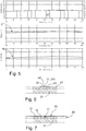
Figure 5 , in turn, shows an example of information generated by means oftemperature measurement 28. The figure shows thecross-directional temperature profile 21 measured by means of asensor assembly 24 arranged in amachine element 41. A person having ordinary skill in the art understands that in reality the shape of theprofile 21 can vary greatly from this. There is a location axis in the horizontal direction, in other words locations on theshell 31 of themachine element 41 in the cross direction CD of the machine, and a temperature axis in the vertical direction in Fahrenheit units. The middlemost graph, in turn, shows the moisture profile 21' generated on the basis of thetemperature measurement 28. The bottom graph, in turn, shows the primarily real-time nip force profile or nippressure profile 55 of the press nip 51, 54.1, 54.2 in the cross-direction CD of the machine, generated from the moisture profile 21' and hence from thetemperature profile 21. Such information can be presented, for example, on thedisplay unit 27 of the machine control system to the operators. - In addition to the method, the invention equally also relates to a system for measuring the moisture of the fibre web W in a
tissue machine 10. The machine includes one or more sub-entities 11 - 13, 15, each of which has been adapted to perform one or more process stages 39.2 belonging to a sub-entity 11 - 13, 15. The process stages 39.2 can include, for example, drying and/or profiling of the fibre web W as one or more unit processes. The fibre web W is adapted to be taken through a sub-entity 11 - 13, 15 via one ormore machine components 44, more specifically, a rotatingmachine element 41. One or more of themachine elements 41 is equipped with asensor assembly 24. Asensor assembly 24 arranged in amachine component 44 adapted in one or more sub-entities 12, 13, 15, more specifically, in arotating machine element 41, is adapted to measure a quantity that is proportional to the moisture of the fibre web W. The moisture state of the fibre web W is adapted to be generated from the quantity measured by processingmeans 47. In the system, on one or more sub-entities 11 - 15 thesensor assembly 24 is adapted to measure the temperature of the fibre web W, directly or indirectly. Moreover, the processing means 47 are adapted to establish the moisture profile 21' of the fibre web W in the cross-direction CD of the machine on the basis of thetemperature profile 21 generated by thetemperature measurement 28. The system is adapted to implement one or more of the sub-stages of the above-described method, implemented by means of, for example, asensor assembly 24 and a computer. Machine control also includes memory means 26, for example for saving the measurements and the information generated from them, and user interface means, comprising adisplay unit 27, for example for viewing the measurements and the information generated from them. - In addition to the method and system, the invention also relates to a
rotating machine element 41. It includes ashell 31, acoating 43 arranged over theshell 31 and asensor assembly 24 installed, for example, in a spiral manner under or inside thecoating 43 and adapted to measure temperature. Themachine element 41 is used in the above-described method or system to determine and/or conclude the moisture state of the fibre web W on atissue machine 10 on the basis of atemperature measurement 28 arranged in themachine element 41 and atemperature profile 21 generated based on the measurement. - The invention enables the online determination/approximation of the moisture state from
temperature profiles 21 at different points of the sub-assembly 12 - 15 and advantageously even throughout the sub-entity 12 - 15. The invention also enables automatic adjustment of dry matter content / moisture as well as optimal control of drying and profiling. The invention can be implemented as an original installation or also as a retrofit product for a sub-entity 12 - 15 or process stage 39.1, 39.2. The invention enables the replacement of dangerous temporary measurements, which are used, for example, in the analyses and optimisation ofdryer sections 13, 13'. The invention can also be implemented by way of a temporary installation, as will be described more specifically below. In this case, the temporary measurement can be installed at a desired point during a shut-down, and the production information resulting from it can be used during production for analysis. - In addition to the method and system, the invention also relates to a computer program product 29 (
Figure 4 ) for measuring the moisture of the fibre web W in atissue machine 10. The computer program product 29, which may be, for example, in a suitable storage medium or also downloadable over a data network or available as a service product, contains software code means 30 that implement the computer program logic stored in a storage medium 29' that is readable by acomputer 27. The software code means 30 are arranged to carry out the stages of the method according to the invention for measuring the moisture of the fibre web W on the basis of atemperature profile 21 established by atemperature measurement 28 taken on one or more sub-entities 12, 13, 15 of atissue machine 10, when the computer program is run in thecomputer 27. - The methods, systems and computer program logics 30 according to the invention can be arranged, for example, as part of the machine control and
production control automation 38 and/or condition monitoring belonging to it. The operations according to the invention, in other words measuring, monitoring and control, are performed advantageously automatically and primarily continuously. Yet another additional advantage is that the system is learning. - What was presented above extensively were measurement arrangement examples, which are carried out, for example, in a
rotating machine element 41 by means of asensor assembly 24 most typically installed under or inside acoating 43. This requires the coating of an existing roll or cylinder or even anew machine element 41. In this case, amachine element 41 in the machine must be replaced with a coated one. This takes time, and in some positions the replacement of the roll or cylinder may be an arduous task. Thecoating 43 also has a cost, and it is furthermore necessary to wait for its manufacture. It is not even possible to install a coated roll in many positions, for example due to doctoring. - The
sensor assembly 24 can be arranged in amachine component 44, such as a rotatingmachine element 41, also as a temporary installation. The advantage of asensor assembly 24 installed temporarily is its flexibility. Thesensor assembly 24 can be installed on a roll in the machine during a shut-down, and the measurements can be performed after it while the machine is operating. In a temporary installation to thesurface 50 of amachine element 41, thesensor 17 senses the web W orfabric surface 50 of themachine element 41 quickly, because it is on thesurface 50 of themachine element 41, and there are no thermally-insulating coating layers 43 over it. On the other hand, also, when production and hence also the temporary measurement have started, themachine element 41 itself warms up relatively slowly, if it even is of a type heated/heating in the process. It therefore takes its own time before its potential heating effect extends to itssurface 50. In this case, the heat caused by themachine element 41 / heat brought / generated in it does not have time to influence itssurface 50 and hence thesensor 17 arranged in it. In this case, a measurement performed from thesurface 50 of themachine element 41 corresponds very well to the temperature of the web W and/orfabric - The
sensor assembly 24 can be installed during a shut-down on, for example, aweb lead roll 16, and then the measurements can be performed during operation. In this case, it is possible to analyse the temperatures and temperature profiles of the web W, adjust the dryers 39.1, 39.2, collect data for models (such as DryMan) and/or also optimise the operation of other profiling devices (such as damper, thermorolls of the calender, or profiling dryers). The measurements and the analysis of the results can be carried out as a service flexibly and cost-efficiently, without waiting for issues such as coating of rolls or equipment installation. Solutions and applications described above in the description can in particular be provided as a service. - Instead of a
rotating machine element 41, a temporarily-installedsensor assembly 24 can also be implemented by means of a temporarily-installed beam, which has atemperature sensor band 36. The beam is pushed into the machine to a desired location into contact with the web W orfabric - In addition to the
dryer section 13, 13' or finishingsection 14, the temporary measurement can also be carried out at the wet end of the fibre web machine on thelead roll 48, 48' of the fabric such as a wire or press felt. -
Figure 6 shows an example of atemporary sensor assembly 24 of amachine component 44 withtemperature sensors 17 as a cross section. Even in a temporary installation, thesensor assembly 24 can be installed on, for example, theweb lead roll 16, again in a spiral manner, on itssurface 50 for temporary measurement. In this case, it withstands best, and moreover any disturbances to the travel of the web W are minimal. Thesensor band 36 can be, for example, of 5 mm wide polyimide band. It containssensor components 17 at desired intervals, such as at intervals of 50 mm. In this way, a high-resolution temperature profile measurement is obtained for analyses. If the height of thesensor component 17 so requires, an adjusting tape 59' can be installed around it. It levels out the environment of thesensor component 17 so that thecomponent 17 does not puncture or mark the web W travelling via theroll 16. A protectingtape 63 can also be installed over theentire sensor assembly 24. This can be, for example, a Teflon or metallic tape. More generally, thesensor assembly 24 is adapted on thesurface 50 of themachine element 41, and a material layer, more generally afiller 59, which is wider than thetemperature sensor 17 and which levels out thesurface 50 of themachine element 41, is adapted in connection with thetemperature sensors 17 belonging to thesensor assembly 24, now around them, in order to level out thesurface 50 of themachine element 41, in other words to create a smaller surface pressure from the point of thetemperature sensors 17 to an item being in contact with themachine element 41, such as to the fibre web W. -
Figure 7 shows yet another example of thesensor assembly 24 of themachine component 44, shown for example inFigure 2 , withtemperature sensors 17 as a cross section. Underneath thesensor assembly 24, there is one ormore layers 18, which insulate, at least to some extent, thesensor assembly 24 thermally from theshell 31 of the roll. As a result of thelayer 18 adapted to insulate heat, in other words to prevent transfer of heat, the heat brought to the inside of themachine component 44 and/or the heat generated in it does not disturb the temperature measurement of the fibre web W performed from the direction of the surface of themachine component 44. - Over the
sensor assembly 24, there is, in turn, one or moresuch layers 19 that conduct heat as well as possible. In this case, heat is transferred from the web W efficiently to thesensors 17. If thecoating 43 is, for example, of a single material, thelayer 19 over thesensor 17 is then thinner than thelayer 18 underneath it over the surface of theshell 31 of themachine element 41. In this way, by arranging thesensor assembly 24 in thecoating 43, the resolution capability and speed of the measurement can be made to be the best possible, and it is possible to measure the profile of the web W, and the roll does not level out the result too much in the cross direction. More generally, thelayer 18 is adapted underneath thesensor assembly 24, which is adapted to measure temperature, in order to insulate thesensor assembly 24 thermally from theshell 31 of therotating machine element 41. Moreover, thelayer 19 is adapted over thesensor assembly 24, adapted to conduct heat to thesensor assembly 24 from thesurface 50 of themachine element 41. Thesensor assembly 24 can be made in connection with, for example, roll coatings. - Regarding
tissue machines 10, further processing machines can be mentioned as a special example of further processing. With these, smaller product rolls suitable for consumer and institutional use are typically formed out of a big machine reel. Further processing operations may include, for example, surface treatment (such as printing), unwinding, web layering lines, embossing, perforating, slitting, wind-up and/or sheeting. End products made of paper W produced with a tissue machine may be intended for household or institutional use. For example, they can be hygienic papers. Some examples include household, toilet and handkerchief papers, napkins and paper towels, cleansing tissue and industrial towels. Typically, they are consumer rolls or sheets, for example. - It is to be understood that the above description and the related figures are only intended to illustrate the present invention. The invention is hence not only restricted to the above-presented embodiments or to the embodiments defined in the claims, but several different variations and adaptations of the invention will also be obvious to a person having ordinary skill in the art, which variations and adaptations are possible within the inventive idea defined by the enclosed claims.
Claims (17)
- A method for measuring the moisture of a fibre web in a tissue machine, which includes, as sub-entities, a forming section (11), a press section (12), a Yankee dryer (13) and a reel (15), each of which performs one or more process stages (39.2) included in a sub-entity (11 - 13, 15) and where the fibre web (W) is taken through a sub-entity (11 - 13, 15) via one or more rotating machine elements (41), of which one or more are equipped with a sensor assembly (24), characterised in that, in the method, in one or more sub-entities (11 - 13, 15) of the tissue machine (10)- a sensor assembly (24) arranged on the coating (43) disposed on the shell (31) and/or over the shell (31) of a rotating machine element (41) is used to measure the temperature of the fibre web (W) directly and/or indirectly for generating a temperature profile (21) in the cross direction (CD) of the machine,- a moisture profile (21') in the cross direction (CD) of the machine is formed for the fibre web (W) based on the temperature profile (21).
- A method according to claim 1, characterised in that the temperature of the fibre web (W) is measured with a sensor assembly (24) arranged in a rotating machine element (41) in such a way that the sensor assembly (24) and the fibre web (W) are disposed in a contactless manner relative to each other.
- A method according to claim 1 or 2, characterised in that the temperature of the fibre web (W) is measured with a sensor assembly (24) arranged in a rotating machine element (41) in such a way that- heat transfer from the rotating machine element (41) to the sensor assembly (24) is prevented relating to heat transferred to the rotating machine element (41) and/or heat generating in the rotating machine element (41),- heat transfer from the surface (50) of the rotating machine element (41) to the sensor assembly (24) is advanced relating to heat of the fibre web (W) and/or the fabric (32, 33, 56).
- A method according to any one of the claims 1 - 3, characterised in that the rotating machine element (41) equipped with a sensor assembly (24) for measuring temperature is one or more of the following:- a lead roll (48, 57.1 - 57.3, 16) of the fabric (32, 33, 56) and/or the fibre web (W),- a spreader roll (42) of the fibre web (W),- a Yankee cylinder (35') of a Yankee drier (13),- a press roll (52, 58.1, 58.2) forming a press nip (51, 54.1, 54.2),- a reeling drum (45).
- A method according to any one of the claims 1 to 4, characterised in that the rotating machine element (41) is essentially unheated.
- A method according to any one of the claims 1 - 5, characterised in that- based on the temperature measurement (28), a nip force profile or nip pressure profile (55) of the press nip (51, 54.1, 54.2) in the cross direction (CD) of the machine is formed as a quantity that is proportional to the moisture of the fibre web (W),- on the basis of the temperature measurement (28), the nip force profile or nip pressure profile (55) of the press nip (51, 54.1, 54.2) is adjusted.
- A method according to any one of the claims 1 - 6, characterised in that temperature is measured in one or more sub-entities (11 - 13, 15) in connection with at least one process stage (39.2) in two or more points advantageously before the process stage (39.2), after the process stage (39.2) and/or within the process stage (39.2).
- A method according to any one of the claims 1 - 7, characterised in that the temperature of the fibre web (W) in the machine direction (MD) is measured by means of the sensor assembly (24) arranged in multiple rotating machine elements (41) in order to monitor the trend of the moisture profile (21') of the fibre web (W) in the machine direction (MD).
- A method according to any one of the claims 1 - 8, characterised in that on the basis of the moisture profile (21') generated by the temperature measurement (28), the following items of the fibre web (W) are controlled in the cross direction (CD) of the machine:- drying and/or- profiling, where, for example, one or more of the following are controlled: steam box (65), damper, profiling dryer (34), such as, for example, profiling of a Yankee cylinder (35') and/or a hood (66) of a Yankee cylinder (35') and/or the press nip (51, 54.1, 54.2) in order to adjust the cross-directional (CD) moisture profile (21') of the fibre web (W).
- A method according to any one of the claims 1 - 9, characterised in that the machine-directional (MD) moisture state of the fibre web (W) is approximated on the basis of the temperature measurement (28), and on its basis, the drying capacity is adjusted as a whole.
- A method according to any one of claims 1 - 10, characterised in that the sensor assembly (24) is arranged on the surface (50) of the rotating machine element (41) for a temporary measurement.
- A system for measuring the moisture of a fibre web in a tissue machine, which includes, as sub-entities, a forming section (11), a press section (12), a Yankee dryer (13) and a reel (15), each of which performs one or more process stages (39.2) included in a sub-entity (11 - 13, 15) and where the fibre web (W) is arranged to be taken through a sub-entity (11- 13, 15) via one or more rotating machine elements (41), of which one or more are equipped with a sensor assembly (24), characterised in that, in the system, in one or more sub-entities (11 - 13, 15) of the tissue machine (10)- by means of a sensor assembly (24) disposed on the coating (43) arranged on the shell (31) and/or over the shell (31) of one or more rotating machine elements (41) is arranged to be measured the temperature of the fibre web (W) directly and/or indirectly for establishing the temperature profile (21) in the cross direction (CD) of the machine,- on the basis of the temperature profile (21) by means of processing means (47) are adapted to be established a moisture profile (21') of the fibre web (W) in the cross direction (CD) of the machine.
- A system according to claim 12, characterised in that the system is arranged to execute the sub-stages of the method according to one or more claims 2 - 11.
- A rotating machine element, which includes:- a shell (31),- a coating (43) arranged over the shell (31) and a temperature sensor assembly (24) installed under or inside the coating (43),characterised in that the machine element (41) is used in the method according to claim 1 or in the system according to claim 12 to determine and/or conclude the moisture state of the fibre web (W) on a tissue machine (10).
- A machine element according to claim 14, characterised in that:- a layer (18) is adapted under the sensor assembly (24) for preventing transfer of heat to the sensor assembly (24) from the shell (31) of the rotating machine element (41),- a layer (19) is adapted over the sensor assembly (24) for preventing transfer of heat to the sensor assembly (24) from the surface (50) of the machine element (41).
- A machine element according to claim 14 or 15, characterised in that the sensor assembly (24) is adapted to the surface (50) of the machine element (41), and a filler (59), which is wider than the temperature sensor (17), is adapted in connection with the temperature sensors (17) belonging to the sensor assembly (24) for levelling out the surface (50) of the machine element (41) at the location of the temperature sensors (17).
- A computer program product for measuring the moisture of a fibre web in a tissue machine, characterised in that it comprises software code means (30) stored in a storage medium (29') readable by a computer (27), which software code means (30) are arranged to execute all of the stages of the method defined in any one of the claims 1 - 11, when the computer program is run in the computer (27).
Applications Claiming Priority (1)
| Application Number | Priority Date | Filing Date | Title |
|---|---|---|---|
| FI20185902A FI129914B (en) | 2018-10-26 | 2018-10-26 | Method, system, rotating machine element and computer program product for measuring the moisture of a web in a tissue machine |
Publications (1)
| Publication Number | Publication Date |
|---|---|
| EP3647491A1 true EP3647491A1 (en) | 2020-05-06 |
Family
ID=69063581
Family Applications (1)
| Application Number | Title | Priority Date | Filing Date |
|---|---|---|---|
| EP19205543.2A Pending EP3647491A1 (en) | 2018-10-26 | 2019-10-28 | Method, system, rotating machine element and computer program product for measuring the moisture of a fibre web in a tissue machine |
Country Status (2)
| Country | Link |
|---|---|
| EP (1) | EP3647491A1 (en) |
| FI (1) | FI129914B (en) |
Cited By (5)
| Publication number | Priority date | Publication date | Assignee | Title |
|---|---|---|---|---|
| US20200385927A1 (en) * | 2017-11-27 | 2020-12-10 | Voith Patent Gmbh | Method for determining the dryness of a fibrous web, and method for controlling or regulating a machine for producing a paper web, and computer program for carrying out the methods |
| WO2022047139A1 (en) * | 2020-08-27 | 2022-03-03 | Buckman Laboratories International, Inc. | Predictive control of yankee dryer chemistry and creped product quality |
| SE2230438A1 (en) * | 2022-12-21 | 2024-06-22 | Valmet Oy | A paper machine |
| SE2350122A1 (en) * | 2023-02-10 | 2024-08-11 | Valmet Oy | Moisture control device, moisture control system, and method for controlling moisture of a paper web or a fabric in a fibrous web manufacturing machine |
| KR102703941B1 (en) * | 2024-07-10 | 2024-09-06 | 주식회사 아진피앤피 | Papermaking equipment and processes that enhance strength and shape retention |
Citations (5)
| Publication number | Priority date | Publication date | Assignee | Title |
|---|---|---|---|---|
| WO1999051811A2 (en) | 1998-04-06 | 1999-10-14 | Honeywell-Measurex Corporation | Water weight sensor array imbedded in a sheetmaking machine roll |
| US20020189775A1 (en) * | 2000-06-28 | 2002-12-19 | Metso Paper Karlstad Ab | Measuring arrangements in a shortened dry end of a tissue machine |
| US20050098289A1 (en) * | 2003-10-03 | 2005-05-12 | Tatu Pitkanen | Measurement method and apparatus in the manufacture of paper or paperboard |
| DE102012203035A1 (en) * | 2012-02-28 | 2013-08-29 | Voith Patent Gmbh | Machine for producing a fibrous web |
| US9284686B1 (en) * | 2014-10-30 | 2016-03-15 | The Procter & Gamble Company | Process to improve the convertability of parent rolls |
-
2018
- 2018-10-26 FI FI20185902A patent/FI129914B/en active IP Right Grant
-
2019
- 2019-10-28 EP EP19205543.2A patent/EP3647491A1/en active Pending
Patent Citations (5)
| Publication number | Priority date | Publication date | Assignee | Title |
|---|---|---|---|---|
| WO1999051811A2 (en) | 1998-04-06 | 1999-10-14 | Honeywell-Measurex Corporation | Water weight sensor array imbedded in a sheetmaking machine roll |
| US20020189775A1 (en) * | 2000-06-28 | 2002-12-19 | Metso Paper Karlstad Ab | Measuring arrangements in a shortened dry end of a tissue machine |
| US20050098289A1 (en) * | 2003-10-03 | 2005-05-12 | Tatu Pitkanen | Measurement method and apparatus in the manufacture of paper or paperboard |
| DE102012203035A1 (en) * | 2012-02-28 | 2013-08-29 | Voith Patent Gmbh | Machine for producing a fibrous web |
| US9284686B1 (en) * | 2014-10-30 | 2016-03-15 | The Procter & Gamble Company | Process to improve the convertability of parent rolls |
Cited By (9)
| Publication number | Priority date | Publication date | Assignee | Title |
|---|---|---|---|---|
| US20200385927A1 (en) * | 2017-11-27 | 2020-12-10 | Voith Patent Gmbh | Method for determining the dryness of a fibrous web, and method for controlling or regulating a machine for producing a paper web, and computer program for carrying out the methods |
| US11926963B2 (en) * | 2017-11-27 | 2024-03-12 | Voith Patent Gmbh | Method for determining the dryness of a fibrous web, and method for controlling or regulating a machine for producing a paper web, and computer program for carrying out the methods |
| WO2022047139A1 (en) * | 2020-08-27 | 2022-03-03 | Buckman Laboratories International, Inc. | Predictive control of yankee dryer chemistry and creped product quality |
| CN116075613A (en) * | 2020-08-27 | 2023-05-05 | 巴克曼实验室国际公司 | Predictive Control of Yankee Dryer Chemistry and Creping Product Quality |
| US11707906B2 (en) | 2020-08-27 | 2023-07-25 | Buckman Laboratories International, Inc. | Predictive control of Yankee dryer chemistry and creped product quality |
| SE2230438A1 (en) * | 2022-12-21 | 2024-06-22 | Valmet Oy | A paper machine |
| SE547468C2 (en) * | 2022-12-21 | 2025-09-30 | Valmet Oy | A paper machine for producing structured tissue and a method for controlling such a paper machine |
| SE2350122A1 (en) * | 2023-02-10 | 2024-08-11 | Valmet Oy | Moisture control device, moisture control system, and method for controlling moisture of a paper web or a fabric in a fibrous web manufacturing machine |
| KR102703941B1 (en) * | 2024-07-10 | 2024-09-06 | 주식회사 아진피앤피 | Papermaking equipment and processes that enhance strength and shape retention |
Also Published As
| Publication number | Publication date |
|---|---|
| FI129914B (en) | 2022-10-31 |
| FI20185902A1 (en) | 2020-04-27 |
Similar Documents
| Publication | Publication Date | Title |
|---|---|---|
| EP3647491A1 (en) | Method, system, rotating machine element and computer program product for measuring the moisture of a fibre web in a tissue machine | |
| US5377428A (en) | Temperature sensing dryer profile control | |
| EP2572038B1 (en) | Apparatus and method for controlling curling potential of paper, paperboard, or other product during manufacture | |
| CA2327792C (en) | Water weight sensor array imbedded in a sheetmaking machine roll | |
| EP2072673B1 (en) | Belt assembly and paper- or board making machine comprising the belt assembly | |
| US10697119B2 (en) | Method for monitoring a Yankee cylinder using a graphical representation of a treatment effect | |
| US8510070B2 (en) | Non-contacting temperature profile measurement of rotating rolls | |
| JPH01229891A (en) | Method for adjusting, controlling and/or monitoring coating and drying of web | |
| WO2013082696A1 (en) | Multi-source sensor for online characterization web products and related system and method | |
| US7249424B2 (en) | Method and device for controlling the moisture or coating quantity profile in a paper web | |
| CN110567738B (en) | Method, system and program for monitoring the operation of a web or sheet finishing machine | |
| US6712937B1 (en) | Method of operating a machine for the manufacture and/or refinement of material webs | |
| US11926963B2 (en) | Method for determining the dryness of a fibrous web, and method for controlling or regulating a machine for producing a paper web, and computer program for carrying out the methods | |
| US6749888B2 (en) | Method and apparatus for determining the profile of a coating layer | |
| EP1342839B1 (en) | Method and apparatus for measuring the hardness or compactness of a clothing | |
| FI128944B (en) | Method, system and computer program product for monitoring and/or controlling the conditions in a subsystem of a fiber web or finishing machine | |
| EP4491794A2 (en) | Roll weight system for on machine dynamic verification | |
| Ekvall et al. | Improved web break strategy using a new approach for steam pressure control in paper machines | |
| FI117343B (en) | A method and system for preventing vibration | |
| WO2024132474A1 (en) | A paper machine | |
| FI123972B (en) | Method and apparatus for determining the moisture profile of the web in the z direction in the drying portion of a fiber machine | |
| Karjanmaa | Thermal imaging and paper-finishing machines | |
| MacHattie et al. | Remote distributed sensing |
Legal Events
| Date | Code | Title | Description |
|---|---|---|---|
| PUAI | Public reference made under article 153(3) epc to a published international application that has entered the european phase |
Free format text: ORIGINAL CODE: 0009012 |
|
| STAA | Information on the status of an ep patent application or granted ep patent |
Free format text: STATUS: THE APPLICATION HAS BEEN PUBLISHED |
|
| AK | Designated contracting states |
Kind code of ref document: A1 Designated state(s): AL AT BE BG CH CY CZ DE DK EE ES FI FR GB GR HR HU IE IS IT LI LT LU LV MC MK MT NL NO PL PT RO RS SE SI SK SM TR |
|
| AX | Request for extension of the european patent |
Extension state: BA ME |
|
| STAA | Information on the status of an ep patent application or granted ep patent |
Free format text: STATUS: REQUEST FOR EXAMINATION WAS MADE |
|
| 17P | Request for examination filed |
Effective date: 20201106 |
|
| RBV | Designated contracting states (corrected) |
Designated state(s): AL AT BE BG CH CY CZ DE DK EE ES FI FR GB GR HR HU IE IS IT LI LT LU LV MC MK MT NL NO PL PT RO RS SE SI SK SM TR |
|
| P01 | Opt-out of the competence of the unified patent court (upc) registered |
Effective date: 20230602 |
|
| STAA | Information on the status of an ep patent application or granted ep patent |
Free format text: STATUS: EXAMINATION IS IN PROGRESS |
|
| 17Q | First examination report despatched |
Effective date: 20231222 |