EP3647251A1 - Escalator and moving walkway system with safety sensor - Google Patents
Escalator and moving walkway system with safety sensor Download PDFInfo
- Publication number
- EP3647251A1 EP3647251A1 EP19204841.1A EP19204841A EP3647251A1 EP 3647251 A1 EP3647251 A1 EP 3647251A1 EP 19204841 A EP19204841 A EP 19204841A EP 3647251 A1 EP3647251 A1 EP 3647251A1
- Authority
- EP
- European Patent Office
- Prior art keywords
- conveyer
- determination
- passenger
- differentials
- controller
- Prior art date
- Legal status (The legal status is an assumption and is not a legal conclusion. Google has not performed a legal analysis and makes no representation as to the accuracy of the status listed.)
- Granted
Links
Images

Classifications
-
- B—PERFORMING OPERATIONS; TRANSPORTING
- B66—HOISTING; LIFTING; HAULING
- B66B—ELEVATORS; ESCALATORS OR MOVING WALKWAYS
- B66B25/00—Control of escalators or moving walkways
- B66B25/006—Monitoring for maintenance or repair
-
- B—PERFORMING OPERATIONS; TRANSPORTING
- B66—HOISTING; LIFTING; HAULING
- B66B—ELEVATORS; ESCALATORS OR MOVING WALKWAYS
- B66B29/00—Safety devices of escalators or moving walkways
- B66B29/005—Applications of security monitors
-
- B—PERFORMING OPERATIONS; TRANSPORTING
- B66—HOISTING; LIFTING; HAULING
- B66B—ELEVATORS; ESCALATORS OR MOVING WALKWAYS
- B66B25/00—Control of escalators or moving walkways
-
- B—PERFORMING OPERATIONS; TRANSPORTING
- B66—HOISTING; LIFTING; HAULING
- B66B—ELEVATORS; ESCALATORS OR MOVING WALKWAYS
- B66B29/00—Safety devices of escalators or moving walkways
-
- G—PHYSICS
- G06—COMPUTING OR CALCULATING; COUNTING
- G06V—IMAGE OR VIDEO RECOGNITION OR UNDERSTANDING
- G06V40/00—Recognition of biometric, human-related or animal-related patterns in image or video data
- G06V40/10—Human or animal bodies, e.g. vehicle occupants or pedestrians; Body parts, e.g. hands
-
- B—PERFORMING OPERATIONS; TRANSPORTING
- B66—HOISTING; LIFTING; HAULING
- B66B—ELEVATORS; ESCALATORS OR MOVING WALKWAYS
- B66B27/00—Indicating operating conditions of escalators or moving walkways
-
- G—PHYSICS
- G06—COMPUTING OR CALCULATING; COUNTING
- G06T—IMAGE DATA PROCESSING OR GENERATION, IN GENERAL
- G06T2207/00—Indexing scheme for image analysis or image enhancement
- G06T2207/30—Subject of image; Context of image processing
- G06T2207/30232—Surveillance
-
- G—PHYSICS
- G06—COMPUTING OR CALCULATING; COUNTING
- G06V—IMAGE OR VIDEO RECOGNITION OR UNDERSTANDING
- G06V20/00—Scenes; Scene-specific elements
- G06V20/50—Context or environment of the image
- G06V20/52—Surveillance or monitoring of activities, e.g. for recognising suspicious objects
Definitions
- the embodiments herein relate to operation of a conveyer system, such as an escalator or a moving walkway systems, and more specifically to conveyer system with one or more safety sensors.
- Escalator safety related incidents are known to occur based on passenger behavior, including when adults and children fall while the escalator is motion. Similar safety issues can be expected using moving walkway, although less frequently and usually with less severe consequences.
- a system comprising: a conveyer, a sensor operationally directed to engage the conveyer, a controller for controlling the conveyer and the sensor, wherein the controller is configured to render a plurality of determinations including: a first determination that the conveyer is in an operational state, a second determination that first sensed data dynamically obtained from the sensor is indicative of a first passenger on the conveyer, a third determination to model shape of the first passenger, while the first passenger is on the conveyer, with a first nodal model, a fourth determination to track displacement differentials for the first nodal model, a fifth determination to identify from the differentials an occurrence of an alert condition with the first passenger, at an occurrence of an alert condition, a sixth determination to stop the conveyer, and the controller is configured to transmit first instructions to the conveyer to effect the sixth determination.
- Also disclosed is a method of conveying a passenger with a system the system including: a conveyer, a sensor operationally directed to engage the conveyer, and a controller for controlling the conveyer and the sensor, wherein the method comprises the controller: rendering a plurality of determinations including: a first determination that the conveyer is in an operational state, a second determination that first sensed data dynamically obtained from the sensor is indicative of a first passenger on the conveyer, a third determination to model shape of the first passenger, while the first passenger is on the conveyer, with a first nodal model, a fourth determination to track displacement differentials for the first nodal model, a fifth determination to identify from the differentials an occurrence of an alert condition with the first passenger, at an occurrence of an alert condition, a sixth determination to stop the conveyer, and transmitting first instructions to the conveyer to effect the sixth determination.
- the nodal model consists of one or more nodes representing the first passenger.
- the one or more nodes represent points associated with physical features of the passenger including one or more of head, elbow, and knee.
- the displacement differentials include one or more of relative distance and/or angular displacements per specified interval of time or their combinations.
- the controller measures displacement differentials at a predetermined time interval to determine one or more displacement rates.
- the controller may determine an alert condition exists when one or more displacement differentials and/or one or more respective differential rates are outside a predetermined range.
- the controller may determine an alert condition exists when: one or more vertical displacement differentials and/or one or more respective vertical differential rates are above a first threshold, and/or one or more horizontal displacement differentials and/or one or more respective horizontal differential rates are below a second threshold, and/or one or more total displacement differentials and/or one or more respective total differential rates are below a third threshold, and/or one or more angular differentials and/or one or more respective angular differentials are below a fourth threshold.
- the senor is at least one video camera and/or, at least, one infrared camera or their combination.
- the conveyer system is an escalator or moving walkway.
- the system includes a building management system (BMS) and the controller communicates an occurrence of an alert condition to the BMS.
- BMS building management system
- an escalator system 200 comprising an escalator 210, a sensor 220 operationally directed to engage the escalator 210, and a controller 230 for controlling the escalator 210 and sensor 220.
- Sensor 220 can be, for example, in a form of video camera or infrared camera. One or more sensors 220 can be used. Sensors 220 can be the same or a combination of different devices. It is to be appreciated that the escalator 210 can be another form of moving platform such as a moving walkway.
- the controller 230 is configured to render a plurality of determinations when performing a process S200 of escalator safety monitoring.
- the controller 230 renders a first determination that the escalator 210 is in an operational state.
- the controller 230 renders a second determination that first sensed data dynamically obtained from the sensor 220 is indicative of a first passenger 240 on the escalator 210. This can be performed, for example, by comparing the sensed data with shapes stored in accessible memory to identify for example human body shapes. Different, already developed and/or future appropriate, computer vision methods for object recognitions can be utilized.
- the controller 230 renders a third determination to model the recognized shape of the first passenger 240, while the first passenger 240 is on the escalator 210, with a first nodal model 250.
- a "nodal model” such as nodal model 250 is a population of all nodes in a recognized shape.
- the model of the shape can be defined, for example, in a form of a finite number of nodes and their positions in space, describing the shape with specified level of accuracy. An example shown in FIG.
- FIG. 3 illustrates such definition of the model 250 through a finite number of nodes 260, 270, 280, 290, 300, 310, 320, 330, 335, 340, 350, 360.
- Different already developed and/or future appropriate methods for such quantification can be applied.
- the controller 230 renders a fourth determination to track displacement differentials as function of time of down-selected parameters of the first nodal model 250.
- these parameters are, for example, nodes 260, 270, 280, 290, 300, 310, 320, 330, 335, 340, 350, 360.
- the controller 230 renders a fifth determination to identify from the differentials as applied to a set of predetermined parameters 365, such as maximum allowed differentials for specific nodes grouped and individually, whether an alert condition has occurred with the first passenger 240.
- some predetermined parameters can be applied for assessment of minimal allowed differentials for specific nodes grouped and individually. More complex predetermined mathematical conditions to correlate the alert conditions with the differentials can be applied in other embodiments as well.
- the controller 230 when the controller 230 identifies an alert condition, the controller 230 renders a sixth determination to stop the escalator 210 or apply other specified service actions, such, for example, speed reduction, signal to a service management, etc.
- the controller 230 transmits first instructions to the escalator 210 to effect the sixth determination.
- the nodal model 250 may consist of one or more nodes representing one or more body joints for the first passenger 240 including, for example, one or more of: (i) head 280, (ii) one or both shoulder joints 290, (iii) one or both elbow joints 300, (iv) one or both hip joints 310, (v) one or both knee joints 320, (vi) pelvis 330, (vii) one or both ankle joints 335, (viii) one or both hands 340, (ix) one or both feet 350, and (x) back or sternum 360, and (xi) neck 270.
- Other nodal definitions of human body can be equally used in different embodiments, for example, a center of gravity or mass for a body, a midpoint between eyes, etc., i.e., in general, any other locations of the body.
- the displacement differentials measured as relative nodal displacements per specified interval of time.
- These displacements include one or more of vertical displacements DV and/or horizontal displacements DH or geometrical metrics of motion in three-dimensional space, defined, for example, through length and/or angles.
- differential displacements may be calculated as a non-linear function of individual displacement differential components and/or their combinations. It is to be appreciated that displacements can be described in different forms, for example, length and angle, in polar or spherical coordinate systems, etc. Displacements can also be measured in different direction (e.g., parallel to the escalator, i.e., under certain angles).
- Displacement differentials defined as relative nodal displacements per specified interval of time are similar to physical meaning of a velocity, averaged per the same interval of time. More complex definitions of displacement differentials, for example, similar to physical meaning of acceleration, can be used in other embodiments as well. In these cases, measurements of nodal positions are needed per several, more than two, moments of time. These measurements can be then used in follow-up quantification of average acceleration according to well-established numerical methods for calculation of second derivatives.
- the displacement differentials may be measured by the controller 230 at a predetermined time interval to determine one or more displacement rates or combination of rates.
- the controller 230 may determine that an alert condition exists when one or more displacement differentials are outside a predetermined range.
- the controller 230 may determine an alert condition exists when one or more vertical displacement differentials and one or more respective vertical differential rates are above a first threshold. This may represent a falling passenger. It is to be appreciated that different body joints may have different thresholds that define an alert. For example rapid hand motion over a long span may not represent failing, while the same motion for a head may represent falling.
- the controller 230 may determine an alert condition exists when one or more horizontal displacement differentials and a respective one or more horizontal differential rates are below a second threshold. This may represent a passenger 240 that is unable to depart the escalator 210. For example, the passenger 240 may have clothing caught in an escalator tread.
- the senor 220 may be at least one video camera, and/or at least one infrared (IR) camera or their combinations.
- the system includes a building management system (BMS) 370.
- the controller 230 may communicate an occurrence of an alert condition to the BMS 370.
- the above disclosure provides one or more sensors including but not limited to video or IR camera(s) and one or more controllers to provide object recognition for 1) monitoring of escalator area(s) 2) obtaining sensed data representative of individual people on the escalator; 3) transforming the data into simplified forms comprising a finite number of selected metrics (for example, nodal positions of a head, elbows, knees, and connecting elements representing limbs.); 4) an assessment of the position change of nodes and elements as functions of time in a predetermined interval (delta t); 5) a quantifying of positional changes with previously defined alert criteria; and 6) halting of the escalator upon detection of an alert condition.
- selected metrics for example, nodal positions of a head, elbows, knees, and connecting elements representing limbs.
- the disclosed embodiments may provide benefits of both time (relatively immediate response) and cost (the process is relatively self-governing).
- the proposed system may not require change of existing escalator designs and may be relatively easily incorporated to existing systems.
- the above disclosed system comprises a conveyer system that moves passengers between floors and/or along a single floor.
- Such conveyer systems are identified herein as escalators, however other application to other forms of people movers is considered within the scope of the disclosure.
- a building management system may be otherwise known as a building automation system (BAS).
- the BMS is a computer-based control system installed in buildings that may have a need for controlling and monitoring mechanical and electrical equipment such as ventilation, lighting, power systems, fire systems, security systems, fire alarm systems and elevator systems.
- BMS systems may provide for access control (access doors) for implementing building security protocols, or to control other security systems such as closed-circuit television (CCTV) and motion detectors.
- a BMS may be responsible for controlling equipment that accounts for a majority of energy usage in a building.
- the controller, sensor, and other controllable devices may be considered “smart devices" and contain one or more processors capable of communication using with other such devices by applying wired and/or wireless telecommunication protocols.
- Protocols applied by smart devices may include local area network (LAN) protocols and/or a private area network (PAN) protocols.
- LAN protocols may apply Wi-Fi technology, which is a technology based on the Section 802.11 standards from the Institute of Electrical and Electronics Engineers, or IEEE.
- PAN protocols include, for example, Bluetooth Low Energy (BTLE), which is a wireless technology standard designed and marketed by the Bluetooth Special Interest Group (SIG) for exchanging data over short distances using short-wavelength radio waves.
- BTLE Bluetooth Low Energy
- SIG Bluetooth Special Interest Group
- PAN protocols may also include Zigbee, a technology based on Section 802.15.4 protocols from the Institute of Electrical and Electronics Engineers (IEEE). More specifically, Zigbee represents a suite of high-level communication protocols used to create personal area networks with small, low-power digital radios for low-power low-bandwidth needs, and is best suited for small scale projects using wireless connections. Wireless protocols may further include short range communication (SRC) protocols, which may be utilized with radio-frequency identification (RFID) technology. RFID may be used for communicating with an integrated chip (IC) on an RFID smartcard.
- SRC short range communication
- RFID radio-frequency identification
- Wireless protocols may further include long range, low powered wide area network (LoRa and LPWAN) protocols that enable low data rate communications to be made over long distances by sensors and actuators for machine-to-machine (M2M) and Internet of Things (IoT) applications.
- LoRa and LPWAN long range, low powered wide area network protocols that enable low data rate communications to be made over long distances by sensors and actuators for machine-to-machine (M2M) and Internet of Things (IoT) applications.
- M2M machine-to-machine
- IoT Internet of Things
- embodiments can be in the form of processor-implemented processes and devices for practicing those processes, such as a processor.
- Embodiments can also be in the form of computer program code containing instructions embodied in tangible media, such as network cloud storage, SD cards, flash drives, floppy diskettes, CD ROMs, hard drives, or any other computer-readable storage medium, wherein, when the computer program code is loaded into and executed by a computer, the computer becomes a device for practicing the embodiments.
- Embodiments can also be in the form of computer program code, for example, whether stored in a storage medium, loaded into and/or executed by a computer, or transmitted over some transmission medium, loaded into and/or executed by a computer, or transmitted over some transmission medium, such as over electrical wiring or cabling, through fiber optics, or via electromagnetic radiation, wherein, when the computer program code is loaded into an executed by a computer, the computer becomes an device for practicing the embodiments.
- the computer program code segments configure the microprocessor to create specific logic circuits.
Landscapes
- Engineering & Computer Science (AREA)
- Physics & Mathematics (AREA)
- General Physics & Mathematics (AREA)
- Multimedia (AREA)
- Theoretical Computer Science (AREA)
- Human Computer Interaction (AREA)
- Escalators And Moving Walkways (AREA)
Abstract
Description
- The embodiments herein relate to operation of a conveyer system, such as an escalator or a moving walkway systems, and more specifically to conveyer system with one or more safety sensors.
- Escalator safety related incidents are known to occur based on passenger behavior, including when adults and children fall while the escalator is motion. Similar safety issues can be expected using moving walkway, although less frequently and usually with less severe consequences.
- Disclosed is a system comprising: a conveyer, a sensor operationally directed to engage the conveyer, a controller for controlling the conveyer and the sensor, wherein the controller is configured to render a plurality of determinations including: a first determination that the conveyer is in an operational state, a second determination that first sensed data dynamically obtained from the sensor is indicative of a first passenger on the conveyer, a third determination to model shape of the first passenger, while the first passenger is on the conveyer, with a first nodal model, a fourth determination to track displacement differentials for the first nodal model, a fifth determination to identify from the differentials an occurrence of an alert condition with the first passenger, at an occurrence of an alert condition, a sixth determination to stop the conveyer, and the controller is configured to transmit first instructions to the conveyer to effect the sixth determination.
- Also disclosed is a method of conveying a passenger with a system, the system including: a conveyer, a sensor operationally directed to engage the conveyer, and a controller for controlling the conveyer and the sensor, wherein the method comprises the controller: rendering a plurality of determinations including: a first determination that the conveyer is in an operational state, a second determination that first sensed data dynamically obtained from the sensor is indicative of a first passenger on the conveyer, a third determination to model shape of the first passenger, while the first passenger is on the conveyer, with a first nodal model, a fourth determination to track displacement differentials for the first nodal model, a fifth determination to identify from the differentials an occurrence of an alert condition with the first passenger, at an occurrence of an alert condition, a sixth determination to stop the conveyer, and transmitting first instructions to the conveyer to effect the sixth determination.
- In some embodiments the nodal model consists of one or more nodes representing the first passenger.
- In some embodiments the one or more nodes represent points associated with physical features of the passenger including one or more of head, elbow, and knee.
- In some embodiments the displacement differentials include one or more of relative distance and/or angular displacements per specified interval of time or their combinations.
- In some embodiments the controller measures displacement differentials at a predetermined time interval to determine one or more displacement rates.
- In some embodiments the controller may determine an alert condition exists when one or more displacement differentials and/or one or more respective differential rates are outside a predetermined range.
- In some embodiments the controller may determine an alert condition exists when: one or more vertical displacement differentials and/or one or more respective vertical differential rates are above a first threshold, and/or one or more horizontal displacement differentials and/or one or more respective horizontal differential rates are below a second threshold, and/or one or more total displacement differentials and/or one or more respective total differential rates are below a third threshold, and/or one or more angular differentials and/or one or more respective angular differentials are below a fourth threshold.
- In some embodiments the sensor is at least one video camera and/or, at least, one infrared camera or their combination.
- In some embodiments the conveyer system is an escalator or moving walkway.
- In some embodiments the system includes a building management system (BMS) and the controller communicates an occurrence of an alert condition to the BMS.
- The foregoing features and elements may be combined in various combinations without exclusivity, unless expressly indicated otherwise. These features and elements as well as the operation thereof will become more apparent in light of the following description and the accompanying drawings. It should be understood, however, that the following description and drawings are intended to be illustrative and explanatory in nature and non-limiting.
- The present disclosure is illustrated by way of example and not limited in the accompanying figures in which like reference numerals indicate similar elements. Although the disclosure is illustrated below on examples of escalators, the same implementations are also applied to moving walkway systems.
-
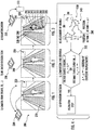
FIGS. 1-3 illustrates components of an escalator system according to an embodiment as well as system processes utilized to generate models of persons on an escalator according to an embodiment; -
FIG. 4 illustrates processes utilized to identify and respond to alert conditions when tracking the nodal models; and -
FIG. 5 illustrates an algorithm for performing the process illustrated inFIGS. 1-4 according to an embodiment. - Turning to
FIG. 1 , anescalator system 200 is disclosed comprising anescalator 210, asensor 220 operationally directed to engage theescalator 210, and acontroller 230 for controlling theescalator 210 andsensor 220.Sensor 220 can be, for example, in a form of video camera or infrared camera. One ormore sensors 220 can be used.Sensors 220 can be the same or a combination of different devices. It is to be appreciated that theescalator 210 can be another form of moving platform such as a moving walkway. - Turning to
FIG. 5 , thecontroller 230 is configured to render a plurality of determinations when performing a process S200 of escalator safety monitoring. At step S210 thecontroller 230 renders a first determination that theescalator 210 is in an operational state. - With reference to
FIG. 1-2 andFIG. 5 , at a second step S220 thecontroller 230 renders a second determination that first sensed data dynamically obtained from thesensor 220 is indicative of afirst passenger 240 on theescalator 210. This can be performed, for example, by comparing the sensed data with shapes stored in accessible memory to identify for example human body shapes. Different, already developed and/or future appropriate, computer vision methods for object recognitions can be utilized. - With reference to both
FIG. 3 andFIG. 5 , at a third step S230, thecontroller 230 renders a third determination to model the recognized shape of thefirst passenger 240, while thefirst passenger 240 is on theescalator 210, with afirst nodal model 250. As used herein a "nodal model" such asnodal model 250 is a population of all nodes in a recognized shape. The model of the shape can be defined, for example, in a form of a finite number of nodes and their positions in space, describing the shape with specified level of accuracy. An example shown inFIG. 3 illustrates such definition of themodel 250 through a finite number ofnodes - With reference to both
FIGS. 4 and5 , at a fourth step S240 thecontroller 230 renders a fourth determination to track displacement differentials as function of time of down-selected parameters of thefirst nodal model 250. In illustration shown inFIG. 3 , these parameters are, for example,nodes controller 230 renders a fifth determination to identify from the differentials as applied to a set of predetermined parameters 365, such as maximum allowed differentials for specific nodes grouped and individually, whether an alert condition has occurred with thefirst passenger 240. Similarly, some predetermined parameters can be applied for assessment of minimal allowed differentials for specific nodes grouped and individually. More complex predetermined mathematical conditions to correlate the alert conditions with the differentials can be applied in other embodiments as well. At a sixth step S260, when thecontroller 230 identifies an alert condition, thecontroller 230 renders a sixth determination to stop theescalator 210 or apply other specified service actions, such, for example, speed reduction, signal to a service management, etc. At a seventh step S270 thecontroller 230 transmits first instructions to theescalator 210 to effect the sixth determination. - Turning back to
FIG. 3 , thenodal model 250 may consist of one or more nodes representing one or more body joints for thefirst passenger 240 including, for example, one or more of: (i)head 280, (ii) one or bothshoulder joints 290, (iii) one or bothelbow joints 300, (iv) one or bothhip joints 310, (v) one or bothknee joints 320, (vi)pelvis 330, (vii) one or bothankle joints 335, (viii) one or bothhands 340, (ix) one or bothfeet 350, and (x) back orsternum 360, and (xi)neck 270. Other nodal definitions of human body can be equally used in different embodiments, for example, a center of gravity or mass for a body, a midpoint between eyes, etc., i.e., in general, any other locations of the body. - According to an embodiment the displacement differentials measured as relative nodal displacements per specified interval of time. These displacements include one or more of vertical displacements DV and/or horizontal displacements DH or geometrical metrics of motion in three-dimensional space, defined, for example, through length and/or angles. In addition, differential displacements may be calculated as a non-linear function of individual displacement differential components and/or their combinations. It is to be appreciated that displacements can be described in different forms, for example, length and angle, in polar or spherical coordinate systems, etc. Displacements can also be measured in different direction (e.g., parallel to the escalator, i.e., under certain angles).
- Displacement differentials defined as relative nodal displacements per specified interval of time are similar to physical meaning of a velocity, averaged per the same interval of time. More complex definitions of displacement differentials, for example, similar to physical meaning of acceleration, can be used in other embodiments as well. In these cases, measurements of nodal positions are needed per several, more than two, moments of time. These measurements can be then used in follow-up quantification of average acceleration according to well-established numerical methods for calculation of second derivatives.
- According to an embodiment the displacement differentials may be measured by the
controller 230 at a predetermined time interval to determine one or more displacement rates or combination of rates. According to an embodiment thecontroller 230 may determine that an alert condition exists when one or more displacement differentials are outside a predetermined range. According to an embodiment thecontroller 230 may determine an alert condition exists when one or more vertical displacement differentials and one or more respective vertical differential rates are above a first threshold. This may represent a falling passenger. It is to be appreciated that different body joints may have different thresholds that define an alert. For example rapid hand motion over a long span may not represent failing, while the same motion for a head may represent falling. According to an embodiment thecontroller 230 may determine an alert condition exists when one or more horizontal displacement differentials and a respective one or more horizontal differential rates are below a second threshold. This may represent apassenger 240 that is unable to depart theescalator 210. For example, thepassenger 240 may have clothing caught in an escalator tread. Although the above-mentioned examples are based on consideration of vertical or horizontal displacements, different definitions of the differentials per specified time interval can also be used in other embodiments, for example, in any orientation or in form of any angular movements or any of their combinations. - According to an embodiment the
sensor 220 may be at least one video camera, and/or at least one infrared (IR) camera or their combinations. According to an embodiment the system includes a building management system (BMS) 370. Thecontroller 230 may communicate an occurrence of an alert condition to theBMS 370. - The above disclosure provides one or more sensors including but not limited to video or IR camera(s) and one or more controllers to provide object recognition for 1) monitoring of escalator area(s) 2) obtaining sensed data representative of individual people on the escalator; 3) transforming the data into simplified forms comprising a finite number of selected metrics (for example, nodal positions of a head, elbows, knees, and connecting elements representing limbs.); 4) an assessment of the position change of nodes and elements as functions of time in a predetermined interval (delta t); 5) a quantifying of positional changes with previously defined alert criteria; and 6) halting of the escalator upon detection of an alert condition. Examples of such alert criteria may be, among other things, a relative change of vertical position of a node that is greater than a first threshold, where each node has a unique allowable threshold (head, knees, etc.) that indicate falling, or a change that is below a second threshold along a horizontal position of human foot (potentially indicating a person stuck between escalator steps). Upon halting the escalator, a corresponding signal (or actual image, video) may be sent to a dispatcher, for example, for further processing (for example, calling for help, etc.).
- The disclosed embodiments may provide benefits of both time (relatively immediate response) and cost (the process is relatively self-governing). The proposed system may not require change of existing escalator designs and may be relatively easily incorporated to existing systems.
- The above disclosed system comprises a conveyer system that moves passengers between floors and/or along a single floor. Such conveyer systems are identified herein as escalators, however other application to other forms of people movers is considered within the scope of the disclosure.
- A building management system (BMS), reference above, may be otherwise known as a building automation system (BAS). The BMS is a computer-based control system installed in buildings that may have a need for controlling and monitoring mechanical and electrical equipment such as ventilation, lighting, power systems, fire systems, security systems, fire alarm systems and elevator systems. In addition to controlling an internal environment in a building, BMS systems may provide for access control (access doors) for implementing building security protocols, or to control other security systems such as closed-circuit television (CCTV) and motion detectors. A BMS may be responsible for controlling equipment that accounts for a majority of energy usage in a building.
- As used herein, the controller, sensor, and other controllable devices may be considered "smart devices" and contain one or more processors capable of communication using with other such devices by applying wired and/or wireless telecommunication protocols. Protocols applied by smart devices may include local area network (LAN) protocols and/or a private area network (PAN) protocols. LAN protocols may apply Wi-Fi technology, which is a technology based on the Section 802.11 standards from the Institute of Electrical and Electronics Engineers, or IEEE. PAN protocols include, for example, Bluetooth Low Energy (BTLE), which is a wireless technology standard designed and marketed by the Bluetooth Special Interest Group (SIG) for exchanging data over short distances using short-wavelength radio waves. PAN protocols may also include Zigbee, a technology based on Section 802.15.4 protocols from the Institute of Electrical and Electronics Engineers (IEEE). More specifically, Zigbee represents a suite of high-level communication protocols used to create personal area networks with small, low-power digital radios for low-power low-bandwidth needs, and is best suited for small scale projects using wireless connections. Wireless protocols may further include short range communication (SRC) protocols, which may be utilized with radio-frequency identification (RFID) technology. RFID may be used for communicating with an integrated chip (IC) on an RFID smartcard. Wireless protocols may further include long range, low powered wide area network (LoRa and LPWAN) protocols that enable low data rate communications to be made over long distances by sensors and actuators for machine-to-machine (M2M) and Internet of Things (IoT) applications.
- As described above, embodiments can be in the form of processor-implemented processes and devices for practicing those processes, such as a processor. Embodiments can also be in the form of computer program code containing instructions embodied in tangible media, such as network cloud storage, SD cards, flash drives, floppy diskettes, CD ROMs, hard drives, or any other computer-readable storage medium, wherein, when the computer program code is loaded into and executed by a computer, the computer becomes a device for practicing the embodiments. Embodiments can also be in the form of computer program code, for example, whether stored in a storage medium, loaded into and/or executed by a computer, or transmitted over some transmission medium, loaded into and/or executed by a computer, or transmitted over some transmission medium, such as over electrical wiring or cabling, through fiber optics, or via electromagnetic radiation, wherein, when the computer program code is loaded into an executed by a computer, the computer becomes an device for practicing the embodiments. When implemented on a general-purpose microprocessor, the computer program code segments configure the microprocessor to create specific logic circuits.
- The terminology used herein is for the purpose of describing particular embodiments only and is not intended to be limiting of the present disclosure. As used herein, the singular forms "a", "an" and "the" are intended to include the plural forms as well, unless the context clearly indicates otherwise. It will be further understood that the terms "comprises" and/or "comprising," when used in this specification, specify the presence of stated features, integers, steps, operations, elements, and/or components, but do not preclude the presence or addition of one or more other features, integers, steps, operations, element components, and/or groups thereof.
- Those of skill in the art will appreciate that various example embodiments are shown and described herein, each having certain features in the particular embodiments, but the present disclosure is not thus limited. Rather, the present disclosure can be modified to incorporate any number of variations, alterations, substitutions, combinations, sub-combinations, or equivalent arrangements not heretofore described, but which are commensurate with the scope of the present disclosure. Additionally, while various embodiments of the present disclosure have been described, it is to be understood that aspects of the present disclosure may include only some of the described embodiments. Accordingly, the present disclosure is not to be seen as limited by the foregoing description, but is only limited by the scope of the appended claims.
Claims (15)
- A system comprising:a conveyer (210),a sensor (220) operationally directed to engage the conveyer (210),a controller (230) for controlling the conveyer (210) and the sensor (220),wherein the controller (230) is configured to render a plurality of determinations including:a first determination that the conveyer (210) is in an operational state,a second determination that first sensed data dynamically obtained from the sensor (220) is indicative of a first passenger (240) on the conveyer (210),a third determination to model shape of the first passenger (240), while the first passenger (240) is on the conveyer (210), with a first nodal model (250),a fourth determination to track displacement differentials for the first nodal model (250),a fifth determination to identify from the differentials an occurrence of an alert condition with the first passenger (240),at an occurrence of an alert condition, a sixth determination to stop the conveyer (210), andthe controller is configured to transmit first instructions to the conveyer (210) to effect the sixth determination.
- The system of claim 1 wherein the nodal model consists of one or more nodes representing the first passenger (240).
- The system of claim 2 wherein the one or more nodes represent points associated with physical features of the passenger including one or more of head, elbow, and knee.
- The system of claim 1, 2 or 3 wherein the displacement differentials include one or more of relative distance and/or angular displacements per specified interval of time or their combinations.
- The system of any preceding claim wherein the controller measures displacement differentials at a predetermined time interval to determine one or more displacement rates.
- The system of any preceding claim wherein the controller may determine an alert condition exists when one or more displacement differentials and/or one or more respective differential rates are outside a predetermined range.
- The system of any preceding claim wherein the controller may determine an alert condition exists when:one or more vertical displacement differentials and/or one or more respective vertical differential rates are above a first threshold, and/orone or more horizontal displacement differentials and/or one or more respective horizontal differential rates are below a second threshold, and/orone or more total displacement differentials and/or one or more respective total differential rates are below a third threshold, and/orone or more angular differentials and/or one or more respective angular differentials are below a fourth threshold.
- The system of any preceding claim wherein the sensor (220) is at least one video camera and/or, at least, one infrared camera or their combination.
- The system of any preceding claim wherein the conveyer system is an escalator or moving walkway.
- The system of any preceding claim comprising a building management system (BMS) (370) and the controller (230) communicates an occurrence of an alert condition to the BMS (370).
- A method of conveying a passenger with a system, the system including: a conveyer (210), a sensor (220) operationally directed to engage the conveyer (210), and a controller (230) for controlling the conveyer (210) and the sensor (220),
wherein the method comprises the controller (230):rendering a plurality of determinations including:a first determination that the conveyer (210) is in an operational state,a second determination that first sensed data dynamically obtained from the sensor (220) is indicative of a first passenger (240) on the conveyer (210),a third determination to model shape of the first passenger (240), while the first passenger (240) is on the conveyer (210), with a first nodal model (250),a fourth determination to track displacement differentials for the first nodal model (250),a fifth determination to identify from the differentials an occurrence of an alert condition with the first passenger (240),at an occurrence of an alert condition, a sixth determination to stop the conveyer (210), andtransmitting first instructions to the conveyer (210) to effect the sixth determination. - The method of claim 11 wherein the nodal model consists of one or more nodes representing the first passenger (240).
- The method of claim 12 wherein the one or more nodes represent points associated with physical features of the passenger including one or more of head, elbow, and knee.
- The method of claim 11, 12 or 13 wherein the displacement differentials include one or more of relative distance and/or angular displacements per specified interval of time or their combinations.
- The method of any of claims 11 to 14 wherein the controller measures displacement differentials at a predetermined time interval to determine one or more displacement rates.
Applications Claiming Priority (1)
| Application Number | Priority Date | Filing Date | Title |
|---|---|---|---|
| US16/168,442 US10351392B1 (en) | 2018-10-23 | 2018-10-23 | Escalator and moving walkway system with safety sensor |
Publications (2)
| Publication Number | Publication Date |
|---|---|
| EP3647251A1 true EP3647251A1 (en) | 2020-05-06 |
| EP3647251B1 EP3647251B1 (en) | 2022-11-30 |
Family
ID=67220480
Family Applications (1)
| Application Number | Title | Priority Date | Filing Date |
|---|---|---|---|
| EP19204841.1A Active EP3647251B1 (en) | 2018-10-23 | 2019-10-23 | Escalator and moving walkway system with safety sensor |
Country Status (3)
| Country | Link |
|---|---|
| US (1) | US10351392B1 (en) |
| EP (1) | EP3647251B1 (en) |
| CN (1) | CN111086944B (en) |
Families Citing this family (6)
| Publication number | Priority date | Publication date | Assignee | Title |
|---|---|---|---|---|
| AU2018241771B2 (en) * | 2017-03-28 | 2021-05-13 | Inventio Ag | Sensor network for a passenger transport system |
| JP7062789B2 (en) * | 2018-10-29 | 2022-05-06 | 株式会社日立製作所 | Passenger conveyor display device, as well as passenger conveyor |
| US11192757B2 (en) * | 2020-05-06 | 2021-12-07 | Techdayafter, Inc. | Method and system for ensuring social distancing on an escalator or travellator |
| EP4164979B1 (en) * | 2020-06-16 | 2025-05-14 | KONE Corporation | People mover |
| JP7518004B2 (en) * | 2021-01-13 | 2024-07-17 | 株式会社日立製作所 | Passenger conveyor, program, and passenger guidance system |
| TWI817311B (en) * | 2022-01-07 | 2023-10-01 | 宏碁股份有限公司 | Escalator equipment alert method and escalator equipment alert system |
Citations (6)
| Publication number | Priority date | Publication date | Assignee | Title |
|---|---|---|---|---|
| JP2010064821A (en) * | 2008-09-09 | 2010-03-25 | Toshiba Elevator Co Ltd | Escalator monitoring system |
| JP2014028667A (en) * | 2012-07-31 | 2014-02-13 | West Japan Railway Co | Escalator monitoring system |
| CN106241584A (en) * | 2016-08-23 | 2016-12-21 | 西尼电梯(杭州)有限公司 | A kind of intelligent video monitoring system based on staircase safety and method |
| CN106778481A (en) * | 2016-11-15 | 2017-05-31 | 上海百芝龙网络科技有限公司 | A kind of body heath's monitoring method |
| WO2017140568A1 (en) * | 2016-02-15 | 2017-08-24 | Thyssenkrupp Elevator Innovation Center S.A. | Method for controlling a transport device, namely an escalator or a moving walkway |
| CN107194967A (en) * | 2017-06-09 | 2017-09-22 | 南昌大学 | Human fall detection method and device based on Kinect depth image |
Family Cites Families (28)
| Publication number | Priority date | Publication date | Assignee | Title |
|---|---|---|---|---|
| JPH06329383A (en) * | 1993-05-21 | 1994-11-29 | Toshiba Corp | Escalator also serving as wheelchair |
| AUPN605295A0 (en) | 1995-10-18 | 1995-11-09 | Loderway Pty. Limited | Systems for the conveyance of standing passengers |
| DE19754141C2 (en) * | 1997-12-04 | 2000-05-25 | O & K Rolltreppen Gmbh | Safety device for escalators and moving walks |
| US6267219B1 (en) * | 2000-08-11 | 2001-07-31 | Otis Elevator Company | Electronic safety system for escalators |
| JP4865237B2 (en) | 2005-02-15 | 2012-02-01 | 株式会社日立製作所 | Passenger conveyor |
| US20060001545A1 (en) | 2005-05-04 | 2006-01-05 | Mr. Brian Wolf | Non-Intrusive Fall Protection Device, System and Method |
| JP5089304B2 (en) | 2007-09-13 | 2012-12-05 | 三菱電機株式会社 | Escalator safety device |
| CN101607668B (en) | 2008-06-17 | 2012-06-27 | 上海阿艾依智控系统有限公司 | Embedded computer vision escalator pedestrian flow supervision and alarm device |
| JP4595010B2 (en) | 2008-09-17 | 2010-12-08 | 株式会社日立製作所 | escalator |
| DE102009034345B4 (en) * | 2009-07-23 | 2013-01-03 | Kone Corp. | Method and device for operating a passenger transport device |
| RU2533653C2 (en) * | 2009-12-18 | 2014-11-20 | Отис Элевэйтор Компани | Detection of people relative to passenger conveyor with capacitive sensor |
| CN102464256A (en) * | 2010-11-05 | 2012-05-23 | 苏州新达电扶梯部件有限公司 | Intelligent drive control system of escalator |
| FI122473B (en) * | 2010-12-14 | 2012-02-15 | Kone Corp | Interface, transport system and method |
| DE102012003178B4 (en) * | 2012-02-17 | 2018-03-22 | Kone Corp. | Device for monitoring the function of an escalator or moving walkway |
| KR101329526B1 (en) | 2013-01-31 | 2013-11-14 | 한상진 | Escalator of real-time safe driving system and its control method |
| WO2015121751A2 (en) | 2014-02-16 | 2015-08-20 | Ghadamossoltani Amir Hussein | Intelligent escalator emergency stop system (ie2s2) |
| JP5770326B1 (en) * | 2014-03-10 | 2015-08-26 | 東芝エレベータ株式会社 | Escalator steps |
| CN106660756A (en) * | 2014-05-06 | 2017-05-10 | 奥的斯电梯公司 | Object detector, and method for controlling a passenger conveyor system using the same |
| GB2526368B (en) * | 2014-05-23 | 2019-10-09 | Kerett Electronic Services Ltd | Moving walkway safety system |
| WO2016046052A1 (en) * | 2014-09-26 | 2016-03-31 | Inventio Ag | Elevator system |
| US9779420B2 (en) * | 2014-10-20 | 2017-10-03 | Bernada Limited | Systems and methods for observing the movements of passengers on conveying devices |
| US10696517B2 (en) * | 2014-11-26 | 2020-06-30 | Otis Elevator Company | Elevator security and control system based on passenger movement |
| EP3088346A1 (en) | 2015-04-27 | 2016-11-02 | Thyssenkrupp Elevator Innovation Center, S.A. | Safety device and method for preventing accidents in the combplate area of escalators or moving walkways |
| CN106127148B (en) | 2016-06-21 | 2019-03-12 | 日立电梯(广州)自动扶梯有限公司 | A method for detecting abnormal behavior of escalator passengers based on machine vision |
| CN107662869B (en) | 2016-07-29 | 2021-06-29 | 奥的斯电梯公司 | Big data analysis processing system and method for passenger conveyor |
| CN107662867B (en) * | 2016-07-29 | 2021-03-30 | 奥的斯电梯公司 | Step roller monitoring and maintenance operator monitoring for passenger conveyors |
| CN107662871B (en) * | 2016-07-29 | 2021-04-06 | 奥的斯电梯公司 | Moving handrail monitoring system for passenger transportation device, passenger transportation device and monitoring method thereof |
| CN106503632A (en) | 2016-10-10 | 2017-03-15 | 南京理工大学 | A kind of escalator intelligent and safe monitoring method based on video analysis |
-
2018
- 2018-10-23 US US16/168,442 patent/US10351392B1/en active Active
-
2019
- 2019-10-22 CN CN201911005602.5A patent/CN111086944B/en active Active
- 2019-10-23 EP EP19204841.1A patent/EP3647251B1/en active Active
Patent Citations (6)
| Publication number | Priority date | Publication date | Assignee | Title |
|---|---|---|---|---|
| JP2010064821A (en) * | 2008-09-09 | 2010-03-25 | Toshiba Elevator Co Ltd | Escalator monitoring system |
| JP2014028667A (en) * | 2012-07-31 | 2014-02-13 | West Japan Railway Co | Escalator monitoring system |
| WO2017140568A1 (en) * | 2016-02-15 | 2017-08-24 | Thyssenkrupp Elevator Innovation Center S.A. | Method for controlling a transport device, namely an escalator or a moving walkway |
| CN106241584A (en) * | 2016-08-23 | 2016-12-21 | 西尼电梯(杭州)有限公司 | A kind of intelligent video monitoring system based on staircase safety and method |
| CN106778481A (en) * | 2016-11-15 | 2017-05-31 | 上海百芝龙网络科技有限公司 | A kind of body heath's monitoring method |
| CN107194967A (en) * | 2017-06-09 | 2017-09-22 | 南昌大学 | Human fall detection method and device based on Kinect depth image |
Also Published As
| Publication number | Publication date |
|---|---|
| CN111086944A (en) | 2020-05-01 |
| EP3647251B1 (en) | 2022-11-30 |
| CN111086944B (en) | 2022-06-03 |
| US10351392B1 (en) | 2019-07-16 |
Similar Documents
| Publication | Publication Date | Title |
|---|---|---|
| EP3647251B1 (en) | Escalator and moving walkway system with safety sensor | |
| US10102730B2 (en) | Monitoring apparatus for monitoring a targets exposure to danger | |
| Petersen et al. | Establishing an image-based ground truth for validation of sensor data-based room occupancy detection | |
| US20160377698A1 (en) | System and a method for tracking mobile objects using cameras and tag devices | |
| KR101765235B1 (en) | FACILITY MAINTENANCE SYSTEM USING INTERNET OF THINGS (IoT) BASED SENSOR AND UNMANNED AIR VEHICLE (UAV), AND METHOD FOR THE SAME | |
| CN102007426A (en) | Position-monitoring device for persons | |
| CN112573315B (en) | Air pressure and acceleration sensor floor correction by elevator status information | |
| KR102374021B1 (en) | System and method for determining a patient's fall situation | |
| US11258987B2 (en) | Anti-collision and motion control systems and methods | |
| CN116664359A (en) | An intelligent fire early warning decision-making system and method based on multi-sensor fusion | |
| US20240140759A1 (en) | Systems and method for detecting a location of a person in a hoistway | |
| JP2021078022A (en) | Apparatus for identifying terminal based on correspondence level with target on communication state, program, and method | |
| JP2021090088A (en) | Device, program, and method for identifying terminal on the basis of correspondence between communication type and target type | |
| EP3882199A2 (en) | Specialized, personalized and enhanced elevator calling for robots & co-bots | |
| KR101982404B1 (en) | Monitoring method for patient based on beacon and system for the same | |
| GB2537780A (en) | Person detecting device and person detecting method | |
| KR101853700B1 (en) | Indoor localization system in disaster relief and localization method thereof | |
| US20140114493A1 (en) | Environment control system, method for performing the same and computer readable medium | |
| KR101753349B1 (en) | User position prediction method using physical coordinate of smart device linked object recognition sensor and emergency evacuation route guidance and information delivery systems using the same | |
| CN110379131B (en) | A fall risk prediction method, system and device | |
| Miyazaki et al. | Estimation of the number of humans and their movement paths in a room using binary infrared sensors | |
| Chen et al. | EasyGO: A rapid indoor navigation and evacuation system using smartphones through Internet of Things technologies | |
| KR101437436B1 (en) | Method for estimating movement pattern with multi sensor data and smartwear using the same | |
| CN103389712B (en) | real-time device management system | |
| WO2020059918A1 (en) | Electronic monitoring system and control method thereof |
Legal Events
| Date | Code | Title | Description |
|---|---|---|---|
| PUAI | Public reference made under article 153(3) epc to a published international application that has entered the european phase |
Free format text: ORIGINAL CODE: 0009012 |
|
| STAA | Information on the status of an ep patent application or granted ep patent |
Free format text: STATUS: THE APPLICATION HAS BEEN PUBLISHED |
|
| AK | Designated contracting states |
Kind code of ref document: A1 Designated state(s): AL AT BE BG CH CY CZ DE DK EE ES FI FR GB GR HR HU IE IS IT LI LT LU LV MC MK MT NL NO PL PT RO RS SE SI SK SM TR |
|
| AX | Request for extension of the european patent |
Extension state: BA ME |
|
| STAA | Information on the status of an ep patent application or granted ep patent |
Free format text: STATUS: REQUEST FOR EXAMINATION WAS MADE |
|
| 17P | Request for examination filed |
Effective date: 20201106 |
|
| RBV | Designated contracting states (corrected) |
Designated state(s): AL AT BE BG CH CY CZ DE DK EE ES FI FR GB GR HR HU IE IS IT LI LT LU LV MC MK MT NL NO PL PT RO RS SE SI SK SM TR |
|
| STAA | Information on the status of an ep patent application or granted ep patent |
Free format text: STATUS: EXAMINATION IS IN PROGRESS |
|
| 17Q | First examination report despatched |
Effective date: 20210325 |
|
| GRAP | Despatch of communication of intention to grant a patent |
Free format text: ORIGINAL CODE: EPIDOSNIGR1 |
|
| STAA | Information on the status of an ep patent application or granted ep patent |
Free format text: STATUS: GRANT OF PATENT IS INTENDED |
|
| INTG | Intention to grant announced |
Effective date: 20220624 |
|
| GRAS | Grant fee paid |
Free format text: ORIGINAL CODE: EPIDOSNIGR3 |
|
| GRAA | (expected) grant |
Free format text: ORIGINAL CODE: 0009210 |
|
| STAA | Information on the status of an ep patent application or granted ep patent |
Free format text: STATUS: THE PATENT HAS BEEN GRANTED |
|
| AK | Designated contracting states |
Kind code of ref document: B1 Designated state(s): AL AT BE BG CH CY CZ DE DK EE ES FI FR GB GR HR HU IE IS IT LI LT LU LV MC MK MT NL NO PL PT RO RS SE SI SK SM TR |
|
| REG | Reference to a national code |
Ref country code: CH Ref legal event code: EP Ref country code: GB Ref legal event code: FG4D |
|
| REG | Reference to a national code |
Ref country code: AT Ref legal event code: REF Ref document number: 1534559 Country of ref document: AT Kind code of ref document: T Effective date: 20221215 |
|
| REG | Reference to a national code |
Ref country code: IE Ref legal event code: FG4D |
|
| REG | Reference to a national code |
Ref country code: DE Ref legal event code: R096 Ref document number: 602019022484 Country of ref document: DE |
|
| REG | Reference to a national code |
Ref country code: LT Ref legal event code: MG9D |
|
| REG | Reference to a national code |
Ref country code: NL Ref legal event code: MP Effective date: 20221130 |
|
| PG25 | Lapsed in a contracting state [announced via postgrant information from national office to epo] |
Ref country code: SE Free format text: LAPSE BECAUSE OF FAILURE TO SUBMIT A TRANSLATION OF THE DESCRIPTION OR TO PAY THE FEE WITHIN THE PRESCRIBED TIME-LIMIT Effective date: 20221130 Ref country code: PT Free format text: LAPSE BECAUSE OF FAILURE TO SUBMIT A TRANSLATION OF THE DESCRIPTION OR TO PAY THE FEE WITHIN THE PRESCRIBED TIME-LIMIT Effective date: 20230331 Ref country code: NO Free format text: LAPSE BECAUSE OF FAILURE TO SUBMIT A TRANSLATION OF THE DESCRIPTION OR TO PAY THE FEE WITHIN THE PRESCRIBED TIME-LIMIT Effective date: 20230228 Ref country code: LT Free format text: LAPSE BECAUSE OF FAILURE TO SUBMIT A TRANSLATION OF THE DESCRIPTION OR TO PAY THE FEE WITHIN THE PRESCRIBED TIME-LIMIT Effective date: 20221130 Ref country code: FI Free format text: LAPSE BECAUSE OF FAILURE TO SUBMIT A TRANSLATION OF THE DESCRIPTION OR TO PAY THE FEE WITHIN THE PRESCRIBED TIME-LIMIT Effective date: 20221130 Ref country code: ES Free format text: LAPSE BECAUSE OF FAILURE TO SUBMIT A TRANSLATION OF THE DESCRIPTION OR TO PAY THE FEE WITHIN THE PRESCRIBED TIME-LIMIT Effective date: 20221130 |
|
| REG | Reference to a national code |
Ref country code: AT Ref legal event code: MK05 Ref document number: 1534559 Country of ref document: AT Kind code of ref document: T Effective date: 20221130 |
|
| PG25 | Lapsed in a contracting state [announced via postgrant information from national office to epo] |
Ref country code: RS Free format text: LAPSE BECAUSE OF FAILURE TO SUBMIT A TRANSLATION OF THE DESCRIPTION OR TO PAY THE FEE WITHIN THE PRESCRIBED TIME-LIMIT Effective date: 20221130 Ref country code: PL Free format text: LAPSE BECAUSE OF FAILURE TO SUBMIT A TRANSLATION OF THE DESCRIPTION OR TO PAY THE FEE WITHIN THE PRESCRIBED TIME-LIMIT Effective date: 20221130 Ref country code: LV Free format text: LAPSE BECAUSE OF FAILURE TO SUBMIT A TRANSLATION OF THE DESCRIPTION OR TO PAY THE FEE WITHIN THE PRESCRIBED TIME-LIMIT Effective date: 20221130 Ref country code: IS Free format text: LAPSE BECAUSE OF FAILURE TO SUBMIT A TRANSLATION OF THE DESCRIPTION OR TO PAY THE FEE WITHIN THE PRESCRIBED TIME-LIMIT Effective date: 20230330 Ref country code: HR Free format text: LAPSE BECAUSE OF FAILURE TO SUBMIT A TRANSLATION OF THE DESCRIPTION OR TO PAY THE FEE WITHIN THE PRESCRIBED TIME-LIMIT Effective date: 20221130 Ref country code: GR Free format text: LAPSE BECAUSE OF FAILURE TO SUBMIT A TRANSLATION OF THE DESCRIPTION OR TO PAY THE FEE WITHIN THE PRESCRIBED TIME-LIMIT Effective date: 20230301 |
|
| PG25 | Lapsed in a contracting state [announced via postgrant information from national office to epo] |
Ref country code: NL Free format text: LAPSE BECAUSE OF FAILURE TO SUBMIT A TRANSLATION OF THE DESCRIPTION OR TO PAY THE FEE WITHIN THE PRESCRIBED TIME-LIMIT Effective date: 20221130 |
|
| PG25 | Lapsed in a contracting state [announced via postgrant information from national office to epo] |
Ref country code: SM Free format text: LAPSE BECAUSE OF FAILURE TO SUBMIT A TRANSLATION OF THE DESCRIPTION OR TO PAY THE FEE WITHIN THE PRESCRIBED TIME-LIMIT Effective date: 20221130 Ref country code: RO Free format text: LAPSE BECAUSE OF FAILURE TO SUBMIT A TRANSLATION OF THE DESCRIPTION OR TO PAY THE FEE WITHIN THE PRESCRIBED TIME-LIMIT Effective date: 20221130 Ref country code: EE Free format text: LAPSE BECAUSE OF FAILURE TO SUBMIT A TRANSLATION OF THE DESCRIPTION OR TO PAY THE FEE WITHIN THE PRESCRIBED TIME-LIMIT Effective date: 20221130 Ref country code: DK Free format text: LAPSE BECAUSE OF FAILURE TO SUBMIT A TRANSLATION OF THE DESCRIPTION OR TO PAY THE FEE WITHIN THE PRESCRIBED TIME-LIMIT Effective date: 20221130 Ref country code: CZ Free format text: LAPSE BECAUSE OF FAILURE TO SUBMIT A TRANSLATION OF THE DESCRIPTION OR TO PAY THE FEE WITHIN THE PRESCRIBED TIME-LIMIT Effective date: 20221130 Ref country code: AT Free format text: LAPSE BECAUSE OF FAILURE TO SUBMIT A TRANSLATION OF THE DESCRIPTION OR TO PAY THE FEE WITHIN THE PRESCRIBED TIME-LIMIT Effective date: 20221130 |
|
| PG25 | Lapsed in a contracting state [announced via postgrant information from national office to epo] |
Ref country code: SK Free format text: LAPSE BECAUSE OF FAILURE TO SUBMIT A TRANSLATION OF THE DESCRIPTION OR TO PAY THE FEE WITHIN THE PRESCRIBED TIME-LIMIT Effective date: 20221130 Ref country code: AL Free format text: LAPSE BECAUSE OF FAILURE TO SUBMIT A TRANSLATION OF THE DESCRIPTION OR TO PAY THE FEE WITHIN THE PRESCRIBED TIME-LIMIT Effective date: 20221130 |
|
| REG | Reference to a national code |
Ref country code: DE Ref legal event code: R097 Ref document number: 602019022484 Country of ref document: DE |
|
| PLBE | No opposition filed within time limit |
Free format text: ORIGINAL CODE: 0009261 |
|
| STAA | Information on the status of an ep patent application or granted ep patent |
Free format text: STATUS: NO OPPOSITION FILED WITHIN TIME LIMIT |
|
| 26N | No opposition filed |
Effective date: 20230831 |
|
| PG25 | Lapsed in a contracting state [announced via postgrant information from national office to epo] |
Ref country code: SI Free format text: LAPSE BECAUSE OF FAILURE TO SUBMIT A TRANSLATION OF THE DESCRIPTION OR TO PAY THE FEE WITHIN THE PRESCRIBED TIME-LIMIT Effective date: 20221130 |
|
| PG25 | Lapsed in a contracting state [announced via postgrant information from national office to epo] |
Ref country code: IT Free format text: LAPSE BECAUSE OF FAILURE TO SUBMIT A TRANSLATION OF THE DESCRIPTION OR TO PAY THE FEE WITHIN THE PRESCRIBED TIME-LIMIT Effective date: 20221130 Ref country code: MC Free format text: LAPSE BECAUSE OF FAILURE TO SUBMIT A TRANSLATION OF THE DESCRIPTION OR TO PAY THE FEE WITHIN THE PRESCRIBED TIME-LIMIT Effective date: 20221130 |
|
| REG | Reference to a national code |
Ref country code: CH Ref legal event code: PL |
|
| REG | Reference to a national code |
Ref country code: BE Ref legal event code: MM Effective date: 20231031 |
|
| PG25 | Lapsed in a contracting state [announced via postgrant information from national office to epo] |
Ref country code: LU Free format text: LAPSE BECAUSE OF NON-PAYMENT OF DUE FEES Effective date: 20231023 |
|
| GBPC | Gb: european patent ceased through non-payment of renewal fee |
Effective date: 20231023 |
|
| PG25 | Lapsed in a contracting state [announced via postgrant information from national office to epo] |
Ref country code: LU Free format text: LAPSE BECAUSE OF NON-PAYMENT OF DUE FEES Effective date: 20231023 |
|
| PG25 | Lapsed in a contracting state [announced via postgrant information from national office to epo] |
Ref country code: GB Free format text: LAPSE BECAUSE OF NON-PAYMENT OF DUE FEES Effective date: 20231023 |
|
| PG25 | Lapsed in a contracting state [announced via postgrant information from national office to epo] |
Ref country code: CH Free format text: LAPSE BECAUSE OF NON-PAYMENT OF DUE FEES Effective date: 20231031 |
|
| PG25 | Lapsed in a contracting state [announced via postgrant information from national office to epo] |
Ref country code: GB Free format text: LAPSE BECAUSE OF NON-PAYMENT OF DUE FEES Effective date: 20231023 Ref country code: CH Free format text: LAPSE BECAUSE OF NON-PAYMENT OF DUE FEES Effective date: 20231031 |
|
| PG25 | Lapsed in a contracting state [announced via postgrant information from national office to epo] |
Ref country code: BE Free format text: LAPSE BECAUSE OF NON-PAYMENT OF DUE FEES Effective date: 20231031 |
|
| PG25 | Lapsed in a contracting state [announced via postgrant information from national office to epo] |
Ref country code: IE Free format text: LAPSE BECAUSE OF NON-PAYMENT OF DUE FEES Effective date: 20231023 |
|
| PG25 | Lapsed in a contracting state [announced via postgrant information from national office to epo] |
Ref country code: IE Free format text: LAPSE BECAUSE OF NON-PAYMENT OF DUE FEES Effective date: 20231023 |
|
| PG25 | Lapsed in a contracting state [announced via postgrant information from national office to epo] |
Ref country code: BG Free format text: LAPSE BECAUSE OF FAILURE TO SUBMIT A TRANSLATION OF THE DESCRIPTION OR TO PAY THE FEE WITHIN THE PRESCRIBED TIME-LIMIT Effective date: 20221130 |
|
| PG25 | Lapsed in a contracting state [announced via postgrant information from national office to epo] |
Ref country code: BG Free format text: LAPSE BECAUSE OF FAILURE TO SUBMIT A TRANSLATION OF THE DESCRIPTION OR TO PAY THE FEE WITHIN THE PRESCRIBED TIME-LIMIT Effective date: 20221130 |
|
| PG25 | Lapsed in a contracting state [announced via postgrant information from national office to epo] |
Ref country code: CY Free format text: LAPSE BECAUSE OF FAILURE TO SUBMIT A TRANSLATION OF THE DESCRIPTION OR TO PAY THE FEE WITHIN THE PRESCRIBED TIME-LIMIT; INVALID AB INITIO Effective date: 20191023 |
|
| PG25 | Lapsed in a contracting state [announced via postgrant information from national office to epo] |
Ref country code: HU Free format text: LAPSE BECAUSE OF FAILURE TO SUBMIT A TRANSLATION OF THE DESCRIPTION OR TO PAY THE FEE WITHIN THE PRESCRIBED TIME-LIMIT; INVALID AB INITIO Effective date: 20191023 |
|
| PGFP | Annual fee paid to national office [announced via postgrant information from national office to epo] |
Ref country code: FR Payment date: 20250925 Year of fee payment: 7 |
|
| PG25 | Lapsed in a contracting state [announced via postgrant information from national office to epo] |
Ref country code: TR Free format text: LAPSE BECAUSE OF FAILURE TO SUBMIT A TRANSLATION OF THE DESCRIPTION OR TO PAY THE FEE WITHIN THE PRESCRIBED TIME-LIMIT Effective date: 20221130 |
|
| PGFP | Annual fee paid to national office [announced via postgrant information from national office to epo] |
Ref country code: DE Payment date: 20250923 Year of fee payment: 7 |