EP3647201A1 - Anti-icing system for an aircraft nacelle - Google Patents
Anti-icing system for an aircraft nacelle Download PDFInfo
- Publication number
- EP3647201A1 EP3647201A1 EP19207274.2A EP19207274A EP3647201A1 EP 3647201 A1 EP3647201 A1 EP 3647201A1 EP 19207274 A EP19207274 A EP 19207274A EP 3647201 A1 EP3647201 A1 EP 3647201A1
- Authority
- EP
- European Patent Office
- Prior art keywords
- bulkhead
- duct
- outer duct
- inner duct
- link
- Prior art date
- Legal status (The legal status is an assumption and is not a legal conclusion. Google has not performed a legal analysis and makes no representation as to the accuracy of the status listed.)
- Granted
Links
Images


Classifications
-
- B—PERFORMING OPERATIONS; TRANSPORTING
- B64—AIRCRAFT; AVIATION; COSMONAUTICS
- B64D—EQUIPMENT FOR FITTING IN OR TO AIRCRAFT; FLIGHT SUITS; PARACHUTES; ARRANGEMENT OR MOUNTING OF POWER PLANTS OR PROPULSION TRANSMISSIONS IN AIRCRAFT
- B64D15/00—De-icing or preventing icing on exterior surfaces of aircraft
- B64D15/02—De-icing or preventing icing on exterior surfaces of aircraft by ducted hot gas or liquid
- B64D15/04—Hot gas application
-
- F—MECHANICAL ENGINEERING; LIGHTING; HEATING; WEAPONS; BLASTING
- F02—COMBUSTION ENGINES; HOT-GAS OR COMBUSTION-PRODUCT ENGINE PLANTS
- F02C—GAS-TURBINE PLANTS; AIR INTAKES FOR JET-PROPULSION PLANTS; CONTROLLING FUEL SUPPLY IN AIR-BREATHING JET-PROPULSION PLANTS
- F02C7/00—Features, components parts, details or accessories, not provided for in, or of interest apart form groups F02C1/00 - F02C6/00; Air intakes for jet-propulsion plants
- F02C7/04—Air intakes for gas-turbine plants or jet-propulsion plants
- F02C7/047—Heating to prevent icing
-
- B—PERFORMING OPERATIONS; TRANSPORTING
- B64—AIRCRAFT; AVIATION; COSMONAUTICS
- B64D—EQUIPMENT FOR FITTING IN OR TO AIRCRAFT; FLIGHT SUITS; PARACHUTES; ARRANGEMENT OR MOUNTING OF POWER PLANTS OR PROPULSION TRANSMISSIONS IN AIRCRAFT
- B64D33/00—Arrangement in aircraft of power plant parts or auxiliaries not otherwise provided for
- B64D33/02—Arrangement in aircraft of power plant parts or auxiliaries not otherwise provided for of combustion air intakes
-
- B—PERFORMING OPERATIONS; TRANSPORTING
- B64—AIRCRAFT; AVIATION; COSMONAUTICS
- B64D—EQUIPMENT FOR FITTING IN OR TO AIRCRAFT; FLIGHT SUITS; PARACHUTES; ARRANGEMENT OR MOUNTING OF POWER PLANTS OR PROPULSION TRANSMISSIONS IN AIRCRAFT
- B64D33/00—Arrangement in aircraft of power plant parts or auxiliaries not otherwise provided for
- B64D33/02—Arrangement in aircraft of power plant parts or auxiliaries not otherwise provided for of combustion air intakes
- B64D2033/0233—Arrangement in aircraft of power plant parts or auxiliaries not otherwise provided for of combustion air intakes comprising de-icing means
-
- F—MECHANICAL ENGINEERING; LIGHTING; HEATING; WEAPONS; BLASTING
- F05—INDEXING SCHEMES RELATING TO ENGINES OR PUMPS IN VARIOUS SUBCLASSES OF CLASSES F01-F04
- F05D—INDEXING SCHEME FOR ASPECTS RELATING TO NON-POSITIVE-DISPLACEMENT MACHINES OR ENGINES, GAS-TURBINES OR JET-PROPULSION PLANTS
- F05D2220/00—Application
- F05D2220/30—Application in turbines
- F05D2220/32—Application in turbines in gas turbines
- F05D2220/323—Application in turbines in gas turbines for aircraft propulsion, e.g. jet engines
-
- F—MECHANICAL ENGINEERING; LIGHTING; HEATING; WEAPONS; BLASTING
- F05—INDEXING SCHEMES RELATING TO ENGINES OR PUMPS IN VARIOUS SUBCLASSES OF CLASSES F01-F04
- F05D—INDEXING SCHEME FOR ASPECTS RELATING TO NON-POSITIVE-DISPLACEMENT MACHINES OR ENGINES, GAS-TURBINES OR JET-PROPULSION PLANTS
- F05D2260/00—Function
- F05D2260/60—Fluid transfer
Definitions
- This disclosure relates generally to aircraft gas turbine engine nacelles, and more particularly to nacelle anti-ice systems.
- Ice formation on aircraft surfaces is undesirable and can lead to potentially hazardous flying conditions.
- the formation of ice on aircraft surfaces may reduce the performance of the aircraft by increasing weight or affecting aerodynamic properties of the aircraft.
- ice formations on the aircraft's surfaces may be drawn through the aircraft's gas turbine engines.
- aircraft may include anti-icing systems to prevent ice formation on, or to remove ice from, aircraft surfaces.
- One method of implementing such anti-icing systems is to direct heated gases from the gas turbine engine (e.g., engine bleed air) to interior or exterior surfaces of the aircraft, thereby increasing the temperature of the targeted aircraft surface.
- Similar anti-icing systems may use a double duct system to transmit heated gases from the gas turbine engine to the targeted aircraft surface while minimizing the risk of damage to aircraft components (e.g., acoustic composite structure of the gas turbine engine) as a result of a burst duct.
- the anti-icing systems may require complicated seal arrangements (e.g., high-temperature sliding seals) to couple the outer duct to support structures within the gas turbine engine nacelle.
- seal arrangements e.g., high-temperature sliding seals
- Such seal arrangements are heavy and provide limited responsiveness to vibration and deflection.
- Inner and outer ducts may also experience different rates and extents of thermal expansion.
- the use of complicated seal arrangements may limit possible orientations of the inner and outer ducts with respect to support structures within the gas turbine engine nacelle.
- an anti-icing system for an aircraft nacelle includes an inner duct and an outer duct.
- the inner duct extends through a first bulkhead between a gas turbine engine and a plenum of the nacelle.
- the inner duct is configured to deliver heated gases from the gas turbine engine to the plenum.
- the outer duct includes a first end and a second end.
- the outer duct circumferentially encompasses at least a portion of the inner duct on a first side of the bulkhead. At least one of the first end and the second end of the outer duct is mounted to at least one of the respective first bulkhead and a second bulkhead by a bellows forming an annular seal between the respective bulkhead and the outer duct.
- the bellows may be configured to mount at least one of the first end and the second end of the outer duct to at least one of the respective first bulkhead and the second bulkhead so as to form a cant angle of the outer duct with respect to at least one of the respective first bulkhead and the second bulkhead.
- the cant angle of the outer duct with respect to at least one of the first bulkhead and the second bulkhead may be between zero and forty-five degrees.
- the second end of the outer duct may be mounted to the second bulkhead.
- the anti-icing system may further include at least one link configured to support the inner duct on a second side of the first bulkhead, opposite the first side.
- the at least one link may be configured to prevent contact between the inner duct and the outer duct.
- the bellows may be made of Inconel.
- the at least one link may couple the inner duct to a fixed structure.
- the at least one link may be mounted to at least one of the fixed structure and the inner duct by at least one spherical bushing.
- the at least one link may be configured to be variably adjusted in length.
- an anti-icing system for an aircraft nacelle includes an inner duct and an outer duct.
- the inner duct extends through a first bulkhead between a gas turbine engine and a plenum of the nacelle.
- the inner duct is configured to deliver heated gases from the gas turbine engine to the plenum.
- the outer duct includes a first end and a second end.
- the outer duct circumferentially encompasses at least a portion of the inner duct on a first side of the bulkhead.
- the inner duct is supported by at least one link on a second side of the first bulkhead, opposite the first side.
- At least one of the first end and the second end of the outer duct may be mounted to at least one of the respective first bulkhead and the second bulkhead by a bellows forming an annular seal between the respective bulkhead and the outer duct.
- the bellows may be configured to mount at least one of the first end and the second end of the outer duct to at least one of the respective first bulkhead and the second bulkhead so as to form a cant angle of the outer duct with respect to at least one of the respective first bulkhead and the second bulkhead.
- the at least one link may couple the inner duct to a fixed structure.
- the at least one link may be mounted to at least one of the fixed structure and the inner duct by at least one spherical bushing.
- the at least one link may be configured to be variably adjusted in length.
- an anti-icing system for an aircraft nacelle includes an inner duct and an outer duct.
- the inner duct extends through a first bulkhead between a gas turbine engine and a plenum of the nacelle.
- the inner duct is configured to deliver heated gases from the gas turbine engine to the plenum.
- the outer duct includes a first end and a second end.
- the outer duct circumferentially encompasses at least a portion of the inner duct on a first side of the first bulkhead. At least one of the first end and the second end of the outer duct is mounted to at least one of the respective first bulkhead and a second bulkhead by a bellows forming an annular seal between the respective bulkhead and the outer duct.
- the inner duct is supported by at least one link on a second side of the first bulkhead, opposite the first side.
- the bellows may be configured to mount at least one of the first end and the second end of the outer duct to at least one of the respective first bulkhead and the second bulkhead so as to form a cant angle of the outer duct with respect to at least one of the respective first bulkhead and the second bulkhead.
- the cant angle of the outer duct with respect to at least one of the first bulkhead and the second bulkhead may be between zero and forty-five degrees.
- the at least one link may be configured to be variably adjusted in length.
- connections are set forth between elements in the following description and in the drawings. It is noted that these connections are general and, unless specified otherwise, may be direct or indirect and that this specification is not intended to be limiting in this respect.
- a coupling between two or more entities may refer to a direct connection or an indirect connection.
- An indirect connection may incorporate one or more intervening entities.
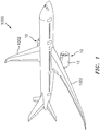
- an aircraft 1000 includes a gas turbine engine 10 mounted to, for example, a wing 1002 of the aircraft 1000.
- the gas turbine engine 10 includes a nacelle 12 defining a housing of the gas turbine engine 10 about a longitudinal axis 14.
- the longitudinal axis 14 extends through the center of the gas turbine engine 10 between a forward end 16 and an aft end 18 of the gas turbine engine 10.
- the gas turbine engine 10 generally includes a fan section 20, a compressor section 22, a combustor section 24, and a turbine section 26.
- the nacelle 12 includes an inlet surface 28 for directing air flow 30 toward the fan section 20 through an inlet section 32. Because the inlet surface 28 is located at the forward end 16, and therefore not heated directly by the gas turbine engine 10, the inlet surface 28 is prone to the accumulation of ice, especially along its forward lip surface 34 (i.e., the leading edge of the nacelle 12).
- the nacelle 12 includes a forward bulkhead 36 annularly arranged about the longitudinal axis 14.
- the inlet surface 28 and the forward bulkhead 36 define a forward plenum 38 housing portions of an anti-icing system 40.
- the anti-icing system 40 is configured to deliver heated gases 52 (e.g., bleed air from the compressor section 22 of the gas turbine engine 10) to the forward plenum 38 to prevent the formation of ice on the forward lip surface 34.
- the anti-icing system 40 includes a distribution ring 42 disposed within the forward plenum 38 and annularly arranged about the longitudinal axis 14.
- An inner duct 44 is configured to deliver heated gases 52 from the gas turbine engine 10 to the forward plenum 38 via the distribution ring 42 (e.g., through the forward bulkhead 36).
- the distribution ring 42 may be configured as a piccolo tube or any other suitable configuration for directing heated gases 52 to nacelle 12 surfaces.
- the inner duct 44 may extend between an engine build-up (EBU) outlet of the gas turbine engine 10 and the distribution ring 42.
- EBU engine build-up
- the distribution ring 42 distributes the hot gases within the forward plenum 38 thereby heating the forward lip surface 34 of the nacelle 12 to prevent formation of ice on the forward lip surface 34.
- the inner duct 44 may pass through one or more bulkheads along its length of travel between the gas turbine engine 10 and the distribution ring 42.
- the inner duct 44 may pass through an aft bulkhead 46 and the forward bulkhead 36. While the bulkheads 36, 46 are referred to herein as the forward bulkhead 36 and the aft bulkhead 46, it should be understood that bulkheads, such as bulkheads 36, 46, can have any orientation with respect to one another.
- the anti-icing system 40 includes an outer duct 48 circumferentially encompassing at least a portion of the inner duct 44.
- the outer duct 48 may encompass the length of the inner duct 44 between the forward bulkhead 36 and the aft bulkhead 46.
- This configuration allows the outer duct 48 to contain heated gases 52 from the gas turbine engine 10 as a result of a burst inner duct 44.
- the configuration further allows the inner duct 44 to continue directing heated gases 52 to the forward plenum 38 notwithstanding a burst inner duct 44.
- the outer duct 48 may be substantially parallel to the inner duct 44 along the length of the inner duct 44 encompassed by the outer duct 48 (e.g., to form a void between the inner duct 44 and the outer duct 48 while preventing contact between the ducts 44, 48 due to, for example, vibration and thermal expansion and contraction).
- a first end 48E1 of the outer duct 48 is mounted to the aft bulkhead 46 on a first side 46S1 of the aft bulkhead 46 by a bellows 50.
- the bellows 50 forms an annular seal between the aft bulkhead 46 and the outer duct 48.
- the bellows 50 may be welded to one or both of the aft bulkhead 46 and the outer duct 48 about the circumference of the bellows 50.
- the bellows 50 may be configured to accommodate vibration, lateral deflection, and thermal expansion and contraction of the outer duct 48 and one or both of the bulkheads 36, 46.
- the bellows 50 may be Inconel, titanium, or any other material suitable for high-temperature and/or high-pressure applications.
- a second end 48E2 of the outer duct 48 is mounted to a second bulkhead, such as the forward bulkhead 36.
- the inner duct 44, the outer duct 48, and the bellows 50 may form an enclosed annular void between the forward bulkhead 36 and the aft bulkhead 46.
- the bellows 50 may mount the second end 48E2 of the outer duct 48 to the forward bulkhead 36.
- the bellows 50 may include more than one bellows 50 which mount the first end 48E1 and the second end 48E2 of the outer duct 48 to the aft bulkhead 46 and the forward bulkhead 36, respectively.
- the bellows 50 may be configured to provide angularity between the ducts 44, 48 and one or more of the forward bulkhead 36 and the aft bulkhead 46 (e.g., to orient the inner duct 48 within the inlet surface 28 of the nacelle 12 as the inlet surface 28 narrows, radially, proximate the forward lip surface 34.
- the outer duct 48, and correspondingly the inner duct 44 may be described as "canted" (i.e., oriented at a non-perpendicular cant angle a) relative to the orientation of the aft bulkhead 46 (e.g., radial or non-radial with respect to longitudinal axis 14).
- the cant angle ⁇ of the outer duct 48 with respect to the aft bulkhead 46 may be between 0 and 20 degrees. However, in some embodiments, the cant angle ⁇ of the outer duct 48 with respect to the aft bulkhead 46 may be between 0 and 45 degrees.
- the anti-icing system 40 includes at least one link 54 configured to support the inner duct 44.
- the at least one link 54 couples the inner duct 44 to a fixed structure 58 of the gas turbine engine 10 (e.g., the nacelle 12 or an engine attach ring).
- the at least one link 54 may be mounted between the inner duct 44 and the fixed structure 58 at mounts 56 on a second side 46S2 of the aft bulkhead 46 (e.g., aft of the aft bulkhead 46).
- the mount 56 between the at least one link 54 and the fixed structure 58 may be oriented in any suitable direction (e.g., axially, radially, etc.).
- the mounts 56 may be configured to permit relative motion between the inner duct 44 and the fixed structure 58.
- the at least one link 54 may be any number of links (e.g., 1, 2, 3, 4, or more) necessary for support of the inner duct 48. Additionally, the at least one link 54 may be used independently or in combination with the bellows 50.
- the at least one link 54 may support and/or allow movement of the inner duct 44 in one or more of a radial, lateral, or axial direction.
- the at least one link 54 may allow the inner duct 44 to share thermal growth with EBU ducting aft of the inner duct 44 (e.g., by allowing the inner duct 44 to move forward or aft (e.g., axially), for example, as the EBU ducting expands or contracts).
- the at least one link 54 may allow thermal growth of the inner duct 44 without restricting or binding.
- the at least one link 54 may also reduce movement of the inner duct 44 as a result of vibration or lateral forces acting on the inner duct 44.
- the at least one link 54 may prevent or reduce deflection of the bellows 50 as a result of lateral loads on the inner duct 44. Accordingly, the at least one link 54 may prevent the inner duct 44 from contacting other components, such as the outer duct 48, thereby preventing or minimizing wear of the inner duct 44.
- one or more of the mounts 56 of the at least one link 54 may include spherical bushings.
- the at least one link 54 may have a fixed length L. In other embodiments, the at least one link 54 may be configured to be variably adjusted in length L (i.e., between the inner duct 44 and the fixed structure 58). For example, the length L of the at least one link 54 may be adjusted to minimize or eliminate preloading stress on the inner duct 44. In some embodiments, one or more of the at least one link 54 may have a different length L than another of the at least one link 54.
Landscapes
- Engineering & Computer Science (AREA)
- Chemical & Material Sciences (AREA)
- Combustion & Propulsion (AREA)
- Aviation & Aerospace Engineering (AREA)
- Mechanical Engineering (AREA)
- General Engineering & Computer Science (AREA)
- Sealing Devices (AREA)
Abstract
Description
- This disclosure relates generally to aircraft gas turbine engine nacelles, and more particularly to nacelle anti-ice systems.
- During aircraft operations, atmospheric conditions may lead to the formation of ice on the surfaces of the aircraft. Ice formation on aircraft surfaces, such as on the inlet of a gas turbine engine nacelle, is undesirable and can lead to potentially hazardous flying conditions. For example, the formation of ice on aircraft surfaces may reduce the performance of the aircraft by increasing weight or affecting aerodynamic properties of the aircraft. Further, ice formations on the aircraft's surfaces may be drawn through the aircraft's gas turbine engines.
- To address the above concerns, aircraft may include anti-icing systems to prevent ice formation on, or to remove ice from, aircraft surfaces. One method of implementing such anti-icing systems is to direct heated gases from the gas turbine engine (e.g., engine bleed air) to interior or exterior surfaces of the aircraft, thereby increasing the temperature of the targeted aircraft surface. Similar anti-icing systems may use a double duct system to transmit heated gases from the gas turbine engine to the targeted aircraft surface while minimizing the risk of damage to aircraft components (e.g., acoustic composite structure of the gas turbine engine) as a result of a burst duct.
- However, use of double duct anti-icing systems can present a number of complications. The anti-icing systems may require complicated seal arrangements (e.g., high-temperature sliding seals) to couple the outer duct to support structures within the gas turbine engine nacelle. Such seal arrangements are heavy and provide limited responsiveness to vibration and deflection. Inner and outer ducts may also experience different rates and extents of thermal expansion. Additionally, the use of complicated seal arrangements may limit possible orientations of the inner and outer ducts with respect to support structures within the gas turbine engine nacelle.
- According to an aspect of the present disclosure, an anti-icing system for an aircraft nacelle includes an inner duct and an outer duct. The inner duct extends through a first bulkhead between a gas turbine engine and a plenum of the nacelle. The inner duct is configured to deliver heated gases from the gas turbine engine to the plenum. The outer duct includes a first end and a second end. The outer duct circumferentially encompasses at least a portion of the inner duct on a first side of the bulkhead. At least one of the first end and the second end of the outer duct is mounted to at least one of the respective first bulkhead and a second bulkhead by a bellows forming an annular seal between the respective bulkhead and the outer duct.
- The bellows may be configured to mount at least one of the first end and the second end of the outer duct to at least one of the respective first bulkhead and the second bulkhead so as to form a cant angle of the outer duct with respect to at least one of the respective first bulkhead and the second bulkhead.
- The cant angle of the outer duct with respect to at least one of the first bulkhead and the second bulkhead may be between zero and forty-five degrees.
- The second end of the outer duct may be mounted to the second bulkhead.
- The anti-icing system may further include at least one link configured to support the inner duct on a second side of the first bulkhead, opposite the first side.
- The at least one link may be configured to prevent contact between the inner duct and the outer duct.
- The bellows may be made of Inconel.
- The at least one link may couple the inner duct to a fixed structure.
- The at least one link may be mounted to at least one of the fixed structure and the inner duct by at least one spherical bushing.
- The at least one link may be configured to be variably adjusted in length.
- According to another aspect of the present disclosure, an anti-icing system for an aircraft nacelle includes an inner duct and an outer duct. The inner duct extends through a first bulkhead between a gas turbine engine and a plenum of the nacelle. The inner duct is configured to deliver heated gases from the gas turbine engine to the plenum. The outer duct includes a first end and a second end. The outer duct circumferentially encompasses at least a portion of the inner duct on a first side of the bulkhead. The inner duct is supported by at least one link on a second side of the first bulkhead, opposite the first side.
- At least one of the first end and the second end of the outer duct may be mounted to at least one of the respective first bulkhead and the second bulkhead by a bellows forming an annular seal between the respective bulkhead and the outer duct.
- The bellows may be configured to mount at least one of the first end and the second end of the outer duct to at least one of the respective first bulkhead and the second bulkhead so as to form a cant angle of the outer duct with respect to at least one of the respective first bulkhead and the second bulkhead.
- The at least one link may couple the inner duct to a fixed structure.
- The at least one link may be mounted to at least one of the fixed structure and the inner duct by at least one spherical bushing.
- The at least one link may be configured to be variably adjusted in length.
- According to another aspect of the present disclosure, an anti-icing system for an aircraft nacelle includes an inner duct and an outer duct. The inner duct extends through a first bulkhead between a gas turbine engine and a plenum of the nacelle. The inner duct is configured to deliver heated gases from the gas turbine engine to the plenum. The outer duct includes a first end and a second end. The outer duct circumferentially encompasses at least a portion of the inner duct on a first side of the first bulkhead. At least one of the first end and the second end of the outer duct is mounted to at least one of the respective first bulkhead and a second bulkhead by a bellows forming an annular seal between the respective bulkhead and the outer duct. The inner duct is supported by at least one link on a second side of the first bulkhead, opposite the first side.
- The bellows may be configured to mount at least one of the first end and the second end of the outer duct to at least one of the respective first bulkhead and the second bulkhead so as to form a cant angle of the outer duct with respect to at least one of the respective first bulkhead and the second bulkhead.
- The cant angle of the outer duct with respect to at least one of the first bulkhead and the second bulkhead may be between zero and forty-five degrees.
- The at least one link may be configured to be variably adjusted in length.
- The present disclosure, and all its aspects, embodiments and advantages associated therewith will become more readily apparent in view of the detailed description provided below, including the accompanying drawings.
-
-
FIG. 1 is a perspective view of an aircraft including a gas turbine engine. -
FIG. 2 is a side, cross-sectional view of a gas turbine engine. -
FIG. 3 is a side, cross-sectional view of an exemplary anti-icing system of the gas turbine engine ofFIG. 2 . -
FIG. 3A is a side-cross sectional view of another exemplary anti-icing system of the gas turbine engine ofFIG. 2 . -
FIG. 4 is an aft-end view of the anti-icing system ofFIG. 3 . - It is noted that various connections are set forth between elements in the following description and in the drawings. It is noted that these connections are general and, unless specified otherwise, may be direct or indirect and that this specification is not intended to be limiting in this respect. A coupling between two or more entities may refer to a direct connection or an indirect connection. An indirect connection may incorporate one or more intervening entities.
- Referring to
FIGS. 1 and2 , anaircraft 1000 includes agas turbine engine 10 mounted to, for example, awing 1002 of theaircraft 1000. Thegas turbine engine 10 includes anacelle 12 defining a housing of thegas turbine engine 10 about alongitudinal axis 14. Thelongitudinal axis 14 extends through the center of thegas turbine engine 10 between aforward end 16 and anaft end 18 of thegas turbine engine 10. Thegas turbine engine 10 generally includes afan section 20, acompressor section 22, acombustor section 24, and aturbine section 26. Thenacelle 12 includes aninlet surface 28 for directingair flow 30 toward thefan section 20 through aninlet section 32. Because theinlet surface 28 is located at theforward end 16, and therefore not heated directly by thegas turbine engine 10, theinlet surface 28 is prone to the accumulation of ice, especially along its forward lip surface 34 (i.e., the leading edge of the nacelle 12). - Referring to
FIGS. 2 and3 , thenacelle 12 includes aforward bulkhead 36 annularly arranged about thelongitudinal axis 14. Theinlet surface 28 and theforward bulkhead 36 define aforward plenum 38 housing portions of an anti-icing system 40. The anti-icing system 40 is configured to deliver heated gases 52 (e.g., bleed air from thecompressor section 22 of the gas turbine engine 10) to theforward plenum 38 to prevent the formation of ice on theforward lip surface 34. - The anti-icing system 40 includes a
distribution ring 42 disposed within theforward plenum 38 and annularly arranged about thelongitudinal axis 14. Aninner duct 44 is configured to deliverheated gases 52 from thegas turbine engine 10 to theforward plenum 38 via the distribution ring 42 (e.g., through the forward bulkhead 36). Thedistribution ring 42 may be configured as a piccolo tube or any other suitable configuration for directingheated gases 52 to nacelle 12 surfaces. For example, theinner duct 44 may extend between an engine build-up (EBU) outlet of thegas turbine engine 10 and thedistribution ring 42. Thedistribution ring 42, in turn, distributes the hot gases within theforward plenum 38 thereby heating theforward lip surface 34 of thenacelle 12 to prevent formation of ice on theforward lip surface 34. Theinner duct 44 may pass through one or more bulkheads along its length of travel between thegas turbine engine 10 and thedistribution ring 42. For example, theinner duct 44 may pass through anaft bulkhead 46 and theforward bulkhead 36. While thebulkheads forward bulkhead 36 and theaft bulkhead 46, it should be understood that bulkheads, such asbulkheads - The anti-icing system 40 includes an
outer duct 48 circumferentially encompassing at least a portion of theinner duct 44. For example, theouter duct 48 may encompass the length of theinner duct 44 between theforward bulkhead 36 and theaft bulkhead 46. This configuration allows theouter duct 48 to containheated gases 52 from thegas turbine engine 10 as a result of a burstinner duct 44. The configuration further allows theinner duct 44 to continue directingheated gases 52 to theforward plenum 38 notwithstanding a burstinner duct 44. Theouter duct 48 may be substantially parallel to theinner duct 44 along the length of theinner duct 44 encompassed by the outer duct 48 (e.g., to form a void between theinner duct 44 and theouter duct 48 while preventing contact between theducts - In some embodiments, a first end 48E1 of the
outer duct 48 is mounted to theaft bulkhead 46 on a first side 46S1 of theaft bulkhead 46 by abellows 50. The bellows 50 forms an annular seal between theaft bulkhead 46 and theouter duct 48. For example, thebellows 50 may be welded to one or both of theaft bulkhead 46 and theouter duct 48 about the circumference of thebellows 50. The bellows 50 may be configured to accommodate vibration, lateral deflection, and thermal expansion and contraction of theouter duct 48 and one or both of thebulkheads bellows 50 may be Inconel, titanium, or any other material suitable for high-temperature and/or high-pressure applications. - In some embodiments, a second end 48E2 of the
outer duct 48 is mounted to a second bulkhead, such as theforward bulkhead 36. In such a configuration, theinner duct 44, theouter duct 48, and thebellows 50 may form an enclosed annular void between theforward bulkhead 36 and theaft bulkhead 46. In some embodiments, thebellows 50 may mount the second end 48E2 of theouter duct 48 to theforward bulkhead 36. In some other embodiments, thebellows 50 may include more than one bellows 50 which mount the first end 48E1 and the second end 48E2 of theouter duct 48 to theaft bulkhead 46 and theforward bulkhead 36, respectively. - Referring to
FIG. 3A , in some embodiments, thebellows 50 may be configured to provide angularity between theducts forward bulkhead 36 and the aft bulkhead 46 (e.g., to orient theinner duct 48 within theinlet surface 28 of thenacelle 12 as theinlet surface 28 narrows, radially, proximate theforward lip surface 34. For example, theouter duct 48, and correspondingly theinner duct 44, may be described as "canted" (i.e., oriented at a non-perpendicular cant angle a) relative to the orientation of the aft bulkhead 46 (e.g., radial or non-radial with respect to longitudinal axis 14). The cant angle α of theouter duct 48 with respect to theaft bulkhead 46 may be between 0 and 20 degrees. However, in some embodiments, the cant angle α of theouter duct 48 with respect to theaft bulkhead 46 may be between 0 and 45 degrees. - Referring to
FIGS. 3 and4 , in some embodiments, the anti-icing system 40 includes at least onelink 54 configured to support theinner duct 44. The at least onelink 54 couples theinner duct 44 to a fixedstructure 58 of the gas turbine engine 10 (e.g., thenacelle 12 or an engine attach ring). For example, the at least onelink 54 may be mounted between theinner duct 44 and the fixedstructure 58 atmounts 56 on a second side 46S2 of the aft bulkhead 46 (e.g., aft of the aft bulkhead 46). Themount 56 between the at least onelink 54 and the fixedstructure 58 may be oriented in any suitable direction (e.g., axially, radially, etc.). Themounts 56 may be configured to permit relative motion between theinner duct 44 and the fixedstructure 58. The at least onelink 54 may be any number of links (e.g., 1, 2, 3, 4, or more) necessary for support of theinner duct 48. Additionally, the at least onelink 54 may be used independently or in combination with thebellows 50. - The at least one
link 54 may support and/or allow movement of theinner duct 44 in one or more of a radial, lateral, or axial direction. For example, the at least onelink 54 may allow theinner duct 44 to share thermal growth with EBU ducting aft of the inner duct 44 (e.g., by allowing theinner duct 44 to move forward or aft (e.g., axially), for example, as the EBU ducting expands or contracts). Additionally, the at least onelink 54 may allow thermal growth of theinner duct 44 without restricting or binding. The at least onelink 54 may also reduce movement of theinner duct 44 as a result of vibration or lateral forces acting on theinner duct 44. For example, in some embodiments, the at least onelink 54 may prevent or reduce deflection of thebellows 50 as a result of lateral loads on theinner duct 44. Accordingly, the at least onelink 54 may prevent theinner duct 44 from contacting other components, such as theouter duct 48, thereby preventing or minimizing wear of theinner duct 44. In some embodiments, one or more of themounts 56 of the at least onelink 54 may include spherical bushings. - In some embodiments, the at least one
link 54 may have a fixed length L. In other embodiments, the at least onelink 54 may be configured to be variably adjusted in length L (i.e., between theinner duct 44 and the fixed structure 58). For example, the length L of the at least onelink 54 may be adjusted to minimize or eliminate preloading stress on theinner duct 44. In some embodiments, one or more of the at least onelink 54 may have a different length L than another of the at least onelink 54. - While various aspects of the present disclosure have been disclosed, it will be apparent to those of ordinary skill in the art that many more embodiments and implementations are possible within the scope of the present disclosure. For example, the present disclosure as described herein includes several aspects and embodiments that include particular features. Although these particular features may be described individually, it is within the scope of the present disclosure that some or all of these features may be combined with any one of the aspects and remain within the scope of the present disclosure. Accordingly, the present disclosure is not to be restricted except in light of the attached claims and their equivalents.
Claims (15)
- An anti-icing system (40) for an aircraft nacelle (12) comprising:an inner duct (44) extending through a first bulkhead (46) between a gas turbine engine (10) and a plenum (38) of the nacelle (12), the inner duct (44) configured to deliver heated gases from the gas turbine engine (10) to the plenum (38); andan outer duct (48) comprising a first end (48E1) and a second end (48E2), the outer duct (48) circumferentially encompassing at least a portion of the inner duct (44) on a first side (46S1) of the first bulkhead (46);wherein at least one of the first end (48E1) and the second end (48E2) of the outer duct (48) is mounted to at least one of the respective first bulkhead (46) and a second bulkhead (36) by a bellows (50) forming an annular seal between the respective bulkhead (46, 36) and the outer duct (48).
- The system (40) of claim 1, wherein the bellows (50) is configured to mount at least one of the first end (48E1) and the second end (48E2) of the outer duct (48) to at least one of the respective first bulkhead (46) and the second bulkhead (36) so as to form a cant angle (α) of the outer duct (48) with respect to at least one of the respective first bulkhead (46) and the second bulkhead (36).
- The system (40) of claim 2, wherein the cant angle (α) of the outer duct (48) with respect to at least one of the first bulkhead (46) and the second bulkhead (36) is between zero and forty-five degrees.
- The system (40) of claim 1, 2 or 3, wherein the second end (48E2) of the outer duct (48) is mounted to the second bulkhead (36).
- The system (40) of any preceding claim, wherein the bellows (50) is made of Inconel.
- The system (40) of any preceding claim, further comprising at least one link (54) configured to support the inner duct (44) on a second side (46S2) of the first bulkhead (46), opposite the first side (46S1).
- The system (40) of claim 6, wherein the at least one link (54) is configured to prevent contact between the inner duct (44) and the outer duct (48).
- The system (40) of claim 6 or 7, wherein the at least one link (54) is configured to be variably adjusted in length (L).
- An anti-icing system (40) for an aircraft nacelle (12) comprising:an inner duct (44) extending through a first bulkhead (46) between a gas turbine engine (10) and a plenum (38) of the nacelle (12), the inner duct (44) configured to deliver heated gases from the gas turbine engine (10) to the plenum (38); andan outer duct (48) comprising a first end (48E1) and a second end (48E2), the outer duct (48) circumferentially encompassing at least a portion of the inner duct (44) on a first side (46S1) of the first bulkhead (46);wherein the inner duct (44) is supported by at least one link (54) on a second side (46S2) of the first bulkhead (46), opposite the first side (46S1).
- The system (40) of claim 9, wherein at least one of the first end (48E1) and the second end (48E2) of the outer duct (48) is mounted to at least one of the respective first bulkhead (46) and the second bulkhead (36) by a bellows (50) forming an annular seal between the respective bulkhead (46, 36) and the outer duct (48).
- The system (40) of claim 10, wherein the bellows (50) is configured to mount at least one of the first end (48E1) and the second end (48E2) of the outer duct (48) to at least one of the respective first bulkhead (46) and the second bulkhead (36) so as to form a cant angle (α) of the outer duct (48) with respect to at least one of the respective first bulkhead (46) and the second bulkhead (36).
- The system (40) of claim 11, wherein the cant angle (α) of the outer duct (48) with respect to at least one of the first bulkhead (46) and the second bulkhead (36) is between zero and forty-five degrees.
- The system (40) of any of claims 9 to 12, wherein the at least one link (54) is configured to be variably adjusted in length (L).
- The system (40) of any of claims 6 to 13, wherein the at least one link (54) couples the inner duct (44) to a fixed structure (58).
- The system (40) of claim 14, wherein the at least one link (54) is mounted to at least one of the fixed structure (58) and the inner duct (44) by at least one spherical bushing.
Applications Claiming Priority (1)
| Application Number | Priority Date | Filing Date | Title |
|---|---|---|---|
| US16/180,684 US11408341B2 (en) | 2018-11-05 | 2018-11-05 | Anti-icing system for an aircraft nacelle |
Publications (2)
| Publication Number | Publication Date |
|---|---|
| EP3647201A1 true EP3647201A1 (en) | 2020-05-06 |
| EP3647201B1 EP3647201B1 (en) | 2022-03-30 |
Family
ID=68470273
Family Applications (1)
| Application Number | Title | Priority Date | Filing Date |
|---|---|---|---|
| EP19207274.2A Active EP3647201B1 (en) | 2018-11-05 | 2019-11-05 | Anti-icing system for an aircraft nacelle |
Country Status (2)
| Country | Link |
|---|---|
| US (1) | US11408341B2 (en) |
| EP (1) | EP3647201B1 (en) |
Families Citing this family (2)
| Publication number | Priority date | Publication date | Assignee | Title |
|---|---|---|---|---|
| FR3099912B1 (en) * | 2019-08-18 | 2021-08-13 | Safran Nacelles | Air inlet of an aircraft turbomachine nacelle |
| US11085328B2 (en) * | 2019-09-09 | 2021-08-10 | Rohr, Inc. | Assembly for sealing an annular gap between an inner structure and an outer structure |
Citations (8)
| Publication number | Priority date | Publication date | Assignee | Title |
|---|---|---|---|---|
| US4674714A (en) * | 1984-10-08 | 1987-06-23 | Short Brothers Plc | Duct for hot air |
| EP1318283A1 (en) * | 2001-12-06 | 2003-06-11 | Hurel-Hispano | De-icing device for aircraft outer skin |
| US20090152401A1 (en) * | 2007-12-12 | 2009-06-18 | Spirit Aerosystems, Inc. | Nacelle inlet thermal anti-icing spray duct support system |
| US20090314899A1 (en) * | 2006-08-04 | 2009-12-24 | Airbus France, Societe Par Actions Simplifiee | Structural element of an aircraft |
| US8047470B2 (en) * | 2006-03-27 | 2011-11-01 | Airbus Operations Sas | System for deicing an air inlet cowl for a turbine engine |
| FR2961174A1 (en) * | 2010-06-10 | 2011-12-16 | Airbus Operations Sas | Fluid i.e. hot air, guiding device for use in aircraft, has inner pipe placed inside outer pipe, where rear end of inner pipe includes coupling unit that couples rear end of inner pipe with supply element |
| US8308110B2 (en) * | 2005-06-21 | 2012-11-13 | Airbus Operations Sas | System for defrosting the leading edge sheath of an air inlet hood for a turboengine |
| EP2846023A1 (en) * | 2013-08-21 | 2015-03-11 | The Boeing Company | Aircraft engine anti-icing (eai) barrier assembly, system and method |
Family Cites Families (14)
| Publication number | Priority date | Publication date | Assignee | Title |
|---|---|---|---|---|
| US3933327A (en) | 1974-08-30 | 1976-01-20 | Rohr Industries, Inc. | Aircraft anti-icing plenum |
| US5088277A (en) * | 1988-10-03 | 1992-02-18 | General Electric Company | Aircraft engine inlet cowl anti-icing system |
| US5011098A (en) | 1988-12-30 | 1991-04-30 | The Boeing Company | Thermal anti-icing system for aircraft |
| GB9120113D0 (en) * | 1991-09-20 | 1992-09-23 | Short Brothers Plc | Thermal antiicing of aircraft structures |
| US5370427A (en) * | 1994-01-10 | 1994-12-06 | General Electric Company | Expansion joint for fluid piping with rotation prevention member |
| US6354538B1 (en) | 1999-10-25 | 2002-03-12 | Rohr, Inc. | Passive control of hot air injection for swirling rotational type anti-icing system |
| US8382039B2 (en) | 2009-12-30 | 2013-02-26 | MRA Systems Inc. | Turbomachine nacelle and anti-icing system and method therefor |
| DE102011102458A1 (en) | 2011-05-24 | 2012-11-29 | Rolls-Royce Deutschland Ltd & Co Kg | Deicing device of an aircraft gas turbine engine |
| DE102012000890A1 (en) | 2012-01-18 | 2013-07-18 | Rolls-Royce Deutschland Ltd & Co Kg | Fastening element and deicing device of an aircraft gas turbine engine |
| WO2014137553A1 (en) * | 2013-03-06 | 2014-09-12 | United Technologies Coproration | Exhaust system having a flow path liner supported by structural duct segments |
| US20140263837A1 (en) | 2013-03-12 | 2014-09-18 | Spirit Aerosystems, Inc. | Nacelle inlet thermal anti-ice spray duct |
| US9950799B2 (en) | 2016-03-09 | 2018-04-24 | Honeywell International Inc. | Shielded anti-icing system and methods |
| US9849992B2 (en) | 2016-05-23 | 2017-12-26 | United Technologies Corporation | Inline pressure regulating valve assembly with inlet pressure bias |
| US10823061B2 (en) | 2016-07-15 | 2020-11-03 | General Electric Company | Engine air inlet having a double-panel heated wall |
-
2018
- 2018-11-05 US US16/180,684 patent/US11408341B2/en active Active
-
2019
- 2019-11-05 EP EP19207274.2A patent/EP3647201B1/en active Active
Patent Citations (8)
| Publication number | Priority date | Publication date | Assignee | Title |
|---|---|---|---|---|
| US4674714A (en) * | 1984-10-08 | 1987-06-23 | Short Brothers Plc | Duct for hot air |
| EP1318283A1 (en) * | 2001-12-06 | 2003-06-11 | Hurel-Hispano | De-icing device for aircraft outer skin |
| US8308110B2 (en) * | 2005-06-21 | 2012-11-13 | Airbus Operations Sas | System for defrosting the leading edge sheath of an air inlet hood for a turboengine |
| US8047470B2 (en) * | 2006-03-27 | 2011-11-01 | Airbus Operations Sas | System for deicing an air inlet cowl for a turbine engine |
| US20090314899A1 (en) * | 2006-08-04 | 2009-12-24 | Airbus France, Societe Par Actions Simplifiee | Structural element of an aircraft |
| US20090152401A1 (en) * | 2007-12-12 | 2009-06-18 | Spirit Aerosystems, Inc. | Nacelle inlet thermal anti-icing spray duct support system |
| FR2961174A1 (en) * | 2010-06-10 | 2011-12-16 | Airbus Operations Sas | Fluid i.e. hot air, guiding device for use in aircraft, has inner pipe placed inside outer pipe, where rear end of inner pipe includes coupling unit that couples rear end of inner pipe with supply element |
| EP2846023A1 (en) * | 2013-08-21 | 2015-03-11 | The Boeing Company | Aircraft engine anti-icing (eai) barrier assembly, system and method |
Also Published As
| Publication number | Publication date |
|---|---|
| US20200141317A1 (en) | 2020-05-07 |
| US11408341B2 (en) | 2022-08-09 |
| EP3647201B1 (en) | 2022-03-30 |
Similar Documents
| Publication | Publication Date | Title |
|---|---|---|
| EP0852669B1 (en) | Convertible ejector cooled nozzle | |
| US7581399B2 (en) | Damped coil pin for attachment hanger hinge | |
| US8132755B2 (en) | Engine exhaust system with directional nozzle | |
| EP3320184B1 (en) | Flexural interface for bellowed ball-joint assemblies for controlled rotational constraint | |
| US20090079186A1 (en) | Flexible fitting for rigid tubing assembly | |
| EP3173589B1 (en) | Turbine engine and exhaust system connection | |
| EP2497908B1 (en) | A conduit for bleed air in a gas turbine engine | |
| EP3354857B1 (en) | Flexible joints assembly with flexure rods | |
| EP3647201B1 (en) | Anti-icing system for an aircraft nacelle | |
| EP0623742A1 (en) | Nozzle seal assembly with removable baseplate | |
| EP3705403B1 (en) | Inlet anti-ice double walled duct with supply line seal | |
| EP3670347A1 (en) | Anti-ice double walled duct system | |
| US7331612B2 (en) | Low profile tension style flexible joint | |
| EP3354578B1 (en) | Flexible joints assembly with flexure rods | |
| US11492998B2 (en) | Flexible aft cowls for aircraft | |
| CN105408610A (en) | Combustion gas discharge nozzle for a rocket engine provided with a sealing device between a stationary part and a moving part of the nozzle | |
| GB2517028A (en) | Interface device between two turbomachine elements | |
| US20130084170A1 (en) | Gas turbine engine mounting arrangements | |
| US10871084B2 (en) | Mount assembly | |
| EP3480447B1 (en) | Exhaust assembly mounting configuration | |
| US20190226424A1 (en) | Aircraft nozzle | |
| US11549394B2 (en) | Turbine casing cooling device for a turbomachine | |
| CN114302848B (en) | Air intake pipe of aircraft turbine engine nacelle |
Legal Events
| Date | Code | Title | Description |
|---|---|---|---|
| PUAI | Public reference made under article 153(3) epc to a published international application that has entered the european phase |
Free format text: ORIGINAL CODE: 0009012 |
|
| STAA | Information on the status of an ep patent application or granted ep patent |
Free format text: STATUS: THE APPLICATION HAS BEEN PUBLISHED |
|
| AK | Designated contracting states |
Kind code of ref document: A1 Designated state(s): AL AT BE BG CH CY CZ DE DK EE ES FI FR GB GR HR HU IE IS IT LI LT LU LV MC MK MT NL NO PL PT RO RS SE SI SK SM TR |
|
| AX | Request for extension of the european patent |
Extension state: BA ME |
|
| STAA | Information on the status of an ep patent application or granted ep patent |
Free format text: STATUS: REQUEST FOR EXAMINATION WAS MADE |
|
| 17P | Request for examination filed |
Effective date: 20201105 |
|
| RBV | Designated contracting states (corrected) |
Designated state(s): AL AT BE BG CH CY CZ DE DK EE ES FI FR GB GR HR HU IE IS IT LI LT LU LV MC MK MT NL NO PL PT RO RS SE SI SK SM TR |
|
| STAA | Information on the status of an ep patent application or granted ep patent |
Free format text: STATUS: EXAMINATION IS IN PROGRESS |
|
| 17Q | First examination report despatched |
Effective date: 20210210 |
|
| GRAP | Despatch of communication of intention to grant a patent |
Free format text: ORIGINAL CODE: EPIDOSNIGR1 |
|
| STAA | Information on the status of an ep patent application or granted ep patent |
Free format text: STATUS: GRANT OF PATENT IS INTENDED |
|
| RIC1 | Information provided on ipc code assigned before grant |
Ipc: B64D 33/02 20060101ALN20211006BHEP Ipc: F02C 7/047 20060101ALN20211006BHEP Ipc: B64D 15/04 20060101AFI20211006BHEP |
|
| RIC1 | Information provided on ipc code assigned before grant |
Ipc: B64D 33/02 20060101ALN20211012BHEP Ipc: F02C 7/047 20060101ALN20211012BHEP Ipc: B64D 15/04 20060101AFI20211012BHEP |
|
| INTG | Intention to grant announced |
Effective date: 20211025 |
|
| GRAS | Grant fee paid |
Free format text: ORIGINAL CODE: EPIDOSNIGR3 |
|
| GRAA | (expected) grant |
Free format text: ORIGINAL CODE: 0009210 |
|
| STAA | Information on the status of an ep patent application or granted ep patent |
Free format text: STATUS: THE PATENT HAS BEEN GRANTED |
|
| AK | Designated contracting states |
Kind code of ref document: B1 Designated state(s): AL AT BE BG CH CY CZ DE DK EE ES FI FR GB GR HR HU IE IS IT LI LT LU LV MC MK MT NL NO PL PT RO RS SE SI SK SM TR |
|
| REG | Reference to a national code |
Ref country code: GB Ref legal event code: FG4D |
|
| REG | Reference to a national code |
Ref country code: CH Ref legal event code: EP |
|
| REG | Reference to a national code |
Ref country code: AT Ref legal event code: REF Ref document number: 1478979 Country of ref document: AT Kind code of ref document: T Effective date: 20220415 |
|
| REG | Reference to a national code |
Ref country code: DE Ref legal event code: R096 Ref document number: 602019013017 Country of ref document: DE |
|
| REG | Reference to a national code |
Ref country code: IE Ref legal event code: FG4D |
|
| REG | Reference to a national code |
Ref country code: LT Ref legal event code: MG9D |
|
| PG25 | Lapsed in a contracting state [announced via postgrant information from national office to epo] |
Ref country code: SE Free format text: LAPSE BECAUSE OF FAILURE TO SUBMIT A TRANSLATION OF THE DESCRIPTION OR TO PAY THE FEE WITHIN THE PRESCRIBED TIME-LIMIT Effective date: 20220330 Ref country code: RS Free format text: LAPSE BECAUSE OF FAILURE TO SUBMIT A TRANSLATION OF THE DESCRIPTION OR TO PAY THE FEE WITHIN THE PRESCRIBED TIME-LIMIT Effective date: 20220330 Ref country code: NO Free format text: LAPSE BECAUSE OF FAILURE TO SUBMIT A TRANSLATION OF THE DESCRIPTION OR TO PAY THE FEE WITHIN THE PRESCRIBED TIME-LIMIT Effective date: 20220630 Ref country code: LT Free format text: LAPSE BECAUSE OF FAILURE TO SUBMIT A TRANSLATION OF THE DESCRIPTION OR TO PAY THE FEE WITHIN THE PRESCRIBED TIME-LIMIT Effective date: 20220330 Ref country code: HR Free format text: LAPSE BECAUSE OF FAILURE TO SUBMIT A TRANSLATION OF THE DESCRIPTION OR TO PAY THE FEE WITHIN THE PRESCRIBED TIME-LIMIT Effective date: 20220330 Ref country code: BG Free format text: LAPSE BECAUSE OF FAILURE TO SUBMIT A TRANSLATION OF THE DESCRIPTION OR TO PAY THE FEE WITHIN THE PRESCRIBED TIME-LIMIT Effective date: 20220630 |
|
| REG | Reference to a national code |
Ref country code: NL Ref legal event code: MP Effective date: 20220330 |
|
| REG | Reference to a national code |
Ref country code: AT Ref legal event code: MK05 Ref document number: 1478979 Country of ref document: AT Kind code of ref document: T Effective date: 20220330 |
|
| PG25 | Lapsed in a contracting state [announced via postgrant information from national office to epo] |
Ref country code: LV Free format text: LAPSE BECAUSE OF FAILURE TO SUBMIT A TRANSLATION OF THE DESCRIPTION OR TO PAY THE FEE WITHIN THE PRESCRIBED TIME-LIMIT Effective date: 20220330 Ref country code: GR Free format text: LAPSE BECAUSE OF FAILURE TO SUBMIT A TRANSLATION OF THE DESCRIPTION OR TO PAY THE FEE WITHIN THE PRESCRIBED TIME-LIMIT Effective date: 20220701 Ref country code: FI Free format text: LAPSE BECAUSE OF FAILURE TO SUBMIT A TRANSLATION OF THE DESCRIPTION OR TO PAY THE FEE WITHIN THE PRESCRIBED TIME-LIMIT Effective date: 20220330 |
|
| PG25 | Lapsed in a contracting state [announced via postgrant information from national office to epo] |
Ref country code: NL Free format text: LAPSE BECAUSE OF FAILURE TO SUBMIT A TRANSLATION OF THE DESCRIPTION OR TO PAY THE FEE WITHIN THE PRESCRIBED TIME-LIMIT Effective date: 20220330 |
|
| PG25 | Lapsed in a contracting state [announced via postgrant information from national office to epo] |
Ref country code: SM Free format text: LAPSE BECAUSE OF FAILURE TO SUBMIT A TRANSLATION OF THE DESCRIPTION OR TO PAY THE FEE WITHIN THE PRESCRIBED TIME-LIMIT Effective date: 20220330 Ref country code: SK Free format text: LAPSE BECAUSE OF FAILURE TO SUBMIT A TRANSLATION OF THE DESCRIPTION OR TO PAY THE FEE WITHIN THE PRESCRIBED TIME-LIMIT Effective date: 20220330 Ref country code: RO Free format text: LAPSE BECAUSE OF FAILURE TO SUBMIT A TRANSLATION OF THE DESCRIPTION OR TO PAY THE FEE WITHIN THE PRESCRIBED TIME-LIMIT Effective date: 20220330 Ref country code: PT Free format text: LAPSE BECAUSE OF FAILURE TO SUBMIT A TRANSLATION OF THE DESCRIPTION OR TO PAY THE FEE WITHIN THE PRESCRIBED TIME-LIMIT Effective date: 20220801 Ref country code: ES Free format text: LAPSE BECAUSE OF FAILURE TO SUBMIT A TRANSLATION OF THE DESCRIPTION OR TO PAY THE FEE WITHIN THE PRESCRIBED TIME-LIMIT Effective date: 20220330 Ref country code: EE Free format text: LAPSE BECAUSE OF FAILURE TO SUBMIT A TRANSLATION OF THE DESCRIPTION OR TO PAY THE FEE WITHIN THE PRESCRIBED TIME-LIMIT Effective date: 20220330 Ref country code: CZ Free format text: LAPSE BECAUSE OF FAILURE TO SUBMIT A TRANSLATION OF THE DESCRIPTION OR TO PAY THE FEE WITHIN THE PRESCRIBED TIME-LIMIT Effective date: 20220330 Ref country code: AT Free format text: LAPSE BECAUSE OF FAILURE TO SUBMIT A TRANSLATION OF THE DESCRIPTION OR TO PAY THE FEE WITHIN THE PRESCRIBED TIME-LIMIT Effective date: 20220330 |
|
| PG25 | Lapsed in a contracting state [announced via postgrant information from national office to epo] |
Ref country code: PL Free format text: LAPSE BECAUSE OF FAILURE TO SUBMIT A TRANSLATION OF THE DESCRIPTION OR TO PAY THE FEE WITHIN THE PRESCRIBED TIME-LIMIT Effective date: 20220330 Ref country code: IS Free format text: LAPSE BECAUSE OF FAILURE TO SUBMIT A TRANSLATION OF THE DESCRIPTION OR TO PAY THE FEE WITHIN THE PRESCRIBED TIME-LIMIT Effective date: 20220730 Ref country code: AL Free format text: LAPSE BECAUSE OF FAILURE TO SUBMIT A TRANSLATION OF THE DESCRIPTION OR TO PAY THE FEE WITHIN THE PRESCRIBED TIME-LIMIT Effective date: 20220330 |
|
| REG | Reference to a national code |
Ref country code: DE Ref legal event code: R097 Ref document number: 602019013017 Country of ref document: DE |
|
| PG25 | Lapsed in a contracting state [announced via postgrant information from national office to epo] |
Ref country code: DK Free format text: LAPSE BECAUSE OF FAILURE TO SUBMIT A TRANSLATION OF THE DESCRIPTION OR TO PAY THE FEE WITHIN THE PRESCRIBED TIME-LIMIT Effective date: 20220330 |
|
| PLBE | No opposition filed within time limit |
Free format text: ORIGINAL CODE: 0009261 |
|
| STAA | Information on the status of an ep patent application or granted ep patent |
Free format text: STATUS: NO OPPOSITION FILED WITHIN TIME LIMIT |
|
| 26N | No opposition filed |
Effective date: 20230103 |
|
| PG25 | Lapsed in a contracting state [announced via postgrant information from national office to epo] |
Ref country code: SI Free format text: LAPSE BECAUSE OF FAILURE TO SUBMIT A TRANSLATION OF THE DESCRIPTION OR TO PAY THE FEE WITHIN THE PRESCRIBED TIME-LIMIT Effective date: 20220330 |
|
| PG25 | Lapsed in a contracting state [announced via postgrant information from national office to epo] |
Ref country code: MC Free format text: LAPSE BECAUSE OF FAILURE TO SUBMIT A TRANSLATION OF THE DESCRIPTION OR TO PAY THE FEE WITHIN THE PRESCRIBED TIME-LIMIT Effective date: 20220330 |
|
| REG | Reference to a national code |
Ref country code: CH Ref legal event code: PL |
|
| REG | Reference to a national code |
Ref country code: BE Ref legal event code: MM Effective date: 20221130 |
|
| PG25 | Lapsed in a contracting state [announced via postgrant information from national office to epo] |
Ref country code: LI Free format text: LAPSE BECAUSE OF NON-PAYMENT OF DUE FEES Effective date: 20221130 Ref country code: IT Free format text: LAPSE BECAUSE OF FAILURE TO SUBMIT A TRANSLATION OF THE DESCRIPTION OR TO PAY THE FEE WITHIN THE PRESCRIBED TIME-LIMIT Effective date: 20220330 Ref country code: CH Free format text: LAPSE BECAUSE OF NON-PAYMENT OF DUE FEES Effective date: 20221130 |
|
| PG25 | Lapsed in a contracting state [announced via postgrant information from national office to epo] |
Ref country code: LU Free format text: LAPSE BECAUSE OF NON-PAYMENT OF DUE FEES Effective date: 20221105 |
|
| PG25 | Lapsed in a contracting state [announced via postgrant information from national office to epo] |
Ref country code: IE Free format text: LAPSE BECAUSE OF NON-PAYMENT OF DUE FEES Effective date: 20221105 |
|
| PG25 | Lapsed in a contracting state [announced via postgrant information from national office to epo] |
Ref country code: BE Free format text: LAPSE BECAUSE OF NON-PAYMENT OF DUE FEES Effective date: 20221130 |
|
| PG25 | Lapsed in a contracting state [announced via postgrant information from national office to epo] |
Ref country code: HU Free format text: LAPSE BECAUSE OF FAILURE TO SUBMIT A TRANSLATION OF THE DESCRIPTION OR TO PAY THE FEE WITHIN THE PRESCRIBED TIME-LIMIT; INVALID AB INITIO Effective date: 20191105 |
|
| PG25 | Lapsed in a contracting state [announced via postgrant information from national office to epo] |
Ref country code: CY Free format text: LAPSE BECAUSE OF FAILURE TO SUBMIT A TRANSLATION OF THE DESCRIPTION OR TO PAY THE FEE WITHIN THE PRESCRIBED TIME-LIMIT Effective date: 20220330 |
|
| PG25 | Lapsed in a contracting state [announced via postgrant information from national office to epo] |
Ref country code: MK Free format text: LAPSE BECAUSE OF FAILURE TO SUBMIT A TRANSLATION OF THE DESCRIPTION OR TO PAY THE FEE WITHIN THE PRESCRIBED TIME-LIMIT Effective date: 20220330 |
|
| PG25 | Lapsed in a contracting state [announced via postgrant information from national office to epo] |
Ref country code: TR Free format text: LAPSE BECAUSE OF FAILURE TO SUBMIT A TRANSLATION OF THE DESCRIPTION OR TO PAY THE FEE WITHIN THE PRESCRIBED TIME-LIMIT Effective date: 20220330 |
|
| PG25 | Lapsed in a contracting state [announced via postgrant information from national office to epo] |
Ref country code: MT Free format text: LAPSE BECAUSE OF FAILURE TO SUBMIT A TRANSLATION OF THE DESCRIPTION OR TO PAY THE FEE WITHIN THE PRESCRIBED TIME-LIMIT Effective date: 20220330 |
|
| PGFP | Annual fee paid to national office [announced via postgrant information from national office to epo] |
Ref country code: DE Payment date: 20251022 Year of fee payment: 7 |
|
| PGFP | Annual fee paid to national office [announced via postgrant information from national office to epo] |
Ref country code: GB Payment date: 20251023 Year of fee payment: 7 |
|
| PGFP | Annual fee paid to national office [announced via postgrant information from national office to epo] |
Ref country code: FR Payment date: 20251022 Year of fee payment: 7 |
|
| P01 | Opt-out of the competence of the unified patent court (upc) registered |
Free format text: CASE NUMBER: UPC_APP_0019055_3647201/2025 Effective date: 20251222 |