EP3647181A1 - Aircraft wing tips - Google Patents
Aircraft wing tips Download PDFInfo
- Publication number
- EP3647181A1 EP3647181A1 EP19203006.2A EP19203006A EP3647181A1 EP 3647181 A1 EP3647181 A1 EP 3647181A1 EP 19203006 A EP19203006 A EP 19203006A EP 3647181 A1 EP3647181 A1 EP 3647181A1
- Authority
- EP
- European Patent Office
- Prior art keywords
- tip part
- shape
- deformable component
- aircraft wing
- root
- Prior art date
- Legal status (The legal status is an assumption and is not a legal conclusion. Google has not performed a legal analysis and makes no representation as to the accuracy of the status listed.)
- Withdrawn
Links
Images


Classifications
-
- B—PERFORMING OPERATIONS; TRANSPORTING
- B64—AIRCRAFT; AVIATION; COSMONAUTICS
- B64C—AEROPLANES; HELICOPTERS
- B64C3/00—Wings
- B64C3/38—Adjustment of complete wings or parts thereof
- B64C3/44—Varying camber
-
- B—PERFORMING OPERATIONS; TRANSPORTING
- B64—AIRCRAFT; AVIATION; COSMONAUTICS
- B64C—AEROPLANES; HELICOPTERS
- B64C13/00—Control systems or transmitting systems for actuating flying-control surfaces, lift-increasing flaps, air brakes, or spoilers
- B64C13/02—Initiating means
- B64C13/16—Initiating means actuated automatically, e.g. responsive to gust detectors
-
- B—PERFORMING OPERATIONS; TRANSPORTING
- B64—AIRCRAFT; AVIATION; COSMONAUTICS
- B64C—AEROPLANES; HELICOPTERS
- B64C13/00—Control systems or transmitting systems for actuating flying-control surfaces, lift-increasing flaps, air brakes, or spoilers
- B64C13/24—Transmitting means
- B64C13/38—Transmitting means with power amplification
- B64C13/50—Transmitting means with power amplification using electrical energy
-
- B—PERFORMING OPERATIONS; TRANSPORTING
- B64—AIRCRAFT; AVIATION; COSMONAUTICS
- B64C—AEROPLANES; HELICOPTERS
- B64C23/00—Influencing air flow over aircraft surfaces, not otherwise provided for
- B64C23/06—Influencing air flow over aircraft surfaces, not otherwise provided for by generating vortices
- B64C23/065—Influencing air flow over aircraft surfaces, not otherwise provided for by generating vortices at the wing tips
- B64C23/069—Influencing air flow over aircraft surfaces, not otherwise provided for by generating vortices at the wing tips using one or more wing tip airfoil devices, e.g. winglets, splines, wing tip fences or raked wingtips
- B64C23/072—Influencing air flow over aircraft surfaces, not otherwise provided for by generating vortices at the wing tips using one or more wing tip airfoil devices, e.g. winglets, splines, wing tip fences or raked wingtips the wing tip airfoil devices being moveable in their entirety
-
- B—PERFORMING OPERATIONS; TRANSPORTING
- B64—AIRCRAFT; AVIATION; COSMONAUTICS
- B64C—AEROPLANES; HELICOPTERS
- B64C23/00—Influencing air flow over aircraft surfaces, not otherwise provided for
- B64C23/06—Influencing air flow over aircraft surfaces, not otherwise provided for by generating vortices
- B64C23/065—Influencing air flow over aircraft surfaces, not otherwise provided for by generating vortices at the wing tips
- B64C23/069—Influencing air flow over aircraft surfaces, not otherwise provided for by generating vortices at the wing tips using one or more wing tip airfoil devices, e.g. winglets, splines, wing tip fences or raked wingtips
- B64C23/076—Influencing air flow over aircraft surfaces, not otherwise provided for by generating vortices at the wing tips using one or more wing tip airfoil devices, e.g. winglets, splines, wing tip fences or raked wingtips the wing tip airfoil devices comprising one or more separate moveable members thereon affecting the vortices, e.g. flaps
-
- B—PERFORMING OPERATIONS; TRANSPORTING
- B64—AIRCRAFT; AVIATION; COSMONAUTICS
- B64C—AEROPLANES; HELICOPTERS
- B64C3/00—Wings
- B64C3/20—Integral or sandwich constructions
-
- B—PERFORMING OPERATIONS; TRANSPORTING
- B64—AIRCRAFT; AVIATION; COSMONAUTICS
- B64C—AEROPLANES; HELICOPTERS
- B64C3/00—Wings
- B64C3/38—Adjustment of complete wings or parts thereof
- B64C3/44—Varying camber
- B64C3/48—Varying camber by relatively-movable parts of wing structures
-
- B—PERFORMING OPERATIONS; TRANSPORTING
- B64—AIRCRAFT; AVIATION; COSMONAUTICS
- B64C—AEROPLANES; HELICOPTERS
- B64C3/00—Wings
- B64C3/38—Adjustment of complete wings or parts thereof
- B64C3/54—Varying in area
-
- B—PERFORMING OPERATIONS; TRANSPORTING
- B64—AIRCRAFT; AVIATION; COSMONAUTICS
- B64C—AEROPLANES; HELICOPTERS
- B64C3/00—Wings
- B64C3/38—Adjustment of complete wings or parts thereof
- B64C3/54—Varying in area
- B64C3/546—Varying in area by foldable elements
-
- B—PERFORMING OPERATIONS; TRANSPORTING
- B64—AIRCRAFT; AVIATION; COSMONAUTICS
- B64C—AEROPLANES; HELICOPTERS
- B64C3/00—Wings
- B64C3/38—Adjustment of complete wings or parts thereof
- B64C3/56—Folding or collapsing to reduce overall dimensions of aircraft
-
- B—PERFORMING OPERATIONS; TRANSPORTING
- B64—AIRCRAFT; AVIATION; COSMONAUTICS
- B64C—AEROPLANES; HELICOPTERS
- B64C3/00—Wings
- B64C3/10—Shape of wings
- B64C3/14—Aerofoil profile
- B64C2003/142—Aerofoil profile with variable camber along the airfoil chord
-
- B—PERFORMING OPERATIONS; TRANSPORTING
- B64—AIRCRAFT; AVIATION; COSMONAUTICS
- B64C—AEROPLANES; HELICOPTERS
- B64C3/00—Wings
- B64C3/38—Adjustment of complete wings or parts thereof
- B64C3/44—Varying camber
- B64C2003/445—Varying camber by changing shape according to the speed, e.g. by morphing
-
- Y—GENERAL TAGGING OF NEW TECHNOLOGICAL DEVELOPMENTS; GENERAL TAGGING OF CROSS-SECTIONAL TECHNOLOGIES SPANNING OVER SEVERAL SECTIONS OF THE IPC; TECHNICAL SUBJECTS COVERED BY FORMER USPC CROSS-REFERENCE ART COLLECTIONS [XRACs] AND DIGESTS
- Y02—TECHNOLOGIES OR APPLICATIONS FOR MITIGATION OR ADAPTATION AGAINST CLIMATE CHANGE
- Y02T—CLIMATE CHANGE MITIGATION TECHNOLOGIES RELATED TO TRANSPORTATION
- Y02T50/00—Aeronautics or air transport
- Y02T50/10—Drag reduction
Definitions
- the present invention relates to an aircraft wing having a fixed root part hingedly connected to a moveable tip part, and also to a method of moving, during flight, a tip part of an aircraft wing from an upwardly-folded position relative to a root part of the aircraft wing to a non-folded position.
- Aircraft with moveable wing tip devices attached to fixed wings are known to those skilled in the art.
- the wing tip devices are typically used to allow load alleviation during flight, for example, in the event of wind gusts.
- large loads cause the wing tip device to move from a flight configuration in which the wing tip device is effectively a continuation of the fixed wing portion to a load-alleviating configuration in which the load on the wing is reduced.
- the larger the force required the larger and heavier the actuator.
- the present invention seeks to provide an improved way of moving the wing tip device of an aircraft from a load-alleviating configuration to the flight configuration.
- a first aspect of the present invention provides an aircraft wing having a fixed root part hingedly connected to a moveable tip part.
- the tip part is configured to pivot relative to the root part about a substantially horizontal axis, between a load-alleviating configuration in which the tip part is oriented relative to the root part such that at least one of the upper and lower surface of the tip part is positioned away from the respective surface of the root part and a flight configuration in which the upper and lower surfaces of the tip part are continuations of the upper and lower surfaces of the root part.
- the shape of the tip part is controllably switchable between a cruise shape in which the tip part has positive camber and a recovery shape in which the tip part has negative camber.
- a trailing edge of the tip part is deflected upwardly relative to its position in the cruise shape.
- the switching of the tip part between the cruise shape and the recovery shape is dependent on the temperature of at least a region of the tip part.
- the tip part comprises a deformable component that is controllably switchable between a first shape and a second shape.
- the tip part is configured such that the deformable component having the first shape causes the tip part to have the cruise shape and the deformable component having the second shape causes the tip part to have the recovery shape.
- the first shape of the deformable component is substantially planar, and the deformable component is oriented within the tip part such that when the deformable component has the first shape it is substantially parallel to the chordwise and spanwise axes of the wing.
- the second shape of the deformable component is a deformed plane that is bent such that a leading edge of the deformable component is in the plane of the substantially planar first shape and a trailing edge of the deformable component extends out of the plane of the substantially planar first shape.
- the deformable component is comprised in a trailing edge of the tip part.
- the trailing edge comprises the deformable component sandwiched between two portions of flexible material.
- the portions of flexible material are aerodynamically shaped to form the trailing edge of an aerofoil structure.
- the deformable component is configured to switch from the first shape to the second shape in response to the temperature of the deformable component exceeding a predefined threshold temperature.
- the tip part further comprises a heater configured to increase the temperature of the deformable component.
- the heater comprises an electrical heating element configured to receive control signals from a remote controller.
- the wing comprises an electrical connection between the root part and the tip part for supplying power and/or control signals to the heating element.
- the aircraft wing further comprises an actuator for driving pivoting movement of the tip part, wherein the maximum torque able to be generated by the actuator is less than a torque expected to be required to move the tip part from the load-alleviating configuration to the flight configuration during flight when the tip part has the cruise shape.
- a second aspect of the present invention provides a method of moving, during flight, a tip part of an aircraft wing from an upwardly-folded position relative to a root part of the aircraft wing to a non-folded position.
- the method comprises altering the aerodynamic profile of the tip part from a profile having a positive camber to a profile having a negative camber; and allowing the tip part to rotate downwardly relative to the root part under the influence of aerodynamic force.
- the method further comprises driving the tip part to move downwardly relative to the root part using an actuator, simultaneously with allowing the tip part to rotate downwardly under the influence of aerodynamic force.
- altering the aerodynamic profile of the tip part comprises raising the temperature of a shape memory alloy component of the tip part until the shape memory alloy component is caused to transition from a first shape corresponding to the positive camber aerodynamic profile to a second shape corresponding to the negative camber aerodynamic profile.
- Each example wing according to the invention has a fixed root part hingedly connected to a moveable tip part.
- the tip part is configured to pivot relative to the root part about a substantially horizontal axis, between a load-alleviating configuration in which the tip part is oriented relative to the root part such that at least one of the upper and lower surface of the tip part is positioned away from the respective surface of the root part and a flight configuration in which the upper and lower surfaces of the tip part are continuations of the upper and lower surfaces of the root part.
- the shape of the tip part is controllably switchable between a cruise shape in which the tip part has positive camber and a recovery shape in which the tip part has negative camber.
- the example wings according to the invention seek to reduce or eliminate the force required by an actuator to move the tip part from the load-alleviating configuration to the flight configuration.
- FIG 1a is a plan view of an example aircraft 1 according to the invention.
- the aircraft comprises a central fuselage 3 and two main wings 5 extending outwardly from respective wing roots 5'.
- Each wing 5 comprises a fixed root part 7 and a moveable tip part 9, in the form of a planar wing tip extension.
- the tip part 9 is rotatably mounted about a hinge 11 that is orientated perpendicular to the swept mid-chord axis 13. This hinge 11, is thus non-parallel to the line of flight direction (the line of flight direction being shown in Figure 1b for comparison).
- the tip part 9 is rotatable about the hinge 11 from a flight configuration to a load alleviating configuration.
- the tip part 9 is an extension of the fixed root part 7.
- the upper and lower surfaces of the root part 7 are continuous with the upper and lower surfaces of the tip part 9 (see Figure 2b(i) and the lowermost position in Figure 2a ).
- the leading and trailing edges of the root part 7 are also continuous with the respective leading and trailing edges of the tip part 9 (see Figures 1a and 1b ).
- Such an arrangement is beneficial as it provides a relatively large wing span, thereby providing an aerodynamically efficient aircraft.
- the tip part is rotatable, upwards, such that the lower surfaces between the fixed root part 7 and the tip part 9 are no longer continuous with one another. Furthermore, since the hinge 11 is angled with respect to the streamwise direction, when the tip part 9 rotates upwardly its mean incidence is reduced. In this configuration the loads on the wing 5 that are generated by the tip part 9 are significantly reduced.
- the tip part 9 is moveable to this configuration during flight (described in more detail below). By providing this load alleviation function during flight, the maximum load the wing needs to be designed for may be reduced, and thus the wing 5 can be made relatively lightweight.
- up and down directions are defined relative to the structure of the aircraft.
- up and down will align with the vertical direction when the aircraft is flying horizontally or is on the ground, but in some scenarios (such as when an aircraft is executing a banked turn), the up and down directions will not align with the vertical direction.
- the tip part 9 may also be configurable to a ground configuration in which the tip part 9 is rotated yet further, to a substantially upright position (shown in Figure 2b(iii) and the upright position in Figure 2a ).
- the tip part 9 is moveable to the ground configuration when the aircraft 1 is on the ground.
- the span of the aircraft 1 is sufficiently small to meet airport compatibility gate limits.
- the aircraft 1 can have a large span (exceeding gate limits) during flight, but is still able to comply with gate limits when on the ground.
- Movement of the tip part 9 between the flight configuration and the ground configuration may be effected by an actuator.
- the aircraft 1 may comprise a motor connected to a drive shaft that forms the shaft of the hinge 11.
- the motor is arranged to rotate the drive shaft such that the tip part 9 moves from the flight configuration (see Figure 2b ) to the ground configuration (see Figure 2d ) by actuation of the motor 15. This typically occurs shortly after landing to enable the aircraft to comply with airport gate limits.
- the motor may also be arranged to effect this movement in reverse before take-off, to move the tip part 9 from the ground configuration to the flight configuration, once the aircraft has cleared the gate.
- the wing 5 may therefore comprise a locking or restraining mechanism to maintain the tip part 9 in the flight configuration during flight.
- a suitable locking/restraining mechanism is described in WO/2017/118832 .
- the locking/restraining mechanism is releasable in the event of an unusually large load being experienced by the tip part 9 (e.g. due to a strong gust of wind), to enable the tip part 9 to move to the load alleviating configuration. This means the wing 5 can avoid being subjected to high gust loadings.
- the tip part 9 may be moveable to the load alleviating configuration purely under the action of aerodynamic force acting on it during flight, or under the gust loads.
- the wing 5 comprises a mechanism (such as a pre-loaded spring) for assisting the movement of the tip part 9 from the flight configuration to the load-alleviating configuration.
- the hinge 11 may be a double hinge for allowing both upward and downward rotation of the tip part 9 to the load alleviating configuration (only the downward rotation being illustrated in Figure 3 , and the upward rotation being as per Figure 2b ). Such an arrangement enables both positive-g and negative-g loads to be alleviated.
- the aerodynamic force on the tip part 9 as a result of its aerofoil shape may generally act to resist it moving back to the flight configuration.
- the force required to move the tip part 9 from the gust-alleviating configuration to the flight configuration during flight may be significantly greater than the force required to move the tip part 9 from the flight configuration to the ground configuration when the aircraft is on the ground.
- An actuator sized for moving the tip part 9 between the flight configuration and the ground configuration when the aircraft 1 is on the ground will therefore generally not be able to exert enough force to move the tip part 9 from the load-alleviating configuration to the flight configuration during flight.
- the shape of the tip part 9 is controllably switchable between a cruise shape in which the tip part 9 has positive camber, and a recovery shape in which the tip part 9 has negative camber.
- Figures 4a and 4b show an example tip part 49, attached to an example root part 47.
- the tip part 49 and root part 47 are relatively pivotable about a hinge line 411 and have the same features as the example tip part 9 and root part 7 of Figures 1-3 , except that the tip part 49 is backswept relative to the root part 47.
- the tip part 49 has a leading edge region 491 and a trailing edge region 492.
- Figure 4a shows the cross-sectional profile of the tip part 9 in the cruise shape (part (i)) and in the recovery shape (part (ii))
- Figure 4b is a plan view of the tip part 49 and root part 47 in the flight configuration.
- the trailing edge 492 of the tip part 49 is deflected upwardly (relative to a normal operational orientation of the tip part 49) relative to its position in the cruise configuration.
- the shaded area of the tip part 49 on Figure 4b corresponds to the region of the tip part which experiences a change during a switch from the cruise shape to the recovery shape and vice versa.
- An actuator for driving pivoting movement of the tip part 49 may therefore be sized such that the maximum torque able to be generated by the actuator is less than a torque expected to be required to move the tip part 49 from the load-alleviating configuration to the flight configuration during flight when the tip part has the cruise shape.
- Such an actuator may be sized to generate a torque sufficient for driving movement of the tip part 49 between the ground configuration and the flight configuration when the aircraft is on the ground.
- there may not be any actuator provided to drive pivoting movement of the tip part 49.
- Figures 5 and 6 show a particular implementation of an example tip part 59 according to the invention.
- Figure 5 shows cross-sections through the trailing edge 592 of the tip part 59 in the cruise shape (part (i)) and in the recovery shape (part (ii)).
- the tip part 59 is constructed such that the switching of the tip part 59 between the cruise shape and the recovery shape is dependent on the temperature of at least a region of the tip part 59.
- the trailing edge 592 of the tip part 59 comprises a deformable component 593 that is controllably switchable between a first shape and a second shape.
- the deformable component 593 may be formed, for example, from a shape memory alloy (SMA) material.
- SMA shape memory alloy
- the tip part 59 is configured such that the deformable component 593 having the first shape causes the tip part 59 to have the cruise shape and the deformable component 593 having the second shape causes the tip part 59 to have the recovery shape.
- the deformable component 593 may extend across substantially the entire span of the tip part (e.g. such that it is present across the entire hatched area shown in Figure 4b ), or it may comprise multiple discrete portions distributed along the span.
- the first shape of the deformable component 593 (illustrated by Figure 5(i) ) is substantially planar.
- the deformable component 593 is oriented within the tip part 59 such that when the deformable component 593 has the first shape it is substantially parallel to the chordwise and spanwise axes of the wing in which the tip part 59 is comprised.
- the second shape of the deformable component 593 (illustrated by Figure 5(ii) ) is a deformed plane that is bent such that a leading edge of the deformable component 593 is in the plane of the first shape and a trailing edge extends out of the plane of the first shape.
- switching from the first shape to the second shape involves the trailing edge of the deformable component 593 moving upwardly and becoming angled relative to the leading edge, whilst the position and orientation of the leading edge remains the same.
- chordwise dimension of the deformable component (in the first shape) may be selected to enable a desired amount of upwards deflection of the trailing edge in the second shape. It is generally possible to achieve a greater amount of upwards deflection with a longer chordwise dimension.
- the chordwise dimension of the deformable component may be 20-50% of the total chord length of the tip part 59 at any given spanwise location.
- the deformable component 593 is sandwiched between two portions 594 of flexible material.
- the flexible portions 594 are aerodynamically shaped to form the trailing edge of an aerofoil structure.
- the flexible portions 594 together with the deformable component 593 form the trailing edge region 592 of the tip part 59.
- the flexible portions 594 may be made from any suitable flexible material such as an elastomeric material.
- the flexible material may be selected to be stiff enough to maintain an aerodynamic shape during flight, in both shapes of the tip part, but flexible enough to be readily deformed by a shape change of the deformable component 593.
- the rest of the tip part 59 (that is the leading edge region and the intermediate region between the leading edge region and the trailing edge region 592) is substantially rigid and may have any suitable construction.
- the trailing edge region 592 may be connected to the rest of the tip part 59 by any suitable mechanism.
- a flexible skin may encase the whole tip part 59, to ensure a continuous aerodynamic surface and minimize any steps or gaps where the trailing edge region 592 joins to the rest of the tip part 59.
- the deformable component 593 is configured to switch from the first shape to the second shape in response to the temperature of the deformable component exceeding a predefined threshold temperature.
- a predefined threshold temperature This may be achieved, for example, by forming the deformable component from a two-way shape memory alloy (SMA) trained to remember the first shape at low temperatures (i.e. temperatures below the predefined threshold temperature) and the second shape at high temperatures (i.e. temperatures above the predefined threshold temperature).
- the threshold temperature is greater than any temperature that could naturally be reached by the deformable component during operation of an aircraft in which the tip part 59 is comprised.
- the exact material composition of the SMA may be selected in dependence on specific features of the particular application (e.g.
- the tip part 59 comprises a heater (not shown).
- the heater may be based on any suitable technology.
- Figure 6 shows a further example tip part 69 and root part 67 having a heater suitable for increasing the temperature of a deformable component comprised in the tip part 69.
- the root part 67 has the same features as the example root part 47 described above.
- the tip part 69 is pivotable about a hinge line 611 relative to the root part 67 and has the same features as the example tip part 59 described above.
- the heater comprises an electrical heating element 695 configured to receive control signals from a controller 696 that is remote from the heating element 695.
- remote it is meant that the controller is not comprised in the tip part 69.
- the controller 696 may be, for example, in the root part 67 as shown in Figure 6 , or it may be elsewhere on the aircraft.
- the heating element 695 is a resistive heating element.
- the tip part 69 comprises a deformable component having the same features as the deformable component 593, which is present in the dashed region.
- the heating element 695 is arranged such that the deformable component is substantially evenly heated across its full area.
- the heating element 695 is connected to the controller 696 by a wired electrical connection for transmitting electrical signals between the controller and the heating element 695.
- the wired connection provides both electrical power and control signals to the heating element 695.
- the wired electrical connection is configured to remain intact in all possible relative positions of the tip part 69 and the root part 67.
- Other examples are possible in which the connection between the controller 696 and the heating element 695 is wireless.
- control and/or power signals may be transmitted between the controller 696 and the heating element 695 using any suitable wireless communications medium, such as RF waves or infrared waves.
- the heating element 695 receives electrical power from a local source provided on the tip part 69, such as a battery or solar cell.
- the controller 696 is configured to activate the heating element 695 when it is desired to switch the tip part 69 from the cruise shape to the recovery shape.
- the controller 696 may be configured to operate the heating element 695 to maintain the temperature of the deformable component above the threshold temperature until it is desired to switch the tip part 69 back to the cruise shape from the recovery shape.
- the controller 696 may be configured to selectively operate the heating element 695 in a temperature increasing mode, in which the rate of transfer of thermal energy to the deformable component is relatively higher, and in a temperature maintenance mode in which the rate of transfer of thermal energy to the deformable component is relatively lower.
- the tip part 69 may comprise a temperature sensor configured to measure the current temperature of the deformable component and to provide temperature information to the controller 696, in which case the controller 696 may control the heating element 695 (e.g. by selecting a mode of operation and/or varying an amount of electrical energy supplied to the heating element 695) based on the provided temperature information.
- the controller 696 may also be configured to receive configuration information about a current configuration of the tip part 69 (e.g. whether it is in the load-alleviating configuration or the flight configuration) and/or information about a current shape of the tip part 69 (e.g. whether it has the cruise shape or the recovery shape) and to control the heating element 695 based on such configuration information.
- the configuration information may be provided to the controller 696 by any suitable type of sensor(s).
- the controller 696 may also be configured to receive load information about a current load being experienced by the tip part 69 and to control the heating element 695 based on such load information.
- the load information may be provided to the controller 696 by any suitable type of sensor(s).
- the controller 696 may additionally be configured to receive control signals from another part of the aircraft, e.g. the cockpit, to enable direct control of the tip part shape by flight crew.
- the controller 696 may be configured to control the heating element 695 based on any combination of temperature information, configuration information, load information and control signals.
- Figure 7 is a flow chart illustrating an example method 70 of moving, during flight, a tip part of an aircraft wing from an upwardly-folded position relative to a root part of the aircraft wing to a non-folded position.
- the method may be implemented by any of the example aircraft wings according to the invention, including the examples specifically described above.
- the upwardly-folded position may correspond to, for example, the load-alleviating configuration of the example wings described above and the non-folded position may correspond to the flight configuration of those example wings.
- the aerodynamic profile of the tip part is altered from a profile having a positive camber to a profile having a negative camber.
- Altering the aerodynamic profile of the tip part may comprise switching the tip part from a cruise shape to a recovery shape, as described above in relation to the example aircraft wings of Figures 4-6 .
- Altering the aerodynamic profile of the tip part may comprise raising the temperature of a shape memory alloy component of the tip part until the shape memory alloy component is caused to transition from a first shape corresponding to the positive camber aerodynamic profile to a second shape corresponding to the negative camber aerodynamic profile.
- Block 701 may be performed in response to the detection of certain environmental conditions, such as the presence or absence of a particular type of load on the tip part.
- Block 701 may be performed in response to a detection that the tip part is in the upwardly-folded position.
- the tip part is allowed to rotate downwardly relative to the root part under the influence of aerodynamic force.
- the aerodynamic force acts downwardly on the tip part and is generated by the interaction of the oncoming air flow with the negative camber of the tip part.
- the downwards rotation of the tip part may be halted, for example by a structural stop or a braking mechanism, when the tip part is in the non-folded position.
- allowing the tip part to rotate downwardly may comprise controlling the rate of the downwards rotation, e.g. using a damping mechanism.
- the method 70 comprises an optional block 703, in which the tip part is driven to move downwardly relative to the root part using an actuator.
- Block 703 may be performed simultaneously with block 702, such that the aerodynamic force provides a portion of the total torque required to rotate the tip part from the upwardly-folded position to the non-folded position, and the actuator provides the rest of the required torque.
- block 703 may be performed before or after block 702, such that the downwards rotation is initially driven by the actuator, but completed by aerodynamic force, or vice versa. In any case, the torque provided by the actuator is less than the total torque required to rotate the tip part from the upwardly-folded position to the non-folded position.
- the method 70 may be partially implemented by a controller on the aircraft.
- the controller may be, for example, a controller of a heating system such as the example controller 696 described above.
- the controller may be part of an avionics system of the aircraft.
Landscapes
- Engineering & Computer Science (AREA)
- Aviation & Aerospace Engineering (AREA)
- Mechanical Engineering (AREA)
- Automation & Control Theory (AREA)
- Toys (AREA)
Abstract
Description
- The present invention relates to an aircraft wing having a fixed root part hingedly connected to a moveable tip part, and also to a method of moving, during flight, a tip part of an aircraft wing from an upwardly-folded position relative to a root part of the aircraft wing to a non-folded position.
- Aircraft with moveable wing tip devices attached to fixed wings are known to those skilled in the art. The wing tip devices are typically used to allow load alleviation during flight, for example, in the event of wind gusts. Typically, large loads cause the wing tip device to move from a flight configuration in which the wing tip device is effectively a continuation of the fixed wing portion to a load-alleviating configuration in which the load on the wing is reduced. Once the cause of the requirement to enter the load-alleviating configuration has passed, it is often desirable to move the wing tip device back into the flight configuration. This is typically done using an actuator. Typically, the larger the force required, the larger and heavier the actuator.
- The present invention seeks to provide an improved way of moving the wing tip device of an aircraft from a load-alleviating configuration to the flight configuration.
- A first aspect of the present invention provides an aircraft wing having a fixed root part hingedly connected to a moveable tip part. The tip part is configured to pivot relative to the root part about a substantially horizontal axis, between a load-alleviating configuration in which the tip part is oriented relative to the root part such that at least one of the upper and lower surface of the tip part is positioned away from the respective surface of the root part and a flight configuration in which the upper and lower surfaces of the tip part are continuations of the upper and lower surfaces of the root part. The shape of the tip part is controllably switchable between a cruise shape in which the tip part has positive camber and a recovery shape in which the tip part has negative camber.
- Optionally, in the recovery shape a trailing edge of the tip part is deflected upwardly relative to its position in the cruise shape.
- Optionally, the switching of the tip part between the cruise shape and the recovery shape is dependent on the temperature of at least a region of the tip part.
- Optionally, the tip part comprises a deformable component that is controllably switchable between a first shape and a second shape. Optionally, the tip part is configured such that the deformable component having the first shape causes the tip part to have the cruise shape and the deformable component having the second shape causes the tip part to have the recovery shape.
- Optionally, the first shape of the deformable component is substantially planar, and the deformable component is oriented within the tip part such that when the deformable component has the first shape it is substantially parallel to the chordwise and spanwise axes of the wing.
- Optionally, the second shape of the deformable component is a deformed plane that is bent such that a leading edge of the deformable component is in the plane of the substantially planar first shape and a trailing edge of the deformable component extends out of the plane of the substantially planar first shape.
- Optionally, the deformable component is comprised in a trailing edge of the tip part.
- Optionally, the trailing edge comprises the deformable component sandwiched between two portions of flexible material.
- Optionally, the portions of flexible material are aerodynamically shaped to form the trailing edge of an aerofoil structure.
- Optionally, the deformable component is configured to switch from the first shape to the second shape in response to the temperature of the deformable component exceeding a predefined threshold temperature.
- Optionally, the tip part further comprises a heater configured to increase the temperature of the deformable component.
- Optionally, the heater comprises an electrical heating element configured to receive control signals from a remote controller.
- Optionally, the wing comprises an electrical connection between the root part and the tip part for supplying power and/or control signals to the heating element.
- Optionally, the aircraft wing further comprises an actuator for driving pivoting movement of the tip part, wherein the maximum torque able to be generated by the actuator is less than a torque expected to be required to move the tip part from the load-alleviating configuration to the flight configuration during flight when the tip part has the cruise shape.
- A second aspect of the present invention provides a method of moving, during flight, a tip part of an aircraft wing from an upwardly-folded position relative to a root part of the aircraft wing to a non-folded position. The method comprises altering the aerodynamic profile of the tip part from a profile having a positive camber to a profile having a negative camber; and allowing the tip part to rotate downwardly relative to the root part under the influence of aerodynamic force.
- Optionally, the method further comprises driving the tip part to move downwardly relative to the root part using an actuator, simultaneously with allowing the tip part to rotate downwardly under the influence of aerodynamic force.
- Optionally, altering the aerodynamic profile of the tip part comprises raising the temperature of a shape memory alloy component of the tip part until the shape memory alloy component is caused to transition from a first shape corresponding to the positive camber aerodynamic profile to a second shape corresponding to the negative camber aerodynamic profile.
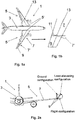
- Embodiments of the invention will now be described, by way of example only, with reference to the accompanying drawings, in which:
-
Figure 1a is a plan view of an example aircraft having a wing according to the invention; -
Figure 1b is a close-up view of the tip of the wing of the aircraft ofFigure 1a ; -
Figure 2a is a partial front view of the aircraft ofFigure 1a , showing various positions of a moveable wing tip; -
Figure 2b is a close-up front view of the wing tip joint in three different positions relative to a root part of the wing; -
Figure 3 is a close-up front view of an example wing tip joint having a double hinge, in two different positions relative to a root part of the wing; -
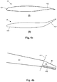
Figure 4a is a cross section through an example tip part of an example wing according to the invention, in two different configurations; -
Figure 4b is a plan view of the example wing ofFigure 4a ; -
Figure 5 is a partial cross-section through an example tip part of an example wing according to the invention, in two different configurations; -
Figure 6 is a top view of an example heating system of an example wing according to the invention; and -
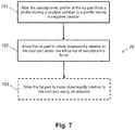
Figure 7 is a flow chart illustrating an example method of recovering a wing tip from a load-alleviating configuration to a flight configuration according to the invention. - Each example wing according to the invention has a fixed root part hingedly connected to a moveable tip part. The tip part is configured to pivot relative to the root part about a substantially horizontal axis, between a load-alleviating configuration in which the tip part is oriented relative to the root part such that at least one of the upper and lower surface of the tip part is positioned away from the respective surface of the root part and a flight configuration in which the upper and lower surfaces of the tip part are continuations of the upper and lower surfaces of the root part. In each example wing according to the invention the shape of the tip part is controllably switchable between a cruise shape in which the tip part has positive camber and a recovery shape in which the tip part has negative camber. The example wings according to the invention seek to reduce or eliminate the force required by an actuator to move the tip part from the load-alleviating configuration to the flight configuration.
-
Figure 1a is a plan view of anexample aircraft 1 according to the invention. The aircraft comprises acentral fuselage 3 and twomain wings 5 extending outwardly from respective wing roots 5'. Eachwing 5 comprises afixed root part 7 and amoveable tip part 9, in the form of a planar wing tip extension. Thetip part 9 is rotatably mounted about ahinge 11 that is orientated perpendicular to theswept mid-chord axis 13. Thishinge 11, is thus non-parallel to the line of flight direction (the line of flight direction being shown inFigure 1b for comparison). - Referring now to
Figures 2a and2b , thetip part 9 is rotatable about thehinge 11 from a flight configuration to a load alleviating configuration. In the flight configuration, thetip part 9 is an extension of thefixed root part 7. Accordingly the upper and lower surfaces of theroot part 7 are continuous with the upper and lower surfaces of the tip part 9 (seeFigure 2b(i) and the lowermost position inFigure 2a ). The leading and trailing edges of theroot part 7 are also continuous with the respective leading and trailing edges of the tip part 9 (seeFigures 1a and 1b ). Such an arrangement is beneficial as it provides a relatively large wing span, thereby providing an aerodynamically efficient aircraft. However a large span can result in correspondingly large loads on thewing 5, particularly a large wing root bending moment, especially during high load events such a gusts or extreme manoeuvres. Thewing 5 must be sized to cope with these maximum loads, which can result in a relatively heavy wing. The ability of thetip part 9 to move to the load alleviating configuration (seeFigures 2a and2b(ii) ) seeks to address that problem. - As shown in
Figure 2b(ii) and the middle position inFigure 2a , the tip part is rotatable, upwards, such that the lower surfaces between thefixed root part 7 and thetip part 9 are no longer continuous with one another. Furthermore, since thehinge 11 is angled with respect to the streamwise direction, when thetip part 9 rotates upwardly its mean incidence is reduced. In this configuration the loads on thewing 5 that are generated by thetip part 9 are significantly reduced. Thetip part 9 is moveable to this configuration during flight (described in more detail below). By providing this load alleviation function during flight, the maximum load the wing needs to be designed for may be reduced, and thus thewing 5 can be made relatively lightweight. - As used in this specification, the terms "upwards", "upwardly, "downwards", "downwardly", and the like are defined relative to the structure of the aircraft. Thus, "up" and "down" will align with the vertical direction when the aircraft is flying horizontally or is on the ground, but in some scenarios (such as when an aircraft is executing a banked turn), the up and down directions will not align with the vertical direction.
- The
tip part 9 may also be configurable to a ground configuration in which thetip part 9 is rotated yet further, to a substantially upright position (shown inFigure 2b(iii) and the upright position inFigure 2a ). Thetip part 9 is moveable to the ground configuration when theaircraft 1 is on the ground. When thetip part 9 is in the ground configuration the span of theaircraft 1 is sufficiently small to meet airport compatibility gate limits. Thus, theaircraft 1 can have a large span (exceeding gate limits) during flight, but is still able to comply with gate limits when on the ground. - Movement of the
tip part 9 between the flight configuration and the ground configuration may be effected by an actuator. For example, theaircraft 1 may comprise a motor connected to a drive shaft that forms the shaft of thehinge 11. The motor is arranged to rotate the drive shaft such that thetip part 9 moves from the flight configuration (seeFigure 2b ) to the ground configuration (seeFigure 2d ) by actuation of the motor 15. This typically occurs shortly after landing to enable the aircraft to comply with airport gate limits. The motor may also be arranged to effect this movement in reverse before take-off, to move thetip part 9 from the ground configuration to the flight configuration, once the aircraft has cleared the gate. - When the
aircraft 1 is flying and thetip part 9 is in the flight configuration, there tends to be a significant force on the tip part 9 (typically upwards). Thewing 5 may therefore comprise a locking or restraining mechanism to maintain thetip part 9 in the flight configuration during flight. An example of a suitable locking/restraining mechanism is described inWO/2017/118832 . The locking/restraining mechanism is releasable in the event of an unusually large load being experienced by the tip part 9 (e.g. due to a strong gust of wind), to enable thetip part 9 to move to the load alleviating configuration. This means thewing 5 can avoid being subjected to high gust loadings. This in turn may enable thewing 5 to have a relatively large span, without necessarily having to incur the associated weight penalty, because it can be designed for a lower magnitude of maximum load. Thetip part 9 may be moveable to the load alleviating configuration purely under the action of aerodynamic force acting on it during flight, or under the gust loads. Alternatively, in some examples thewing 5 comprises a mechanism (such as a pre-loaded spring) for assisting the movement of thetip part 9 from the flight configuration to the load-alleviating configuration. - In some examples, as illustrated by
Figure 3 , thehinge 11 may be a double hinge for allowing both upward and downward rotation of thetip part 9 to the load alleviating configuration (only the downward rotation being illustrated inFigure 3 , and the upward rotation being as perFigure 2b ). Such an arrangement enables both positive-g and negative-g loads to be alleviated. - As soon as the conditions causing the high load on the
tip part 9 are no longer present, it is desirable to move thetip part 9 back to the flight configuration to regain the efficiency benefits of a large wing span. However; the aerodynamic force on thetip part 9 as a result of its aerofoil shape may generally act to resist it moving back to the flight configuration. The force required to move thetip part 9 from the gust-alleviating configuration to the flight configuration during flight may be significantly greater than the force required to move thetip part 9 from the flight configuration to the ground configuration when the aircraft is on the ground. An actuator sized for moving thetip part 9 between the flight configuration and the ground configuration when theaircraft 1 is on the ground will therefore generally not be able to exert enough force to move thetip part 9 from the load-alleviating configuration to the flight configuration during flight. - To reduce or eliminate the force required to move the
tip part 9 from the load-alleviating configuration to the flight configuration during flight, the shape of thetip part 9 is controllably switchable between a cruise shape in which thetip part 9 has positive camber, and a recovery shape in which thetip part 9 has negative camber. -
Figures 4a and 4b show anexample tip part 49, attached to anexample root part 47. Thetip part 49 androot part 47 are relatively pivotable about ahinge line 411 and have the same features as theexample tip part 9 and rootpart 7 ofFigures 1-3 , except that thetip part 49 is backswept relative to theroot part 47. Thetip part 49 has aleading edge region 491 and a trailingedge region 492.Figure 4a shows the cross-sectional profile of thetip part 9 in the cruise shape (part (i)) and in the recovery shape (part (ii)) andFigure 4b is a plan view of thetip part 49 androot part 47 in the flight configuration. In the recovery shape the trailingedge 492 of thetip part 49 is deflected upwardly (relative to a normal operational orientation of the tip part 49) relative to its position in the cruise configuration. The shaded area of thetip part 49 onFigure 4b corresponds to the region of the tip part which experiences a change during a switch from the cruise shape to the recovery shape and vice versa. - When the
tip part 49 is in the load alleviating configuration shown inFigure 2b(i) and in the cruise shape, as a result of the positive camber of thetip part 49, aerodynamic forces on thetip part 49 act to resist its return to the flight configuration. However; switching thetip part 49 to the negative camber recovery shape whilst thetip part 49 is in the load alleviating configuration causes the direction of the aerodynamic force to be generally downward rather than upward. Thetip part 49 may thereby be returned to the flight configuration mostly or entirely under the action of aerodynamic force. An actuator for driving pivoting movement of thetip part 49 may therefore be sized such that the maximum torque able to be generated by the actuator is less than a torque expected to be required to move thetip part 49 from the load-alleviating configuration to the flight configuration during flight when the tip part has the cruise shape. Such an actuator may be sized to generate a torque sufficient for driving movement of thetip part 49 between the ground configuration and the flight configuration when the aircraft is on the ground. In some examples, e.g. examples in which the wing span of the aircraft is small enough that it is not required to be able to fold the tip parts when on the ground, there may not be any actuator provided to drive pivoting movement of thetip part 49. -
Figures 5 and 6 show a particular implementation of anexample tip part 59 according to the invention.Figure 5 shows cross-sections through the trailingedge 592 of thetip part 59 in the cruise shape (part (i)) and in the recovery shape (part (ii)). Thetip part 59 is constructed such that the switching of thetip part 59 between the cruise shape and the recovery shape is dependent on the temperature of at least a region of thetip part 59. In particular, the trailingedge 592 of thetip part 59 comprises adeformable component 593 that is controllably switchable between a first shape and a second shape. Thedeformable component 593 may be formed, for example, from a shape memory alloy (SMA) material. Thetip part 59 is configured such that thedeformable component 593 having the first shape causes thetip part 59 to have the cruise shape and thedeformable component 593 having the second shape causes thetip part 59 to have the recovery shape. Thedeformable component 593 may extend across substantially the entire span of the tip part (e.g. such that it is present across the entire hatched area shown inFigure 4b ), or it may comprise multiple discrete portions distributed along the span. - In the particular example of
Figure 5 the first shape of the deformable component 593 (illustrated byFigure 5(i) ) is substantially planar. Thedeformable component 593 is oriented within thetip part 59 such that when thedeformable component 593 has the first shape it is substantially parallel to the chordwise and spanwise axes of the wing in which thetip part 59 is comprised. The second shape of the deformable component 593 (illustrated byFigure 5(ii) ) is a deformed plane that is bent such that a leading edge of thedeformable component 593 is in the plane of the first shape and a trailing edge extends out of the plane of the first shape. Thus, switching from the first shape to the second shape involves the trailing edge of thedeformable component 593 moving upwardly and becoming angled relative to the leading edge, whilst the position and orientation of the leading edge remains the same. - The chordwise dimension of the deformable component (in the first shape) may be selected to enable a desired amount of upwards deflection of the trailing edge in the second shape. It is generally possible to achieve a greater amount of upwards deflection with a longer chordwise dimension. In general, the chordwise dimension of the deformable component may be 20-50% of the total chord length of the
tip part 59 at any given spanwise location. - The
deformable component 593 is sandwiched between twoportions 594 of flexible material. Theflexible portions 594 are aerodynamically shaped to form the trailing edge of an aerofoil structure. Theflexible portions 594 together with thedeformable component 593 form the trailingedge region 592 of thetip part 59. Theflexible portions 594 may be made from any suitable flexible material such as an elastomeric material. The flexible material may be selected to be stiff enough to maintain an aerodynamic shape during flight, in both shapes of the tip part, but flexible enough to be readily deformed by a shape change of thedeformable component 593. The rest of the tip part 59 (that is the leading edge region and the intermediate region between the leading edge region and the trailing edge region 592) is substantially rigid and may have any suitable construction. The trailingedge region 592 may be connected to the rest of thetip part 59 by any suitable mechanism. In some examples a flexible skin may encase thewhole tip part 59, to ensure a continuous aerodynamic surface and minimize any steps or gaps where the trailingedge region 592 joins to the rest of thetip part 59. - The
deformable component 593 is configured to switch from the first shape to the second shape in response to the temperature of the deformable component exceeding a predefined threshold temperature. This may be achieved, for example, by forming the deformable component from a two-way shape memory alloy (SMA) trained to remember the first shape at low temperatures (i.e. temperatures below the predefined threshold temperature) and the second shape at high temperatures (i.e. temperatures above the predefined threshold temperature). The threshold temperature is greater than any temperature that could naturally be reached by the deformable component during operation of an aircraft in which thetip part 59 is comprised. The exact material composition of the SMA may be selected in dependence on specific features of the particular application (e.g. the size of the tip part, the stiffness of the portions of flexible material, the size and shape of the deformable component, and the like). In order to controllable raise the temperature of thedeformable component 593 to above the threshold temperature, thetip part 59 comprises a heater (not shown). The heater may be based on any suitable technology. -
Figure 6 shows a furtherexample tip part 69 androot part 67 having a heater suitable for increasing the temperature of a deformable component comprised in thetip part 69. Theroot part 67 has the same features as theexample root part 47 described above. Thetip part 69 is pivotable about ahinge line 611 relative to theroot part 67 and has the same features as theexample tip part 59 described above. The heater comprises anelectrical heating element 695 configured to receive control signals from acontroller 696 that is remote from theheating element 695. By "remote" it is meant that the controller is not comprised in thetip part 69. Thecontroller 696 may be, for example, in theroot part 67 as shown inFigure 6 , or it may be elsewhere on the aircraft. Theheating element 695 is a resistive heating element. Thetip part 69 comprises a deformable component having the same features as thedeformable component 593, which is present in the dashed region. Theheating element 695 is arranged such that the deformable component is substantially evenly heated across its full area. - In the illustrated example the
heating element 695 is connected to thecontroller 696 by a wired electrical connection for transmitting electrical signals between the controller and theheating element 695. The wired connection provides both electrical power and control signals to theheating element 695. The wired electrical connection is configured to remain intact in all possible relative positions of thetip part 69 and theroot part 67. Other examples are possible in which the connection between thecontroller 696 and theheating element 695 is wireless. In such examples control and/or power signals may be transmitted between thecontroller 696 and theheating element 695 using any suitable wireless communications medium, such as RF waves or infrared waves. In some examples theheating element 695 receives electrical power from a local source provided on thetip part 69, such as a battery or solar cell. - The
controller 696 is configured to activate theheating element 695 when it is desired to switch thetip part 69 from the cruise shape to the recovery shape. Thecontroller 696 may be configured to operate theheating element 695 to maintain the temperature of the deformable component above the threshold temperature until it is desired to switch thetip part 69 back to the cruise shape from the recovery shape. Thecontroller 696 may be configured to selectively operate theheating element 695 in a temperature increasing mode, in which the rate of transfer of thermal energy to the deformable component is relatively higher, and in a temperature maintenance mode in which the rate of transfer of thermal energy to the deformable component is relatively lower. - The
tip part 69 may comprise a temperature sensor configured to measure the current temperature of the deformable component and to provide temperature information to thecontroller 696, in which case thecontroller 696 may control the heating element 695 (e.g. by selecting a mode of operation and/or varying an amount of electrical energy supplied to the heating element 695) based on the provided temperature information. Thecontroller 696 may also be configured to receive configuration information about a current configuration of the tip part 69 (e.g. whether it is in the load-alleviating configuration or the flight configuration) and/or information about a current shape of the tip part 69 (e.g. whether it has the cruise shape or the recovery shape) and to control theheating element 695 based on such configuration information. The configuration information may be provided to thecontroller 696 by any suitable type of sensor(s). Thecontroller 696 may also be configured to receive load information about a current load being experienced by thetip part 69 and to control theheating element 695 based on such load information. The load information may be provided to thecontroller 696 by any suitable type of sensor(s). In some examples thecontroller 696 may additionally be configured to receive control signals from another part of the aircraft, e.g. the cockpit, to enable direct control of the tip part shape by flight crew. Thecontroller 696 may be configured to control theheating element 695 based on any combination of temperature information, configuration information, load information and control signals. -
Figure 7 is a flow chart illustrating anexample method 70 of moving, during flight, a tip part of an aircraft wing from an upwardly-folded position relative to a root part of the aircraft wing to a non-folded position. The method may be implemented by any of the example aircraft wings according to the invention, including the examples specifically described above. The upwardly-folded position may correspond to, for example, the load-alleviating configuration of the example wings described above and the non-folded position may correspond to the flight configuration of those example wings. - In a
first block 701, the aerodynamic profile of the tip part is altered from a profile having a positive camber to a profile having a negative camber. Altering the aerodynamic profile of the tip part may comprise switching the tip part from a cruise shape to a recovery shape, as described above in relation to the example aircraft wings ofFigures 4-6 . Altering the aerodynamic profile of the tip part may comprise raising the temperature of a shape memory alloy component of the tip part until the shape memory alloy component is caused to transition from a first shape corresponding to the positive camber aerodynamic profile to a second shape corresponding to the negative camber aerodynamic profile.Block 701 may be performed in response to the detection of certain environmental conditions, such as the presence or absence of a particular type of load on the tip part.Block 701 may be performed in response to a detection that the tip part is in the upwardly-folded position. - In a
second block 702, the tip part is allowed to rotate downwardly relative to the root part under the influence of aerodynamic force. The aerodynamic force acts downwardly on the tip part and is generated by the interaction of the oncoming air flow with the negative camber of the tip part. The magnitude of the aerodynamic force depends on factors such as the speed of the airflow over the tip part, and the degree of the negative camber. Allowing the tip part to rotate downwardly may comprise simply not preventing the downwards rotation, at least until the tip part reaches the non-folded position. The downwards rotation of the tip part may be halted, for example by a structural stop or a braking mechanism, when the tip part is in the non-folded position. In some examples, allowing the tip part to rotate downwardly may comprise controlling the rate of the downwards rotation, e.g. using a damping mechanism. - In some examples, the
method 70 comprises anoptional block 703, in which the tip part is driven to move downwardly relative to the root part using an actuator.Block 703 may be performed simultaneously withblock 702, such that the aerodynamic force provides a portion of the total torque required to rotate the tip part from the upwardly-folded position to the non-folded position, and the actuator provides the rest of the required torque. Alternatively or additionally, block 703 may be performed before or afterblock 702, such that the downwards rotation is initially driven by the actuator, but completed by aerodynamic force, or vice versa. In any case, the torque provided by the actuator is less than the total torque required to rotate the tip part from the upwardly-folded position to the non-folded position. - In some examples, the
method 70 may be partially implemented by a controller on the aircraft. The controller may be, for example, a controller of a heating system such as theexample controller 696 described above. The controller may be part of an avionics system of the aircraft. - Although the invention has been described above with reference to one or more preferred examples or embodiments, it will be appreciated that various changes or modifications may be made without departing from the scope of the invention as defined in the appended claims.
- Where the term "or" has been used in the preceding description, this term should be understood to mean "and/or", except where explicitly stated otherwise.
Claims (15)
- An aircraft wing having a fixed root part hingedly connected to a moveable tip part, wherein the tip part is configured to pivot relative to the root part about a substantially horizontal axis, between a load-alleviating configuration in which the tip part is oriented relative to the root part such that at least one of the upper and lower surface of the tip part is positioned away from the respective surface of the root part and a flight configuration in which the upper and lower surfaces of the tip part are continuations of the upper and lower surfaces of the root part, and wherein the shape of the tip part is controllably switchable between a cruise shape in which the tip part has positive camber and a recovery shape in which the tip part has negative camber.
- An aircraft wing according to claim 1, wherein in the recovery shape a trailing edge of the tip part is deflected upwardly relative to its position in the cruise shape.
- An aircraft wing according to claim 1 or claim 2, wherein the switching of the tip part between the cruise shape and the recovery shape is dependent on the temperature of at least a region of the tip part.
- An aircraft wing according to claim 1 or claim 2, wherein the tip part comprises a deformable component that is controllably switchable between a first shape and a second shape, and wherein the tip part is configured such that the deformable component having the first shape causes the tip part to have the cruise shape and the deformable component having the second shape causes the tip part to have the recovery shape.
- An aircraft wing according to claim 4, wherein the first shape of the deformable component is substantially planar, and wherein the deformable component is oriented within the tip part such that when the deformable component has the first shape it is substantially parallel to the chordwise and spanwise axes of the wing.
- An aircraft wing according to claim 5, wherein the second shape of the deformable component is a deformed plane that is bent such that a leading edge of the deformable component is in the plane of the substantially planar first shape and a trailing edge of the deformable component extends out of the plane of the substantially planar first shape.
- An aircraft wing according to any of claims 4 to 6, wherein the deformable component is comprised in a trailing edge of the tip part.
- An aircraft wing according to claim 7, wherein the trailing edge comprises the deformable component sandwiched between two portions of flexible material, and optionally wherein the portions of flexible material are aerodynamically shaped to form the trailing edge of an aerofoil structure.
- An aircraft wing according to any of claims 4 to 8, wherein the deformable component is configured to switch from the first shape to the second shape in response to the temperature of the deformable component exceeding a predefined threshold temperature.
- An aircraft wing according to claim 9, wherein the tip part further comprises a heater configured to increase the temperature of the deformable component, and optionally wherein the heater comprises an electrical heating element configured to receive control signals from a remote controller.
- An aircraft wing according to claim 10, wherein the wing comprises an electrical connection between the root part and the tip part for supplying power and/or control signals to the heating element.
- An aircraft wing according to any preceding claim, further comprising an actuator for driving pivoting movement of the tip part, wherein the maximum torque able to be generated by the actuator is less than a torque expected to be required to move the tip part from the load-alleviating configuration to the flight configuration during flight when the tip part has the cruise shape.
- A method of moving, during flight, a tip part of an aircraft wing from an upwardly-folded position relative to a root part of the aircraft wing to a non-folded position, the method comprising:altering the aerodynamic profile of the tip part from a profile having a positive camber to a profile having a negative camber; andallowing the tip part to rotate downwardly relative to the root part under the influence of aerodynamic force.
- A method according to claim 13, further comprising driving the tip part to move downwardly relative to the root part using an actuator, simultaneously with allowing the tip part to rotate downwardly under the influence of aerodynamic force.
- A method according to claim 13 or claim 14, wherein altering the aerodynamic profile of the tip part comprises raising the temperature of a shape memory alloy component of the tip part until the shape memory alloy component is caused to transition from a first shape corresponding to the positive camber aerodynamic profile to a second shape corresponding to the negative camber aerodynamic profile.
Applications Claiming Priority (1)
| Application Number | Priority Date | Filing Date | Title |
|---|---|---|---|
| GB1817770.9A GB2578587A (en) | 2018-10-31 | 2018-10-31 | Aircraft wing tips |
Publications (1)
| Publication Number | Publication Date |
|---|---|
| EP3647181A1 true EP3647181A1 (en) | 2020-05-06 |
Family
ID=64655359
Family Applications (1)
| Application Number | Title | Priority Date | Filing Date |
|---|---|---|---|
| EP19203006.2A Withdrawn EP3647181A1 (en) | 2018-10-31 | 2019-10-14 | Aircraft wing tips |
Country Status (3)
| Country | Link |
|---|---|
| US (1) | US11225315B2 (en) |
| EP (1) | EP3647181A1 (en) |
| GB (1) | GB2578587A (en) |
Cited By (2)
| Publication number | Priority date | Publication date | Assignee | Title |
|---|---|---|---|---|
| EP4682049A1 (en) * | 2024-07-18 | 2026-01-21 | Airbus Operations Limited | Cable harness sleeves |
| EP4686649A1 (en) * | 2024-07-29 | 2026-02-04 | Airbus Operations Limited | Wing assembly |
Families Citing this family (11)
| Publication number | Priority date | Publication date | Assignee | Title |
|---|---|---|---|---|
| GB202008876D0 (en) | 2020-06-11 | 2020-07-29 | Rolls Royce Plc | Aircraft |
| CN112960108A (en) * | 2021-04-07 | 2021-06-15 | 西北工业大学 | Folding wing unfolding mechanism based on shape memory alloy driving and unmanned aerial vehicle |
| KR20230021842A (en) * | 2021-08-06 | 2023-02-14 | 이창만 | Aircraft wing |
| CN114291249B (en) * | 2021-12-31 | 2023-08-04 | 中国飞机强度研究所 | Variable-thickness wing structure |
| US11932390B2 (en) * | 2022-04-15 | 2024-03-19 | Toyota Motor Engineering & Manufacturing North America, Inc. | Wing shape control |
| US11939055B2 (en) * | 2022-04-15 | 2024-03-26 | Toyota Motor Engineering & Manufacturing North America, Inc. | Winglets with passive aeroelastic tailoring |
| CN115452308B (en) * | 2022-11-09 | 2023-03-14 | 中国空气动力研究与发展中心高速空气动力研究所 | Deflection angle adjustable structure for measuring control surface manipulation efficiency in wind tunnel |
| CN115675833A (en) * | 2022-12-29 | 2023-02-03 | 中国空气动力研究与发展中心设备设计与测试技术研究所 | Polymorphic deformation wing based on active deformation skin |
| US20240253765A1 (en) * | 2023-01-31 | 2024-08-01 | Rohr, Inc. | Folding wings for an aircraft |
| GB2630990B (en) * | 2023-06-16 | 2026-01-28 | Airbus Operations Ltd | An aircraft wing with a moveable wing tip |
| GB2636846A (en) * | 2023-12-22 | 2025-07-02 | Airbus Operations Ltd | An aircraft wing with a wing tip device |
Citations (6)
| Publication number | Priority date | Publication date | Assignee | Title |
|---|---|---|---|---|
| US5662294A (en) * | 1994-02-28 | 1997-09-02 | Lockheed Martin Corporation | Adaptive control surface using antagonistic shape memory alloy tendons |
| US5988563A (en) * | 1997-12-30 | 1999-11-23 | Mcdonnell Douglas Corporation | Articulating winglets |
| EP1531126B1 (en) * | 2003-11-11 | 2007-02-07 | Airbus UK Limited | Wing tip device |
| US20160233410A1 (en) * | 2013-12-16 | 2016-08-11 | U.S.A. As Represented By The Administrator Of The National Aeronautics And Space Administration | Self-Latching Piezocomposite Actuator |
| WO2017118832A1 (en) | 2016-01-05 | 2017-07-13 | Airbus Operations Limited | An aircraft wing with a moveable wing tip device for load alleviation |
| US20180043985A1 (en) * | 2016-08-12 | 2018-02-15 | Aviation Partners, Inc. | Shape Adaptive Airfoil |
Family Cites Families (5)
| Publication number | Priority date | Publication date | Assignee | Title |
|---|---|---|---|---|
| US5114104A (en) * | 1990-10-01 | 1992-05-19 | The United States Of America As Represented By The Secretary Of The Navy | Articulated control surface |
| ES2728917T3 (en) * | 2014-06-12 | 2019-10-29 | Airbus Operations Gmbh | Output device for progressive variation of an aerodynamic profile |
| US20170073062A1 (en) * | 2015-09-12 | 2017-03-16 | Gregory S. Firth | Variable Geometry Wingtip |
| US9873502B2 (en) * | 2016-01-05 | 2018-01-23 | The Boeing Company | Controlling airloads on aircraft folding wing tips |
| GB2554892A (en) * | 2016-10-12 | 2018-04-18 | Airbus Operations Ltd | Aircraft wing with aileron |
-
2018
- 2018-10-31 GB GB1817770.9A patent/GB2578587A/en not_active Withdrawn
-
2019
- 2019-10-14 EP EP19203006.2A patent/EP3647181A1/en not_active Withdrawn
- 2019-10-30 US US16/668,814 patent/US11225315B2/en active Active
Patent Citations (6)
| Publication number | Priority date | Publication date | Assignee | Title |
|---|---|---|---|---|
| US5662294A (en) * | 1994-02-28 | 1997-09-02 | Lockheed Martin Corporation | Adaptive control surface using antagonistic shape memory alloy tendons |
| US5988563A (en) * | 1997-12-30 | 1999-11-23 | Mcdonnell Douglas Corporation | Articulating winglets |
| EP1531126B1 (en) * | 2003-11-11 | 2007-02-07 | Airbus UK Limited | Wing tip device |
| US20160233410A1 (en) * | 2013-12-16 | 2016-08-11 | U.S.A. As Represented By The Administrator Of The National Aeronautics And Space Administration | Self-Latching Piezocomposite Actuator |
| WO2017118832A1 (en) | 2016-01-05 | 2017-07-13 | Airbus Operations Limited | An aircraft wing with a moveable wing tip device for load alleviation |
| US20180043985A1 (en) * | 2016-08-12 | 2018-02-15 | Aviation Partners, Inc. | Shape Adaptive Airfoil |
Cited By (2)
| Publication number | Priority date | Publication date | Assignee | Title |
|---|---|---|---|---|
| EP4682049A1 (en) * | 2024-07-18 | 2026-01-21 | Airbus Operations Limited | Cable harness sleeves |
| EP4686649A1 (en) * | 2024-07-29 | 2026-02-04 | Airbus Operations Limited | Wing assembly |
Also Published As
| Publication number | Publication date |
|---|---|
| GB2578587A (en) | 2020-05-20 |
| GB201817770D0 (en) | 2018-12-19 |
| US11225315B2 (en) | 2022-01-18 |
| US20200172227A1 (en) | 2020-06-04 |
Similar Documents
| Publication | Publication Date | Title |
|---|---|---|
| US11225315B2 (en) | Aircraft wing tips | |
| CA2857892C (en) | Adaptive trailing edge actuator system and method | |
| EP3862261B1 (en) | An aircraft wing with a moveable wing tip device for load alleviation | |
| EP2456663B1 (en) | Shape-changing control surface | |
| EP2727826B1 (en) | Hinged raked wing tip | |
| EP2371707B1 (en) | Aircraft directional control and stabilizing surface | |
| EP0937641B1 (en) | Flight controls with automatique balance | |
| US8356770B2 (en) | Tail-mounted pointable solar panels for solar-powered aircraft | |
| US20160176506A1 (en) | Lifting surfaces and associated method | |
| US6164599A (en) | Aerofoil profile with variable profile adaptation | |
| WO1999015403A3 (en) | Extendible leading edge flap | |
| EP3774528B1 (en) | Wing tips and wing tip construction and design methods | |
| WO2015065551A1 (en) | Aircraft wing structure and control system | |
| US9731812B2 (en) | Flap mechanism and associated method | |
| WO2007117260A2 (en) | Aircraft with belly flaps | |
| US20240158071A1 (en) | Aircraft wing | |
| CN113602476A (en) | Continuous deformation structure and deformation method for wing trailing edge | |
| EP1883577B1 (en) | Concept of a variable winglet for lateral load reduction for combined lateral and vertical load reduction, and for improving the performance of means of locomotion | |
| GB2583499A (en) | Aircraft wing with a moveable wing tip for load alleviation | |
| US12509220B2 (en) | Aircraft wing with a moveable wing tip | |
| CN109018330A (en) | Vertical landing unmanned plane | |
| US12377959B2 (en) | Aircraft wing trailing edge device | |
| US20220177114A1 (en) | Airfoil system | |
| CN218317283U (en) | Trailing edge cracking type wing | |
| CN111470039A (en) | Rotor wing control system suitable for heavy-load type rotary wing aircraft with stepped hub |
Legal Events
| Date | Code | Title | Description |
|---|---|---|---|
| PUAI | Public reference made under article 153(3) epc to a published international application that has entered the european phase |
Free format text: ORIGINAL CODE: 0009012 |
|
| STAA | Information on the status of an ep patent application or granted ep patent |
Free format text: STATUS: THE APPLICATION HAS BEEN PUBLISHED |
|
| AK | Designated contracting states |
Kind code of ref document: A1 Designated state(s): AL AT BE BG CH CY CZ DE DK EE ES FI FR GB GR HR HU IE IS IT LI LT LU LV MC MK MT NL NO PL PT RO RS SE SI SK SM TR |
|
| AX | Request for extension of the european patent |
Extension state: BA ME |
|
| STAA | Information on the status of an ep patent application or granted ep patent |
Free format text: STATUS: REQUEST FOR EXAMINATION WAS MADE |
|
| 17P | Request for examination filed |
Effective date: 20201019 |
|
| RBV | Designated contracting states (corrected) |
Designated state(s): AL AT BE BG CH CY CZ DE DK EE ES FI FR GB GR HR HU IE IS IT LI LT LU LV MC MK MT NL NO PL PT RO RS SE SI SK SM TR |
|
| STAA | Information on the status of an ep patent application or granted ep patent |
Free format text: STATUS: EXAMINATION IS IN PROGRESS |
|
| 17Q | First examination report despatched |
Effective date: 20210520 |
|
| STAA | Information on the status of an ep patent application or granted ep patent |
Free format text: STATUS: THE APPLICATION IS DEEMED TO BE WITHDRAWN |
|
| 18D | Application deemed to be withdrawn |
Effective date: 20251023 |