EP3647125A1 - Smart door apparatus of a construction machine - Google Patents
Smart door apparatus of a construction machine Download PDFInfo
- Publication number
- EP3647125A1 EP3647125A1 EP19207067.0A EP19207067A EP3647125A1 EP 3647125 A1 EP3647125 A1 EP 3647125A1 EP 19207067 A EP19207067 A EP 19207067A EP 3647125 A1 EP3647125 A1 EP 3647125A1
- Authority
- EP
- European Patent Office
- Prior art keywords
- harness
- door
- axial direction
- smart
- hinge
- Prior art date
- Legal status (The legal status is an assumption and is not a legal conclusion. Google has not performed a legal analysis and makes no representation as to the accuracy of the status listed.)
- Granted
Links
Images




Classifications
-
- B—PERFORMING OPERATIONS; TRANSPORTING
- B60—VEHICLES IN GENERAL
- B60R—VEHICLES, VEHICLE FITTINGS, OR VEHICLE PARTS, NOT OTHERWISE PROVIDED FOR
- B60R16/00—Electric or fluid circuits specially adapted for vehicles and not otherwise provided for; Arrangement of elements of electric or fluid circuits specially adapted for vehicles and not otherwise provided for
- B60R16/02—Electric or fluid circuits specially adapted for vehicles and not otherwise provided for; Arrangement of elements of electric or fluid circuits specially adapted for vehicles and not otherwise provided for electric constitutive elements
- B60R16/0207—Wire harnesses
- B60R16/0215—Protecting, fastening and routing means therefor
-
- E—FIXED CONSTRUCTIONS
- E05—LOCKS; KEYS; WINDOW OR DOOR FITTINGS; SAFES
- E05D—HINGES OR SUSPENSION DEVICES FOR DOORS, WINDOWS OR WINGS
- E05D11/00—Additional features or accessories of hinges
-
- B—PERFORMING OPERATIONS; TRANSPORTING
- B60—VEHICLES IN GENERAL
- B60R—VEHICLES, VEHICLE FITTINGS, OR VEHICLE PARTS, NOT OTHERWISE PROVIDED FOR
- B60R25/00—Fittings or systems for preventing or indicating unauthorised use or theft of vehicles
- B60R25/30—Detection related to theft or to other events relevant to anti-theft systems
- B60R25/34—Detection related to theft or to other events relevant to anti-theft systems of conditions of vehicle components, e.g. of windows, door locks or gear selectors
-
- B—PERFORMING OPERATIONS; TRANSPORTING
- B60—VEHICLES IN GENERAL
- B60J—WINDOWS, WINDSCREENS, NON-FIXED ROOFS, DOORS, OR SIMILAR DEVICES FOR VEHICLES; REMOVABLE EXTERNAL PROTECTIVE COVERINGS SPECIALLY ADAPTED FOR VEHICLES
- B60J5/00—Doors
- B60J5/04—Doors arranged at the vehicle sides
- B60J5/0468—Fixation or mounting means specific for door components
-
- B—PERFORMING OPERATIONS; TRANSPORTING
- B60—VEHICLES IN GENERAL
- B60R—VEHICLES, VEHICLE FITTINGS, OR VEHICLE PARTS, NOT OTHERWISE PROVIDED FOR
- B60R16/00—Electric or fluid circuits specially adapted for vehicles and not otherwise provided for; Arrangement of elements of electric or fluid circuits specially adapted for vehicles and not otherwise provided for
- B60R16/02—Electric or fluid circuits specially adapted for vehicles and not otherwise provided for; Arrangement of elements of electric or fluid circuits specially adapted for vehicles and not otherwise provided for electric constitutive elements
- B60R16/0207—Wire harnesses
-
- B—PERFORMING OPERATIONS; TRANSPORTING
- B60—VEHICLES IN GENERAL
- B60R—VEHICLES, VEHICLE FITTINGS, OR VEHICLE PARTS, NOT OTHERWISE PROVIDED FOR
- B60R16/00—Electric or fluid circuits specially adapted for vehicles and not otherwise provided for; Arrangement of elements of electric or fluid circuits specially adapted for vehicles and not otherwise provided for
- B60R16/02—Electric or fluid circuits specially adapted for vehicles and not otherwise provided for; Arrangement of elements of electric or fluid circuits specially adapted for vehicles and not otherwise provided for electric constitutive elements
- B60R16/03—Electric or fluid circuits specially adapted for vehicles and not otherwise provided for; Arrangement of elements of electric or fluid circuits specially adapted for vehicles and not otherwise provided for electric constitutive elements for supply of electrical power to vehicle subsystems or for
-
- B—PERFORMING OPERATIONS; TRANSPORTING
- B60—VEHICLES IN GENERAL
- B60R—VEHICLES, VEHICLE FITTINGS, OR VEHICLE PARTS, NOT OTHERWISE PROVIDED FOR
- B60R25/00—Fittings or systems for preventing or indicating unauthorised use or theft of vehicles
- B60R25/10—Fittings or systems for preventing or indicating unauthorised use or theft of vehicles actuating a signalling device
-
- B—PERFORMING OPERATIONS; TRANSPORTING
- B62—LAND VEHICLES FOR TRAVELLING OTHERWISE THAN ON RAILS
- B62D—MOTOR VEHICLES; TRAILERS
- B62D33/00—Superstructures for load-carrying vehicles
- B62D33/06—Drivers' cabs
-
- E—FIXED CONSTRUCTIONS
- E05—LOCKS; KEYS; WINDOW OR DOOR FITTINGS; SAFES
- E05D—HINGES OR SUSPENSION DEVICES FOR DOORS, WINDOWS OR WINGS
- E05D11/00—Additional features or accessories of hinges
- E05D11/0054—Covers, e.g. for protection
-
- E—FIXED CONSTRUCTIONS
- E05—LOCKS; KEYS; WINDOW OR DOOR FITTINGS; SAFES
- E05D—HINGES OR SUSPENSION DEVICES FOR DOORS, WINDOWS OR WINGS
- E05D11/00—Additional features or accessories of hinges
- E05D11/0081—Additional features or accessories of hinges for transmitting energy, e.g. electrical cable routing
-
- E—FIXED CONSTRUCTIONS
- E05—LOCKS; KEYS; WINDOW OR DOOR FITTINGS; SAFES
- E05D—HINGES OR SUSPENSION DEVICES FOR DOORS, WINDOWS OR WINGS
- E05D7/00—Hinges or pivots of special construction
-
- H—ELECTRICITY
- H02—GENERATION; CONVERSION OR DISTRIBUTION OF ELECTRIC POWER
- H02G—INSTALLATION OF ELECTRIC CABLES OR LINES, OR OF COMBINED OPTICAL AND ELECTRIC CABLES OR LINES
- H02G11/00—Arrangements of electric cables or lines between relatively-movable parts
-
- B—PERFORMING OPERATIONS; TRANSPORTING
- B60—VEHICLES IN GENERAL
- B60Y—INDEXING SCHEME RELATING TO ASPECTS CROSS-CUTTING VEHICLE TECHNOLOGY
- B60Y2200/00—Type of vehicle
- B60Y2200/40—Special vehicles
- B60Y2200/41—Construction vehicles, e.g. graders, excavators
-
- E—FIXED CONSTRUCTIONS
- E02—HYDRAULIC ENGINEERING; FOUNDATIONS; SOIL SHIFTING
- E02F—DREDGING; SOIL-SHIFTING
- E02F9/00—Component parts of dredgers or soil-shifting machines, not restricted to one of the kinds covered by groups E02F3/00 - E02F7/00
- E02F9/16—Cabins, platforms, or the like, for drivers
-
- E—FIXED CONSTRUCTIONS
- E05—LOCKS; KEYS; WINDOW OR DOOR FITTINGS; SAFES
- E05Y—INDEXING SCHEME ASSOCIATED WITH SUBCLASSES E05D AND E05F, RELATING TO CONSTRUCTION ELEMENTS, ELECTRIC CONTROL, POWER SUPPLY, POWER SIGNAL OR TRANSMISSION, USER INTERFACES, MOUNTING OR COUPLING, DETAILS, ACCESSORIES, AUXILIARY OPERATIONS NOT OTHERWISE PROVIDED FOR, APPLICATION THEREOF
- E05Y2900/00—Application of doors, windows, wings or fittings thereof
- E05Y2900/50—Application of doors, windows, wings or fittings thereof for vehicles
- E05Y2900/518—Application of doors, windows, wings or fittings thereof for vehicles for working vehicles
-
- E—FIXED CONSTRUCTIONS
- E05—LOCKS; KEYS; WINDOW OR DOOR FITTINGS; SAFES
- E05Y—INDEXING SCHEME ASSOCIATED WITH SUBCLASSES E05D AND E05F, RELATING TO CONSTRUCTION ELEMENTS, ELECTRIC CONTROL, POWER SUPPLY, POWER SIGNAL OR TRANSMISSION, USER INTERFACES, MOUNTING OR COUPLING, DETAILS, ACCESSORIES, AUXILIARY OPERATIONS NOT OTHERWISE PROVIDED FOR, APPLICATION THEREOF
- E05Y2900/00—Application of doors, windows, wings or fittings thereof
- E05Y2900/50—Application of doors, windows, wings or fittings thereof for vehicles
- E05Y2900/53—Type of wing
- E05Y2900/531—Doors
Definitions
- Example embodiments relate to a smart door apparatus of a construction machine. More particularly, example embodiments relate to a harness of a smart door apparatus in a construction machine.
- a smart door apparatus of a construction machine may include an actuator and a harness.
- the actuator may be installed at a door rotatably connected with a cabin of the construction machine via a hinge mechanism.
- the actuator may be configured to operate a locking apparatus of the door by signals of a smart key.
- the harness may be arranged in an axial direction of the hinge mechanism to supply electricity to the actuator.
- the smart door apparatus may further include an upper cover configured to cover the upper clamp, and a lower cover configured to cover the lower clamp.
- the smart door apparatus may further include a sealant configured to fill a space between the lower cover, the lower clamp and the lower end of the harness to fix the harness.
- the harness may be arranged on an outer surface of the door in the axial direction.
- the harness may enter into the door to be connected to the actuator.
- the smart door apparatus may further include at least one clip configured to fix the harness in the door to an inner surface of the door.
- spatially relative terms such as “beneath,” “below,” “lower,” “above,” “upper” and the like, may be used herein for ease of description to describe one element or feature's relationship to another element(s) or feature(s) as illustrated in the figures. It will be understood that the spatially relative terms are intended to encompass different orientations of the device in use or operation in addition to the orientation depicted in the figures. For example, if the device in the figures is turned over, elements described as “below” or “beneath” other elements or features would then be oriented “above” the other elements or features. Thus, the exemplary term “below” can encompass both an orientation of above and below. The device may be otherwise oriented (rotated 90 degrees or at other orientations) and the spatially relative descriptors used herein interpreted accordingly.
- Example embodiments are described herein with reference to cross-sectional illustrations that are schematic illustrations of idealized example embodiments (and intermediate structures). As such, variations from the shapes of the illustrations as a result, for example, of manufacturing techniques and/or tolerances, are to be expected. Thus, example embodiments should not be construed as limited to the particular shapes of regions illustrated herein but are to include deviations in shapes that result, for example, from manufacturing. For example, an implanted region illustrated as a rectangle will, typically, have rounded or curved features and/or a gradient of implant concentration at its edges rather than a binary change from implanted to non-implanted region.
- a buried region formed by implantation may result in some implantation in the region between the buried region and the surface through which the implantation takes place.
- the regions illustrated in the figures are schematic in nature and their shapes are not intended to illustrate the actual shape of a region of a device and are not intended to limit the scope of the present invention.
- a door D may be installed at a cabin C of a construction machine.
- the construction machine may not be restricted within a specific construction machine.
- the door D may be locked to the cabin C by a locking apparatus L.
- One side surface of the door D may be rotatably connected with the cabin C via a hinge mechanism.
- the door D may be rotated with respect to an axial direction X of the hinge mechanism, i.e., a vertical axis.
- the hinge mechanism may include an upper hinge UH configured to rotatably connect an upper end of one side surface of the door D with the cabin C, and a lower hinge LH configured to rotatably connect a lower end of one side surface of the door D with the cabin C.
- the upper hinge UH may include an upper hinge pin UHP arranged in the axial direction X.
- the lower hinge LH may include a lower hinge pin LHP arranged in the axial direction X.
- the upper hinge pin UHP and the lower hinge pin LHP may be positioned on a same line along the axial direction X.
- the hinge mechanism may include one or at least three hinges.
- the smart door apparatus may operate the locking apparatus L of the door D by signals of a smart key.
- the smart door apparatus may include an actuator 120 and a harness 100.
- the actuator 120 may be installed at an inner surface of the door D.
- the actuator 120 may receive the signals of the smart key to operate the locking apparatus L.
- the upper guide hole 132 may be horizontally formed through a portion of the upper clamp 130 right shifted from the axial direction X of the hinge mechanism. An upper end of the outer portion 110 of the harness 100 may be drawn out to the outer surface of the door D through the upper guide hole 132.
Landscapes
- Engineering & Computer Science (AREA)
- Mechanical Engineering (AREA)
- Chemical & Material Sciences (AREA)
- Combustion & Propulsion (AREA)
- Transportation (AREA)
- Power-Operated Mechanisms For Wings (AREA)
- Lock And Its Accessories (AREA)
- Electric Cable Arrangement Between Relatively Moving Parts (AREA)
Abstract
Description
- Example embodiments relate to a smart door apparatus of a construction machine. More particularly, example embodiments relate to a harness of a smart door apparatus in a construction machine.
- Generally, a construction machine may include a cabin. A door may be rotatably connected with the cabin via a hinge. The door may include a manual type locking apparatus and an automatic type locking apparatus. Particularly, an automatic type locking apparatus may be operated by signals of a smart key. The above-mentioned function may be operated by a smart door apparatus. The smart door apparatus may include an actuator driven by the signals of the smart key, and a harness configured to supply electricity to the actuator.
- According to related arts, the harness may be installed at the door. Thus, the harness may be repeatedly bent by rotations of the door. The repeatedly bent harness may be disconnected. As a result, a lifespan of the harness may be reduced.
- Example embodiments provide a smart door apparatus of a construction machine that may be capable of increasing a lifespan of a harness.
- According to example embodiments, there may be provided a smart door apparatus of a construction machine. The smart door apparatus may include an actuator and a harness. The actuator may be installed at a door rotatably connected with a cabin of the construction machine via a hinge mechanism. The actuator may be configured to operate a locking apparatus of the door by signals of a smart key. The harness may be arranged in an axial direction of the hinge mechanism to supply electricity to the actuator.
- In example embodiments, the hinge mechanism may include an upper hinge connected to an upper end of the door, and a lower hinge connected to a lower end of the door. The harness may be extended in the axial direction between the upper hinge and the lower hinge.
- In example embodiments, the smart door apparatus may further include an upper clamp and a lower clamp. The upper clamp may be installed at the upper end of the door adjacent to the upper hinge to fix an upper end of the harness. The lower clamp may be installed at the lower end of the door adjacent to the lower hinge to fix a lower end of the harness.
- In example embodiments, the upper clamp may include an upper guide hole configured to receive the upper end of the harness, and an upper guide groove extended from the upper guide hole to guide the harness in the axial direction.
- In example embodiments, the upper guide hole may be shifted from the axial direction. A lower end of the upper guide groove may be positioned on the axial direction.
- In example embodiments, the lower clamp may include a lower guide hole configured to receive the lower end of the harness, and a lower guide groove extended from the lower guide hole to guide the harness in the axial direction.
- In example embodiments, the lower guide hole may be shifted from the axial direction. An upper end of the lower guide groove may be positioned on the axial direction.
- In example embodiments, the smart door apparatus may further include an upper cover configured to cover the upper clamp, and a lower cover configured to cover the lower clamp.
- In example embodiments, the smart door apparatus may further include a sealant configured to fill a space between the lower cover, the lower clamp and the lower end of the harness to fix the harness.
- In example embodiments, the harness may be arranged on an outer surface of the door in the axial direction. The harness may enter into the door to be connected to the actuator.
- In example embodiments, the smart door apparatus may further include at least one clip configured to fix the harness in the door to an inner surface of the door.
- According to example embodiments, the harness may be arranged in the axial direction of the hinge mechanism so that only torsion may be applied to the harness regardless of rotation angles of the door. Thus, the harness may not be bent by a rotation of the door to prevent a disconnection of the harness. As a result, a lifespan of the harness may be increased.
- Example embodiments will be more clearly understood from the following detailed description taken in conjunction with the accompanying drawings.
FIGS. 1 to 10 represent non-limiting, example embodiments as described herein. -
FIG. 1 is a perspective view illustrating a cabin of a construction machine with a smart door apparatus in accordance with example embodiments; -
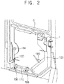
FIG. 2 is a perspective view illustrating an internal structure of the smart door apparatus inFIG. 1 ; -
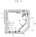
FIG. 3 is a cross-sectional view illustrating a harness of the smart door apparatus inFIG. 2 ; -
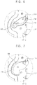
FIGS. 4 and 5 are perspective views illustrating an upper end of the harness of the smart door apparatus inFIG. 1 ; -
FIGS. 6 and 7 are perspective views illustrating a lower end of the harness of the smart door apparatus inFIG. 1 ; -
FIG. 8 is a perspective view illustrating an internal structure of the lower end of the harness inFIG. 7 ; -
FIG. 9 is a perspective view illustrating a closed door inFIG. 1 ; and -
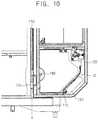
FIG. 10 is a perspective view illustrating an opened door inFIG. 1 . - Various example embodiments will be described more fully hereinafter with reference to the accompanying drawings, in which some example embodiments are shown. The present invention may, however, be embodied in many different forms and should not be construed as limited to the example embodiments set forth herein. Rather, these example embodiments are provided so that this disclosure will be thorough and complete, and will fully convey the scope of the present invention to those skilled in the art. In the drawings, the sizes and relative sizes of layers and regions may be exaggerated for clarity.
- It will be understood that when an element or layer is referred to as being "on," "connected to" or "coupled to" another element or layer, it can be directly on, connected or coupled to the other element or layer or intervening elements or layers may be present. In contrast, when an element is referred to as being "directly on," "directly connected to" or "directly coupled to" another element or layer, there are no intervening elements or layers present. Like numerals refer to like elements throughout. As used herein, the term "and/or" includes any and all combinations of one or more of the associated listed items.
- It will be understood that, although the terms first, second, third etc. may be used herein to describe various elements, components, regions, layers and/or sections, these elements, components, regions, layers and/or sections should not be limited by these terms. These terms are only used to distinguish one element, component, region, layer or section from another region, layer or section. Thus, a first element, component, region, layer or section discussed below could be termed a second element, component, region, layer or section without departing from the teachings of the present invention.
- Spatially relative terms, such as "beneath," "below," "lower," "above," "upper" and the like, may be used herein for ease of description to describe one element or feature's relationship to another element(s) or feature(s) as illustrated in the figures. It will be understood that the spatially relative terms are intended to encompass different orientations of the device in use or operation in addition to the orientation depicted in the figures. For example, if the device in the figures is turned over, elements described as "below" or "beneath" other elements or features would then be oriented "above" the other elements or features. Thus, the exemplary term "below" can encompass both an orientation of above and below. The device may be otherwise oriented (rotated 90 degrees or at other orientations) and the spatially relative descriptors used herein interpreted accordingly.
- The terminology used herein is for the purpose of describing particular example embodiments only and is not intended to be limiting of the present invention. As used herein, the singular forms "a," "an" and "the" are intended to include the plural forms as well, unless the context clearly indicates otherwise. It will be further understood that the terms "comprises" and/or "comprising," when used in this specification, specify the presence of stated features, integers, steps, operations, elements, and/or components, but do not preclude the presence or addition of one or more other features, integers, steps, operations, elements, components, and/or groups thereof.
- Example embodiments are described herein with reference to cross-sectional illustrations that are schematic illustrations of idealized example embodiments (and intermediate structures). As such, variations from the shapes of the illustrations as a result, for example, of manufacturing techniques and/or tolerances, are to be expected. Thus, example embodiments should not be construed as limited to the particular shapes of regions illustrated herein but are to include deviations in shapes that result, for example, from manufacturing. For example, an implanted region illustrated as a rectangle will, typically, have rounded or curved features and/or a gradient of implant concentration at its edges rather than a binary change from implanted to non-implanted region. Likewise, a buried region formed by implantation may result in some implantation in the region between the buried region and the surface through which the implantation takes place. Thus, the regions illustrated in the figures are schematic in nature and their shapes are not intended to illustrate the actual shape of a region of a device and are not intended to limit the scope of the present invention.
- Unless otherwise defined, all terms (including technical and scientific terms) used herein have the same meaning as commonly understood by one of ordinary skill in the art to which this invention belongs. It will be further understood that terms, such as those defined in commonly used dictionaries, should be interpreted as having a meaning that is consistent with their meaning in the context of the relevant art and will not be interpreted in an idealized or overly formal sense unless expressly so defined herein.
- Hereinafter, example embodiments will be explained in detail with reference to the accompanying drawings.
-
FIG. 1 is a perspective view illustrating a cabin of a construction machine with a smart door apparatus in accordance with example embodiments,FIG. 2 is a perspective view illustrating an internal structure of the smart door apparatus inFIG. 1 , andFIG. 3 is a cross-sectional view illustrating a harness of the smart door apparatus inFIG. 2 . - Referring to
FIGS. 1 to 3 , a door D may be installed at a cabin C of a construction machine. The construction machine may not be restricted within a specific construction machine. The door D may be locked to the cabin C by a locking apparatus L. One side surface of the door D may be rotatably connected with the cabin C via a hinge mechanism. Thus, the door D may be rotated with respect to an axial direction X of the hinge mechanism, i.e., a vertical axis. - In example embodiments, the hinge mechanism may include an upper hinge UH configured to rotatably connect an upper end of one side surface of the door D with the cabin C, and a lower hinge LH configured to rotatably connect a lower end of one side surface of the door D with the cabin C. The upper hinge UH may include an upper hinge pin UHP arranged in the axial direction X. The lower hinge LH may include a lower hinge pin LHP arranged in the axial direction X. The upper hinge pin UHP and the lower hinge pin LHP may be positioned on a same line along the axial direction X. Alternatively, the hinge mechanism may include one or at least three hinges.
- The smart door apparatus may operate the locking apparatus L of the door D by signals of a smart key. The smart door apparatus may include an
actuator 120 and aharness 100. Theactuator 120 may be installed at an inner surface of the door D. Theactuator 120 may receive the signals of the smart key to operate the locking apparatus L. - The
harness 100 may be configured to supply electricity to theactuator 120. Theharness 100 may include anouter portion 110 extended from a battery and arranged on an outer surface of the door D, and aninner portion 115 extended from theouter portion 110 into the door D and connected with theactuator 120. - The
outer portion 110 may be extended from an upper surface of the cabin C to a lower end of the door D. In example embodiments, theouter portion 110 may have a linear shape extended in the axial direction X of the hinge mechanism. That is, theouter portion 110 may be positioned on a vertical line substantially the same as the axial direction X of the hinge mechanism. Particularly, theouter portion 110 may be extended between the upper hinge UH and the lower hinge LH in the axial direction X. Thus, theouter portion 110 may be rotated with respect to the axial direction X of the hinge mechanism. As a result, when the door D may be opened, only torsion may be applied to theouter portion 110 regardless of opening angles of the door D. That is, theouter portion 110 may not be bent regardless of the opening angles of the door D. - The
inner portion 115 may be extended from theouter portion 110 through the door D. Theinner portion 115 may be extended along the inner surface of the door D. Theinner portion 115 may be fixed to the inner surface of the door D using a plurality ofclips 180. Theinner portion 115 may be connected to an upper end and a lower end of theactuator 120. -
FIGS. 4 and 5 are perspective views illustrating an upper end of the harness of the smart door apparatus inFIG. 1 . - Referring to
FIGS. 4 and 5 , the smart door apparatus may further include anupper clamp 130 and anupper cover 140. - The
upper clamp 130 may be installed at a portion of the door D adjacent to the upper hinge UH. Theupper clamp 130 may include anupper guide hole 132 and anupper guide groove 134. - The
upper guide hole 132 may be horizontally formed through a portion of theupper clamp 130 right shifted from the axial direction X of the hinge mechanism. An upper end of theouter portion 110 of theharness 100 may be drawn out to the outer surface of the door D through theupper guide hole 132. - The
upper guide groove 134 may be downwardly extended from theupper guide hole 132. Theupper guide groove 134 may have an upper end connected to theupper guide hole 132, and a rounded lower end downwardly extended from the upper end. The lower end of theupper guide groove 134 may be positioned on the axial direction X of the upper hinge UH. That is, the lower end of theupper guide groove 134 may have an axial direction substantially the same as the axial direction X of the upper hinge UH. Thus, the upper end of theouter portion 110 drawn out through theupper guide hole 132 may be guided to be positioned on the axial direction X of the upper hinge UH along theupper guide groove 134. - The
upper cover 140 may be configured to cover theupper clamp 130 and the upper end of theouter portion 110 of theharness 100. Theupper cover 140 may be fixed to theupper clamp 130 and the door D using at least one bolt. -
FIGS. 6 and 7 are perspective views illustrating a lower end of the harness of the smart door apparatus inFIG. 1 . - Referring to
FIGS. 6 and 7 , the smart door apparatus may further include alower clamp 160 and alower cover 170. - The
lower clamp 160 may be installed at a portion of the door D adjacent to the lower hinge LH. Theharness 100 may be divided into theouter portion 110 in the door D and theinner portion 115 outside the door D with respect to thelower clamp 160. Thelower clamp 160 may include alower guide hole 162 and alower guide groove 164. - The
lower guide hole 162 may be horizontally formed through a portion of thelower clamp 160 left shifted from the axial direction X of the hinge mechanism. A lower end of theouter portion 110 of theharness 100 may be drawn out to the inner surface of the door D through thelower guide hole 162. - The
lower guide groove 164 may be upwardly extended from thelower guide hole 162. Thelower guide groove 164 may have a lower end connected to thelower guide hole 162, and a rounded upper end upwardly extended from the lower end. The upper end of thelower guide groove 164 may be positioned on the axial direction X of the lower hinge LH. That is, the upper end of thelower guide groove 164 may have an axial direction substantially the same as the axial direction X of the lower hinge LH. Thus, the lower end of theouter portion 110 extended through the lower end of theupper guide groove 134 to enter into thelower guide groove 164 may be positioned on the axial direction X of the lower hinge LH. - The
lower cover 170 may be configured to cover thelower clamp 160 and the lower end of theouter portion 110 of theharness 100. Thelower cover 170 may be fixed to thelower clamp 170 and the door D using at least one bolt. -
FIG. 8 is a perspective view illustrating an internal structure of the lower end of the harness inFIG. 7 . - Referring to
FIG. 8 , asealant 150 may be configured to fill an inner space of thelower clamp 160. Thesealant 150 may be supplied to the inner space of thelower clamp 160 through a hole of thelower clamp 160. Particularly, thesealant 150 may fill the inner space between thelower clamp 160, thelower cover 170 and the lower end of theouter portion 110 of theharness 100. Theinner portion 115 of theharness 100 extended into the door D through thelower clamp 160 may be fixed by thesealant 150. In contrast, because theouter portion 110 of theharness 100 on the axial direction X of the hinge mechanism may not be fixed, only theouter portion 110 of theharness 100 may be twisted when opening the door D. In example embodiments, thesealant 150 may include silicon. However, thesealant 150 may include other materials as well as the silicon. -
FIG. 9 is a perspective view illustrating a closed door inFIG. 1 , andFIG. 10 is a perspective view illustrating an opened door inFIG. 1 . - Referring to
FIG. 9 , when the door D may be closed, theouter portion 110 of theharness 100 may be positioned on the axial direction X of the hinge mechanism. As shown inFIG. 10 , although the door D may be opened, theouter portion 110 of theharness 100 may also be positioned on the axial direction X of the hinge mechanism. That is, theouter portion 110 of theharness 100 may be always positioned on the axial direction X of the hinge mechanism regardless of the rotation angles of the door D. Therefore, a bending force may not be applied to theouter portion 110 of theharness 100. Only the torsion may be applied to theouter portion 110 of theharness 100 regardless of the rotation angles of the door D. As a result, theouter portion 110 of theharness 100 may not be disconnected to increase the lifespan of theharness 100. - According to example embodiments, the harness may be arranged in the axial direction of the hinge mechanism so that only torsion may be applied to the harness regardless of rotation angles of the door. Thus, the harness may not be bent by a rotation of the door to prevent a disconnection of the harness. As a result, a lifespan of the harness may be increased.
- The foregoing is illustrative of example embodiments and is not to be construed as limiting thereof. Although a few example embodiments have been described, those skilled in the art will readily appreciate that many modifications are possible in the example embodiments without materially departing from the novel teachings and advantages of the present invention. Accordingly, all such modifications are intended to be included within the scope of the present invention as defined in the claims. In the claims, means-plus-function clauses are intended to cover the structures described herein as performing the recited function and not only structural equivalents but also equivalent structures. Therefore, it is to be understood that the foregoing is illustrative of various example embodiments and is not to be construed as limited to the specific example embodiments disclosed, and that modifications to the disclosed example embodiments, as well as other example embodiments, are intended to be included within the scope of the appended claims.
Claims (11)
- A smart door apparatus of a construction machine, the smart door apparatus comprising:an actuator installed at a door, which is rotatably connected with a cabin of the construction machine via a hinge mechanism, to operate a locking apparatus of the door by signals of a smart key; anda harness arranged in an axial direction of the hinge mechanism to supply electricity to the actuator.
- The smart door apparatus of claim 1, wherein the hinge mechanism comprises an upper hinge connected to an upper end of the door and a lower hinge connected to a lower end of the door, and the harness is extended between the upper hinge and the lower hinge along the axial direction.
- The smart door apparatus of claim 2, further comprising:an upper clamp installed at the upper end of the door adjacent to the upper hinge to fix an upper end of the harness; anda lower clamp installed at the lower end of the door adjacent to the lower hinge to fix a lower end of the harness.
- The smart door apparatus of claim 3, wherein the upper clamp comprises:an upper guide hole configured to receive the upper end of the harness; andan upper guide groove extended from the upper guide hole to guide the harness along the axial direction.
- The smart door apparatus of claim 4, wherein the upper guide hole is shifted from the axial direction and a lower end of the upper guide groove is positioned on the axial direction.
- The smart door apparatus of claim 3, wherein the lower clamp comprises:a lower guide hole configured to receive the lower end of the harness; anda lower guide groove extended from the lower guide hole to guide the harness along the axial direction.
- The smart door apparatus of claim 6, wherein the lower guide hole is shifted from the axial direction, and an upper end of the lower guide groove is positioned on the axial direction.
- The smart door apparatus of claim 3, further comprising:an upper cover configured to cover the upper clamp; anda lower cover configured to cover the lower clamp.
- The smart door apparatus of claim 8, further comprising a sealant configured to fill a space between the lower cover, the lower clamp and the lower end of the harness to fix the harness.
- The smart door apparatus of claim 1, wherein the harness is arranged on an outer surface of the door along the axial direction, and the harness enters into the door to be connected to the actuator.
- The smart door apparatus of claim 10, further comprising at least one clip configured to fix the harness in the door to an inner surface of the door.
Applications Claiming Priority (1)
| Application Number | Priority Date | Filing Date | Title |
|---|---|---|---|
| KR1020180134173A KR102657301B1 (en) | 2018-11-05 | 2018-11-05 | Smart door apparatus of a construction machine |
Publications (2)
| Publication Number | Publication Date |
|---|---|
| EP3647125A1 true EP3647125A1 (en) | 2020-05-06 |
| EP3647125B1 EP3647125B1 (en) | 2025-07-02 |
Family
ID=68621112
Family Applications (1)
| Application Number | Title | Priority Date | Filing Date |
|---|---|---|---|
| EP19207067.0A Active EP3647125B1 (en) | 2018-11-05 | 2019-11-05 | Smart door apparatus of a construction machine |
Country Status (4)
| Country | Link |
|---|---|
| US (1) | US11084434B2 (en) |
| EP (1) | EP3647125B1 (en) |
| KR (1) | KR102657301B1 (en) |
| CN (1) | CN111140115A (en) |
Families Citing this family (3)
| Publication number | Priority date | Publication date | Assignee | Title |
|---|---|---|---|---|
| JP6971773B2 (en) * | 2017-10-20 | 2021-11-24 | 株式会社小松製作所 | Work vehicle cab, work vehicle and wheel loader |
| FR3090723B1 (en) * | 2018-12-21 | 2022-08-12 | Safran Electrical & Power | DOOR HINGE FOR ELECTRIC CABINET |
| US12473712B2 (en) * | 2021-03-18 | 2025-11-18 | Hitachi Construction Machinery Co., Ltd. | Construction machine |
Citations (6)
| Publication number | Priority date | Publication date | Assignee | Title |
|---|---|---|---|---|
| GB2274553A (en) * | 1993-01-20 | 1994-07-27 | Sumitomo Wall Systems Ltd | Flexible conduit |
| JPH09243861A (en) * | 1996-03-12 | 1997-09-19 | Yazaki Corp | Connection structure for photoconductor coupling and structure |
| EP1184230A1 (en) * | 2000-09-01 | 2002-03-06 | LEONI Bordnetz-Systeme GmbH & Co KG | Wire harness |
| WO2003029590A1 (en) * | 2001-09-27 | 2003-04-10 | BSH Bosch und Siemens Hausgeräte GmbH | Guide and fixing element for electric cables in the pivoting region of doors |
| WO2009011624A1 (en) * | 2007-07-13 | 2009-01-22 | Volvo Lastvagnar Ab | Electric wire protection arrangement |
| US7943854B1 (en) * | 2008-09-19 | 2011-05-17 | Yazaki North America | Wire twist optimizing grommet |
Family Cites Families (14)
| Publication number | Priority date | Publication date | Assignee | Title |
|---|---|---|---|---|
| BE756106A (en) * | 1969-09-15 | 1971-02-15 | Ford Motor Co | SYSTEM FOR THE PASSAGE OF A HARNESS OF FLAT ELECTRIC WIRES |
| JP2000085492A (en) * | 1998-09-11 | 2000-03-28 | Harness Syst Tech Res Ltd | Power supply for door |
| JP2002249002A (en) * | 2001-02-22 | 2002-09-03 | Yazaki Corp | Door hinge harness |
| DE10259980B3 (en) * | 2002-12-20 | 2004-09-30 | Daimlerchrysler Ag | Motor vehicle, especially small transporter, has cable conduit between body and flap or door with body part fixed to connection opening of vehicle body at connection end |
| US8451087B2 (en) * | 2007-12-25 | 2013-05-28 | Ford Global Technologies, Llc | Passive entry system for automotive vehicle doors |
| DE202010007548U1 (en) * | 2010-05-31 | 2011-10-05 | Brose Fahrzeugteile Gmbh & Co. Kg, Hallstadt | Vehicle door with a arranged on a subframe harness |
| JP5418425B2 (en) * | 2010-07-01 | 2014-02-19 | コベルコ建機株式会社 | Cabin door |
| CN203947964U (en) * | 2014-06-24 | 2014-11-19 | 南京金龙客车制造有限公司 | A kind of automobile-used rear safety door assembly |
| JP6091543B2 (en) * | 2015-04-17 | 2017-03-08 | 本田技研工業株式会社 | Vehicle with rear door structure |
| JP6748409B2 (en) * | 2015-08-24 | 2020-09-02 | 株式会社小松製作所 | Work vehicle |
| US9935413B1 (en) * | 2016-02-18 | 2018-04-03 | Apple Inc. | Hinge pin with electrical connection through a cylindrical pin body |
| CN205905730U (en) * | 2016-05-24 | 2017-01-25 | 上汽通用五菱汽车股份有限公司 | Tail door hinge mounting structure |
| KR20180099362A (en) * | 2017-02-28 | 2018-09-05 | (주)천지테크 | The hinge structure for wiring of construction machines |
| US10399486B2 (en) * | 2017-05-10 | 2019-09-03 | Ford Global Technologies, Llc | Vehicle door removal and storage |
-
2018
- 2018-11-05 KR KR1020180134173A patent/KR102657301B1/en active Active
-
2019
- 2019-11-04 US US16/672,771 patent/US11084434B2/en active Active
- 2019-11-05 EP EP19207067.0A patent/EP3647125B1/en active Active
- 2019-11-05 CN CN201911070856.5A patent/CN111140115A/en active Pending
Patent Citations (6)
| Publication number | Priority date | Publication date | Assignee | Title |
|---|---|---|---|---|
| GB2274553A (en) * | 1993-01-20 | 1994-07-27 | Sumitomo Wall Systems Ltd | Flexible conduit |
| JPH09243861A (en) * | 1996-03-12 | 1997-09-19 | Yazaki Corp | Connection structure for photoconductor coupling and structure |
| EP1184230A1 (en) * | 2000-09-01 | 2002-03-06 | LEONI Bordnetz-Systeme GmbH & Co KG | Wire harness |
| WO2003029590A1 (en) * | 2001-09-27 | 2003-04-10 | BSH Bosch und Siemens Hausgeräte GmbH | Guide and fixing element for electric cables in the pivoting region of doors |
| WO2009011624A1 (en) * | 2007-07-13 | 2009-01-22 | Volvo Lastvagnar Ab | Electric wire protection arrangement |
| US7943854B1 (en) * | 2008-09-19 | 2011-05-17 | Yazaki North America | Wire twist optimizing grommet |
Also Published As
| Publication number | Publication date |
|---|---|
| KR20200051176A (en) | 2020-05-13 |
| CN111140115A (en) | 2020-05-12 |
| US11084434B2 (en) | 2021-08-10 |
| KR102657301B1 (en) | 2024-04-16 |
| EP3647125B1 (en) | 2025-07-02 |
| US20200141168A1 (en) | 2020-05-07 |
Similar Documents
| Publication | Publication Date | Title |
|---|---|---|
| US11084434B2 (en) | Smart door apparatus of a construction machine | |
| US6305129B1 (en) | Door trimming panel having a window-lift mechanism | |
| US9825443B2 (en) | Power transfer unit | |
| US11479113B2 (en) | Fuel door opener assembly | |
| US20040107533A1 (en) | Waterproof Grommet | |
| US11220850B2 (en) | Automotive latch with pulley for flexible cable routing | |
| CN102587722A (en) | Position controlled cable guide clip | |
| US20140252780A1 (en) | Door lock mortise | |
| DE112012003093T5 (en) | Electrical connector | |
| CN105164354A (en) | Handle device for vehicle | |
| US20090000202A1 (en) | Window Lift System and Method for Fitting a Window Pane | |
| CN105317295A (en) | Cylinder lock device | |
| US20140041899A1 (en) | Harness covers for vehicle doors | |
| US20130255411A1 (en) | Tensioning assembly for cable drive | |
| US20080295285A1 (en) | Hinge pin for enclosure | |
| CN101103163A (en) | Vehicle door module and method for connecting an operating device and a handle for a switching mechanism in a vehicle door | |
| CN106289737B (en) | The durability test device and its method of vehicle body shutter member | |
| CN102287076A (en) | Clip assembly for vehicle door latch rod | |
| JP7203251B2 (en) | Assembly and method for moving the cover | |
| CN203475990U (en) | Internal door anti-theft lock | |
| US11170916B2 (en) | Cover | |
| CN117803269A (en) | Door hinge assembly and door-in-door box | |
| CN220488333U (en) | Locking valve | |
| CN103891057A (en) | Lockout device | |
| CN108826639B (en) | Air deflector structure and air conditioner with same |
Legal Events
| Date | Code | Title | Description |
|---|---|---|---|
| PUAI | Public reference made under article 153(3) epc to a published international application that has entered the european phase |
Free format text: ORIGINAL CODE: 0009012 |
|
| STAA | Information on the status of an ep patent application or granted ep patent |
Free format text: STATUS: REQUEST FOR EXAMINATION WAS MADE |
|
| 17P | Request for examination filed |
Effective date: 20191105 |
|
| AK | Designated contracting states |
Kind code of ref document: A1 Designated state(s): AL AT BE BG CH CY CZ DE DK EE ES FI FR GB GR HR HU IE IS IT LI LT LU LV MC MK MT NL NO PL PT RO RS SE SI SK SM TR |
|
| AX | Request for extension of the european patent |
Extension state: BA ME |
|
| RBV | Designated contracting states (corrected) |
Designated state(s): AL AT BE BG CH CY CZ DE DK EE ES FI FR GB GR HR HU IE IS IT LI LT LU LV MC MK MT NL NO PL PT RO RS SE SI SK SM TR |
|
| RAP3 | Party data changed (applicant data changed or rights of an application transferred) |
Owner name: HYUNDAI DOOSAN INFRACORE CO., LTD. |
|
| STAA | Information on the status of an ep patent application or granted ep patent |
Free format text: STATUS: EXAMINATION IS IN PROGRESS |
|
| 17Q | First examination report despatched |
Effective date: 20220720 |
|
| RAP3 | Party data changed (applicant data changed or rights of an application transferred) |
Owner name: HD HYUNDAI INFRACORE CO., LTD. |
|
| GRAP | Despatch of communication of intention to grant a patent |
Free format text: ORIGINAL CODE: EPIDOSNIGR1 |
|
| STAA | Information on the status of an ep patent application or granted ep patent |
Free format text: STATUS: GRANT OF PATENT IS INTENDED |
|
| INTG | Intention to grant announced |
Effective date: 20250326 |
|
| GRAS | Grant fee paid |
Free format text: ORIGINAL CODE: EPIDOSNIGR3 |
|
| GRAA | (expected) grant |
Free format text: ORIGINAL CODE: 0009210 |
|
| STAA | Information on the status of an ep patent application or granted ep patent |
Free format text: STATUS: THE PATENT HAS BEEN GRANTED |
|
| AK | Designated contracting states |
Kind code of ref document: B1 Designated state(s): AL AT BE BG CH CY CZ DE DK EE ES FI FR GB GR HR HU IE IS IT LI LT LU LV MC MK MT NL NO PL PT RO RS SE SI SK SM TR |
|
| REG | Reference to a national code |
Ref country code: GB Ref legal event code: FG4D |
|
| REG | Reference to a national code |
Ref country code: CH Ref legal event code: EP |
|
| REG | Reference to a national code |
Ref country code: DE Ref legal event code: R096 Ref document number: 602019071877 Country of ref document: DE |
|
| REG | Reference to a national code |
Ref country code: IE Ref legal event code: FG4D |
|
| PGFP | Annual fee paid to national office [announced via postgrant information from national office to epo] |
Ref country code: FR Payment date: 20250930 Year of fee payment: 7 |
|
| REG | Reference to a national code |
Ref country code: NL Ref legal event code: MP Effective date: 20250702 |
|
| PG25 | Lapsed in a contracting state [announced via postgrant information from national office to epo] |
Ref country code: PT Free format text: LAPSE BECAUSE OF FAILURE TO SUBMIT A TRANSLATION OF THE DESCRIPTION OR TO PAY THE FEE WITHIN THE PRESCRIBED TIME-LIMIT Effective date: 20251103 |
|
| PG25 | Lapsed in a contracting state [announced via postgrant information from national office to epo] |
Ref country code: NL Free format text: LAPSE BECAUSE OF FAILURE TO SUBMIT A TRANSLATION OF THE DESCRIPTION OR TO PAY THE FEE WITHIN THE PRESCRIBED TIME-LIMIT Effective date: 20250702 |
|
| REG | Reference to a national code |
Ref country code: AT Ref legal event code: MK05 Ref document number: 1808903 Country of ref document: AT Kind code of ref document: T Effective date: 20250702 |
|
| PG25 | Lapsed in a contracting state [announced via postgrant information from national office to epo] |
Ref country code: IS Free format text: LAPSE BECAUSE OF FAILURE TO SUBMIT A TRANSLATION OF THE DESCRIPTION OR TO PAY THE FEE WITHIN THE PRESCRIBED TIME-LIMIT Effective date: 20251102 |
|
| PGFP | Annual fee paid to national office [announced via postgrant information from national office to epo] |
Ref country code: DE Payment date: 20250930 Year of fee payment: 7 |
|
| PGFP | Annual fee paid to national office [announced via postgrant information from national office to epo] |
Ref country code: GB Payment date: 20251001 Year of fee payment: 7 |
|
| PG25 | Lapsed in a contracting state [announced via postgrant information from national office to epo] |
Ref country code: NO Free format text: LAPSE BECAUSE OF FAILURE TO SUBMIT A TRANSLATION OF THE DESCRIPTION OR TO PAY THE FEE WITHIN THE PRESCRIBED TIME-LIMIT Effective date: 20251002 |
|
| REG | Reference to a national code |
Ref country code: LT Ref legal event code: MG9D |
|
| PG25 | Lapsed in a contracting state [announced via postgrant information from national office to epo] |
Ref country code: AT Free format text: LAPSE BECAUSE OF FAILURE TO SUBMIT A TRANSLATION OF THE DESCRIPTION OR TO PAY THE FEE WITHIN THE PRESCRIBED TIME-LIMIT Effective date: 20250702 |
|
| PG25 | Lapsed in a contracting state [announced via postgrant information from national office to epo] |
Ref country code: FI Free format text: LAPSE BECAUSE OF FAILURE TO SUBMIT A TRANSLATION OF THE DESCRIPTION OR TO PAY THE FEE WITHIN THE PRESCRIBED TIME-LIMIT Effective date: 20250702 |
|
| PGFP | Annual fee paid to national office [announced via postgrant information from national office to epo] |
Ref country code: IT Payment date: 20251022 Year of fee payment: 7 |
|
| PG25 | Lapsed in a contracting state [announced via postgrant information from national office to epo] |
Ref country code: HR Free format text: LAPSE BECAUSE OF FAILURE TO SUBMIT A TRANSLATION OF THE DESCRIPTION OR TO PAY THE FEE WITHIN THE PRESCRIBED TIME-LIMIT Effective date: 20250702 |
|
| PG25 | Lapsed in a contracting state [announced via postgrant information from national office to epo] |
Ref country code: GR Free format text: LAPSE BECAUSE OF FAILURE TO SUBMIT A TRANSLATION OF THE DESCRIPTION OR TO PAY THE FEE WITHIN THE PRESCRIBED TIME-LIMIT Effective date: 20251003 |
|
| PG25 | Lapsed in a contracting state [announced via postgrant information from national office to epo] |
Ref country code: SE Free format text: LAPSE BECAUSE OF FAILURE TO SUBMIT A TRANSLATION OF THE DESCRIPTION OR TO PAY THE FEE WITHIN THE PRESCRIBED TIME-LIMIT Effective date: 20250702 Ref country code: CZ Free format text: LAPSE BECAUSE OF FAILURE TO SUBMIT A TRANSLATION OF THE DESCRIPTION OR TO PAY THE FEE WITHIN THE PRESCRIBED TIME-LIMIT Effective date: 20250702 |
|
| PG25 | Lapsed in a contracting state [announced via postgrant information from national office to epo] |
Ref country code: LV Free format text: LAPSE BECAUSE OF FAILURE TO SUBMIT A TRANSLATION OF THE DESCRIPTION OR TO PAY THE FEE WITHIN THE PRESCRIBED TIME-LIMIT Effective date: 20250702 |
|
| PG25 | Lapsed in a contracting state [announced via postgrant information from national office to epo] |
Ref country code: PL Free format text: LAPSE BECAUSE OF FAILURE TO SUBMIT A TRANSLATION OF THE DESCRIPTION OR TO PAY THE FEE WITHIN THE PRESCRIBED TIME-LIMIT Effective date: 20250702 Ref country code: BG Free format text: LAPSE BECAUSE OF FAILURE TO SUBMIT A TRANSLATION OF THE DESCRIPTION OR TO PAY THE FEE WITHIN THE PRESCRIBED TIME-LIMIT Effective date: 20250702 |
|
| PG25 | Lapsed in a contracting state [announced via postgrant information from national office to epo] |
Ref country code: RS Free format text: LAPSE BECAUSE OF FAILURE TO SUBMIT A TRANSLATION OF THE DESCRIPTION OR TO PAY THE FEE WITHIN THE PRESCRIBED TIME-LIMIT Effective date: 20251002 |
|
| PG25 | Lapsed in a contracting state [announced via postgrant information from national office to epo] |
Ref country code: ES Free format text: LAPSE BECAUSE OF FAILURE TO SUBMIT A TRANSLATION OF THE DESCRIPTION OR TO PAY THE FEE WITHIN THE PRESCRIBED TIME-LIMIT Effective date: 20250702 |
|
| PG25 | Lapsed in a contracting state [announced via postgrant information from national office to epo] |
Ref country code: RO Free format text: LAPSE BECAUSE OF FAILURE TO SUBMIT A TRANSLATION OF THE DESCRIPTION OR TO PAY THE FEE WITHIN THE PRESCRIBED TIME-LIMIT Effective date: 20250702 |
|
| PG25 | Lapsed in a contracting state [announced via postgrant information from national office to epo] |
Ref country code: SM Free format text: LAPSE BECAUSE OF FAILURE TO SUBMIT A TRANSLATION OF THE DESCRIPTION OR TO PAY THE FEE WITHIN THE PRESCRIBED TIME-LIMIT Effective date: 20250702 |
|
| PG25 | Lapsed in a contracting state [announced via postgrant information from national office to epo] |
Ref country code: DK Free format text: LAPSE BECAUSE OF FAILURE TO SUBMIT A TRANSLATION OF THE DESCRIPTION OR TO PAY THE FEE WITHIN THE PRESCRIBED TIME-LIMIT Effective date: 20250702 |
|
| PG25 | Lapsed in a contracting state [announced via postgrant information from national office to epo] |
Ref country code: SK Free format text: LAPSE BECAUSE OF FAILURE TO SUBMIT A TRANSLATION OF THE DESCRIPTION OR TO PAY THE FEE WITHIN THE PRESCRIBED TIME-LIMIT Effective date: 20250702 Ref country code: EE Free format text: LAPSE BECAUSE OF FAILURE TO SUBMIT A TRANSLATION OF THE DESCRIPTION OR TO PAY THE FEE WITHIN THE PRESCRIBED TIME-LIMIT Effective date: 20250702 |
|
| PLBE | No opposition filed within time limit |
Free format text: ORIGINAL CODE: 0009261 |
|
| STAA | Information on the status of an ep patent application or granted ep patent |
Free format text: STATUS: NO OPPOSITION FILED WITHIN TIME LIMIT |