EP3647027A1 - Method of manufacturing a panel of a wind turbine nacelle - Google Patents
Method of manufacturing a panel of a wind turbine nacelle Download PDFInfo
- Publication number
- EP3647027A1 EP3647027A1 EP19197669.5A EP19197669A EP3647027A1 EP 3647027 A1 EP3647027 A1 EP 3647027A1 EP 19197669 A EP19197669 A EP 19197669A EP 3647027 A1 EP3647027 A1 EP 3647027A1
- Authority
- EP
- European Patent Office
- Prior art keywords
- panel
- mould
- divider
- nacelle
- spacer
- Prior art date
- Legal status (The legal status is an assumption and is not a legal conclusion. Google has not performed a legal analysis and makes no representation as to the accuracy of the status listed.)
- Granted
Links
Images



Classifications
-
- B—PERFORMING OPERATIONS; TRANSPORTING
- B29—WORKING OF PLASTICS; WORKING OF SUBSTANCES IN A PLASTIC STATE IN GENERAL
- B29C—SHAPING OR JOINING OF PLASTICS; SHAPING OF MATERIAL IN A PLASTIC STATE, NOT OTHERWISE PROVIDED FOR; AFTER-TREATMENT OF THE SHAPED PRODUCTS, e.g. REPAIRING
- B29C70/00—Shaping composites, i.e. plastics material comprising reinforcements, fillers or preformed parts, e.g. inserts
- B29C70/04—Shaping composites, i.e. plastics material comprising reinforcements, fillers or preformed parts, e.g. inserts comprising reinforcements only, e.g. self-reinforcing plastics
- B29C70/28—Shaping operations therefor
- B29C70/30—Shaping by lay-up, i.e. applying fibres, tape or broadsheet on a mould, former or core; Shaping by spray-up, i.e. spraying of fibres on a mould, former or core
-
- F—MECHANICAL ENGINEERING; LIGHTING; HEATING; WEAPONS; BLASTING
- F03—MACHINES OR ENGINES FOR LIQUIDS; WIND, SPRING, OR WEIGHT MOTORS; PRODUCING MECHANICAL POWER OR A REACTIVE PROPULSIVE THRUST, NOT OTHERWISE PROVIDED FOR
- F03D—WIND MOTORS
- F03D1/00—Wind motors with rotation axis substantially parallel to the air flow entering the rotor
-
- B—PERFORMING OPERATIONS; TRANSPORTING
- B29—WORKING OF PLASTICS; WORKING OF SUBSTANCES IN A PLASTIC STATE IN GENERAL
- B29C—SHAPING OR JOINING OF PLASTICS; SHAPING OF MATERIAL IN A PLASTIC STATE, NOT OTHERWISE PROVIDED FOR; AFTER-TREATMENT OF THE SHAPED PRODUCTS, e.g. REPAIRING
- B29C33/00—Moulds or cores; Details thereof or accessories therefor
- B29C33/42—Moulds or cores; Details thereof or accessories therefor characterised by the shape of the moulding surface, e.g. ribs or grooves
-
- B—PERFORMING OPERATIONS; TRANSPORTING
- B29—WORKING OF PLASTICS; WORKING OF SUBSTANCES IN A PLASTIC STATE IN GENERAL
- B29C—SHAPING OR JOINING OF PLASTICS; SHAPING OF MATERIAL IN A PLASTIC STATE, NOT OTHERWISE PROVIDED FOR; AFTER-TREATMENT OF THE SHAPED PRODUCTS, e.g. REPAIRING
- B29C70/00—Shaping composites, i.e. plastics material comprising reinforcements, fillers or preformed parts, e.g. inserts
- B29C70/04—Shaping composites, i.e. plastics material comprising reinforcements, fillers or preformed parts, e.g. inserts comprising reinforcements only, e.g. self-reinforcing plastics
- B29C70/28—Shaping operations therefor
- B29C70/54—Component parts, details or accessories; Auxiliary operations, e.g. feeding or storage of prepregs or SMC after impregnation or during ageing
-
- B—PERFORMING OPERATIONS; TRANSPORTING
- B29—WORKING OF PLASTICS; WORKING OF SUBSTANCES IN A PLASTIC STATE IN GENERAL
- B29C—SHAPING OR JOINING OF PLASTICS; SHAPING OF MATERIAL IN A PLASTIC STATE, NOT OTHERWISE PROVIDED FOR; AFTER-TREATMENT OF THE SHAPED PRODUCTS, e.g. REPAIRING
- B29C70/00—Shaping composites, i.e. plastics material comprising reinforcements, fillers or preformed parts, e.g. inserts
- B29C70/04—Shaping composites, i.e. plastics material comprising reinforcements, fillers or preformed parts, e.g. inserts comprising reinforcements only, e.g. self-reinforcing plastics
- B29C70/28—Shaping operations therefor
- B29C70/54—Component parts, details or accessories; Auxiliary operations, e.g. feeding or storage of prepregs or SMC after impregnation or during ageing
- B29C70/541—Positioning reinforcements in a mould, e.g. using clamping means for the reinforcement
-
- B—PERFORMING OPERATIONS; TRANSPORTING
- B29—WORKING OF PLASTICS; WORKING OF SUBSTANCES IN A PLASTIC STATE IN GENERAL
- B29D—PRODUCING PARTICULAR ARTICLES FROM PLASTICS OR FROM SUBSTANCES IN A PLASTIC STATE
- B29D99/00—Subject matter not provided for in other groups of this subclass
- B29D99/006—Producing casings, e.g. accumulator cases
-
- F—MECHANICAL ENGINEERING; LIGHTING; HEATING; WEAPONS; BLASTING
- F03—MACHINES OR ENGINES FOR LIQUIDS; WIND, SPRING, OR WEIGHT MOTORS; PRODUCING MECHANICAL POWER OR A REACTIVE PROPULSIVE THRUST, NOT OTHERWISE PROVIDED FOR
- F03D—WIND MOTORS
- F03D13/00—Assembly, mounting or commissioning of wind motors; Arrangements specially adapted for transporting wind motor components
- F03D13/10—Assembly of wind motors; Arrangements for erecting wind motors
-
- F—MECHANICAL ENGINEERING; LIGHTING; HEATING; WEAPONS; BLASTING
- F03—MACHINES OR ENGINES FOR LIQUIDS; WIND, SPRING, OR WEIGHT MOTORS; PRODUCING MECHANICAL POWER OR A REACTIVE PROPULSIVE THRUST, NOT OTHERWISE PROVIDED FOR
- F03D—WIND MOTORS
- F03D80/00—Details, components or accessories not provided for in groups F03D1/00 - F03D17/00
-
- B—PERFORMING OPERATIONS; TRANSPORTING
- B29—WORKING OF PLASTICS; WORKING OF SUBSTANCES IN A PLASTIC STATE IN GENERAL
- B29C—SHAPING OR JOINING OF PLASTICS; SHAPING OF MATERIAL IN A PLASTIC STATE, NOT OTHERWISE PROVIDED FOR; AFTER-TREATMENT OF THE SHAPED PRODUCTS, e.g. REPAIRING
- B29C2793/00—Shaping techniques involving a cutting or machining operation
- B29C2793/0072—Shaping techniques involving a cutting or machining operation combined with rearranging and joining the cut parts
-
- B—PERFORMING OPERATIONS; TRANSPORTING
- B29—WORKING OF PLASTICS; WORKING OF SUBSTANCES IN A PLASTIC STATE IN GENERAL
- B29L—INDEXING SCHEME ASSOCIATED WITH SUBCLASS B29C, RELATING TO PARTICULAR ARTICLES
- B29L2031/00—Other particular articles
- B29L2031/748—Machines or parts thereof not otherwise provided for
- B29L2031/7504—Turbines
-
- F—MECHANICAL ENGINEERING; LIGHTING; HEATING; WEAPONS; BLASTING
- F03—MACHINES OR ENGINES FOR LIQUIDS; WIND, SPRING, OR WEIGHT MOTORS; PRODUCING MECHANICAL POWER OR A REACTIVE PROPULSIVE THRUST, NOT OTHERWISE PROVIDED FOR
- F03D—WIND MOTORS
- F03D13/00—Assembly, mounting or commissioning of wind motors; Arrangements specially adapted for transporting wind motor components
- F03D13/40—Arrangements or methods specially adapted for transporting wind motor components
-
- F—MECHANICAL ENGINEERING; LIGHTING; HEATING; WEAPONS; BLASTING
- F05—INDEXING SCHEMES RELATING TO ENGINES OR PUMPS IN VARIOUS SUBCLASSES OF CLASSES F01-F04
- F05B—INDEXING SCHEME RELATING TO WIND, SPRING, WEIGHT, INERTIA OR LIKE MOTORS, TO MACHINES OR ENGINES FOR LIQUIDS COVERED BY SUBCLASSES F03B, F03D AND F03G
- F05B2230/00—Manufacture
-
- F—MECHANICAL ENGINEERING; LIGHTING; HEATING; WEAPONS; BLASTING
- F05—INDEXING SCHEMES RELATING TO ENGINES OR PUMPS IN VARIOUS SUBCLASSES OF CLASSES F01-F04
- F05B—INDEXING SCHEME RELATING TO WIND, SPRING, WEIGHT, INERTIA OR LIKE MOTORS, TO MACHINES OR ENGINES FOR LIQUIDS COVERED BY SUBCLASSES F03B, F03D AND F03G
- F05B2230/00—Manufacture
- F05B2230/60—Assembly methods
-
- F—MECHANICAL ENGINEERING; LIGHTING; HEATING; WEAPONS; BLASTING
- F05—INDEXING SCHEMES RELATING TO ENGINES OR PUMPS IN VARIOUS SUBCLASSES OF CLASSES F01-F04
- F05B—INDEXING SCHEME RELATING TO WIND, SPRING, WEIGHT, INERTIA OR LIKE MOTORS, TO MACHINES OR ENGINES FOR LIQUIDS COVERED BY SUBCLASSES F03B, F03D AND F03G
- F05B2240/00—Components
- F05B2240/10—Stators
- F05B2240/14—Casings, housings, nacelles, gondels or the like, protecting or supporting assemblies there within
-
- F—MECHANICAL ENGINEERING; LIGHTING; HEATING; WEAPONS; BLASTING
- F05—INDEXING SCHEMES RELATING TO ENGINES OR PUMPS IN VARIOUS SUBCLASSES OF CLASSES F01-F04
- F05B—INDEXING SCHEME RELATING TO WIND, SPRING, WEIGHT, INERTIA OR LIKE MOTORS, TO MACHINES OR ENGINES FOR LIQUIDS COVERED BY SUBCLASSES F03B, F03D AND F03G
- F05B2280/00—Materials; Properties thereof
- F05B2280/60—Properties or characteristics given to material by treatment or manufacturing
- F05B2280/6003—Composites; e.g. fibre-reinforced
-
- Y—GENERAL TAGGING OF NEW TECHNOLOGICAL DEVELOPMENTS; GENERAL TAGGING OF CROSS-SECTIONAL TECHNOLOGIES SPANNING OVER SEVERAL SECTIONS OF THE IPC; TECHNICAL SUBJECTS COVERED BY FORMER USPC CROSS-REFERENCE ART COLLECTIONS [XRACs] AND DIGESTS
- Y02—TECHNOLOGIES OR APPLICATIONS FOR MITIGATION OR ADAPTATION AGAINST CLIMATE CHANGE
- Y02E—REDUCTION OF GREENHOUSE GAS [GHG] EMISSIONS, RELATED TO ENERGY GENERATION, TRANSMISSION OR DISTRIBUTION
- Y02E10/00—Energy generation through renewable energy sources
- Y02E10/70—Wind energy
- Y02E10/72—Wind turbines with rotation axis in wind direction
-
- Y—GENERAL TAGGING OF NEW TECHNOLOGICAL DEVELOPMENTS; GENERAL TAGGING OF CROSS-SECTIONAL TECHNOLOGIES SPANNING OVER SEVERAL SECTIONS OF THE IPC; TECHNICAL SUBJECTS COVERED BY FORMER USPC CROSS-REFERENCE ART COLLECTIONS [XRACs] AND DIGESTS
- Y02—TECHNOLOGIES OR APPLICATIONS FOR MITIGATION OR ADAPTATION AGAINST CLIMATE CHANGE
- Y02P—CLIMATE CHANGE MITIGATION TECHNOLOGIES IN THE PRODUCTION OR PROCESSING OF GOODS
- Y02P70/00—Climate change mitigation technologies in the production process for final industrial or consumer products
- Y02P70/50—Manufacturing or production processes characterised by the final manufactured product
Definitions
- the invention describes a method of claim 1 of manufacturing a panel of a wind turbine nacelle; a method of constructing a wind turbine nacelle; and a wind turbine.
- the shipping container most commonly used for transport in Europe and China has the ISO 668 1AA designation, i.e. a length of 40', a width of 8', and a height of 8'6".
- a container is usually simply referred to as a "40-foot standard container”.
- This container size can be used to transport a variety of different payloads. However, any object whose length exceeds 40' (12.19 m) cannot be transported using such a shipping container.
- the enclosing nacelle may need to have a length in excess of 40', so that transport of nacelle parts to the installation site may pose significant logistical problems that are costly to resolve.
- One approach is to manufacture the nacelle using only panels that comply with the 40' constraint, and to assemble the panels on site. For a long nacelle in excess of 40', each panel section is moulded using a dedicated mould, which adds significantly to the overall manufacturing costs.
- the method of manufacturing a panel of a wind turbine nacelle comprises the steps of providing a mould for the panel; arranging at least one divider in the mould to spatially divide the mould interior into at least a first mould region and a second mould region; arranging composite material of the mould; curing the composite material; and separating the panel into at least a first panel portion and a second panel portion along a line defined by a divider.
- the panel can later be assembled from the panel portions.
- the shape and dimensions of the mould correspond to the shape and dimensions of a complete panel, i.e. the mould is a negative of the complete panel.
- a panel may be assumed to comprise a number of sides or faces, for example a panel may comprise part of the nacelle floor and also part of a nacelle side wall. It shall be assumed that the panel dimensions exceed the size constraints of a 40-foot shipping container.
- One or more dividers are arranged in the mould so that the dimensions of each resulting mould region (and corresponding panel portion) lie within payload size constraints of a 40-foot shipping container.
- a single divider can be used to define two panel portions for any panel that can be constructed from two portions, each of which fits into a 40-foot shipping container.
- any number of dividers can be used to obtain three or more panel portions of a multi-part panel. Since a divider is arranged in the mould to spatially divide the mould interior into adjacent mould regions, it may be assumed to protrude into the mould interior, i.e. to occupy space which would otherwise (in the absence of the divider) be filled by composite material.
- a divider is used to divide the mould into regions, i.e. to divide a panel into portions, it may be referred to in the following as a mould divider, a panel divider, or a panel separator.
- the step of arranging composite material in the mould may be understood as the usual layup technique in which layers of composite material such as fibreglass mats, carbon-fibre reinforced plastic, rovings etc., are arranged in the mould. Generally, this is preceded by applying a release agent to all mould surfaces and also to all relevant surfaces of a panel divider. It is also usual to apply a suitable gelcoat layer that will form the outer surface of the cured part. After curing, the panel is demoulded, and the divider is removed from between the adjacent panel portions.
- An advantage of the inventive method is that it is not necessary to design individual smaller panels that fit into a 40-foot shipping container, and it is not necessary to provide dedicated moulds for such panels. Instead, it is possible to use the mould of a large panel (i.e. any panel whose length exceeds the length of a 40-foot shipping container) as a basis, from which smaller panel portions are formed by judicious placement of one or more dividers in the mould. Costs can be kept to a favourable minimum by using an already existing mould for such a large panel, for example a mould used to manufacture a 13 m side, floor or roof panel of a nacelle.
- the method of constructing a wind turbine nacelle comprises the steps of providing a set of nacelle panels at an installation site, whereby at least one panel is a multi-part panel manufactured using the inventive panel manufacturing method as described above; connecting panel portions of a multi-part panel; and assembling all panels of the set to obtain the complete nacelle. Since the panel portions of any panel of the nacelle can be manufactured with relatively little effort to fit inside a 40-foot shipping container, the nacelle manufacturing and transport costs can be kept to an advantageously low level.
- the wind turbine comprises a nacelle constructed in the manner described above.
- the costs associated with construction of the nacelle can be reduced as described above, so that the cost of installing the wind turbine is also correspondingly low.
- a 40-foot shipping container is sometimes also referred to as a "maritime container” or “standard container”, so that these terms may be used interchangeably.
- the nacelle is for a wind turbine comprising a drivetrain with a gearbox, power converter modules etc., since this type of wind turbine requires a relatively long nacelle to accommodate the various components.
- a divider occupies space which would otherwise be filled by composite material.
- a divider can comprise a band of suitable material such as metal, plastic etc. that is at least as thick as the composite material, i.e. at least as thick as the panel wall thickness.
- composite material can be laid up in the mould on either side of the divider.
- the panel portions can simply be lifted out of the mould.
- the composite material is arranged in the mould to completely cover the divider. After curing, adjacent panel portions are separated by cutting along a line defined by the corresponding divider.
- a divider comprises a T-shaped profile, for example a T-bar having dimensions of a standard EN-10055 profile, or two back-to-back standard EN-10056 angle profiles. While these standards apply to steel parts, the divider used in the inventive method can be made of any suitable material and is preferably shaped according to such a standard.
- the resulting cast panel will exhibit one or more corresponding raised ridges.
- the individual panel portions can be separated easily by cutting through the raised ridge formed by a divider.
- the height of the cutting line can be chosen to leave a flange along the edge of each panel portion, and the corresponding flanges can be connected together in a suitable manner when the nacelle is being assembled.
- a nacelle panel does not always comprise a simple flat or planar shape. Instead, a nacelle panel (and its corresponding mould) may include a step or other contour. Therefore, in a preferred embodiment of the invention, a panel divider is shaped to follow such a step or a contour in the mould.
- the step of providing the mould comprises a step of forming inserts to receive fasteners for securing a panel divider to a surface of the mould.
- a row of holes can be formed in the mould, for example along a line corresponding to the centre line of a divider, so that the divider can be screwed to the mould (preferably using screws inserted from the outside of the mould).
- the panels of a nacelle are generally manufactured to a high degree of accuracy, so that when the panels are assembled, the nacelle specifications are met.
- panel portions of a panel are manufactured using a mould whose dimensions correspond to the complete panel.
- the step of connecting adjacent panel portions comprises arranging a spacer between the panel portions, wherein the thickness of the spacer corresponds to the thickness of the divider that was used to delineate those panel portions.
- Such a spacer can be an injection-moulded or 3D-printed part, for example a 3D-printed part made from a suitable thermoplastic such as acrylonitrile styrene acrylate (ASA).
- ASA acrylonitrile styrene acrylate
- such a spacer comprises a spacer body and a sealant layer such as a strip of sealing tape applied to the spacer body and arranged to lie against a corresponding surface of a panel portion.
- the thickness of a spacer does not exceed the thickness of the corresponding divider.
- the spacer body preferably exhibits a high degree of stiffness.
- a spacer instead of providing a single spacer with the same length as the joint or seam, a spacer preferably comprises a plurality of shorter spacer elements.
- the spacer elements are formed so that each spacer element is shaped to engage with an adjacent spacer element.
- a connection between adjacent spacer elements can be achieved by a suitable form-fit shape of the corresponding edges of adjacent spacer elements.
- a spacer preferably comprises a number of bushings, wherein a bushing is arranged to accommodate a fastener used to connect two panel portions.
- the spacer can be formed so that the outer end of a bushing extends beyond the level of the spacer body by an amount corresponding to the thickness of a sealant layer.
- spacer and/or spacer elements can be made of any suitable material and can be made using any suitable technique.
- spacer elements can be made as injection-moulded parts.
- spacer elements can be 3D-printed parts made from a suitable thermoplastic such as acrylonitrile styrene acrylate (ASA).
- ASA acrylonitrile styrene acrylate
- Fig 1 shows a one-piece panel 1 of a nacelle.
- the dimensions of the nacelle are such that the length L1 of the one-piece panel 1 exceeds the length of a standard shipping container used to transport wind turbine components to an installation site.
- a standard shipping container 9 is shown in Fig 9 .
- the standard container or 40' container has a length L9 of 40', a width W9 of 8' and a height H9 of 8'6".
- long panels must be assembled from smaller parts.
- the prior art approach is to construct smaller moulds for the smaller parts. The added cost of these steps can be considerable, especially when the panel 1 includes irregular shapes such as the contour 10 shown here.
- a mould 3 which been constructed for the manufacture of a one-piece panel 1 as shown in Fig 1 is used.
- a suitable division line D is chosen, as indicated in Fig 1 , and through-holes are formed in the mould 3 along that line.
- a divider 4 is secured to the mould 3 to delineate or define a first mould region 3A and a second mould region 3B as shown in Fig 2 .
- the divider 4 is formed as a profile with a T-shaped cross-section.
- the divider 4 can be a 3D-printed or injection-moulded part, formed to follow any contour of the mould 3, as shown in the enlarged portion of the diagram.
- the position of the divider 4, which will result in a ridge or seam in the nacelle interior, is preferably planned under consideration of the intended positions of components within the nacelle.
- the diagram only shows a single divider, but it shall be understood that any number of dividers can be arranged in the mould to obtain a corresponding number of panel portions.
- the surfaces of the mould 3 and the divider 4 are coated in the usual manner with a release coat. Gelcoat layers can also be applied as appropriate.
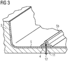
- Fig 3 shows a further stage in the manufacturing method. After arranging layers of composite material 5 such as fibreglass mats, rovings etc. in the mould, thereby also completely covering the divider 4, the composite material is cured. A ridge 50 has been formed, following the shape of the divider 4. This diagram also shows a through-hole 11 formed in the mould 3 along the division line, and a fastener 12 used to secure the divider 4 to the mould 3.
- composite material 5 such as fibreglass mats, rovings etc.
- Fig 4 illustrates a subsequent stage in the manufacturing method.
- the cured panel 1' is shown, with an exemplary cutting line X along the top of the ridge 50.
- the tip of the ridge 50 shown in Fig 3 is removed, effectively separating a first panel portion 1A from a second panel portion 1B.
- the combined lengths (L1A + LIB) of the panel portions 1A, 1B will be less than the length L1 of the desired panel, owing to the thickness 40 of the divider 4.
- Fig 5 shows a stage in the assembly of the panel portions 1A, 1B of Fig 4 .
- a spacer 6 is shown.
- the spacer 6 will lie between opposing faces 13A, 13B of the panel portions 1A, 1B.
- This spacer 6 will compensate for the thickness T4 of the divider 4 and will be used to join the panel portions 1A, 1B.
- Fig 6 shows an exemplary spacer 6.
- the spacer 6 comprises a series of interconnecting spacer elements 60.
- Each spacer element 60 or spacer body 60 has complementary form-fit shapes 60A, 60B at its outer ends so that each spacer element 60 can engage with two further identical spacer elements 60.
- the diagram also shows two bushings 61 extending through a spacer body 60. Each bushing 61 can accommodate a fastener when the panel portions are being joined.
- the diagram also shows strips of sealant tape 62.
- Fig 7 illustrates a connection between panel portions 1A, 1B, showing a spacer body 6 between opposing faces 13A, 13B of the panel portions 1A, 1B.
- the diagram shows that a bushing 61 extends outward on each side of the spacer body 60 so that the end-to-end length of a bushing 61 corresponds to the thickness T4 of the divider 4.
- the sealant tape 61 can be slightly thicker than the protruding end of a bushing 61, so that the sealant tape can be compressed to a certain extent when fasteners 15 are used to join the panel portions 1A, 1B on either side of the spacer 6.
- Fig 8 shows an alternative realization, in which sealant material 61 is applied over the side surfaces of a spacer body 60.
- Fig 10 shows a wind turbine 8 comprising a nacelle 80 assembled from at least two side panels, a roof panel, a floor panel, and a rear panel.
- the overall length of the nacelle 80 corresponds to the length L1 of the longest panel, for example a side panel 1.
- the panel 1 is preferably made as a multi-part panel, for example a two-part panel as shown here, with panel portions 1A, 1B manufactured and assembled as explained above. Because the panel portions are made from the same mould that would be used to manufacture a one-piece panel shown in Fig 1 , the dimensions of the multi-part panel are essentially the same as the dimensions of the one-piece panel. This simplifies installation of the wind turbine.
- a divider can be bolted onto the mould by fasteners extending through the body of the divider and into the body of the mould.
- a divider can be secured to the mould using any suitable adhesive.
- two panel portions can be joined or connected using any suitable parts, whereby the dimensions of the parts and the materials from which they are made may be chosen under consideration of factors such as material hardness, compressibility, durability etc.
Landscapes
- Engineering & Computer Science (AREA)
- Mechanical Engineering (AREA)
- Chemical & Material Sciences (AREA)
- Composite Materials (AREA)
- Life Sciences & Earth Sciences (AREA)
- Sustainable Development (AREA)
- Sustainable Energy (AREA)
- Combustion & Propulsion (AREA)
- General Engineering & Computer Science (AREA)
- Wind Motors (AREA)
Abstract
Description
- The invention describes a method of
claim 1 of manufacturing a panel of a wind turbine nacelle; a method of constructing a wind turbine nacelle; and a wind turbine. - The shipping container most commonly used for transport in Europe and China has the ISO 668 1AA designation, i.e. a length of 40', a width of 8', and a height of 8'6". Such a container is usually simply referred to as a "40-foot standard container". This container size can be used to transport a variety of different payloads. However, any object whose length exceeds 40' (12.19 m) cannot be transported using such a shipping container.
- For a large wind turbine with a generator comprising a gearbox, the enclosing nacelle may need to have a length in excess of 40', so that transport of nacelle parts to the installation site may pose significant logistical problems that are costly to resolve. One approach is to manufacture the nacelle using only panels that comply with the 40' constraint, and to assemble the panels on site. For a long nacelle in excess of 40', each panel section is moulded using a dedicated mould, which adds significantly to the overall manufacturing costs.
- It is therefore an object of the invention to provide an alternative way of constructing a nacelle from parts that can be transported using a standard shipping container.
- This object is achieved by the method of
claim 1 of manufacturing a panel of a wind turbine nacelle; and by the method of claim 8 of constructing a wind turbine nacelle. - According to the invention, the method of manufacturing a panel of a wind turbine nacelle comprises the steps of providing a mould for the panel; arranging at least one divider in the mould to spatially divide the mould interior into at least a first mould region and a second mould region; arranging composite material of the mould; curing the composite material; and separating the panel into at least a first panel portion and a second panel portion along a line defined by a divider. The panel can later be assembled from the panel portions.
- In the context of
claim 1, it shall be understood that the shape and dimensions of the mould correspond to the shape and dimensions of a complete panel, i.e. the mould is a negative of the complete panel. Such a panel may be assumed to comprise a number of sides or faces, for example a panel may comprise part of the nacelle floor and also part of a nacelle side wall. It shall be assumed that the panel dimensions exceed the size constraints of a 40-foot shipping container. One or more dividers are arranged in the mould so that the dimensions of each resulting mould region (and corresponding panel portion) lie within payload size constraints of a 40-foot shipping container. - A single divider can be used to define two panel portions for any panel that can be constructed from two portions, each of which fits into a 40-foot shipping container. Of course, any number of dividers can be used to obtain three or more panel portions of a multi-part panel. Since a divider is arranged in the mould to spatially divide the mould interior into adjacent mould regions, it may be assumed to protrude into the mould interior, i.e. to occupy space which would otherwise (in the absence of the divider) be filled by composite material.
- Since a divider is used to divide the mould into regions, i.e. to divide a panel into portions, it may be referred to in the following as a mould divider, a panel divider, or a panel separator. The step of arranging composite material in the mould may be understood as the usual layup technique in which layers of composite material such as fibreglass mats, carbon-fibre reinforced plastic, rovings etc., are arranged in the mould. Generally, this is preceded by applying a release agent to all mould surfaces and also to all relevant surfaces of a panel divider. It is also usual to apply a suitable gelcoat layer that will form the outer surface of the cured part. After curing, the panel is demoulded, and the divider is removed from between the adjacent panel portions.
- An advantage of the inventive method is that it is not necessary to design individual smaller panels that fit into a 40-foot shipping container, and it is not necessary to provide dedicated moulds for such panels. Instead, it is possible to use the mould of a large panel (i.e. any panel whose length exceeds the length of a 40-foot shipping container) as a basis, from which smaller panel portions are formed by judicious placement of one or more dividers in the mould. Costs can be kept to a favourable minimum by using an already existing mould for such a large panel, for example a mould used to manufacture a 13 m side, floor or roof panel of a nacelle.
- According to the invention, the method of constructing a wind turbine nacelle comprises the steps of providing a set of nacelle panels at an installation site, whereby at least one panel is a multi-part panel manufactured using the inventive panel manufacturing method as described above; connecting panel portions of a multi-part panel; and assembling all panels of the set to obtain the complete nacelle. Since the panel portions of any panel of the nacelle can be manufactured with relatively little effort to fit inside a 40-foot shipping container, the nacelle manufacturing and transport costs can be kept to an advantageously low level.
- According to the invention, the wind turbine comprises a nacelle constructed in the manner described above. The costs associated with construction of the nacelle can be reduced as described above, so that the cost of installing the wind turbine is also correspondingly low.
- Particularly advantageous embodiments and features of the invention are given by the dependent claims, as revealed in the following description. Features of different claim categories may be combined as appropriate to give further embodiments not described herein.
- A 40-foot shipping container is sometimes also referred to as a "maritime container" or "standard container", so that these terms may be used interchangeably.
- In the following, without restricting the invention in any way, it may be assumed that the nacelle is for a wind turbine comprising a drivetrain with a gearbox, power converter modules etc., since this type of wind turbine requires a relatively long nacelle to accommodate the various components.
- After curing the panel, it is separated into two or more panel portions. As explained above, a divider occupies space which would otherwise be filled by composite material. In a very simple approach, a divider can comprise a band of suitable material such as metal, plastic etc. that is at least as thick as the composite material, i.e. at least as thick as the panel wall thickness. In such an approach, composite material can be laid up in the mould on either side of the divider. After curing, the panel portions can simply be lifted out of the mould. However, such an approach may involve more effort in the lay-up process, since the edges of each portion must terminate cleanly along the divider. Therefore, in a preferred embodiment of the invention, the composite material is arranged in the mould to completely cover the divider. After curing, adjacent panel portions are separated by cutting along a line defined by the corresponding divider.
- Adjacent panel portions must be joined together when the nacelle is being assembled. A joint between adjacent panel portions must be structurally strong as well as water-tight. Preferably therefore, the divider is not simply used to delineate adjacent panel portions, and is instead shaped to also define a connection interface between the panel portions. In a preferred embodiment of the invention, a divider comprises a T-shaped profile, for example a T-bar having dimensions of a standard EN-10055 profile, or two back-to-back standard EN-10056 angle profiles. While these standards apply to steel parts, the divider used in the inventive method can be made of any suitable material and is preferably shaped according to such a standard. With one or more such T-shaped dividers arranged in the mould, the resulting cast panel will exhibit one or more corresponding raised ridges. The individual panel portions can be separated easily by cutting through the raised ridge formed by a divider. The height of the cutting line can be chosen to leave a flange along the edge of each panel portion, and the corresponding flanges can be connected together in a suitable manner when the nacelle is being assembled.
- A nacelle panel does not always comprise a simple flat or planar shape. Instead, a nacelle panel (and its corresponding mould) may include a step or other contour. Therefore, in a preferred embodiment of the invention, a panel divider is shaped to follow such a step or a contour in the mould.
- During layup, it is necessary to ensure that the divider does not move from its original position, so that the panel portions will have the intended dimensions. Therefore, in a preferred embodiment of the invention, the step of providing the mould comprises a step of forming inserts to receive fasteners for securing a panel divider to a surface of the mould. A row of holes can be formed in the mould, for example along a line corresponding to the centre line of a divider, so that the divider can be screwed to the mould (preferably using screws inserted from the outside of the mould).
- Once the panel portions of a nacelle have been manufactured as described above, these can be loaded into a standard container and transported to an installation site.
- The panels of a nacelle are generally manufactured to a high degree of accuracy, so that when the panels are assembled, the nacelle specifications are met. Using the inventive method, panel portions of a panel are manufactured using a mould whose dimensions correspond to the complete panel. However, because one or more dividers are used to define the panel portions, the combined length of the panel portions will be less than the specified length of a panel. The difference will correspond essentially to the total width of the dividers used in manufacturing the panel portions. Therefore, in a preferred embodiment of the invention, the step of connecting adjacent panel portions comprises arranging a spacer between the panel portions, wherein the thickness of the spacer corresponds to the thickness of the divider that was used to delineate those panel portions. Such a spacer can be an injection-moulded or 3D-printed part, for example a 3D-printed part made from a suitable thermoplastic such as acrylonitrile styrene acrylate (ASA). Preferably, such a spacer comprises a spacer body and a sealant layer such as a strip of sealing tape applied to the spacer body and arranged to lie against a corresponding surface of a panel portion. Preferably, the thickness of a spacer does not exceed the thickness of the corresponding divider. The spacer body preferably exhibits a high degree of stiffness.
- As mentioned above, two adjacent panel portions can have a low flange along their edges, and these can be joined together when the nacelle is being assembled. Such a joint or "seam" can be relatively long. Therefore, instead of providing a single spacer with the same length as the joint or seam, a spacer preferably comprises a plurality of shorter spacer elements. In a particularly preferred embodiment of the invention, the spacer elements are formed so that each spacer element is shaped to engage with an adjacent spacer element. A connection between adjacent spacer elements can be achieved by a suitable form-fit shape of the corresponding edges of adjacent spacer elements. Such an approach allows a favourably quick assembly of adjacent panel portions.
- To ensure a robust connection between panel portions, these are preferably bolted or screwed together. To this end, a spacer preferably comprises a number of bushings, wherein a bushing is arranged to accommodate a fastener used to connect two panel portions. The spacer can be formed so that the outer end of a bushing extends beyond the level of the spacer body by an amount corresponding to the thickness of a sealant layer.
- A spacer and/or spacer elements can be made of any suitable material and can be made using any suitable technique. For example, spacer elements can be made as injection-moulded parts. Equally, spacer elements can be 3D-printed parts made from a suitable thermoplastic such as acrylonitrile styrene acrylate (ASA).
- Other objects and features of the present invention will become apparent from the following detailed descriptions considered in conjunction with the accompanying drawings. It is to be understood, however, that the drawings are designed solely for the purposes of illustration and not as a definition of the limits of the invention.
-
Fig 1 shows a one-piece panel of a nacelle; -
Figs 2 - 4 show stages in an embodiment of the inventive manufacturing method; -
Fig 5 shows a stage in the assembly of panel portions obtained using the inventive manufacturing method; -
Fig 6 shows an exemplary spacer used to connect panel portions obtained using the inventive manufacturing method; -
Fig 7 shows a connection between panel portions obtained using the inventive manufacturing method; -
Fig 8 shows an alternative spacer used to connect panel portions obtained using the inventive manufacturing method; -
Fig 9 shows a standard shipping container; -
Fig 10 shows an embodiment of the inventive wind turbine. - In the diagrams, like numbers refer to like objects throughout. Objects in the diagrams are not necessarily drawn to scale.
-
Fig 1 shows a one-piece panel 1 of a nacelle. The dimensions of the nacelle are such that the length L1 of the one-piece panel 1 exceeds the length of a standard shipping container used to transport wind turbine components to an installation site. Such an exemplary shipping container 9 is shown inFig 9 . The standard container or 40' container has a length L9 of 40', a width W9 of 8' and a height H9 of 8'6". To be able to transport nacelle panels with such a container, long panels must be assembled from smaller parts. The prior art approach is to construct smaller moulds for the smaller parts. The added cost of these steps can be considerable, especially when thepanel 1 includes irregular shapes such as thecontour 10 shown here. - In the manufacturing method according to the invention, a different approach is taken. Here, a
mould 3 which been constructed for the manufacture of a one-piece panel 1 as shown inFig 1 is used. A suitable division line D is chosen, as indicated inFig 1 , and through-holes are formed in themould 3 along that line. By means of fasteners inserted through these holes, adivider 4 is secured to themould 3 to delineate or define afirst mould region 3A and asecond mould region 3B as shown inFig 2 . In this exemplary embodiment, thedivider 4 is formed as a profile with a T-shaped cross-section. Thedivider 4 can be a 3D-printed or injection-moulded part, formed to follow any contour of themould 3, as shown in the enlarged portion of the diagram. The position of thedivider 4, which will result in a ridge or seam in the nacelle interior, is preferably planned under consideration of the intended positions of components within the nacelle. The diagram only shows a single divider, but it shall be understood that any number of dividers can be arranged in the mould to obtain a corresponding number of panel portions. The surfaces of themould 3 and thedivider 4 are coated in the usual manner with a release coat. Gelcoat layers can also be applied as appropriate. -
Fig 3 shows a further stage in the manufacturing method. After arranging layers ofcomposite material 5 such as fibreglass mats, rovings etc. in the mould, thereby also completely covering thedivider 4, the composite material is cured. A ridge 50 has been formed, following the shape of thedivider 4. This diagram also shows a through-hole 11 formed in themould 3 along the division line, and afastener 12 used to secure thedivider 4 to themould 3. -
Fig 4 illustrates a subsequent stage in the manufacturing method. Here, the cured panel 1' is shown, with an exemplary cutting line X along the top of the ridge 50. Using a suitable blade or saw, the tip of the ridge 50 shown inFig 3 is removed, effectively separating afirst panel portion 1A from asecond panel portion 1B. The combined lengths (L1A + LIB) of thepanel portions divider 4. -
Fig 5 shows a stage in the assembly of thepanel portions Fig 4 . Here, aspacer 6 is shown. Thespacer 6 will lie between opposingfaces panel portions - This
spacer 6 will compensate for the thickness T4 of thedivider 4 and will be used to join thepanel portions -
Fig 6 shows anexemplary spacer 6. Here, thespacer 6 comprises a series of interconnectingspacer elements 60. Eachspacer element 60 orspacer body 60 has complementary form-fit shapes spacer element 60 can engage with two furtheridentical spacer elements 60. The diagram also shows twobushings 61 extending through aspacer body 60. Eachbushing 61 can accommodate a fastener when the panel portions are being joined. The diagram also shows strips ofsealant tape 62. -
Fig 7 illustrates a connection betweenpanel portions spacer body 6 between opposingfaces panel portions bushing 61 extends outward on each side of thespacer body 60 so that the end-to-end length of abushing 61 corresponds to the thickness T4 of thedivider 4. Thesealant tape 61 can be slightly thicker than the protruding end of abushing 61, so that the sealant tape can be compressed to a certain extent whenfasteners 15 are used to join thepanel portions spacer 6. -
Fig 8 shows an alternative realization, in whichsealant material 61 is applied over the side surfaces of aspacer body 60. -
Fig 10 shows a wind turbine 8 comprising anacelle 80 assembled from at least two side panels, a roof panel, a floor panel, and a rear panel. The overall length of thenacelle 80 corresponds to the length L1 of the longest panel, for example aside panel 1. When this length L1 exceeds the length L9 of a standard shipping container 9 as shown inFig 9 , thepanel 1 is preferably made as a multi-part panel, for example a two-part panel as shown here, withpanel portions Fig 1 , the dimensions of the multi-part panel are essentially the same as the dimensions of the one-piece panel. This simplifies installation of the wind turbine. - Although the present invention has been disclosed in the form of preferred embodiments and variations thereon, it will be understood that numerous additional modifications and variations could be made thereto without departing from the scope of the invention. For example, a divider can be bolted onto the mould by fasteners extending through the body of the divider and into the body of the mould. Alternatively, a divider can be secured to the mould using any suitable adhesive. Instead of the spacer described above, two panel portions can be joined or connected using any suitable parts, whereby the dimensions of the parts and the materials from which they are made may be chosen under consideration of factors such as material hardness, compressibility, durability etc.
- For the sake of clarity, it is to be understood that the use of "a" or "an" throughout this application does not exclude a plurality, and "comprising" does not exclude other steps or elements.
Claims (15)
- A method of manufacturing a panel (1) of a wind turbine nacelle (80), which method comprises the steps of- providing a mould (3) for the panel (1);- arranging at least one divider (4) in the mould (3) to spatially divide the mould (3) into at least a first mould region (3A) and a second mould region (3B);- arranging composite material (5) in the mould (3);- curing the composite material (5); and- separating the cured panel (1') into at least a first panel portion (1A) and a second panel portion (1B) along a line (D) defined by a divider (4).
- A method according to claim 1, wherein a divider (4) is arranged in the mould (3) so that the dimensions of the mould regions (3A, 3B) lie within size constraints of a 40-foot shipping container (9).
- A method according to claim 1 or claim 2, wherein a divider (4) is shaped to form a connection interface between a first panel portion (1A) and a second panel portion (1B).
- A method according to any of the preceding claims, wherein a divider (4) comprises a T-shaped profile.
- A method according to any of the preceding claims, wherein the step of arranging composite material (5) in the mould (3) includes covering a divider (4).
- A method according to any of the preceding claims, wherein the divider (4) is shaped to follow a contour (10) in the mould (3).
- A method according to any of the preceding claims, wherein the step of providing the mould (3) comprises a step of forming inserts (11) to receive fasteners (12) for securing a divider (4) to a surface of the mould (3).
- A method of constructing a wind turbine nacelle (80), which method comprises the steps of- providing a set of nacelle panels at an installation site, whereby at least one panel is provided in the form of panel portions (1A, 1B) of a multi-part panel (1) manufactured using the method according to any of claims 1 to 7;- connecting panel portions (1A, 1B) of a multi-part panel (1); and- assembling all panels of the nacelle panel set.
- A method according to claim 8, wherein the step of providing the nacelle panel set comprises transporting the panel portions (1A, 1B) of a multi-part panel (1) to the installation site by means of a 40-foot shipping container (9).
- A method according to claim 8 or claim 9, wherein the step of connecting portions (1A, 1B) of a multi-part panel (1) comprises arranging a spacer (6) between opposing faces (13A, 13B) of the panel portions (1A, 1B).
- A method according to claim 10, wherein a spacer (6) comprises a sealant layer (62) arranged to lie against a corresponding surface (13A, 13B) of a panel portion (1A, 1B).
- A method according to claim 10 or claim 11, wherein the thickness of a spacer (6) does not exceed the thickness (T4) of the corresponding divider (4).
- A method according to any of claims 10 to 12, wherein a spacer (6) comprises a plurality of spacer elements (60), wherein a spacer element (60) is shaped to engage with an adjacent spacer element (60).
- A method according to any of claims 10 to 13, wherein a spacer (6) comprises a number of bushings (61), and wherein a bushing (61) is arranged to accommodate a fastener (15) extending through opposing faces (13A, 13B) of the first and second panel portions (1A 1B).
- A wind turbine (8) comprising a nacelle (80) constructed according to any of claims 8 to 14.
Applications Claiming Priority (1)
| Application Number | Priority Date | Filing Date | Title |
|---|---|---|---|
| ES201800245A ES2757536B2 (en) | 2018-10-29 | 2018-10-29 | Manufacturing method of a panel of a wind turbine nacelle |
Publications (2)
| Publication Number | Publication Date |
|---|---|
| EP3647027A1 true EP3647027A1 (en) | 2020-05-06 |
| EP3647027B1 EP3647027B1 (en) | 2026-04-08 |
Family
ID=67988890
Family Applications (1)
| Application Number | Title | Priority Date | Filing Date |
|---|---|---|---|
| EP19197669.5A Active EP3647027B1 (en) | 2018-10-29 | 2019-09-17 | Method of manufacturing a panel of a wind turbine nacelle |
Country Status (5)
| Country | Link |
|---|---|
| US (1) | US11293405B2 (en) |
| EP (1) | EP3647027B1 (en) |
| CN (1) | CN111098518A (en) |
| BR (1) | BR102019022228B1 (en) |
| ES (1) | ES2757536B2 (en) |
Citations (3)
| Publication number | Priority date | Publication date | Assignee | Title |
|---|---|---|---|---|
| US20110233819A1 (en) * | 2010-03-25 | 2011-09-29 | Repower Systems Ag | Device and partial mold for the production of rotor blades for wind power plants and methods for the production |
| US20150308404A1 (en) * | 2012-12-18 | 2015-10-29 | Lm Wp Patent Holding A/S | A wind turbine blade comprising an aerodynamic blade shell with recess and pre-manufactured spar cap |
| US20170363071A1 (en) * | 2015-01-22 | 2017-12-21 | Vestas Wind Systems A/S | Wind turbine nacelle |
Family Cites Families (14)
| Publication number | Priority date | Publication date | Assignee | Title |
|---|---|---|---|---|
| CA1071367A (en) * | 1972-05-22 | 1980-02-12 | John L. Bourdo | Fabrication of structural members |
| US5297772A (en) * | 1992-02-24 | 1994-03-29 | Stefanick William F | Improvements on molds for making composite blocks |
| CN1459367A (en) | 2002-05-24 | 2003-12-03 | 南京航空航天大学 | Isolation layer made of injection moulding resin mixed composite material and its manufacturing method |
| EP2063119A3 (en) | 2007-11-21 | 2014-04-30 | Siemens Aktiengesellschaft | Module of a nacelle of a wind turbine and method of assembly |
| US20100232977A1 (en) * | 2009-03-13 | 2010-09-16 | Vestas Wind Systems A/S | Height Adjustable Wind Turbine Nacelle |
| KR101030521B1 (en) * | 2010-06-28 | 2011-04-26 | 주식회사 비엔에스산업 | Manufacturing method of nacelle for wind power generator with prefabricated structure |
| DE102010025546A1 (en) * | 2010-06-29 | 2011-12-29 | Suzlon Energy Gmbh | Nacelle paneling |
| DK2418072T3 (en) | 2010-08-13 | 2018-11-19 | Lm Wind Power Int Tech Ii Aps | A method of making an elongate composite body |
| ITTV20110067A1 (en) | 2011-05-19 | 2012-11-20 | Angelo Basso | METHOD FOR THE PRODUCTION OF LASTRIFORMS ELEMENTS IN POLYMERIC MATERIAL AND ITS EQUIPMENT |
| FR2989310B1 (en) | 2012-04-11 | 2014-04-04 | Aircelle Sa | METHOD FOR MANUFACTURING SANDWICH PANEL COMPOSITE WITH ALVEOLAR SOUL |
| DE102012014738A1 (en) * | 2012-07-26 | 2014-01-30 | Ferdinand Rothkopf jun. | Method for producing a component made of fiber-reinforced plastic |
| EP3034284A1 (en) * | 2014-12-16 | 2016-06-22 | Airbus Operations S.L. | Method and system for manufacturing of a moulded CFRP part |
| CN105729733B (en) | 2016-04-27 | 2018-08-14 | 宁波市益普乐模塑有限公司 | The molding die of SMC products |
| DK179720B1 (en) * | 2017-08-16 | 2019-04-11 | Jupiter Bach A/S | A method of manufacturing composite laminate panel sub-elements for a modular assembly structure, a method of assembling the sub-elements, and a structure assembled of the panel sub-elements |
-
2018
- 2018-10-29 ES ES201800245A patent/ES2757536B2/en not_active Expired - Fee Related
-
2019
- 2019-09-17 EP EP19197669.5A patent/EP3647027B1/en active Active
- 2019-10-17 US US16/655,623 patent/US11293405B2/en active Active
- 2019-10-23 BR BR102019022228-0A patent/BR102019022228B1/en active IP Right Grant
- 2019-10-29 CN CN201911036826.2A patent/CN111098518A/en active Pending
Patent Citations (3)
| Publication number | Priority date | Publication date | Assignee | Title |
|---|---|---|---|---|
| US20110233819A1 (en) * | 2010-03-25 | 2011-09-29 | Repower Systems Ag | Device and partial mold for the production of rotor blades for wind power plants and methods for the production |
| US20150308404A1 (en) * | 2012-12-18 | 2015-10-29 | Lm Wp Patent Holding A/S | A wind turbine blade comprising an aerodynamic blade shell with recess and pre-manufactured spar cap |
| US20170363071A1 (en) * | 2015-01-22 | 2017-12-21 | Vestas Wind Systems A/S | Wind turbine nacelle |
Also Published As
| Publication number | Publication date |
|---|---|
| EP3647027B1 (en) | 2026-04-08 |
| US11293405B2 (en) | 2022-04-05 |
| US20200132050A1 (en) | 2020-04-30 |
| BR102019022228B1 (en) | 2023-12-05 |
| ES2757536A1 (en) | 2020-04-29 |
| BR102019022228A2 (en) | 2020-05-26 |
| CN111098518A (en) | 2020-05-05 |
| ES2757536B2 (en) | 2020-12-01 |
Similar Documents
| Publication | Publication Date | Title |
|---|---|---|
| US11041477B2 (en) | Reinforcing structure for a wind turbine blade | |
| CN110757855B (en) | Scalable modular component architecture and scalable nacelle cover or spinner cover kit | |
| EP3308013B1 (en) | Modular wind turbine blades | |
| EP2153979B1 (en) | Multispar torsion box made from composite material | |
| US6245275B1 (en) | Method for fabricating composite structures | |
| US8382440B2 (en) | Efficient wind turbine blades, wind turbine blade structures, and associated systems and methods of manufacture, assembly and use | |
| CN103732381A (en) | Method and device for transporting, placing and compacting composite stiffeners | |
| US9701391B2 (en) | Aircraft structure comprising a skin panel | |
| EP0217315A2 (en) | Wing box cover panel and method of making same | |
| EP0967147A2 (en) | Composite material wing structure | |
| US12215667B2 (en) | Longitudinal edge extension | |
| CA2938798C (en) | Method for manufacturing a rotor blade of a wind power plant, rotor blade and wind power plant | |
| EP2951085A2 (en) | Structural assembly joint | |
| CN111186591A (en) | Method for manufacturing a multi-ribbed wing box made of composite material from integrally reinforced panels | |
| KR20050088396A (en) | Large composite structures and a process for fabricating large composite structures | |
| EP3647027B1 (en) | Method of manufacturing a panel of a wind turbine nacelle | |
| EP3628583A1 (en) | Thermoplastic multi-grid overmolded/co-consolidated aircraft fuselage structure | |
| CN111186592A (en) | Method for manufacturing a multi-ribbed wing box of composite material with an integrally reinforced plate and communicating chambers | |
| EP4497582A1 (en) | Method for manufacturing a wind turbine blade and wind turbine blade |
Legal Events
| Date | Code | Title | Description |
|---|---|---|---|
| PUAI | Public reference made under article 153(3) epc to a published international application that has entered the european phase |
Free format text: ORIGINAL CODE: 0009012 |
|
| STAA | Information on the status of an ep patent application or granted ep patent |
Free format text: STATUS: THE APPLICATION HAS BEEN PUBLISHED |
|
| AK | Designated contracting states |
Kind code of ref document: A1 Designated state(s): AL AT BE BG CH CY CZ DE DK EE ES FI FR GB GR HR HU IE IS IT LI LT LU LV MC MK MT NL NO PL PT RO RS SE SI SK SM TR |
|
| STAA | Information on the status of an ep patent application or granted ep patent |
Free format text: STATUS: REQUEST FOR EXAMINATION WAS MADE |
|
| 17P | Request for examination filed |
Effective date: 20201103 |
|
| RBV | Designated contracting states (corrected) |
Designated state(s): AL AT BE BG CH CY CZ DE DK EE ES FI FR GB GR HR HU IE IS IT LI LT LU LV MC MK MT NL NO PL PT RO RS SE SI SK SM TR |
|
| STAA | Information on the status of an ep patent application or granted ep patent |
Free format text: STATUS: EXAMINATION IS IN PROGRESS |
|
| 17Q | First examination report despatched |
Effective date: 20220705 |
|
| REG | Reference to a national code |
Ref legal event code: R079 Free format text: PREVIOUS MAIN CLASS: B29C0070300000 Ref country code: DE Ref document number: 602019083317 Country of ref document: DE Ipc: F03D0013100000 |
|
| GRAP | Despatch of communication of intention to grant a patent |
Free format text: ORIGINAL CODE: EPIDOSNIGR1 |
|
| STAA | Information on the status of an ep patent application or granted ep patent |
Free format text: STATUS: GRANT OF PATENT IS INTENDED |
|
| RIC1 | Information provided on ipc code assigned before grant |
Ipc: F03D 13/10 20160101AFI20251113BHEP Ipc: B29C 33/42 20060101ALI20251113BHEP Ipc: B29C 70/30 20060101ALI20251113BHEP Ipc: B29D 99/00 20100101ALI20251113BHEP |
|
| INTG | Intention to grant announced |
Effective date: 20251125 |
|
| GRAS | Grant fee paid |
Free format text: ORIGINAL CODE: EPIDOSNIGR3 |
|
| GRAA | (expected) grant |
Free format text: ORIGINAL CODE: 0009210 |
|
| STAA | Information on the status of an ep patent application or granted ep patent |
Free format text: STATUS: THE PATENT HAS BEEN GRANTED |
|
| AK | Designated contracting states |
Kind code of ref document: B1 Designated state(s): AL AT BE BG CH CY CZ DE DK EE ES FI FR GB GR HR HU IE IS IT LI LT LU LV MC MK MT NL NO PL PT RO RS SE SI SK SM TR |
|
| REG | Reference to a national code |
Ref country code: CH Ref legal event code: F10 Free format text: ST27 STATUS EVENT CODE: U-0-0-F10-F00 (AS PROVIDED BY THE NATIONAL OFFICE) Effective date: 20260408 Ref country code: GB Ref legal event code: FG4D |
|
| REG | Reference to a national code |
Ref country code: DE Ref legal event code: R096 Ref document number: 602019083317 Country of ref document: DE |