EP3646988A1 - Support, machine and process for surface finishing - Google Patents
Support, machine and process for surface finishing Download PDFInfo
- Publication number
- EP3646988A1 EP3646988A1 EP19205910.3A EP19205910A EP3646988A1 EP 3646988 A1 EP3646988 A1 EP 3646988A1 EP 19205910 A EP19205910 A EP 19205910A EP 3646988 A1 EP3646988 A1 EP 3646988A1
- Authority
- EP
- European Patent Office
- Prior art keywords
- support
- vibrating
- previous
- piece
- axis
- Prior art date
- Legal status (The legal status is an assumption and is not a legal conclusion. Google has not performed a legal analysis and makes no representation as to the accuracy of the status listed.)
- Granted
Links
Images






Classifications
-
- B—PERFORMING OPERATIONS; TRANSPORTING
- B24—GRINDING; POLISHING
- B24B—MACHINES, DEVICES, OR PROCESSES FOR GRINDING OR POLISHING; DRESSING OR CONDITIONING OF ABRADING SURFACES; FEEDING OF GRINDING, POLISHING, OR LAPPING AGENTS
- B24B31/00—Machines or devices designed for polishing or abrading surfaces on work by means of tumbling apparatus or other apparatus in which the work and/or the abrasive material is loose; Accessories therefor
- B24B31/003—Machines or devices designed for polishing or abrading surfaces on work by means of tumbling apparatus or other apparatus in which the work and/or the abrasive material is loose; Accessories therefor whereby the workpieces are mounted on a holder and are immersed in the abrasive material
-
- B—PERFORMING OPERATIONS; TRANSPORTING
- B24—GRINDING; POLISHING
- B24B—MACHINES, DEVICES, OR PROCESSES FOR GRINDING OR POLISHING; DRESSING OR CONDITIONING OF ABRADING SURFACES; FEEDING OF GRINDING, POLISHING, OR LAPPING AGENTS
- B24B31/00—Machines or devices designed for polishing or abrading surfaces on work by means of tumbling apparatus or other apparatus in which the work and/or the abrasive material is loose; Accessories therefor
- B24B31/06—Machines or devices designed for polishing or abrading surfaces on work by means of tumbling apparatus or other apparatus in which the work and/or the abrasive material is loose; Accessories therefor involving oscillating or vibrating containers
- B24B31/064—Machines or devices designed for polishing or abrading surfaces on work by means of tumbling apparatus or other apparatus in which the work and/or the abrasive material is loose; Accessories therefor involving oscillating or vibrating containers the workpieces being fitted on a support
-
- B—PERFORMING OPERATIONS; TRANSPORTING
- B24—GRINDING; POLISHING
- B24B—MACHINES, DEVICES, OR PROCESSES FOR GRINDING OR POLISHING; DRESSING OR CONDITIONING OF ABRADING SURFACES; FEEDING OF GRINDING, POLISHING, OR LAPPING AGENTS
- B24B31/00—Machines or devices designed for polishing or abrading surfaces on work by means of tumbling apparatus or other apparatus in which the work and/or the abrasive material is loose; Accessories therefor
- B24B31/12—Accessories; Protective equipment or safety devices; Installations for exhaustion of dust or for sound absorption specially adapted for machines covered by group B24B31/00
-
- B—PERFORMING OPERATIONS; TRANSPORTING
- B24—GRINDING; POLISHING
- B24B—MACHINES, DEVICES, OR PROCESSES FOR GRINDING OR POLISHING; DRESSING OR CONDITIONING OF ABRADING SURFACES; FEEDING OF GRINDING, POLISHING, OR LAPPING AGENTS
- B24B41/00—Component parts such as frames, beds, carriages, headstocks
- B24B41/06—Work supports, e.g. adjustable steadies
- B24B41/061—Work supports, e.g. adjustable steadies axially supporting turning workpieces, e.g. magnetically, pneumatically
Definitions
- the present description relates to a support for surface finishing, in particular a support that can be used to support a piece during a surface finishing thereof.
- the present description also relates to a machine and a process which can use such a support.
- Known machines for surface finishing comprise a vibrating tank that can contain pieces and abrasive elements suitable to treat the outer surface of these pieces when the tank is vibrated.
- the pieces and the abrasive elements are free to move in the vibrating tank, since they are not fastened to any support.
- Such known machines cannot treat the inner surface of the pieces homogeneously, especially if these comprise ducts of different shape and/or section, long and/or curved, such as those made with 3D printers, so that the final results of the surface finishing are unsatisfactory.
- the object of the present description is therefore to provide a machine which is free from these drawbacks. Said object is achieved with a particular support, a machine and a process, whose main features are specified in the attached claims.
- the machine is able to perform a suitable finishing not only of the outer surface of the pieces but also of their inner surfaces, in particular long and/or curved ducts.
- the support is preferably fixed to the vibrating tank of the machine to vibrate with it and induce further vibrations to the piece, in particular vibrations close to the resonant frequency of the support, so as to optimize the effect of the vibrations for the surface finishing of the piece.
- the support preferably comprises at least one joint, a counterweight, a vibrator and/or an actuator to further improve the speed and/or quality of the surface finishing of the piece fixed to the support.
- the fastening device and/or the joint of the support can be fixed in a removable manner respectively to two ends of the elastic member, preferably a bar made of spring steel having a round or square section with a given length, so as to adapt the support to the particular piece to be treated.
- the machine preferably comprises means for rotating the support around an axis, in particular a substantially horizontal axis, so as to be able to arrange the piece both inside the mass of the abrasive elements and outside this mass, so as to adjust the processing times of the surface finishing, even for different pieces arranged in the same vibrating tank.
- the support and/or the machine preferably exploit the movement of the abrasive elements to rotate the pieces around one or more axes in the vibrating tank and/or above it.
- a piece 1 to be subjected to surface finishing may comprise one or more ducts 2, 3 that can be opened towards the outside of the piece 1 at one or both ends and present one or more bends 4, 5 inside the piece 1, for example a bend 4 of 180° and two bends 5 of 90° in the duct 3 and a bend 5 of 90° in the duct 2.
- the piece 1 can also comprise one or more openings 6, for example four slots, to house the shank of a screw 7 (only the respective head is shown with dashed lines in the figures).
- the ducts 2, 3 can have different dimensions and shapes, in particular a prevalently circular section with a substantially constant diameter d, for example of about 10 mm.
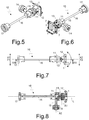
- the support 10 comprises a fastening device 11 suitable to be joined to at least one piece 1 to be treated, for example by means of a base 12 provided with threaded holes for the screws 7. Further means for fixing the piece 1 to the fastening device 11 can include vices, magnets or other mechanisms.
- the fastening device 11 may comprise at least one articulation 13 suitable to rotate the piece 1 (in the direction of the arrow of figure 7 ) around a first axis A1 and lock it in a desired position.
- the movable portion of the articulation 13 is joined to the base 12.
- the fastening device 11 may also comprise at least one counterweight 14 which protrudes from the support 10 along a second axis A2.
- the counterweight 14 comprises an arm 15 and is adapted to move the center of gravity of the fastening device 11 with the piece 1.
- the position of the arm 15 can be modified in the fastening device 11, so as to modify the position of the axis A2 with respect to the piece 1.
- the axis A2 can be rotated in various positions lying on a plane parallel to the axis A1.
- the counterweight 14 can comprise one or more rings, for example having a mass of about 0,5 kg.
- the fastening device 11 is connected through at least one elastic member 16 to at least one joint 17 suitable to be fixed to a vibrating body, for example by means of a flange integral with the joint 17.
- the fastening device 11 and/or the joint 17 are preferably fixed respectively to two ends of the elastic member 16, in particular in a removable manner, for example by means of jaws.
- the jaws of the fastening device 11 and/or of the joint 17 have a shape complementary to the section of the elastic member 16.
- the elastic member 16 extends along a longitudinal axis L and preferably comprises only a rectilinear bar which can be full or hollow with a polygonal, circular or elliptical section, in particular with a square section.
- the elastic member 16 may have shapes other than a rectilinear bar, for example a helical shape and/or may be formed by several parts which are joined to each other.
- the elastic member 16 is preferably made of metal, in particular spring steel.
- the elastic member 16 can flex and/or twist if the joint 17 is vibrated with an amplitude X1 and a frequency F1, so that the fastening device 11 can vibrate with an amplitude X2 and/or a frequency F2 different from those of the joint 17.
- the elastic member 16 preferably has a length of between 100 and 300 mm, in particular between 150 and 250 mm, and can be replaced with another elastic member having a different length by acting on the jaws of the fastening device 11 and of the joint 17.
- the first axis A1 of the articulation 13 and/or the second axis A2 of the counterweight 14 are substantially perpendicular to the longitudinal axis L of the elastic member 16.
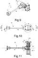
- the support 10 differs from the first embodiment in that the fastening device 11 includes also an actuator suitable to rotate the piece 1 around a third axis A3.
- This actuator may comprise a driven shaft 18 adapted to be operated by an electric motor 19 fixed to the fastening device 11.
- the driven shaft 18 can be connected to the base 12 directly or through the articulation 13, if present.
- the first axis A1 of the articulation 13, when the electric motor 19 is operating, rotates on a plane substantially parallel to the longitudinal axis L of the elastic member 16.
- the third axis A3 is substantially perpendicular to the longitudinal axis L of the elastic member 16.
- the base 12 cannot be arranged along the longitudinal axis L of the elastic member 16 as in the first embodiment of the support 10 but can protrude from one side of the fastening device 11, so that the axis longitudinal L does not pass through the piece 1.
- the support 10 differs from the second embodiment in that the fastening device 11 comprises, in addition or as an alternative to the articulation 13, a vibrator 20 suitable to vibrate the piece 1 around and/or along one or more axes.
- the vibrator 20 may comprise a plurality of exciters, in particular four 25 W electric exciters, which can vibrate at a frequency of 1000-5000 Hz and/or are contained in a housing arranged between the base 12 and the driven shaft 18.
- the support 10 according to a fourth embodiment differs from the second embodiment in that the driven shaft 18 of the actuator suitable to rotate the piece 1 around the third axis A3 can be operated, instead of the motor 19, by a rotor 21 provided with blades and adapted to be driven in turn by the motion of abrasive elements arranged in a vibrating tank.
- the support 10 differs from the second embodiment in that the driven shaft 18 of the actuator suitable to rotate the piece 1 around the third axis A3 can be operated by an electric motor 19 through a transmission comprising a transmission shaft 22 arranged coaxially in the elastic member 16, which is hollow.
- the transmission may further comprise a bevel gear 23 which is arranged in the fastening device 11 and is suitable to transmit the rotary motion from the transmission shaft 22 to the driven shaft 18.
- the electric motor 19 may be fixed to the joint 17.
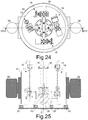
- the vibrating body 30 is preferably fixed to the vibrating tank 31, so that the vibrating body 30 can vibrate together with the vibrating tank 31 when the latter is driven by one or more vibrators 32, in particular two vibrators (not shown in the figure 23 ) which are driven by an electric motor and are fixed on an external surface, in particular a lateral surface, of the vibrating tank 31.
- the vibrators are shown solid for simplicity.
- the vibrating tank 31 may have a substantially cylindrical or annular shape with the central axis C oriented in a substantially vertical manner.
- the longitudinal axis L of the elastic members 16 of the supports 10 is substantially parallel to the central axis C of the vibrating tank 31.
- the vibrating tank 31 rests on one or more shock absorbers 33.
- the vibrating body 30 may comprise a frame, for example cross-shaped, which is arranged over the vibrating tank 31.
- the joints 17 of the supports 10 may be fixed to the vibrating body 30 by means of screws.
- the vibrating body 30 is joined to a spacer 34, in particular a shaft, which connects the vibrating body 30 to the vibrating tank 31.
- the spacer 34 is preferably fixed in a central area of the vibrating tank 31, so that the central axis C of the vibrating tank 31 passes through the spacer 34, in particular coaxially.
- the spacer 34 can be fixed to a dome 35 which protrudes from the base of the vibrating tank 31.
- joints 17 of two supports 10 may be joined to each other through a vibrating body 40, in particular a sleeve provided with a central hole, so that the longitudinal axes L of the elastic members 16 of the supports 10 are substantially aligned to each other.
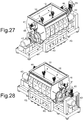
- the joints 17 of two pairs of supports 10 are fixed to two vibrating bodies 40 of figure 26 , so that the pieces 1 fixed to the supports 10 can be arranged in a vibrating tank 41 of a second embodiment of a machine which can be filled with abrasive elements (not shown in the figures) to treat the pieces 1 joined to the supports 10.
- the vibrating bodies 40 are preferably fixed to the vibrating tank 41, so that the vibrating bodies 40 vibrate together with the vibrating tank 41, when the latter is operated by one or more vibrators 42, in particular two vibrators which are driven by an electric motor and are arranged outside the vibrating tank 41.
- the vibrating tank 41 has a substantially cylindrical shape with the central axis C oriented in a substantially horizontal manner and/or the longitudinal axis L of the elastic members 16 of the supports 10 is substantially perpendicular to the central axis C of the vibrating tank 41.
- the vibrating tank 41 rests on one or more shock absorbers 43.
- the vibrating bodies 40 are joined to a spacer 44, in particular a shaft, which connects the vibrating bodies 40 to the vibrating tank 41.
- the spacer 44 is preferably fixed in a central area of the vibrating tank 41, so that the central axis C of the vibrating tank 41 passes through the spacer 44, in particular coaxially.
- the spacer 44 can pass through at least one wall of the vibrating tank 41 to be connected to at least one motor 45 which is arranged outside the vibrating tank 41.
- the motor 45 can therefore rotate the spacer 44 around its own axis, in particular around the central axis C of the vibrating tank 41, so that the vibrating bodies 40 rotate the supports 10 and the pieces 1 can be located in the mass of the abrasive elements contained in the vibrating tank 41 or above this mass.
- Figure 30 shows a possible level M of the mass of the abrasive elements in the vibrating tank 41, with two pieces 1 arranged above and below this level M, respectively.
- the spacer 44 can be connected to one or more brakes 46, in particular disc brakes arranged outside the vibrating tank 41, suitable to prevent the rotation of the spacer 44, that is of the supports 10, around the axis C, since the movement of the abrasive elements in the vibrating tank 41 can induce this rotation even when the motor 45 is not working or is not present.
- brakes 46 in particular disc brakes arranged outside the vibrating tank 41, suitable to prevent the rotation of the spacer 44, that is of the supports 10, around the axis C, since the movement of the abrasive elements in the vibrating tank 41 can induce this rotation even when the motor 45 is not working or is not present.
- the vibrators 32, 42 can vibrate the vibrating tank 31, 41 at a main frequency MF up to 100 Hz, in particular between 25 Hz and 55 Hz.
- the main frequency MF of vibration of the vibrating bowl 31, 41 is adjusted so as to induce in the joints 17 of the supports 10 a vibration with an amplitude X1 at a vibration frequency F1 such that the amplitude X2 of the respective fastening devices 11, namely of the pieces 1, is greater than the amplitude X1 of the joints 17, namely X2>X1, and/or such that the vibration frequency F2 of the respective fastening devices 11 is equal to the vibration frequency F1 of the joints 17, within a range of ⁇ 50%, i.e.
- the vibration frequency F1 of the joints 17 is substantially equal to the main frequency FM of the vibration of the vibrating tank 31, 41.
- the particular vibration of the pieces 1 can be obtained by adjusting the position of the articulations 13, the position and/or mass of the counterweights 14, the length of the elastic elements 16, and/or the frequency of the vibrators 32, 42, depending on the weight and of the dimensions of each piece 1.
- the abrasive elements in the vibrating tank 31, 41 preferably have a substantially spherical shape with a diameter comprised between 60% and 90% of the diameter d of the ducts 2, 3 of the piece 1.
Landscapes
- Engineering & Computer Science (AREA)
- Mechanical Engineering (AREA)
- Finish Polishing, Edge Sharpening, And Grinding By Specific Grinding Devices (AREA)
- Coating With Molten Metal (AREA)
- Slide Fasteners, Snap Fasteners, And Hook Fasteners (AREA)
Abstract
Description
- The present description relates to a support for surface finishing, in particular a support that can be used to support a piece during a surface finishing thereof. The present description also relates to a machine and a process which can use such a support.
- Known machines for surface finishing comprise a vibrating tank that can contain pieces and abrasive elements suitable to treat the outer surface of these pieces when the tank is vibrated. The pieces and the abrasive elements are free to move in the vibrating tank, since they are not fastened to any support. Such known machines cannot treat the inner surface of the pieces homogeneously, especially if these comprise ducts of different shape and/or section, long and/or curved, such as those made with 3D printers, so that the final results of the surface finishing are unsatisfactory.
- The object of the present description is therefore to provide a machine which is free from these drawbacks. Said object is achieved with a particular support, a machine and a process, whose main features are specified in the attached claims.
- Thanks to the particular support for the pieces to be treated, the machine is able to perform a suitable finishing not only of the outer surface of the pieces but also of their inner surfaces, in particular long and/or curved ducts.
- The support is preferably fixed to the vibrating tank of the machine to vibrate with it and induce further vibrations to the piece, in particular vibrations close to the resonant frequency of the support, so as to optimize the effect of the vibrations for the surface finishing of the piece.
- The support preferably comprises at least one joint, a counterweight, a vibrator and/or an actuator to further improve the speed and/or quality of the surface finishing of the piece fixed to the support.
- The fastening device and/or the joint of the support can be fixed in a removable manner respectively to two ends of the elastic member, preferably a bar made of spring steel having a round or square section with a given length, so as to adapt the support to the particular piece to be treated.
- The machine preferably comprises means for rotating the support around an axis, in particular a substantially horizontal axis, so as to be able to arrange the piece both inside the mass of the abrasive elements and outside this mass, so as to adjust the processing times of the surface finishing, even for different pieces arranged in the same vibrating tank.
- The support and/or the machine preferably exploit the movement of the abrasive elements to rotate the pieces around one or more axes in the vibrating tank and/or above it.
- Further advantages and characteristics of the support, the machine and the process will become apparent to those skilled in the art from the following detailed and nonlimiting description of some embodiments thereof with reference to the accompanying drawings in which:
-
figure 1 shows a first axonometric view of a piece to be treated; -
figure 2 shows a second axonometric view of the piece offigure 1 ; -
figure 3 shows a front view of the piece offigure 1 ; -
figure 4 shows section IV-IV offigure 3 ; -
figure 5 shows a first axonometric view of a first embodiment of the support with the piece offigure 1 ; -
figure 6 shows a second axonometric view of the support offigure 5 ; -
figure 7 shows a side view of the support offigure 5 ; -
figure 8 shows section VIII-VIII offigure 7 ; -
figure 9 shows an axonometric view of a second embodiment of the support with the piece offigure 1 ; -
figure 10 shows a side view of the support offigure 9 ; -
figure 11 shows section XI-XI offigure 10 ; -
figure 12 shows an axonometric view of a third embodiment of the support with the piece offigure 1 ; -
figure 13 shows a side view of the support offigure 12 ; -
figure 14 shows section XIV-XIV offigure 13 ; -
figure 15 shows a first axonometric view of a fourth embodiment of the support with the piece offigure 1 ; -
figure 16 shows a second axonometric view of the support offigure 15 ; -
figure 17 shows a side view of the support offigure 15 ; -
figure 18 shows section XVIII-XVIII offigure 17 ; -
figure 19 shows a front view of the support offigure 15 ; -
figure 20 shows an axonometric view of a fifth embodiment of the support with the piece offigure 1 ; -
figure 21 shows a side view of the support offigure 20 ; -
figure 22 shows section XXII-XXII offigure 21 ; -
figure 23 shows an axonometric view of the sole vibrating tank of a first embodiment of the machine; -
figure 24 shows a top view of the machine offigure 23 ; -
figure 25 shows section XXV-XXV offigure 24 ; -
figure 26 shows a vibrating body with two supports according to the first embodiment; -
figure 27 shows a first axonometric view of a second embodiment of the machine; -
figure 28 shows a second axonometric view of the machine offigure 27 ; -
figure 29 shows a top view of the machine offigure 27 ; -
figure 30 shows section XXX-XXX offigure 29 ; -
figure 31 shows section XXXI-XXXI offigure 29 . - Referring to
figures 1 to 4 , it is seen that apiece 1 to be subjected to surface finishing may comprise one ormore ducts piece 1 at one or both ends and present one ormore bends piece 1, for example abend 4 of 180° and twobends 5 of 90° in theduct 3 and abend 5 of 90° in theduct 2. Thepiece 1 can also comprise one ormore openings 6, for example four slots, to house the shank of a screw 7 (only the respective head is shown with dashed lines in the figures). Theducts - With reference to
figures 5 to 8 , it is seen that thesupport 10 according to a first embodiment comprises afastening device 11 suitable to be joined to at least onepiece 1 to be treated, for example by means of abase 12 provided with threaded holes for thescrews 7. Further means for fixing thepiece 1 to thefastening device 11 can include vices, magnets or other mechanisms. Thefastening device 11 may comprise at least onearticulation 13 suitable to rotate the piece 1 (in the direction of the arrow offigure 7 ) around a first axis A1 and lock it in a desired position. The movable portion of thearticulation 13 is joined to thebase 12. Thefastening device 11 may also comprise at least onecounterweight 14 which protrudes from thesupport 10 along a second axis A2. Thecounterweight 14 comprises anarm 15 and is adapted to move the center of gravity of thefastening device 11 with thepiece 1. The position of thearm 15 can be modified in thefastening device 11, so as to modify the position of the axis A2 with respect to thepiece 1. In particular, by acting on jaws arranged at the end of thearm 15 opposite to thecounterweight 14, the axis A2 can be rotated in various positions lying on a plane parallel to the axis A1. Thecounterweight 14 can comprise one or more rings, for example having a mass of about 0,5 kg. - The
fastening device 11 is connected through at least oneelastic member 16 to at least onejoint 17 suitable to be fixed to a vibrating body, for example by means of a flange integral with thejoint 17. Thefastening device 11 and/or thejoint 17 are preferably fixed respectively to two ends of theelastic member 16, in particular in a removable manner, for example by means of jaws. The jaws of thefastening device 11 and/or of thejoint 17 have a shape complementary to the section of theelastic member 16. Theelastic member 16 extends along a longitudinal axis L and preferably comprises only a rectilinear bar which can be full or hollow with a polygonal, circular or elliptical section, in particular with a square section. In other embodiments, theelastic member 16 may have shapes other than a rectilinear bar, for example a helical shape and/or may be formed by several parts which are joined to each other. Theelastic member 16 is preferably made of metal, in particular spring steel. Theelastic member 16 can flex and/or twist if the joint 17 is vibrated with an amplitude X1 and a frequency F1, so that thefastening device 11 can vibrate with an amplitude X2 and/or a frequency F2 different from those of the joint 17. Theelastic member 16 preferably has a length of between 100 and 300 mm, in particular between 150 and 250 mm, and can be replaced with another elastic member having a different length by acting on the jaws of thefastening device 11 and of the joint 17. The first axis A1 of thearticulation 13 and/or the second axis A2 of thecounterweight 14 are substantially perpendicular to the longitudinal axis L of theelastic member 16. - Referring to
figures 9 to 11 , it is seen that thesupport 10 according to a second embodiment differs from the first embodiment in that thefastening device 11 includes also an actuator suitable to rotate thepiece 1 around a third axis A3. This actuator may comprise a drivenshaft 18 adapted to be operated by anelectric motor 19 fixed to thefastening device 11. The drivenshaft 18 can be connected to the base 12 directly or through thearticulation 13, if present. The first axis A1 of thearticulation 13, when theelectric motor 19 is operating, rotates on a plane substantially parallel to the longitudinal axis L of theelastic member 16. The third axis A3 is substantially perpendicular to the longitudinal axis L of theelastic member 16. The base 12 cannot be arranged along the longitudinal axis L of theelastic member 16 as in the first embodiment of thesupport 10 but can protrude from one side of thefastening device 11, so that the axis longitudinal L does not pass through thepiece 1. - Referring to
figures 12 to 14 , it is seen that thesupport 10 according to a third embodiment differs from the second embodiment in that thefastening device 11 comprises, in addition or as an alternative to thearticulation 13, avibrator 20 suitable to vibrate thepiece 1 around and/or along one or more axes. Thevibrator 20 may comprise a plurality of exciters, in particular four 25 W electric exciters, which can vibrate at a frequency of 1000-5000 Hz and/or are contained in a housing arranged between the base 12 and the drivenshaft 18. - With reference to
figures 15 to 19 , it is seen that thesupport 10 according to a fourth embodiment differs from the second embodiment in that the drivenshaft 18 of the actuator suitable to rotate thepiece 1 around the third axis A3 can be operated, instead of themotor 19, by arotor 21 provided with blades and adapted to be driven in turn by the motion of abrasive elements arranged in a vibrating tank. - With reference to
figures 20 to 22 , it is seen that thesupport 10 according to a fifth embodiment differs from the second embodiment in that the drivenshaft 18 of the actuator suitable to rotate thepiece 1 around the third axis A3 can be operated by anelectric motor 19 through a transmission comprising atransmission shaft 22 arranged coaxially in theelastic member 16, which is hollow. The transmission may further comprise abevel gear 23 which is arranged in thefastening device 11 and is suitable to transmit the rotary motion from thetransmission shaft 22 to the drivenshaft 18. Theelectric motor 19 may be fixed to the joint 17. - With reference to
figures 23 to 25 , it is seen that thejoints 17 of four supports 10 (in particular according to the first, second, third and fourth embodiments) are fixed to a vibratingbody 30, so that thepieces 1 fixed thesupports 10 are arranged in a vibratingtank 31 of a first embodiment of a machine which can be filled with abrasive elements (not shown in the figures) for the surface finishing of thepieces 1 joined to thesupports 10. The vibratingbody 30 is preferably fixed to the vibratingtank 31, so that the vibratingbody 30 can vibrate together with the vibratingtank 31 when the latter is driven by one ormore vibrators 32, in particular two vibrators (not shown in thefigure 23 ) which are driven by an electric motor and are fixed on an external surface, in particular a lateral surface, of the vibratingtank 31. In the figures, the vibrators are shown solid for simplicity. The vibratingtank 31 may have a substantially cylindrical or annular shape with the central axis C oriented in a substantially vertical manner. The longitudinal axis L of theelastic members 16 of thesupports 10 is substantially parallel to the central axis C of the vibratingtank 31. The vibratingtank 31 rests on one ormore shock absorbers 33. - The vibrating
body 30 may comprise a frame, for example cross-shaped, which is arranged over the vibratingtank 31. Thejoints 17 of thesupports 10 may be fixed to the vibratingbody 30 by means of screws. The vibratingbody 30 is joined to aspacer 34, in particular a shaft, which connects the vibratingbody 30 to the vibratingtank 31. Thespacer 34 is preferably fixed in a central area of the vibratingtank 31, so that the central axis C of the vibratingtank 31 passes through thespacer 34, in particular coaxially. In particular, thespacer 34 can be fixed to adome 35 which protrudes from the base of the vibratingtank 31. - With reference to
figure 26 , it is seen that thejoints 17 of two supports 10 (in particular according to the first embodiment) may be joined to each other through a vibratingbody 40, in particular a sleeve provided with a central hole, so that the longitudinal axes L of theelastic members 16 of thesupports 10 are substantially aligned to each other. - With reference to
figures 27 to 31 , it is seen that thejoints 17 of two pairs ofsupports 10 are fixed to two vibratingbodies 40 offigure 26 , so that thepieces 1 fixed to thesupports 10 can be arranged in a vibratingtank 41 of a second embodiment of a machine which can be filled with abrasive elements (not shown in the figures) to treat thepieces 1 joined to thesupports 10. The vibratingbodies 40 are preferably fixed to the vibratingtank 41, so that the vibratingbodies 40 vibrate together with the vibratingtank 41, when the latter is operated by one ormore vibrators 42, in particular two vibrators which are driven by an electric motor and are arranged outside the vibratingtank 41. The vibratingtank 41 has a substantially cylindrical shape with the central axis C oriented in a substantially horizontal manner and/or the longitudinal axis L of theelastic members 16 of thesupports 10 is substantially perpendicular to the central axis C of the vibratingtank 41. The vibratingtank 41 rests on one ormore shock absorbers 43. - The vibrating
bodies 40 are joined to aspacer 44, in particular a shaft, which connects the vibratingbodies 40 to the vibratingtank 41. Thespacer 44 is preferably fixed in a central area of the vibratingtank 41, so that the central axis C of the vibratingtank 41 passes through thespacer 44, in particular coaxially. Thespacer 44 can pass through at least one wall of the vibratingtank 41 to be connected to at least onemotor 45 which is arranged outside the vibratingtank 41. Themotor 45 can therefore rotate thespacer 44 around its own axis, in particular around the central axis C of the vibratingtank 41, so that the vibratingbodies 40 rotate thesupports 10 and thepieces 1 can be located in the mass of the abrasive elements contained in the vibratingtank 41 or above this mass.Figure 30 shows a possible level M of the mass of the abrasive elements in the vibratingtank 41, with twopieces 1 arranged above and below this level M, respectively. Thespacer 44 can be connected to one ormore brakes 46, in particular disc brakes arranged outside the vibratingtank 41, suitable to prevent the rotation of thespacer 44, that is of thesupports 10, around the axis C, since the movement of the abrasive elements in the vibratingtank 41 can induce this rotation even when themotor 45 is not working or is not present. - In the surface finishing process of the
pieces 1, thevibrators tank bowl joints 17 of the supports 10 a vibration with an amplitude X1 at a vibration frequency F1 such that the amplitude X2 of therespective fastening devices 11, namely of thepieces 1, is greater than the amplitude X1 of thejoints 17, namely X2>X1, and/or such that the vibration frequency F2 of therespective fastening devices 11 is equal to the vibration frequency F1 of thejoints 17, within a range of ± 50%, i.e. 0,5<F1/F2 <1,5. In particular, the vibration frequency F1 of thejoints 17 is substantially equal to the main frequency FM of the vibration of the vibratingtank pieces 1 can be obtained by adjusting the position of thearticulations 13, the position and/or mass of thecounterweights 14, the length of theelastic elements 16, and/or the frequency of thevibrators piece 1. The abrasive elements in the vibratingtank ducts piece 1. - Any variants or additions may be made by those skilled in the art to the embodiments herein described and illustrated, while remaining within the scope of the following claims. In particular, further embodiments may comprise the technical features of one of the following claims with the addition of one or more technical features described in the text or illustrated in the drawings, taken individually or in any mutual combination thereof.
Claims (20)
- Support (10), characterized in that it comprises a fastening device (11) which is suitable to be joined to at least one piece (1) to be treated in a vibrating tank (31; 41) and is connected through at least one elastic member (16) to at least one joint (17) suitable to be fixed to a vibrating body (30, 40), wherein the elastic member (16) extends along a longitudinal axis (L), so that the elastic member (16) can flex and/or twist if the joint (17) is vibrated.
- Support (10) according to the previous claim, characterized in that the fastening device (11) comprises at least one articulation (13) suitable to rotate the piece (1) around an axis (A1) and to lock it in a desired position.
- Support (10) according to one of the previous claims, characterized in that the fastening device (11) comprises at least one counterweight (14) which projects along an axis (A2).
- Support (10) according to one of the previous claims, characterized in that the fastening device (11) comprises an actuator (18) suitable to rotate the piece (1) around an axis (A3).
- Support (10) according to the previous claim, characterized in that the actuator (18) comprises a driven shaft (18) suitable to be rotated by a rotor (21) provided with blades or by an electric motor (19) fixed to the fastening device (11) or to the joint (17).
- Support (10) according to one of claims 2 to 5, characterized in that the rotation axis (A1) of the articulation (13) and/or the axis (A2) of the counterweight (14) and/or the rotation axis (A3) of the actuator (18) are substantially perpendicular to the longitudinal axis (L) of the elastic member (16).
- Support (10) according to one of the previous claims, characterized in that the fastening device (11) comprises a vibrator (20) suitable to vibrate the piece (1) around and/or along one or more axes.
- Support (10) according to one of the previous claims, characterized in that the fastening device (11) and/or the joint (17) are fixed respectively at two ends of the elastic member (16) in a removable manner.
- Machine comprising a vibrating tank (31; 41) suitable to contain at least one piece (1) to be treated, characterized in that the machine also comprises at least one support (10) according to one of the previous claims.
- Machine according to the previous claim, characterized in that the vibrating tank (31; 41) has a substantially cylindrical or annular shape with a central axis (C) and that the longitudinal axis (L) of the support (10) is substantially parallel or substantially perpendicular to this central axis (C).
- Machine according to claim 9 or 10, characterized in that the support (10) can rotate in the vibrating tank (41) around a substantially horizontal axis (C).
- Machine according to one of the claims from 9 to 11, characterized in that the joint (17) of the support (10) is fixed to at least one vibrating body (30; 40) suitable to vibrate when the vibrating tank (31; 41) is driven by one or more vibrators (32; 42).
- Machine according to the previous claim, characterized in that the vibrating body (30; 40) is fixed to the vibrating tank (31; 41) by means of at least one spacer (34; 44), so that the vibrating body (30; 40) can vibrate together with the vibrating tank (31; 41).
- Machine according to the previous claim, characterized in that the spacer (44) is suitable to rotate around an axis (C) by means of at least one motor (45) and/or the movement of abrasive members arranged in the vibrating tank (31; 41).
- Machine according to the previous claim, characterized in that the spacer (44) is connected to one or more brakes (46) suitable to prevent the rotation of the spacer (44) around the axis (C).
- Process for the surface finishing of at least one piece (1) in a vibrating tank (31; 41), characterized in that it comprises the following operating steps:- fastening the piece (1) to a support (10) according to one of the claims 1 to 8;- arranging the piece (1) fastened to the support (10) in a vibrating tank (31; 41) together with abrasive members, wherein the vibrating tank (31, 41) vibrates at a main frequency (MF);- vibrating the joint (17) of the support (10).
- Process according to the previous claim, characterized in that the joint (17) of the support (10) vibrates with an amplitude (X1) at a vibration frequency (F1) such that the amplitude (X2) of the vibration of the fastening device (11) of the support (10) is greater than the amplitude (X1) of the vibration of the joint (17) and/or such that the vibration frequency (F2) of the fastening device (11) is equal to the vibration frequency (F1) of the joint (17), within a range of ± 50%.
- Process according to the previous claim, characterized in that the vibration frequency (F1) of the joint (17) is substantially equal to the main frequency (FM) of the vibration of the vibrating tank (31; 41).
- Process according to one of claims 16 to 18, characterized in that the abrasive elements in the vibrating tank (31; 41) have a substantially spherical shape with a diameter of 60% to 90% of the diameter (d) of ducts (2, 3) present in the piece (1).
- Process according to one of claims 16 to 19, characterized in that the vibrating tank (31; 41) belongs to a machine according to one of claims 9 to 15.
Applications Claiming Priority (1)
| Application Number | Priority Date | Filing Date | Title |
|---|---|---|---|
| IT102018000009904A IT201800009904A1 (en) | 2018-10-30 | 2018-10-30 | Support, machine and process for surface finishes |
Publications (2)
| Publication Number | Publication Date |
|---|---|
| EP3646988A1 true EP3646988A1 (en) | 2020-05-06 |
| EP3646988B1 EP3646988B1 (en) | 2021-07-28 |
Family
ID=67875817
Family Applications (1)
| Application Number | Title | Priority Date | Filing Date |
|---|---|---|---|
| EP19205910.3A Active EP3646988B1 (en) | 2018-10-30 | 2019-10-29 | Support, machine and process for surface finishing |
Country Status (2)
| Country | Link |
|---|---|
| EP (1) | EP3646988B1 (en) |
| IT (1) | IT201800009904A1 (en) |
Cited By (2)
| Publication number | Priority date | Publication date | Assignee | Title |
|---|---|---|---|---|
| CN115446723A (en) * | 2022-10-14 | 2022-12-09 | 王虞西 | A kind of burr grinding system and grinding method for processing aluminum alloy doors and windows |
| CN116100455A (en) * | 2023-03-20 | 2023-05-12 | 西安航天动力研究所 | A longitudinal polishing device and longitudinal polishing method for a fatigue sample |
Citations (7)
| Publication number | Priority date | Publication date | Assignee | Title |
|---|---|---|---|---|
| EP0598369A1 (en) * | 1992-11-19 | 1994-05-25 | RENI-CIRILLO S.r.l. | Device for the finishing of hanging parts by means of a vibrating machine |
| US20120021674A1 (en) * | 2010-07-21 | 2012-01-26 | Gert Schroeter | Grinding or polishing apparatus and method for operating it |
| CN104647189A (en) * | 2015-01-26 | 2015-05-27 | 上海交通大学 | Device for mechanically grinding magnesium alloy and grinding method based on device |
| EP3098026A1 (en) * | 2015-05-29 | 2016-11-30 | Rolls-Royce plc | Vibratory finishing apparatus, fixtures and methods |
| TWI568537B (en) * | 2016-09-08 | 2017-02-01 | Vibration grinding machine structure | |
| WO2018082776A1 (en) * | 2016-11-03 | 2018-05-11 | Swisssurface.Ch Sa | Surface treatment device and surface treatment method using such a device |
| CN108214272A (en) * | 2017-12-29 | 2018-06-29 | 浙江工业大学 | A kind of centrifugal pump impeller cover board polishing method and its burnishing device |
-
2018
- 2018-10-30 IT IT102018000009904A patent/IT201800009904A1/en unknown
-
2019
- 2019-10-29 EP EP19205910.3A patent/EP3646988B1/en active Active
Patent Citations (7)
| Publication number | Priority date | Publication date | Assignee | Title |
|---|---|---|---|---|
| EP0598369A1 (en) * | 1992-11-19 | 1994-05-25 | RENI-CIRILLO S.r.l. | Device for the finishing of hanging parts by means of a vibrating machine |
| US20120021674A1 (en) * | 2010-07-21 | 2012-01-26 | Gert Schroeter | Grinding or polishing apparatus and method for operating it |
| CN104647189A (en) * | 2015-01-26 | 2015-05-27 | 上海交通大学 | Device for mechanically grinding magnesium alloy and grinding method based on device |
| EP3098026A1 (en) * | 2015-05-29 | 2016-11-30 | Rolls-Royce plc | Vibratory finishing apparatus, fixtures and methods |
| TWI568537B (en) * | 2016-09-08 | 2017-02-01 | Vibration grinding machine structure | |
| WO2018082776A1 (en) * | 2016-11-03 | 2018-05-11 | Swisssurface.Ch Sa | Surface treatment device and surface treatment method using such a device |
| CN108214272A (en) * | 2017-12-29 | 2018-06-29 | 浙江工业大学 | A kind of centrifugal pump impeller cover board polishing method and its burnishing device |
Cited By (3)
| Publication number | Priority date | Publication date | Assignee | Title |
|---|---|---|---|---|
| CN115446723A (en) * | 2022-10-14 | 2022-12-09 | 王虞西 | A kind of burr grinding system and grinding method for processing aluminum alloy doors and windows |
| CN115446723B (en) * | 2022-10-14 | 2024-05-28 | 山东德信门窗有限公司 | A burr grinding system and grinding method for aluminum alloy door and window processing |
| CN116100455A (en) * | 2023-03-20 | 2023-05-12 | 西安航天动力研究所 | A longitudinal polishing device and longitudinal polishing method for a fatigue sample |
Also Published As
| Publication number | Publication date |
|---|---|
| EP3646988B1 (en) | 2021-07-28 |
| IT201800009904A1 (en) | 2020-04-30 |
Similar Documents
| Publication | Publication Date | Title |
|---|---|---|
| RU2477660C2 (en) | Laboratory jar mill with inclined milling cups | |
| AU2002352769B2 (en) | Exciter mass assembly for a vibratory device | |
| EP3646988B1 (en) | Support, machine and process for surface finishing | |
| US4007825A (en) | Vibratory parts feeder driven by rotating eccentric weights | |
| EP3107687B1 (en) | Improved mandrel for sizing, smoothing or polishing stone materials with rotating abrasive heads | |
| AU2002352769A1 (en) | Exciter mass assembly for a vibratory device | |
| KR101909808B1 (en) | Metronome-type vibration controlling device | |
| JPH06114717A (en) | Manual grinding device with vibration damper | |
| RU2501608C2 (en) | Vibratory mill | |
| US4472980A (en) | Motor actuated rotary vibrator with resilient shock mount to provide linear movement | |
| CN107042201A (en) | Adjustable amplitude vibratory sieve | |
| US4389120A (en) | Rotary vibrator with resilient shock mount to provide linear movement | |
| JP2002521224A (en) | Polishing equipment for curved surfaces | |
| CN101934270A (en) | Vibrating screen | |
| JP2007326215A (en) | Hand tool device | |
| JPH0725018B2 (en) | Polishing head for stone | |
| CN106461001B (en) | Rotary damper | |
| CN102274822B (en) | Elliptic vibration machine with parallel shafts and double excitation motors | |
| CN104689984A (en) | Mono-axial workable vibrating sieve | |
| CN102554884A (en) | Power tool | |
| KR20090003929U (en) | Vibration device of horizontal vibrating screen | |
| JPH06221323A (en) | Revolution-body axial supporter and positioning device with said supporter | |
| RU2314159C1 (en) | Vibroimpact crushing device | |
| JPS6350151B2 (en) | ||
| CN114221487B (en) | Low-interference type vibration motor with adjustable vibration area |
Legal Events
| Date | Code | Title | Description |
|---|---|---|---|
| PUAI | Public reference made under article 153(3) epc to a published international application that has entered the european phase |
Free format text: ORIGINAL CODE: 0009012 |
|
| STAA | Information on the status of an ep patent application or granted ep patent |
Free format text: STATUS: THE APPLICATION HAS BEEN PUBLISHED |
|
| AK | Designated contracting states |
Kind code of ref document: A1 Designated state(s): AL AT BE BG CH CY CZ DE DK EE ES FI FR GB GR HR HU IE IS IT LI LT LU LV MC MK MT NL NO PL PT RO RS SE SI SK SM TR |
|
| AX | Request for extension of the european patent |
Extension state: BA ME |
|
| STAA | Information on the status of an ep patent application or granted ep patent |
Free format text: STATUS: REQUEST FOR EXAMINATION WAS MADE |
|
| 17P | Request for examination filed |
Effective date: 20201103 |
|
| RBV | Designated contracting states (corrected) |
Designated state(s): AL AT BE BG CH CY CZ DE DK EE ES FI FR GB GR HR HU IE IS IT LI LT LU LV MC MK MT NL NO PL PT RO RS SE SI SK SM TR |
|
| GRAP | Despatch of communication of intention to grant a patent |
Free format text: ORIGINAL CODE: EPIDOSNIGR1 |
|
| STAA | Information on the status of an ep patent application or granted ep patent |
Free format text: STATUS: GRANT OF PATENT IS INTENDED |
|
| INTG | Intention to grant announced |
Effective date: 20210208 |
|
| GRAS | Grant fee paid |
Free format text: ORIGINAL CODE: EPIDOSNIGR3 |
|
| GRAA | (expected) grant |
Free format text: ORIGINAL CODE: 0009210 |
|
| STAA | Information on the status of an ep patent application or granted ep patent |
Free format text: STATUS: THE PATENT HAS BEEN GRANTED |
|
| AK | Designated contracting states |
Kind code of ref document: B1 Designated state(s): AL AT BE BG CH CY CZ DE DK EE ES FI FR GB GR HR HU IE IS IT LI LT LU LV MC MK MT NL NO PL PT RO RS SE SI SK SM TR |
|
| RAP1 | Party data changed (applicant data changed or rights of an application transferred) |
Owner name: ROESLER ITALIANA S.R.L. |
|
| REG | Reference to a national code |
Ref country code: GB Ref legal event code: FG4D |
|
| REG | Reference to a national code |
Ref country code: CH Ref legal event code: EP |
|
| REG | Reference to a national code |
Ref country code: AT Ref legal event code: REF Ref document number: 1414289 Country of ref document: AT Kind code of ref document: T Effective date: 20210815 |
|
| REG | Reference to a national code |
Ref country code: IE Ref legal event code: FG4D |
|
| REG | Reference to a national code |
Ref country code: DE Ref legal event code: R096 Ref document number: 602019006417 Country of ref document: DE |
|
| REG | Reference to a national code |
Ref country code: LT Ref legal event code: MG9D |
|
| REG | Reference to a national code |
Ref country code: NL Ref legal event code: MP Effective date: 20210728 |
|
| REG | Reference to a national code |
Ref country code: AT Ref legal event code: MK05 Ref document number: 1414289 Country of ref document: AT Kind code of ref document: T Effective date: 20210728 |
|
| PG25 | Lapsed in a contracting state [announced via postgrant information from national office to epo] |
Ref country code: HR Free format text: LAPSE BECAUSE OF FAILURE TO SUBMIT A TRANSLATION OF THE DESCRIPTION OR TO PAY THE FEE WITHIN THE PRESCRIBED TIME-LIMIT Effective date: 20210728 Ref country code: FI Free format text: LAPSE BECAUSE OF FAILURE TO SUBMIT A TRANSLATION OF THE DESCRIPTION OR TO PAY THE FEE WITHIN THE PRESCRIBED TIME-LIMIT Effective date: 20210728 Ref country code: PT Free format text: LAPSE BECAUSE OF FAILURE TO SUBMIT A TRANSLATION OF THE DESCRIPTION OR TO PAY THE FEE WITHIN THE PRESCRIBED TIME-LIMIT Effective date: 20211129 Ref country code: NL Free format text: LAPSE BECAUSE OF FAILURE TO SUBMIT A TRANSLATION OF THE DESCRIPTION OR TO PAY THE FEE WITHIN THE PRESCRIBED TIME-LIMIT Effective date: 20210728 Ref country code: NO Free format text: LAPSE BECAUSE OF FAILURE TO SUBMIT A TRANSLATION OF THE DESCRIPTION OR TO PAY THE FEE WITHIN THE PRESCRIBED TIME-LIMIT Effective date: 20211028 Ref country code: BG Free format text: LAPSE BECAUSE OF FAILURE TO SUBMIT A TRANSLATION OF THE DESCRIPTION OR TO PAY THE FEE WITHIN THE PRESCRIBED TIME-LIMIT Effective date: 20211028 Ref country code: AT Free format text: LAPSE BECAUSE OF FAILURE TO SUBMIT A TRANSLATION OF THE DESCRIPTION OR TO PAY THE FEE WITHIN THE PRESCRIBED TIME-LIMIT Effective date: 20210728 Ref country code: LT Free format text: LAPSE BECAUSE OF FAILURE TO SUBMIT A TRANSLATION OF THE DESCRIPTION OR TO PAY THE FEE WITHIN THE PRESCRIBED TIME-LIMIT Effective date: 20210728 Ref country code: RS Free format text: LAPSE BECAUSE OF FAILURE TO SUBMIT A TRANSLATION OF THE DESCRIPTION OR TO PAY THE FEE WITHIN THE PRESCRIBED TIME-LIMIT Effective date: 20210728 Ref country code: SE Free format text: LAPSE BECAUSE OF FAILURE TO SUBMIT A TRANSLATION OF THE DESCRIPTION OR TO PAY THE FEE WITHIN THE PRESCRIBED TIME-LIMIT Effective date: 20210728 Ref country code: ES Free format text: LAPSE BECAUSE OF FAILURE TO SUBMIT A TRANSLATION OF THE DESCRIPTION OR TO PAY THE FEE WITHIN THE PRESCRIBED TIME-LIMIT Effective date: 20210728 |
|
| PG25 | Lapsed in a contracting state [announced via postgrant information from national office to epo] |
Ref country code: PL Free format text: LAPSE BECAUSE OF FAILURE TO SUBMIT A TRANSLATION OF THE DESCRIPTION OR TO PAY THE FEE WITHIN THE PRESCRIBED TIME-LIMIT Effective date: 20210728 Ref country code: LV Free format text: LAPSE BECAUSE OF FAILURE TO SUBMIT A TRANSLATION OF THE DESCRIPTION OR TO PAY THE FEE WITHIN THE PRESCRIBED TIME-LIMIT Effective date: 20210728 Ref country code: GR Free format text: LAPSE BECAUSE OF FAILURE TO SUBMIT A TRANSLATION OF THE DESCRIPTION OR TO PAY THE FEE WITHIN THE PRESCRIBED TIME-LIMIT Effective date: 20211029 |
|
| PG25 | Lapsed in a contracting state [announced via postgrant information from national office to epo] |
Ref country code: DK Free format text: LAPSE BECAUSE OF FAILURE TO SUBMIT A TRANSLATION OF THE DESCRIPTION OR TO PAY THE FEE WITHIN THE PRESCRIBED TIME-LIMIT Effective date: 20210728 |
|
| REG | Reference to a national code |
Ref country code: DE Ref legal event code: R097 Ref document number: 602019006417 Country of ref document: DE |
|
| PG25 | Lapsed in a contracting state [announced via postgrant information from national office to epo] |
Ref country code: SM Free format text: LAPSE BECAUSE OF FAILURE TO SUBMIT A TRANSLATION OF THE DESCRIPTION OR TO PAY THE FEE WITHIN THE PRESCRIBED TIME-LIMIT Effective date: 20210728 Ref country code: SK Free format text: LAPSE BECAUSE OF FAILURE TO SUBMIT A TRANSLATION OF THE DESCRIPTION OR TO PAY THE FEE WITHIN THE PRESCRIBED TIME-LIMIT Effective date: 20210728 Ref country code: RO Free format text: LAPSE BECAUSE OF FAILURE TO SUBMIT A TRANSLATION OF THE DESCRIPTION OR TO PAY THE FEE WITHIN THE PRESCRIBED TIME-LIMIT Effective date: 20210728 Ref country code: EE Free format text: LAPSE BECAUSE OF FAILURE TO SUBMIT A TRANSLATION OF THE DESCRIPTION OR TO PAY THE FEE WITHIN THE PRESCRIBED TIME-LIMIT Effective date: 20210728 Ref country code: CZ Free format text: LAPSE BECAUSE OF FAILURE TO SUBMIT A TRANSLATION OF THE DESCRIPTION OR TO PAY THE FEE WITHIN THE PRESCRIBED TIME-LIMIT Effective date: 20210728 Ref country code: AL Free format text: LAPSE BECAUSE OF FAILURE TO SUBMIT A TRANSLATION OF THE DESCRIPTION OR TO PAY THE FEE WITHIN THE PRESCRIBED TIME-LIMIT Effective date: 20210728 |
|
| PLBE | No opposition filed within time limit |
Free format text: ORIGINAL CODE: 0009261 |
|
| STAA | Information on the status of an ep patent application or granted ep patent |
Free format text: STATUS: NO OPPOSITION FILED WITHIN TIME LIMIT |
|
| REG | Reference to a national code |
Ref country code: BE Ref legal event code: MM Effective date: 20211031 |
|
| PG25 | Lapsed in a contracting state [announced via postgrant information from national office to epo] |
Ref country code: MC Free format text: LAPSE BECAUSE OF FAILURE TO SUBMIT A TRANSLATION OF THE DESCRIPTION OR TO PAY THE FEE WITHIN THE PRESCRIBED TIME-LIMIT Effective date: 20210728 |
|
| 26N | No opposition filed |
Effective date: 20220429 |
|
| PG25 | Lapsed in a contracting state [announced via postgrant information from national office to epo] |
Ref country code: LU Free format text: LAPSE BECAUSE OF NON-PAYMENT OF DUE FEES Effective date: 20211029 Ref country code: IT Free format text: LAPSE BECAUSE OF FAILURE TO SUBMIT A TRANSLATION OF THE DESCRIPTION OR TO PAY THE FEE WITHIN THE PRESCRIBED TIME-LIMIT Effective date: 20210728 Ref country code: BE Free format text: LAPSE BECAUSE OF NON-PAYMENT OF DUE FEES Effective date: 20211031 |
|
| PG25 | Lapsed in a contracting state [announced via postgrant information from national office to epo] |
Ref country code: IE Free format text: LAPSE BECAUSE OF NON-PAYMENT OF DUE FEES Effective date: 20211029 |
|
| PG25 | Lapsed in a contracting state [announced via postgrant information from national office to epo] |
Ref country code: CY Free format text: LAPSE BECAUSE OF FAILURE TO SUBMIT A TRANSLATION OF THE DESCRIPTION OR TO PAY THE FEE WITHIN THE PRESCRIBED TIME-LIMIT Effective date: 20210728 |
|
| PG25 | Lapsed in a contracting state [announced via postgrant information from national office to epo] |
Ref country code: HU Free format text: LAPSE BECAUSE OF FAILURE TO SUBMIT A TRANSLATION OF THE DESCRIPTION OR TO PAY THE FEE WITHIN THE PRESCRIBED TIME-LIMIT; INVALID AB INITIO Effective date: 20191029 |
|
| PG25 | Lapsed in a contracting state [announced via postgrant information from national office to epo] |
Ref country code: MK Free format text: LAPSE BECAUSE OF FAILURE TO SUBMIT A TRANSLATION OF THE DESCRIPTION OR TO PAY THE FEE WITHIN THE PRESCRIBED TIME-LIMIT Effective date: 20210728 |
|
| PG25 | Lapsed in a contracting state [announced via postgrant information from national office to epo] |
Ref country code: TR Free format text: LAPSE BECAUSE OF FAILURE TO SUBMIT A TRANSLATION OF THE DESCRIPTION OR TO PAY THE FEE WITHIN THE PRESCRIBED TIME-LIMIT Effective date: 20210728 |
|
| PG25 | Lapsed in a contracting state [announced via postgrant information from national office to epo] |
Ref country code: MT Free format text: LAPSE BECAUSE OF FAILURE TO SUBMIT A TRANSLATION OF THE DESCRIPTION OR TO PAY THE FEE WITHIN THE PRESCRIBED TIME-LIMIT Effective date: 20210728 |
|
| PGFP | Annual fee paid to national office [announced via postgrant information from national office to epo] |
Ref country code: DE Payment date: 20241021 Year of fee payment: 6 |
|
| PGFP | Annual fee paid to national office [announced via postgrant information from national office to epo] |
Ref country code: CH Payment date: 20241101 Year of fee payment: 6 |
|
| PGFP | Annual fee paid to national office [announced via postgrant information from national office to epo] |
Ref country code: GB Payment date: 20260330 Year of fee payment: 7 |
|
| REG | Reference to a national code |
Ref country code: CH Ref legal event code: U11 Free format text: ST27 STATUS EVENT CODE: U-0-0-U10-U11 (AS PROVIDED BY THE NATIONAL OFFICE) Effective date: 20260410 |
|
| PGFP | Annual fee paid to national office [announced via postgrant information from national office to epo] |
Ref country code: FR Payment date: 20260330 Year of fee payment: 7 |