EP3646970A1 - Method for fabricating components using hybrid additive manufacturing and consolidation process - Google Patents
Method for fabricating components using hybrid additive manufacturing and consolidation process Download PDFInfo
- Publication number
- EP3646970A1 EP3646970A1 EP19206218.0A EP19206218A EP3646970A1 EP 3646970 A1 EP3646970 A1 EP 3646970A1 EP 19206218 A EP19206218 A EP 19206218A EP 3646970 A1 EP3646970 A1 EP 3646970A1
- Authority
- EP
- European Patent Office
- Prior art keywords
- shell
- pulverant
- pulverant material
- aperture
- component
- Prior art date
- Legal status (The legal status is an assumption and is not a legal conclusion. Google has not performed a legal analysis and makes no representation as to the accuracy of the status listed.)
- Granted
Links
Images
Classifications
-
- B—PERFORMING OPERATIONS; TRANSPORTING
- B22—CASTING; POWDER METALLURGY
- B22F—WORKING METALLIC POWDER; MANUFACTURE OF ARTICLES FROM METALLIC POWDER; MAKING METALLIC POWDER; APPARATUS OR DEVICES SPECIALLY ADAPTED FOR METALLIC POWDER
- B22F3/00—Manufacture of workpieces or articles from metallic powder characterised by the manner of compacting or sintering; Apparatus specially adapted therefor ; Presses and furnaces
- B22F3/12—Both compacting and sintering
- B22F3/14—Both compacting and sintering simultaneously
- B22F3/15—Hot isostatic pressing
-
- B—PERFORMING OPERATIONS; TRANSPORTING
- B22—CASTING; POWDER METALLURGY
- B22F—WORKING METALLIC POWDER; MANUFACTURE OF ARTICLES FROM METALLIC POWDER; MAKING METALLIC POWDER; APPARATUS OR DEVICES SPECIALLY ADAPTED FOR METALLIC POWDER
- B22F10/00—Additive manufacturing of workpieces or articles from metallic powder
- B22F10/20—Direct sintering or melting
- B22F10/28—Powder bed fusion, e.g. selective laser melting [SLM] or electron beam melting [EBM]
-
- B—PERFORMING OPERATIONS; TRANSPORTING
- B22—CASTING; POWDER METALLURGY
- B22F—WORKING METALLIC POWDER; MANUFACTURE OF ARTICLES FROM METALLIC POWDER; MAKING METALLIC POWDER; APPARATUS OR DEVICES SPECIALLY ADAPTED FOR METALLIC POWDER
- B22F10/00—Additive manufacturing of workpieces or articles from metallic powder
- B22F10/60—Treatment of workpieces or articles after build-up
- B22F10/62—Treatment of workpieces or articles after build-up by chemical means
-
- B—PERFORMING OPERATIONS; TRANSPORTING
- B22—CASTING; POWDER METALLURGY
- B22F—WORKING METALLIC POWDER; MANUFACTURE OF ARTICLES FROM METALLIC POWDER; MAKING METALLIC POWDER; APPARATUS OR DEVICES SPECIALLY ADAPTED FOR METALLIC POWDER
- B22F10/00—Additive manufacturing of workpieces or articles from metallic powder
- B22F10/60—Treatment of workpieces or articles after build-up
- B22F10/66—Treatment of workpieces or articles after build-up by mechanical means
-
- B—PERFORMING OPERATIONS; TRANSPORTING
- B22—CASTING; POWDER METALLURGY
- B22F—WORKING METALLIC POWDER; MANUFACTURE OF ARTICLES FROM METALLIC POWDER; MAKING METALLIC POWDER; APPARATUS OR DEVICES SPECIALLY ADAPTED FOR METALLIC POWDER
- B22F10/00—Additive manufacturing of workpieces or articles from metallic powder
- B22F10/60—Treatment of workpieces or articles after build-up
- B22F10/68—Cleaning or washing
-
- B—PERFORMING OPERATIONS; TRANSPORTING
- B22—CASTING; POWDER METALLURGY
- B22F—WORKING METALLIC POWDER; MANUFACTURE OF ARTICLES FROM METALLIC POWDER; MAKING METALLIC POWDER; APPARATUS OR DEVICES SPECIALLY ADAPTED FOR METALLIC POWDER
- B22F3/00—Manufacture of workpieces or articles from metallic powder characterised by the manner of compacting or sintering; Apparatus specially adapted therefor ; Presses and furnaces
- B22F3/24—After-treatment of workpieces or articles
-
- B—PERFORMING OPERATIONS; TRANSPORTING
- B22—CASTING; POWDER METALLURGY
- B22F—WORKING METALLIC POWDER; MANUFACTURE OF ARTICLES FROM METALLIC POWDER; MAKING METALLIC POWDER; APPARATUS OR DEVICES SPECIALLY ADAPTED FOR METALLIC POWDER
- B22F3/00—Manufacture of workpieces or articles from metallic powder characterised by the manner of compacting or sintering; Apparatus specially adapted therefor ; Presses and furnaces
- B22F3/12—Both compacting and sintering
- B22F3/14—Both compacting and sintering simultaneously
- B22F3/15—Hot isostatic pressing
- B22F2003/153—Hot isostatic pressing apparatus specific to HIP
-
- B—PERFORMING OPERATIONS; TRANSPORTING
- B22—CASTING; POWDER METALLURGY
- B22F—WORKING METALLIC POWDER; MANUFACTURE OF ARTICLES FROM METALLIC POWDER; MAKING METALLIC POWDER; APPARATUS OR DEVICES SPECIALLY ADAPTED FOR METALLIC POWDER
- B22F3/00—Manufacture of workpieces or articles from metallic powder characterised by the manner of compacting or sintering; Apparatus specially adapted therefor ; Presses and furnaces
- B22F3/24—After-treatment of workpieces or articles
- B22F2003/247—Removing material: carving, cleaning, grinding, hobbing, honing, lapping, polishing, milling, shaving, skiving, turning the surface
-
- B—PERFORMING OPERATIONS; TRANSPORTING
- B22—CASTING; POWDER METALLURGY
- B22F—WORKING METALLIC POWDER; MANUFACTURE OF ARTICLES FROM METALLIC POWDER; MAKING METALLIC POWDER; APPARATUS OR DEVICES SPECIALLY ADAPTED FOR METALLIC POWDER
- B22F2201/00—Treatment under specific atmosphere
- B22F2201/10—Inert gases
-
- B—PERFORMING OPERATIONS; TRANSPORTING
- B30—PRESSES
- B30B—PRESSES IN GENERAL
- B30B11/00—Presses specially adapted for forming shaped articles from material in particulate or plastic state, e.g. briquetting presses, tabletting presses
- B30B11/001—Presses specially adapted for forming shaped articles from material in particulate or plastic state, e.g. briquetting presses, tabletting presses using a flexible element, e.g. diaphragm, urged by fluid pressure; Isostatic presses
- B30B11/002—Isostatic press chambers; Press stands therefor
-
- B—PERFORMING OPERATIONS; TRANSPORTING
- B33—ADDITIVE MANUFACTURING TECHNOLOGY
- B33Y—ADDITIVE MANUFACTURING, i.e. MANUFACTURING OF THREE-DIMENSIONAL [3D] OBJECTS BY ADDITIVE DEPOSITION, ADDITIVE AGGLOMERATION OR ADDITIVE LAYERING, e.g. BY 3D PRINTING, STEREOLITHOGRAPHY OR SELECTIVE LASER SINTERING
- B33Y10/00—Processes of additive manufacturing
-
- B—PERFORMING OPERATIONS; TRANSPORTING
- B33—ADDITIVE MANUFACTURING TECHNOLOGY
- B33Y—ADDITIVE MANUFACTURING, i.e. MANUFACTURING OF THREE-DIMENSIONAL [3D] OBJECTS BY ADDITIVE DEPOSITION, ADDITIVE AGGLOMERATION OR ADDITIVE LAYERING, e.g. BY 3D PRINTING, STEREOLITHOGRAPHY OR SELECTIVE LASER SINTERING
- B33Y30/00—Apparatus for additive manufacturing; Details thereof or accessories therefor
-
- B—PERFORMING OPERATIONS; TRANSPORTING
- B33—ADDITIVE MANUFACTURING TECHNOLOGY
- B33Y—ADDITIVE MANUFACTURING, i.e. MANUFACTURING OF THREE-DIMENSIONAL [3D] OBJECTS BY ADDITIVE DEPOSITION, ADDITIVE AGGLOMERATION OR ADDITIVE LAYERING, e.g. BY 3D PRINTING, STEREOLITHOGRAPHY OR SELECTIVE LASER SINTERING
- B33Y70/00—Materials specially adapted for additive manufacturing
-
- Y—GENERAL TAGGING OF NEW TECHNOLOGICAL DEVELOPMENTS; GENERAL TAGGING OF CROSS-SECTIONAL TECHNOLOGIES SPANNING OVER SEVERAL SECTIONS OF THE IPC; TECHNICAL SUBJECTS COVERED BY FORMER USPC CROSS-REFERENCE ART COLLECTIONS [XRACs] AND DIGESTS
- Y02—TECHNOLOGIES OR APPLICATIONS FOR MITIGATION OR ADAPTATION AGAINST CLIMATE CHANGE
- Y02P—CLIMATE CHANGE MITIGATION TECHNOLOGIES IN THE PRODUCTION OR PROCESSING OF GOODS
- Y02P10/00—Technologies related to metal processing
- Y02P10/25—Process efficiency
Definitions
- Powder bed fusion techniques can be used to create metallic components having complex geometries.
- the build powder can become contaminated during these processes due to impurities (e.g., O 2 , N 2 , Si, C) in particles ejected from the melt pool and end up with the feedstock.
- impurities e.g., O 2 , N 2 , Si, C
- These impurities can be incorporated into the component during manufacturing and can result in reduced mechanical properties in the component. Such a result is undesirable particularly in components subject to high thermal and mechanical stresses.
- a method of fabricating a near net shape component includes forming a sacrificial shell from a pulverant material using an additive manufacturing process, the shell having an aperture. The method further includes filling the shell with a second pulverant material, subjecting the filled shell to a consolidation process, and removing the shell from the consolidated second pulverant material.
- a system for fabricating a component includes a sacrificial shell formed from a first material and having an aperture, a second, pulverant material contained within the hollow shell, and means for consolidating the second material within the hollow shell.
- a method of forming net shape (i.e., final) or near net shape (i.e., near final) components includes additively manufacturing a sacrificial shell with a geometry generally complementary to the desired component.
- the shell includes integral ports through which any contaminated or unused powder from the additive manufacturing process can be evacuated.
- a highly-pure pulverant material can be added to the shell through one or more of the ports, and the filled shell can subsequently undergo a high temperature and/or high pressure consolidation process, after which, the shell can be removed.
- the resulting component can include complex geometries, and also can be near 100% theoretical density with a generally homogenous microstructure.
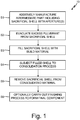
- FIG. 1 is a flow diagram illustrating steps of method 10, used to produce a high-temperature and/or high-strength component.
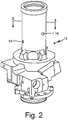
- FIG. 2 illustrates a sacrificial shell filled with a pulverant build material
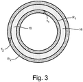
- FIG. 3 is a cross-sectional view of the elements shown in FIG. 2 .
- an intermediate part which in an exemplary embodiment is a sacrificial shell 12, is fabricated.
- Shell 12 can be formed using an additive manufacturing process, such as a powder bed fusion technique (e.g., selective laser melting, selective laser sintering, electron beam melting, etc.), or another process suitable for forming shell 12 from a metallic powder.
- a powder bed fusion technique e.g., selective laser melting, selective laser sintering, electron beam melting, etc.
- Exemplary metallic powders can include, for example, alloys of aluminum, nickel, and titanium.
- Shell 12 can be formed to include one or more apertures 14 fluidly connecting an inner portion 16 of shell 12 with the external environment.
- Shell 12 can further be formed to have a geometry complementary to that of the desired component, which in the embodiment shown in FIG. 2 is a ram air turbine (RAT) outer cylinder.
- RAT ram air turbine
- shell 12 can include a first region R 1 having a first thickness T 1 and a second region R 2 having a second thickness T 2 .
- first region R 1 having a first thickness T 1
- second region R 2 having a second thickness T 2 .
- the various regions in an alternative embodiment can be disposed along the same wall or surface.
- Additional varied thickness regions i.e., R 3 ...R N
- Shell 12 can be designed to have the minimum thickness required to withstand the consolidation process at step S3. In some embodiments, the minimum thickness of shell 12 can range from 75 ⁇ m to 120 ⁇ m, while in other embodiments, the minimum thickness can be as great as 1 mm. Greater and lesser shell thicknesses are contemplated herein.
- any excess powder trapped within inner portion 16 of shell 12 can be evacuated through apertures 14 by applying, for example an air stream or a vacuum to one or more of the apertures.
- shell 12 can be filled with an amount of pulverant material 18 that will form the completed component.
- Pulverant material 18 can be one or a mixture of a metallic, intermetallic, and/or metal matrix composite (MMC) materials. Exemplary materials can include "non-weldable" materials (i.e., materials susceptible to cracking during diffusion welding processes) such as Al 6061, Al 7075, IN 100, and high carbon steel, to name a few non-limiting examples.
- Pulverant material 18 can also include a weldable material, similar to what would be suitable to manufacture shell 12. The amount of pulverant material 18 added to shell 12 can depend on such factors as desired component geometry and density, as well as the consolidation process parameters, as is discussed in detail below.
- shell 12 can be vibrated to more evenly distribute and increase the apparent density of pulverant material 18.
- apertures 14 can also be sealed (after the addition of pulverant material 18) with a plug or other sealing means to form an air-tight shell 12.
- the sealing means can be permanent, removable, or a combination of the two throughout shell 12, depending on the application.
- additional pulverant material can be added, if desired. Successive fill and vibrate steps can be repeated until the desired pulverant apparent density and fill level is reached. In such cases, one or more removable sealing means may be advantageous in order to continue to add pulverant material 18, but also to retain the added material during vibration.
- shell 12 filled with pulverant material 18 can be subjected to a consolidation process performed at a high temperature and/or high pressure.
- exemplary processes can include hot isostatic pressing (HIP) and a lower temperature variation.
- HIP hot isostatic pressing
- filled shell 12 can be placed in a suitable HIP assembly (e.g., a high-temperature furnace within a pressure vessel) and subjected to elevated temperatures while an inert gas applies isostatic pressure to shell 12 from all sides for a predetermined time period.
- filled shell 12 can be preheated in a furnace and subsequently exposed to a relatively higher pressure (e.g., 2-3x higher) for a shorter duration as compared to the HIP process.
- a relatively higher pressure e.g., 2-3x higher
- Shell 12 can therefore be designed to include features that facilitate desired deformation, such as the varied shell thicknesses discussed above. Such features might additionally or alternatively include external stiffening elements (not shown).
- the microstructure of pulverant material 18 can also be specifically selected based on the consolidation process being used, and/or the desired density of the component. For example, pulverant material 18 containing mostly spherical particles can be more compressible than a dendritic pulverant material 18.
- shell 12 can, in an exemplary embodiment, be removed from the consolidated material 18 (i.e., the component).
- the removal of shell 12 can be carried out using a chemical process (e.g., etching) in which the component and shell are immersed in or otherwise exposed to a chemical solution for predetermined duration.
- the material used to form shell 12, the thickness of shell 12, and the chemical composition of the solution can all influence the time needed to achieve removal of shell 12.
- the component can additionally or alternatively undergo a mechanical removal process, such as cutting, milling, or grinding to remove shell 12.
- the component can undergo additional post-processing steps (e.g., polishing, coating, etc.) if necessary to achieve a desired surface finish, thermal, and/or mechanical properties.
- the component can be formed using only a partial shell structure, such that the intermediate part formed at step S1 includes a solid portion and a sacrificial shell.
- shell 12 of FIG. 2 can be limited to only the upper cylindrical portion of the desired RAT outer cylinder, while the lower base portion can be solidly formed using additive manufacturing.
- the solid base portion and upper shell portion can be formed during the same additive manufacture process.
- the shell portion would then be evacuated, filled with pulverant material 18, subjected to consolidation, then removed as described above regarding shell 12.
- Such a method may be desirable where one portion of a part requires fine or complex features better achieved through additive manufacturing, while another portion requires the microstructure and improved mechanical properties better achieved through a consolidation process.
- the disclosed methods can be used to fabricate components at or near 100 percent theoretical density and with improved mechanical properties due to the homogeneous microstructure. Because the sacrificial shells can be manufactured in a variety of shapes and sizes, the method can be used to form components for almost any industry. The method is particularly advantageous in aerospace applications, because many aerospace components are exposed to high operating temperatures and high cycle fatigue.
- a method of fabricating a near net shape component includes forming a sacrificial shell from a pulverant material using an additive manufacturing process, the shell having an aperture. The method further includes filling the shell with a second pulverant material, subjecting the filled shell to a consolidation process, and removing the shell from the consolidated second pulverant material.
- the method of the preceding paragraph can optionally include, additionally and/or alternatively, any one or more of the following features, configurations and/or additional components:
- the above method can further include evacuating any remaining first pulverant material from the shell prior to filling the shell with the second pulverant material.
- the first pulverant material can be evacuated through the aperture.
- filling the shell with the second pulverant material can include adding the second pulverant material through the aperture.
- Any of the above methods can further include sealing the aperture after filling the shell with the pulverant material.
- Any of the above methods can further include vibrating the shell to distribute the pulverant material within the shell.
- removing the shell can include a process selected from the group consisting of chemical etching, cutting, milling, grinding, and combinations thereof.
- the consolidation process can be an isostatic pressing process.
- the shell can have an inner surface geometry complementary to a component geometry.
- the first material can be different from the second material.
- the shell can further be formed having a first region with a first shell thickness, and a second region with a second shell thickness different from the first shell thickness.
- Any of the above methods can further include using the additive manufacturing process to form a solid component portion from the first pulverant material, the solid component portion being integral to the sacrificial shell.
- a system for fabricating a component includes a sacrificial shell formed from a first material and having an aperture, a second, pulverant material contained within the hollow shell, and means for consolidating the second material within the hollow shell.
- the system of the preceding paragraph can optionally include, additionally and/or alternatively, any one or more of the following features, configurations and/or additional components:
- the above system can further include means for removing the hollow shell from the consolidated second material.
- the means for consolidating the second material can be an isostatic pressing process.
- the first material can be different from the second material.
- the shell can include a first region with a first shell thickness, and a second region with a second shell thickness different from the first shell thickness.
- the shell can have an inner surface geometry complementary to a component geometry.
- Any of the above systems can further include a solid component portion formed from the first material and integral to the sacrificial shell.
Landscapes
- Engineering & Computer Science (AREA)
- Manufacturing & Machinery (AREA)
- Chemical & Material Sciences (AREA)
- Materials Engineering (AREA)
- Mechanical Engineering (AREA)
- Physics & Mathematics (AREA)
- Plasma & Fusion (AREA)
- Chemical Kinetics & Catalysis (AREA)
- General Chemical & Material Sciences (AREA)
- Powder Metallurgy (AREA)
Abstract
Description
- Powder bed fusion techniques can be used to create metallic components having complex geometries. However, the build powder can become contaminated during these processes due to impurities (e.g., O2, N2, Si, C) in particles ejected from the melt pool and end up with the feedstock. These impurities can be incorporated into the component during manufacturing and can result in reduced mechanical properties in the component. Such a result is undesirable particularly in components subject to high thermal and mechanical stresses.
- A method of fabricating a near net shape component includes forming a sacrificial shell from a pulverant material using an additive manufacturing process, the shell having an aperture. The method further includes filling the shell with a second pulverant material, subjecting the filled shell to a consolidation process, and removing the shell from the consolidated second pulverant material.
- A system for fabricating a component includes a sacrificial shell formed from a first material and having an aperture, a second, pulverant material contained within the hollow shell, and means for consolidating the second material within the hollow shell.
-
-
FIG. 1 is a flow chart illustrating steps of forming a component using a sacrificial shell. -
FIG. 2 is a simplified illustration showing elements of a system for fabricating the component, including the sacrificial shell filled with a pulverant build material. -
FIG. 3 is cross-sectional view of the shell and build material ofFIG. 2 . - A method of forming net shape (i.e., final) or near net shape (i.e., near final) components is disclosed herein. The method includes additively manufacturing a sacrificial shell with a geometry generally complementary to the desired component. The shell includes integral ports through which any contaminated or unused powder from the additive manufacturing process can be evacuated. A highly-pure pulverant material can be added to the shell through one or more of the ports, and the filled shell can subsequently undergo a high temperature and/or high pressure consolidation process, after which, the shell can be removed. The resulting component can include complex geometries, and also can be near 100% theoretical density with a generally homogenous microstructure.
-
FIG. 1 is a flow diagram illustrating steps ofmethod 10, used to produce a high-temperature and/or high-strength component.FIG. 2 illustrates a sacrificial shell filled with a pulverant build material, andFIG. 3 is a cross-sectional view of the elements shown inFIG. 2 . With continued reference toFIGS. 1-3 , at step S1, an intermediate part, which in an exemplary embodiment is asacrificial shell 12, is fabricated. Shell 12 can be formed using an additive manufacturing process, such as a powder bed fusion technique (e.g., selective laser melting, selective laser sintering, electron beam melting, etc.), or another process suitable for formingshell 12 from a metallic powder. Exemplary metallic powders can include, for example, alloys of aluminum, nickel, and titanium. Shell 12 can be formed to include one ormore apertures 14 fluidly connecting aninner portion 16 ofshell 12 with the external environment.Shell 12 can further be formed to have a geometry complementary to that of the desired component, which in the embodiment shown inFIG. 2 is a ram air turbine (RAT) outer cylinder. - As shown in
FIG. 3 ,shell 12 can include a first region R1 having a first thickness T1 and a second region R2 having a second thickness T2. Although shown as separate, concentric circles, the various regions in an alternative embodiment can be disposed along the same wall or surface. In someembodiments shell 12 can be formed with a uniform thickness such that T1 = T2, however, in alternative embodiments, T1 ≠ T2 (e.g., T2 is greater than T1). Such an embodiment can be advantageous to accommodate shell deformation during the consolidation process, as is discussed in detail below. Additional varied thickness regions (i.e., R3...RN) can be included as necessary to facilitate component fabrication. Shell 12 can be designed to have the minimum thickness required to withstand the consolidation process at step S3. In some embodiments, the minimum thickness ofshell 12 can range from 75 µm to 120 µm, while in other embodiments, the minimum thickness can be as great as 1 mm. Greater and lesser shell thicknesses are contemplated herein. - At step S2, any excess powder trapped within
inner portion 16 ofshell 12 can be evacuated throughapertures 14 by applying, for example an air stream or a vacuum to one or more of the apertures. At step S3,shell 12 can be filled with an amount ofpulverant material 18 that will form the completed component.Pulverant material 18 can be one or a mixture of a metallic, intermetallic, and/or metal matrix composite (MMC) materials. Exemplary materials can include "non-weldable" materials (i.e., materials susceptible to cracking during diffusion welding processes) such as Al 6061, Al 7075, IN 100, and high carbon steel, to name a few non-limiting examples.Pulverant material 18 can also include a weldable material, similar to what would be suitable to manufactureshell 12. The amount ofpulverant material 18 added toshell 12 can depend on such factors as desired component geometry and density, as well as the consolidation process parameters, as is discussed in detail below. - Once filled with the desired amount of
pulverant material 18,shell 12 can be vibrated to more evenly distribute and increase the apparent density ofpulverant material 18. In an exemplary embodiment,apertures 14 can also be sealed (after the addition of pulverant material 18) with a plug or other sealing means to form an air-tight shell 12. The sealing means can be permanent, removable, or a combination of the two throughoutshell 12, depending on the application. In some cases, after vibratingshell 12 containing an amount ofpulverant material 18, additional pulverant material can be added, if desired. Successive fill and vibrate steps can be repeated until the desired pulverant apparent density and fill level is reached. In such cases, one or more removable sealing means may be advantageous in order to continue to addpulverant material 18, but also to retain the added material during vibration. - At step S4,
shell 12 filled withpulverant material 18 can be subjected to a consolidation process performed at a high temperature and/or high pressure. Exemplary processes can include hot isostatic pressing (HIP) and a lower temperature variation. For the HIP process, filledshell 12 can be placed in a suitable HIP assembly (e.g., a high-temperature furnace within a pressure vessel) and subjected to elevated temperatures while an inert gas applies isostatic pressure to shell 12 from all sides for a predetermined time period. Alternatively, filledshell 12 can be preheated in a furnace and subsequently exposed to a relatively higher pressure (e.g., 2-3x higher) for a shorter duration as compared to the HIP process. The latter process can be advantageous for high-volume production, because the consolidation can occur in an open-air environment, and because the process generally takes less time to carry out. - During the consolidation process, exposure to high temperatures and pressure can cause
shell 12 to deform as thepulverant material 18 contained inside densifies.Shell 12 can therefore be designed to include features that facilitate desired deformation, such as the varied shell thicknesses discussed above. Such features might additionally or alternatively include external stiffening elements (not shown). The microstructure ofpulverant material 18 can also be specifically selected based on the consolidation process being used, and/or the desired density of the component. For example,pulverant material 18 containing mostly spherical particles can be more compressible than a dendriticpulverant material 18. - At step S5,
shell 12 can, in an exemplary embodiment, be removed from the consolidated material 18 (i.e., the component). The removal ofshell 12 can be carried out using a chemical process (e.g., etching) in which the component and shell are immersed in or otherwise exposed to a chemical solution for predetermined duration. The material used to formshell 12, the thickness ofshell 12, and the chemical composition of the solution can all influence the time needed to achieve removal ofshell 12. The component can additionally or alternatively undergo a mechanical removal process, such as cutting, milling, or grinding to removeshell 12. At step S6, the component can undergo additional post-processing steps (e.g., polishing, coating, etc.) if necessary to achieve a desired surface finish, thermal, and/or mechanical properties. - In an alternative embodiment, the component can be formed using only a partial shell structure, such that the intermediate part formed at step S1 includes a solid portion and a sacrificial shell. For example,
shell 12 ofFIG. 2 can be limited to only the upper cylindrical portion of the desired RAT outer cylinder, while the lower base portion can be solidly formed using additive manufacturing. In operation, the solid base portion and upper shell portion can be formed during the same additive manufacture process. The shell portion would then be evacuated, filled withpulverant material 18, subjected to consolidation, then removed as described above regardingshell 12. Such a method may be desirable where one portion of a part requires fine or complex features better achieved through additive manufacturing, while another portion requires the microstructure and improved mechanical properties better achieved through a consolidation process. - The disclosed methods can be used to fabricate components at or near 100 percent theoretical density and with improved mechanical properties due to the homogeneous microstructure. Because the sacrificial shells can be manufactured in a variety of shapes and sizes, the method can be used to form components for almost any industry. The method is particularly advantageous in aerospace applications, because many aerospace components are exposed to high operating temperatures and high cycle fatigue.
- The following are non-exclusive descriptions of possible embodiments of the present invention.
- A method of fabricating a near net shape component includes forming a sacrificial shell from a pulverant material using an additive manufacturing process, the shell having an aperture. The method further includes filling the shell with a second pulverant material, subjecting the filled shell to a consolidation process, and removing the shell from the consolidated second pulverant material.
- The method of the preceding paragraph can optionally include, additionally and/or alternatively, any one or more of the following features, configurations and/or additional components:
- The above method can further include evacuating any remaining first pulverant material from the shell prior to filling the shell with the second pulverant material.
- In any of the above methods, the first pulverant material can be evacuated through the aperture.
- In any of the above methods, filling the shell with the second pulverant material can include adding the second pulverant material through the aperture.
- Any of the above methods can further include sealing the aperture after filling the shell with the pulverant material.
- Any of the above methods can further include vibrating the shell to distribute the pulverant material within the shell.
- In any of the above methods, removing the shell can include a process selected from the group consisting of chemical etching, cutting, milling, grinding, and combinations thereof.
- In any of the above methods, the consolidation process can be an isostatic pressing process.
- In any of the above methods, the shell can have an inner surface geometry complementary to a component geometry.
- In any of the above methods, the first material can be different from the second material.
- In any of the above methods, the shell can further be formed having a first region with a first shell thickness, and a second region with a second shell thickness different from the first shell thickness.
- Any of the above methods can further include using the additive manufacturing process to form a solid component portion from the first pulverant material, the solid component portion being integral to the sacrificial shell.
- A system for fabricating a component includes a sacrificial shell formed from a first material and having an aperture, a second, pulverant material contained within the hollow shell, and means for consolidating the second material within the hollow shell.
- The system of the preceding paragraph can optionally include, additionally and/or alternatively, any one or more of the following features, configurations and/or additional components:
- The above system can further include means for removing the hollow shell from the consolidated second material.
- In any of the above systems, the means for consolidating the second material can be an isostatic pressing process.
- In any of the above systems, the first material can be different from the second material.
- In any of the above systems, the shell can include a first region with a first shell thickness, and a second region with a second shell thickness different from the first shell thickness.
- In any of the above systems, the shell can have an inner surface geometry complementary to a component geometry.
- Any of the above systems can further include a solid component portion formed from the first material and integral to the sacrificial shell.
- While the invention has been described with reference to an exemplary embodiment(s), it will be understood by those skilled in the art that various changes may be made and equivalents may be substituted for elements thereof without departing from the scope of the invention. In addition, many modifications may be made to adapt a particular situation or material to the teachings of the invention without departing from the essential scope thereof. Therefore, it is intended that the invention not be limited to the particular embodiment(s) disclosed, but that the invention will include all embodiments falling within the scope of the appended claims.
Claims (15)
- A method of fabricating a near net shape component, the method comprising:forming a sacrificial shell (12) from a first pulverant material (18) using an additive manufacturing process, the shell comprising an aperture (14);filling the shell with a second pulverant material;subjecting the filled shell to a consolidation process; andremoving the shell from the consolidated second pulverant material.
- The method of claim 1 and further comprising: evacuating any remaining first pulverant material from the shell prior to filling the shell with the second pulverant material.
- The method of claim 2, wherein the first pulverant material is evacuated through the aperture.
- The method of any preceding claim, wherein filling the shell with the second pulverant material comprises adding the second pulverant material through the aperture.
- The method of claim 4 and further comprising: sealing the aperture after filling the shell with the pulverant material, and preferably further comprising: vibrating the shell to distribute the pulverant material within the shell.
- The method of any preceding claim, wherein removing the shell comprises a process selected from the group consisting of chemical etching, cutting, milling, grinding, and combinations thereof.
- The method of any preceding claim, wherein the consolidation process is an isostatic pressing process.
- The method of any preceding claim, wherein the shell has an inner surface geometry complementary to a component geometry.
- The method of any preceding claim, wherein the first material is different from the second material.
- The method of any preceding claim, wherein the shell is further formed having a first region with a first shell thickness, and a second region with a second shell thickness different from the first shell thickness.
- The method of any preceding claim, and further comprising: using the additive manufacturing process to form a solid component portion from the first pulverant material, the solid component portion being integral to the sacrificial shell.
- The method of any preceding claim, wherein the additive manufacturing process is a powder bed fusion process.
- A system for fabricating a component, the system comprising:a sacrificial shell (12) formed from a first material and comprising an aperture (14);a second material contained within the hollow shell, the second material being a pulverant material (18); andmeans for consolidating the second material within the hollow shell.
- The system of claim 14, wherein the shell comprises a first region with a first shell thickness, and a second region with a second shell thickness different from the first shell thickness, and/or wherein the shell has an inner surface geometry complementary to a component geometry.
- The system of claim 13 or 14 and further comprising: a solid component portion formed from the first material and integral to the sacrificial shell.
Applications Claiming Priority (1)
| Application Number | Priority Date | Filing Date | Title |
|---|---|---|---|
| US16/176,730 US11498125B2 (en) | 2018-10-31 | 2018-10-31 | Method for fabricating components using hybrid additive manufacturing and consolidation process |
Publications (2)
| Publication Number | Publication Date |
|---|---|
| EP3646970A1 true EP3646970A1 (en) | 2020-05-06 |
| EP3646970B1 EP3646970B1 (en) | 2024-08-21 |
Family
ID=68424614
Family Applications (1)
| Application Number | Title | Priority Date | Filing Date |
|---|---|---|---|
| EP19206218.0A Active EP3646970B1 (en) | 2018-10-31 | 2019-10-30 | Method for fabricating components using hybrid additive manufacturing and consolidation process |
Country Status (2)
| Country | Link |
|---|---|
| US (2) | US11498125B2 (en) |
| EP (1) | EP3646970B1 (en) |
Citations (5)
| Publication number | Priority date | Publication date | Assignee | Title |
|---|---|---|---|---|
| EP2551040A1 (en) * | 2011-07-25 | 2013-01-30 | EADS Deutschland GmbH | Method of manufacturing a component by hot isostatic pressing |
| WO2015057761A1 (en) * | 2013-10-17 | 2015-04-23 | The Exone Company | Three-dimensional printed hot isostatic pressing containers and processes for making same |
| EP3064295A1 (en) * | 2015-03-05 | 2016-09-07 | General Electric Company | Process for producing an article |
| EP3072611A2 (en) * | 2015-03-26 | 2016-09-28 | Honeywell International Inc. | Net-shape or near-net shape powder metal components and methods for producing the same |
| US20170291221A1 (en) * | 2016-04-07 | 2017-10-12 | Great Lakes Images & Engineering, Llc | Using thin-walled containers in powder metallurgy |
Family Cites Families (3)
| Publication number | Priority date | Publication date | Assignee | Title |
|---|---|---|---|---|
| US5640667A (en) * | 1995-11-27 | 1997-06-17 | Board Of Regents, The University Of Texas System | Laser-directed fabrication of full-density metal articles using hot isostatic processing |
| GB201416223D0 (en) * | 2014-09-15 | 2014-10-29 | Rolls Royce Plc | Manufacturing method |
| US11014292B2 (en) * | 2018-09-17 | 2021-05-25 | Caterpillar Inc. | Hybrid methods of additive manufacturing |
-
2018
- 2018-10-31 US US16/176,730 patent/US11498125B2/en active Active
-
2019
- 2019-10-30 EP EP19206218.0A patent/EP3646970B1/en active Active
-
2022
- 2022-10-13 US US18/046,250 patent/US20230127804A1/en not_active Abandoned
Patent Citations (5)
| Publication number | Priority date | Publication date | Assignee | Title |
|---|---|---|---|---|
| EP2551040A1 (en) * | 2011-07-25 | 2013-01-30 | EADS Deutschland GmbH | Method of manufacturing a component by hot isostatic pressing |
| WO2015057761A1 (en) * | 2013-10-17 | 2015-04-23 | The Exone Company | Three-dimensional printed hot isostatic pressing containers and processes for making same |
| EP3064295A1 (en) * | 2015-03-05 | 2016-09-07 | General Electric Company | Process for producing an article |
| EP3072611A2 (en) * | 2015-03-26 | 2016-09-28 | Honeywell International Inc. | Net-shape or near-net shape powder metal components and methods for producing the same |
| US20170291221A1 (en) * | 2016-04-07 | 2017-10-12 | Great Lakes Images & Engineering, Llc | Using thin-walled containers in powder metallurgy |
Also Published As
| Publication number | Publication date |
|---|---|
| US20230127804A1 (en) | 2023-04-27 |
| EP3646970B1 (en) | 2024-08-21 |
| US11498125B2 (en) | 2022-11-15 |
| US20200130059A1 (en) | 2020-04-30 |
Similar Documents
| Publication | Publication Date | Title |
|---|---|---|
| JP6804205B2 (en) | Manufacturing method of goods | |
| EP2995398B1 (en) | Article manufacturing method from powders | |
| US11014292B2 (en) | Hybrid methods of additive manufacturing | |
| JP6553514B2 (en) | Method for additive fabrication of parts by selective melting or selective sintering of tightly optimized powder beds using high energy beams | |
| US12534782B2 (en) | Process for manufacturing an aluminum alloy part | |
| Manfredi et al. | Laser powder bed fusion of aluminum alloys | |
| EP2551040A1 (en) | Method of manufacturing a component by hot isostatic pressing | |
| CN101918609B (en) | Method for making parts with an insert made of a metal-matrix composite material | |
| EP3033189B1 (en) | Hip can manufacture process | |
| EP2785482B1 (en) | Endplate for hot isostatic pressing canister, hot isostatic pressing canister, and hot isostatic pressing method | |
| US20130039799A1 (en) | Method of Making Near-Net Shapes From Powdered Metals | |
| US20160243621A1 (en) | Three-Dimensional Printed Hot Isostatic Pressing Containers and Processes for Making Same | |
| US4104782A (en) | Method for consolidating precision shapes | |
| WO2016030654A1 (en) | A mould for use in a hot isostatic press | |
| EP2340905B1 (en) | A method of manufacturing a component | |
| US6939508B2 (en) | Method of manufacturing net-shaped bimetallic parts | |
| EP3632657B1 (en) | Manufacturing method | |
| US20230127804A1 (en) | Method for fabricating components using hybrid additive manufacturing and consolidation process | |
| GB2283042A (en) | Method for fabricating long-fibre-reinforced components, e.g. turbine blades | |
| CN118808670A (en) | A hot isostatic pressing additive manufacturing composite preparation method for titanium alloy components | |
| HK1223887B (en) | Hip can manufacture process |
Legal Events
| Date | Code | Title | Description |
|---|---|---|---|
| PUAI | Public reference made under article 153(3) epc to a published international application that has entered the european phase |
Free format text: ORIGINAL CODE: 0009012 |
|
| STAA | Information on the status of an ep patent application or granted ep patent |
Free format text: STATUS: THE APPLICATION HAS BEEN PUBLISHED |
|
| AK | Designated contracting states |
Kind code of ref document: A1 Designated state(s): AL AT BE BG CH CY CZ DE DK EE ES FI FR GB GR HR HU IE IS IT LI LT LU LV MC MK MT NL NO PL PT RO RS SE SI SK SM TR |
|
| AX | Request for extension of the european patent |
Extension state: BA ME |
|
| STAA | Information on the status of an ep patent application or granted ep patent |
Free format text: STATUS: REQUEST FOR EXAMINATION WAS MADE |
|
| 17P | Request for examination filed |
Effective date: 20201106 |
|
| RBV | Designated contracting states (corrected) |
Designated state(s): AL AT BE BG CH CY CZ DE DK EE ES FI FR GB GR HR HU IE IS IT LI LT LU LV MC MK MT NL NO PL PT RO RS SE SI SK SM TR |
|
| STAA | Information on the status of an ep patent application or granted ep patent |
Free format text: STATUS: EXAMINATION IS IN PROGRESS |
|
| 17Q | First examination report despatched |
Effective date: 20210122 |
|
| REG | Reference to a national code |
Ref country code: DE Ref legal event code: R079 Free format text: PREVIOUS MAIN CLASS: B22F0003105000 Ipc: B22F0010280000 Ref country code: DE Ref legal event code: R079 Ref document number: 602019057305 Country of ref document: DE Free format text: PREVIOUS MAIN CLASS: B22F0003105000 Ipc: B22F0010280000 |
|
| GRAP | Despatch of communication of intention to grant a patent |
Free format text: ORIGINAL CODE: EPIDOSNIGR1 |
|
| STAA | Information on the status of an ep patent application or granted ep patent |
Free format text: STATUS: GRANT OF PATENT IS INTENDED |
|
| INTG | Intention to grant announced |
Effective date: 20240322 |
|
| RIC1 | Information provided on ipc code assigned before grant |
Ipc: B22F 3/15 20060101ALI20240312BHEP Ipc: B22F 10/68 20210101ALI20240312BHEP Ipc: B22F 10/66 20210101ALI20240312BHEP Ipc: B22F 10/62 20210101ALI20240312BHEP Ipc: B22F 10/28 20210101AFI20240312BHEP |
|
| GRAS | Grant fee paid |
Free format text: ORIGINAL CODE: EPIDOSNIGR3 |
|
| GRAA | (expected) grant |
Free format text: ORIGINAL CODE: 0009210 |
|
| STAA | Information on the status of an ep patent application or granted ep patent |
Free format text: STATUS: THE PATENT HAS BEEN GRANTED |
|
| AK | Designated contracting states |
Kind code of ref document: B1 Designated state(s): AL AT BE BG CH CY CZ DE DK EE ES FI FR GB GR HR HU IE IS IT LI LT LU LV MC MK MT NL NO PL PT RO RS SE SI SK SM TR |
|
| REG | Reference to a national code |
Ref country code: GB Ref legal event code: FG4D |
|
| REG | Reference to a national code |
Ref country code: CH Ref legal event code: EP |
|
| REG | Reference to a national code |
Ref country code: DE Ref legal event code: R096 Ref document number: 602019057305 Country of ref document: DE |
|
| REG | Reference to a national code |
Ref country code: IE Ref legal event code: FG4D |
|
| REG | Reference to a national code |
Ref country code: LT Ref legal event code: MG9D |
|
| REG | Reference to a national code |
Ref country code: NL Ref legal event code: MP Effective date: 20240821 |
|
| PG25 | Lapsed in a contracting state [announced via postgrant information from national office to epo] |
Ref country code: NO Free format text: LAPSE BECAUSE OF FAILURE TO SUBMIT A TRANSLATION OF THE DESCRIPTION OR TO PAY THE FEE WITHIN THE PRESCRIBED TIME-LIMIT Effective date: 20241121 |
|
| REG | Reference to a national code |
Ref country code: AT Ref legal event code: MK05 Ref document number: 1715055 Country of ref document: AT Kind code of ref document: T Effective date: 20240821 |
|
| PG25 | Lapsed in a contracting state [announced via postgrant information from national office to epo] |
Ref country code: NL Free format text: LAPSE BECAUSE OF FAILURE TO SUBMIT A TRANSLATION OF THE DESCRIPTION OR TO PAY THE FEE WITHIN THE PRESCRIBED TIME-LIMIT Effective date: 20240821 Ref country code: PT Free format text: LAPSE BECAUSE OF FAILURE TO SUBMIT A TRANSLATION OF THE DESCRIPTION OR TO PAY THE FEE WITHIN THE PRESCRIBED TIME-LIMIT Effective date: 20241223 Ref country code: PL Free format text: LAPSE BECAUSE OF FAILURE TO SUBMIT A TRANSLATION OF THE DESCRIPTION OR TO PAY THE FEE WITHIN THE PRESCRIBED TIME-LIMIT Effective date: 20240821 Ref country code: FI Free format text: LAPSE BECAUSE OF FAILURE TO SUBMIT A TRANSLATION OF THE DESCRIPTION OR TO PAY THE FEE WITHIN THE PRESCRIBED TIME-LIMIT Effective date: 20240821 Ref country code: GR Free format text: LAPSE BECAUSE OF FAILURE TO SUBMIT A TRANSLATION OF THE DESCRIPTION OR TO PAY THE FEE WITHIN THE PRESCRIBED TIME-LIMIT Effective date: 20241122 |
|
| PG25 | Lapsed in a contracting state [announced via postgrant information from national office to epo] |
Ref country code: BG Free format text: LAPSE BECAUSE OF FAILURE TO SUBMIT A TRANSLATION OF THE DESCRIPTION OR TO PAY THE FEE WITHIN THE PRESCRIBED TIME-LIMIT Effective date: 20240821 |
|
| PG25 | Lapsed in a contracting state [announced via postgrant information from national office to epo] |
Ref country code: LV Free format text: LAPSE BECAUSE OF FAILURE TO SUBMIT A TRANSLATION OF THE DESCRIPTION OR TO PAY THE FEE WITHIN THE PRESCRIBED TIME-LIMIT Effective date: 20240821 |
|
| PG25 | Lapsed in a contracting state [announced via postgrant information from national office to epo] |
Ref country code: AT Free format text: LAPSE BECAUSE OF FAILURE TO SUBMIT A TRANSLATION OF THE DESCRIPTION OR TO PAY THE FEE WITHIN THE PRESCRIBED TIME-LIMIT Effective date: 20240821 Ref country code: IS Free format text: LAPSE BECAUSE OF FAILURE TO SUBMIT A TRANSLATION OF THE DESCRIPTION OR TO PAY THE FEE WITHIN THE PRESCRIBED TIME-LIMIT Effective date: 20241221 |
|
| PG25 | Lapsed in a contracting state [announced via postgrant information from national office to epo] |
Ref country code: HR Free format text: LAPSE BECAUSE OF FAILURE TO SUBMIT A TRANSLATION OF THE DESCRIPTION OR TO PAY THE FEE WITHIN THE PRESCRIBED TIME-LIMIT Effective date: 20240821 |
|
| PG25 | Lapsed in a contracting state [announced via postgrant information from national office to epo] |
Ref country code: ES Free format text: LAPSE BECAUSE OF FAILURE TO SUBMIT A TRANSLATION OF THE DESCRIPTION OR TO PAY THE FEE WITHIN THE PRESCRIBED TIME-LIMIT Effective date: 20240821 Ref country code: RS Free format text: LAPSE BECAUSE OF FAILURE TO SUBMIT A TRANSLATION OF THE DESCRIPTION OR TO PAY THE FEE WITHIN THE PRESCRIBED TIME-LIMIT Effective date: 20241121 |
|
| PG25 | Lapsed in a contracting state [announced via postgrant information from national office to epo] |
Ref country code: RS Free format text: LAPSE BECAUSE OF FAILURE TO SUBMIT A TRANSLATION OF THE DESCRIPTION OR TO PAY THE FEE WITHIN THE PRESCRIBED TIME-LIMIT Effective date: 20241121 Ref country code: PT Free format text: LAPSE BECAUSE OF FAILURE TO SUBMIT A TRANSLATION OF THE DESCRIPTION OR TO PAY THE FEE WITHIN THE PRESCRIBED TIME-LIMIT Effective date: 20241223 Ref country code: PL Free format text: LAPSE BECAUSE OF FAILURE TO SUBMIT A TRANSLATION OF THE DESCRIPTION OR TO PAY THE FEE WITHIN THE PRESCRIBED TIME-LIMIT Effective date: 20240821 Ref country code: NO Free format text: LAPSE BECAUSE OF FAILURE TO SUBMIT A TRANSLATION OF THE DESCRIPTION OR TO PAY THE FEE WITHIN THE PRESCRIBED TIME-LIMIT Effective date: 20241121 Ref country code: NL Free format text: LAPSE BECAUSE OF FAILURE TO SUBMIT A TRANSLATION OF THE DESCRIPTION OR TO PAY THE FEE WITHIN THE PRESCRIBED TIME-LIMIT Effective date: 20240821 Ref country code: LV Free format text: LAPSE BECAUSE OF FAILURE TO SUBMIT A TRANSLATION OF THE DESCRIPTION OR TO PAY THE FEE WITHIN THE PRESCRIBED TIME-LIMIT Effective date: 20240821 Ref country code: IS Free format text: LAPSE BECAUSE OF FAILURE TO SUBMIT A TRANSLATION OF THE DESCRIPTION OR TO PAY THE FEE WITHIN THE PRESCRIBED TIME-LIMIT Effective date: 20241221 Ref country code: HR Free format text: LAPSE BECAUSE OF FAILURE TO SUBMIT A TRANSLATION OF THE DESCRIPTION OR TO PAY THE FEE WITHIN THE PRESCRIBED TIME-LIMIT Effective date: 20240821 Ref country code: GR Free format text: LAPSE BECAUSE OF FAILURE TO SUBMIT A TRANSLATION OF THE DESCRIPTION OR TO PAY THE FEE WITHIN THE PRESCRIBED TIME-LIMIT Effective date: 20241122 Ref country code: FI Free format text: LAPSE BECAUSE OF FAILURE TO SUBMIT A TRANSLATION OF THE DESCRIPTION OR TO PAY THE FEE WITHIN THE PRESCRIBED TIME-LIMIT Effective date: 20240821 Ref country code: ES Free format text: LAPSE BECAUSE OF FAILURE TO SUBMIT A TRANSLATION OF THE DESCRIPTION OR TO PAY THE FEE WITHIN THE PRESCRIBED TIME-LIMIT Effective date: 20240821 Ref country code: BG Free format text: LAPSE BECAUSE OF FAILURE TO SUBMIT A TRANSLATION OF THE DESCRIPTION OR TO PAY THE FEE WITHIN THE PRESCRIBED TIME-LIMIT Effective date: 20240821 Ref country code: AT Free format text: LAPSE BECAUSE OF FAILURE TO SUBMIT A TRANSLATION OF THE DESCRIPTION OR TO PAY THE FEE WITHIN THE PRESCRIBED TIME-LIMIT Effective date: 20240821 |
|
| PG25 | Lapsed in a contracting state [announced via postgrant information from national office to epo] |
Ref country code: DK Free format text: LAPSE BECAUSE OF FAILURE TO SUBMIT A TRANSLATION OF THE DESCRIPTION OR TO PAY THE FEE WITHIN THE PRESCRIBED TIME-LIMIT Effective date: 20240821 Ref country code: SM Free format text: LAPSE BECAUSE OF FAILURE TO SUBMIT A TRANSLATION OF THE DESCRIPTION OR TO PAY THE FEE WITHIN THE PRESCRIBED TIME-LIMIT Effective date: 20240821 Ref country code: RO Free format text: LAPSE BECAUSE OF FAILURE TO SUBMIT A TRANSLATION OF THE DESCRIPTION OR TO PAY THE FEE WITHIN THE PRESCRIBED TIME-LIMIT Effective date: 20240821 |
|
| PG25 | Lapsed in a contracting state [announced via postgrant information from national office to epo] |
Ref country code: EE Free format text: LAPSE BECAUSE OF FAILURE TO SUBMIT A TRANSLATION OF THE DESCRIPTION OR TO PAY THE FEE WITHIN THE PRESCRIBED TIME-LIMIT Effective date: 20240821 |
|
| PG25 | Lapsed in a contracting state [announced via postgrant information from national office to epo] |
Ref country code: CZ Free format text: LAPSE BECAUSE OF FAILURE TO SUBMIT A TRANSLATION OF THE DESCRIPTION OR TO PAY THE FEE WITHIN THE PRESCRIBED TIME-LIMIT Effective date: 20240821 |
|
| PG25 | Lapsed in a contracting state [announced via postgrant information from national office to epo] |
Ref country code: IT Free format text: LAPSE BECAUSE OF FAILURE TO SUBMIT A TRANSLATION OF THE DESCRIPTION OR TO PAY THE FEE WITHIN THE PRESCRIBED TIME-LIMIT Effective date: 20240821 Ref country code: SK Free format text: LAPSE BECAUSE OF FAILURE TO SUBMIT A TRANSLATION OF THE DESCRIPTION OR TO PAY THE FEE WITHIN THE PRESCRIBED TIME-LIMIT Effective date: 20240821 |
|
| REG | Reference to a national code |
Ref country code: DE Ref legal event code: R097 Ref document number: 602019057305 Country of ref document: DE |
|
| REG | Reference to a national code |
Ref country code: CH Ref legal event code: PL |
|
| PLBE | No opposition filed within time limit |
Free format text: ORIGINAL CODE: 0009261 |
|
| STAA | Information on the status of an ep patent application or granted ep patent |
Free format text: STATUS: NO OPPOSITION FILED WITHIN TIME LIMIT |
|
| PG25 | Lapsed in a contracting state [announced via postgrant information from national office to epo] |
Ref country code: MC Free format text: LAPSE BECAUSE OF FAILURE TO SUBMIT A TRANSLATION OF THE DESCRIPTION OR TO PAY THE FEE WITHIN THE PRESCRIBED TIME-LIMIT Effective date: 20240821 |
|
| PG25 | Lapsed in a contracting state [announced via postgrant information from national office to epo] |
Ref country code: LU Free format text: LAPSE BECAUSE OF NON-PAYMENT OF DUE FEES Effective date: 20241030 Ref country code: BE Free format text: LAPSE BECAUSE OF NON-PAYMENT OF DUE FEES Effective date: 20241031 |
|
| PG25 | Lapsed in a contracting state [announced via postgrant information from national office to epo] |
Ref country code: CH Free format text: LAPSE BECAUSE OF NON-PAYMENT OF DUE FEES Effective date: 20241031 |
|
| 26N | No opposition filed |
Effective date: 20250522 |
|
| REG | Reference to a national code |
Ref country code: BE Ref legal event code: MM Effective date: 20241031 |
|
| PG25 | Lapsed in a contracting state [announced via postgrant information from national office to epo] |
Ref country code: SE Free format text: LAPSE BECAUSE OF FAILURE TO SUBMIT A TRANSLATION OF THE DESCRIPTION OR TO PAY THE FEE WITHIN THE PRESCRIBED TIME-LIMIT Effective date: 20240821 |
|
| PGFP | Annual fee paid to national office [announced via postgrant information from national office to epo] |
Ref country code: GB Payment date: 20250923 Year of fee payment: 7 |
|
| PGFP | Annual fee paid to national office [announced via postgrant information from national office to epo] |
Ref country code: FR Payment date: 20250923 Year of fee payment: 7 |
|
| PG25 | Lapsed in a contracting state [announced via postgrant information from national office to epo] |
Ref country code: IE Free format text: LAPSE BECAUSE OF NON-PAYMENT OF DUE FEES Effective date: 20241030 |
|
| PGFP | Annual fee paid to national office [announced via postgrant information from national office to epo] |
Ref country code: DE Payment date: 20250923 Year of fee payment: 7 |
|
| PG25 | Lapsed in a contracting state [announced via postgrant information from national office to epo] |
Ref country code: HU Free format text: LAPSE BECAUSE OF FAILURE TO SUBMIT A TRANSLATION OF THE DESCRIPTION OR TO PAY THE FEE WITHIN THE PRESCRIBED TIME-LIMIT; INVALID AB INITIO Effective date: 20191030 |
|
| PG25 | Lapsed in a contracting state [announced via postgrant information from national office to epo] |
Ref country code: CY Free format text: LAPSE BECAUSE OF FAILURE TO SUBMIT A TRANSLATION OF THE DESCRIPTION OR TO PAY THE FEE WITHIN THE PRESCRIBED TIME-LIMIT; INVALID AB INITIO Effective date: 20191030 |