EP3646771A1 - Surgical imaging system and signal processing device for surgical image - Google Patents
Surgical imaging system and signal processing device for surgical image Download PDFInfo
- Publication number
- EP3646771A1 EP3646771A1 EP18822911.6A EP18822911A EP3646771A1 EP 3646771 A1 EP3646771 A1 EP 3646771A1 EP 18822911 A EP18822911 A EP 18822911A EP 3646771 A1 EP3646771 A1 EP 3646771A1
- Authority
- EP
- European Patent Office
- Prior art keywords
- image
- image sensor
- imaging system
- surgical
- visible light
- Prior art date
- Legal status (The legal status is an assumption and is not a legal conclusion. Google has not performed a legal analysis and makes no representation as to the accuracy of the status listed.)
- Withdrawn
Links
Images





Classifications
-
- A—HUMAN NECESSITIES
- A61—MEDICAL OR VETERINARY SCIENCE; HYGIENE
- A61B—DIAGNOSIS; SURGERY; IDENTIFICATION
- A61B1/00—Instruments for performing medical examinations of the interior of cavities or tubes of the body by visual or photographical inspection, e.g. endoscopes; Illuminating arrangements therefor
- A61B1/00163—Optical arrangements
- A61B1/00186—Optical arrangements with imaging filters
-
- A—HUMAN NECESSITIES
- A61—MEDICAL OR VETERINARY SCIENCE; HYGIENE
- A61B—DIAGNOSIS; SURGERY; IDENTIFICATION
- A61B1/00—Instruments for performing medical examinations of the interior of cavities or tubes of the body by visual or photographical inspection, e.g. endoscopes; Illuminating arrangements therefor
- A61B1/00002—Operational features of endoscopes
- A61B1/00004—Operational features of endoscopes characterised by electronic signal processing
- A61B1/00009—Operational features of endoscopes characterised by electronic signal processing of image signals during a use of endoscope
- A61B1/000094—Operational features of endoscopes characterised by electronic signal processing of image signals during a use of endoscope extracting biological structures
-
- A—HUMAN NECESSITIES
- A61—MEDICAL OR VETERINARY SCIENCE; HYGIENE
- A61B—DIAGNOSIS; SURGERY; IDENTIFICATION
- A61B1/00—Instruments for performing medical examinations of the interior of cavities or tubes of the body by visual or photographical inspection, e.g. endoscopes; Illuminating arrangements therefor
- A61B1/04—Instruments for performing medical examinations of the interior of cavities or tubes of the body by visual or photographical inspection, e.g. endoscopes; Illuminating arrangements therefor combined with photographic or television appliances
-
- A—HUMAN NECESSITIES
- A61—MEDICAL OR VETERINARY SCIENCE; HYGIENE
- A61B—DIAGNOSIS; SURGERY; IDENTIFICATION
- A61B1/00—Instruments for performing medical examinations of the interior of cavities or tubes of the body by visual or photographical inspection, e.g. endoscopes; Illuminating arrangements therefor
- A61B1/04—Instruments for performing medical examinations of the interior of cavities or tubes of the body by visual or photographical inspection, e.g. endoscopes; Illuminating arrangements therefor combined with photographic or television appliances
- A61B1/046—Instruments for performing medical examinations of the interior of cavities or tubes of the body by visual or photographical inspection, e.g. endoscopes; Illuminating arrangements therefor combined with photographic or television appliances for infrared imaging
-
- A—HUMAN NECESSITIES
- A61—MEDICAL OR VETERINARY SCIENCE; HYGIENE
- A61B—DIAGNOSIS; SURGERY; IDENTIFICATION
- A61B1/00—Instruments for performing medical examinations of the interior of cavities or tubes of the body by visual or photographical inspection, e.g. endoscopes; Illuminating arrangements therefor
- A61B1/04—Instruments for performing medical examinations of the interior of cavities or tubes of the body by visual or photographical inspection, e.g. endoscopes; Illuminating arrangements therefor combined with photographic or television appliances
- A61B1/05—Instruments for performing medical examinations of the interior of cavities or tubes of the body by visual or photographical inspection, e.g. endoscopes; Illuminating arrangements therefor combined with photographic or television appliances characterised by the image sensor, e.g. camera, being in the distal end portion
-
- A—HUMAN NECESSITIES
- A61—MEDICAL OR VETERINARY SCIENCE; HYGIENE
- A61B—DIAGNOSIS; SURGERY; IDENTIFICATION
- A61B1/00—Instruments for performing medical examinations of the interior of cavities or tubes of the body by visual or photographical inspection, e.g. endoscopes; Illuminating arrangements therefor
- A61B1/06—Instruments for performing medical examinations of the interior of cavities or tubes of the body by visual or photographical inspection, e.g. endoscopes; Illuminating arrangements therefor with illuminating arrangements
- A61B1/0646—Instruments for performing medical examinations of the interior of cavities or tubes of the body by visual or photographical inspection, e.g. endoscopes; Illuminating arrangements therefor with illuminating arrangements with illumination filters
-
- A—HUMAN NECESSITIES
- A61—MEDICAL OR VETERINARY SCIENCE; HYGIENE
- A61B—DIAGNOSIS; SURGERY; IDENTIFICATION
- A61B1/00—Instruments for performing medical examinations of the interior of cavities or tubes of the body by visual or photographical inspection, e.g. endoscopes; Illuminating arrangements therefor
- A61B1/06—Instruments for performing medical examinations of the interior of cavities or tubes of the body by visual or photographical inspection, e.g. endoscopes; Illuminating arrangements therefor with illuminating arrangements
- A61B1/0661—Endoscope light sources
-
- G—PHYSICS
- G02—OPTICS
- G02B—OPTICAL ELEMENTS, SYSTEMS OR APPARATUS
- G02B27/00—Optical systems or apparatus not provided for by any of the groups G02B1/00 - G02B26/00, G02B30/00
- G02B27/10—Beam splitting or combining systems
- G02B27/1006—Beam splitting or combining systems for splitting or combining different wavelengths
- G02B27/1013—Beam splitting or combining systems for splitting or combining different wavelengths for colour or multispectral image sensors, e.g. splitting an image into monochromatic image components on respective sensors
-
- G—PHYSICS
- G02—OPTICS
- G02B—OPTICAL ELEMENTS, SYSTEMS OR APPARATUS
- G02B27/00—Optical systems or apparatus not provided for by any of the groups G02B1/00 - G02B26/00, G02B30/00
- G02B27/10—Beam splitting or combining systems
- G02B27/12—Beam splitting or combining systems operating by refraction only
- G02B27/126—The splitting element being a prism or prismatic array, including systems based on total internal reflection
-
- G—PHYSICS
- G06—COMPUTING OR CALCULATING; COUNTING
- G06T—IMAGE DATA PROCESSING OR GENERATION, IN GENERAL
- G06T7/00—Image analysis
- G06T7/0002—Inspection of images, e.g. flaw detection
- G06T7/0012—Biomedical image inspection
-
- H—ELECTRICITY
- H04—ELECTRIC COMMUNICATION TECHNIQUE
- H04N—PICTORIAL COMMUNICATION, e.g. TELEVISION
- H04N23/00—Cameras or camera modules comprising electronic image sensors; Control thereof
- H04N23/10—Cameras or camera modules comprising electronic image sensors; Control thereof for generating image signals from different wavelengths
- H04N23/11—Cameras or camera modules comprising electronic image sensors; Control thereof for generating image signals from different wavelengths for generating image signals from visible and infrared light wavelengths
-
- H—ELECTRICITY
- H04—ELECTRIC COMMUNICATION TECHNIQUE
- H04N—PICTORIAL COMMUNICATION, e.g. TELEVISION
- H04N23/00—Cameras or camera modules comprising electronic image sensors; Control thereof
- H04N23/10—Cameras or camera modules comprising electronic image sensors; Control thereof for generating image signals from different wavelengths
- H04N23/13—Cameras or camera modules comprising electronic image sensors; Control thereof for generating image signals from different wavelengths with multiple sensors
-
- H—ELECTRICITY
- H04—ELECTRIC COMMUNICATION TECHNIQUE
- H04N—PICTORIAL COMMUNICATION, e.g. TELEVISION
- H04N23/00—Cameras or camera modules comprising electronic image sensors; Control thereof
- H04N23/60—Control of cameras or camera modules
-
- G—PHYSICS
- G06—COMPUTING OR CALCULATING; COUNTING
- G06T—IMAGE DATA PROCESSING OR GENERATION, IN GENERAL
- G06T2207/00—Indexing scheme for image analysis or image enhancement
- G06T2207/10—Image acquisition modality
- G06T2207/10024—Color image
-
- G—PHYSICS
- G06—COMPUTING OR CALCULATING; COUNTING
- G06T—IMAGE DATA PROCESSING OR GENERATION, IN GENERAL
- G06T2207/00—Indexing scheme for image analysis or image enhancement
- G06T2207/10—Image acquisition modality
- G06T2207/10048—Infrared image
-
- G—PHYSICS
- G06—COMPUTING OR CALCULATING; COUNTING
- G06T—IMAGE DATA PROCESSING OR GENERATION, IN GENERAL
- G06T2207/00—Indexing scheme for image analysis or image enhancement
- G06T2207/20—Special algorithmic details
- G06T2207/20024—Filtering details
-
- G—PHYSICS
- G06—COMPUTING OR CALCULATING; COUNTING
- G06T—IMAGE DATA PROCESSING OR GENERATION, IN GENERAL
- G06T2207/00—Indexing scheme for image analysis or image enhancement
- G06T2207/30—Subject of image; Context of image processing
- G06T2207/30004—Biomedical image processing
- G06T2207/30101—Blood vessel; Artery; Vein; Vascular
Definitions
- the present disclosure relates to a surgical imaging system and a signal processing device of a surgical image.
- Patent Document 1 discloses a configuration in which a Si-based CCD, a CMOS camera and the like are used as a first imaging means, and an InGaAs camera, a germanium camera, a vidicon camera and the like are used as a second imaging means, the second imaging means not having sensitivity to a wavelength of visible light.
- Patent Document 1 Japanese Patent Application Laid-Open No. 2013-162978
- an image sensor using indium gallium arsenide generally has lower resolution than resolution of a silicon-based image sensor. For this reason, in the technology disclosed in Patent Document described above, for example, in a case of observing a surgical site, it is difficult to obtain a high-resolution image such as a visible light image because of low resolution of the InGaAs camera.
- the present disclosure provides a surgical imaging system including a first image sensor that has light receiving sensitivity in a wavelength region of visible light and images a surgical site, a second image sensor that has light receiving sensitivity in a wavelength region of visible light and near-infrared light and images the surgical site, and a signal processing device that performs a process for displaying a first image imaged by the first image sensor and a second image imaged by the second image sensor.
- the present disclosure provides a signal processing device of a surgical image performing a process for synthesizing to display a first image imaged by a first image sensor that has light receiving sensitivity in a wavelength region of visible light and images a surgical site and a second image imaged by a second image sensor that has light receiving sensitivity in a wavelength region of visible light and near-infrared light and images the surgical site.
- An imaging device is widely used in order to image the inside of a human body.
- it is actually difficult to correctly determine a state of an organ and the like in the human body only with a normal visible light image.
- it is assumed to mount an InGaAs image sensor sensitive to a near-infrared wavelength region on a surgical imaging system in order to make it easy to visually recognize the inside of the human body, for example, blood vessels and fat regions in deep sites.
- the InGaAs image sensor has a problem of a large pixel size and low resolution as compared with an Si image sensor used in imaging of a conventional visible light image.
- the InGaAs image sensor according to the present disclosure is an image sensor sensitive to a continuous wavelength region from a visible light region to the near-infrared wavelength region and may also obtain a signal in a visible region. That is, in the present disclosure, a maximum value ⁇ 1max of a wavelength region of the Si image sensor and a minimum value of a wavelength region of the InGaAs image sensor satisfy a relationship that ⁇ 2min is " ⁇ 1max> ⁇ 2min".
- the surgical imaging system high resolution is required for an image obtained by imaging.
- the InGaAs image sensor sensitive to the visible light region to the near-infrared wavelength region it is possible to compensate for relatively low resolution by the InGaAs image sensor by a high-resolution Si image sensor by combining the Si image sensor. Therefore, it is possible to easily visually recognize the blood vessels and fat regions in the deep sites as described above by light receiving sensitivity in the near-infrared wavelength region, and it is possible to obtain a high-resolution image by the Si image sensor.
- the Si image sensor by utilizing correlation between image information of the visible light image imaged by the Si image sensor and image information of the visible light image imaged by the InGaAs image sensor, alignment between the images of both the Si image sensor and the InGaAs image sensor may be performed. Moreover, by synthesizing the image information of the visible light image imaged by the Si image sensor and the visible light image and infrared light image imaged by the InGaAs image sensor, the information obtained from both the sensors may be visually recognized efficiently.
- Fig. 1 is a block diagram illustrating a configuration of a surgical imaging system 1000 according to an embodiment of the present disclosure.
- the surgical imaging system 1000 observes, for example, the blood vessels, fat regions, fluorescent reactions (fluorescent substance and autofluorescence) and the like in the human body, and is applicable to, for example, an endoscope system, a video microscope system and the like.
- the surgical imaging system 1000 includes an imaging device 100, a signal processing device 200, a transmitting device 300, and a display device 400.
- the imaging device 100 includes two imaging elements of an Si image sensor 110 and an InGaAs image sensor 120.
- the Si image sensor 110 and the InGaAs image sensor 120 image the same subject. For this reason, the Si image sensor 110 and the InGaAs image sensor 120 are synchronized by a synchronization signal generated by a synchronization signal generating unit 130.
- the synchronization signal generating unit 130 may be provided in the imaging device 100.
- simultaneous imaging by the Si image sensor 110 and the InGaAs image sensor 120 or frame sequential imaging by time division is performed. Note that, signal processing and display are normally performed while imaging in real time, but the signal processing and display may also be performed when reproducing recorded image data.
- Fig. 2 is a characteristic diagram illustrating spectral sensitivity characteristics of the Si image sensor 110 and the InGaAs image sensor 120.
- the InGaAs image sensor 120 has wide band light receiving sensitivity including from the visible light region to a long wavelength region. More specifically, the InGaAs image sensor 120 is sensitive to a continuous wavelength region approximately from 350 nm to 1500 nm.
- the Si image sensor 110 has light receiving sensitivity in the visible light region. Therefore, a high-resolution visible light image is obtained by the Si image sensor 110, and a visible light image and an infrared light image are obtained by the InGaAs image sensor 120.
- the visible light image and the infrared light image are referred to as a visible light/infrared light image.
- the infrared light image is also referred to as an IR image.
- a light source capable of emitting a wide band from a visible region to the near-infrared wavelength region may be employed. Furthermore, in a case where the near-infrared wavelength region is used for fluorescence observation, a narrow wavelength light source for exciting fluorescence and a light source in the visible region may be combined.
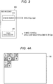
- Fig. 3 is a schematic diagram illustrating an example of the number of sensor pixels of the Si image sensor 110 and the InGaAs image sensor 120.
- the Si image sensor 110 includes 3840 ⁇ 2160 pixels (pix), and the pixels are arrayed in a Bayer array.
- the InGaAs image sensor 120 includes 512 ⁇ 256 pixel (pix). Out of the pixels of the InGaAs image sensor 120, 20 ⁇ 10 pixels (pix) are configured as visible light pixels for alignment in order to align with visible light pixels obtained by the Si image sensor 110. The visible light pixel for alignment is to be described later.
- the Si image sensor 110 may be a sensor including 4096 ⁇ 2160 pixels (pix) or a high-resolution sensor including 4096 ⁇ 2160 pixels (pix) or more (for example, 7680 ⁇ 4320 pixels (pix)).
- the signal processing device 200 includes a white light image processor 202, a separating processor 204, a deformation parameter generating processor 206, an IR image processor 210, and a synthesizing processor 220.
- the white light image processor 202 includes a developing processor 202a and an image quality improving processor 202b.
- the IR image processor 210 includes a filling processor 212, an image quality improving processor 214, a useful information image extracting unit (image extracting unit) 216, a useful information image processor 217, an image deforming/enlarging processor (image conforming unit) 218.
- a Bayer method of combining each pixel with any one of color filters of three colors of red, green, and blue (RGB) is common.
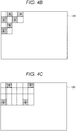
- Figs. 4B and 4C illustrate examples in which a plurality of color filters which transmits a specific wavelength region is applied to each pixel also in the InGaAs image sensor 120, the examples in which a color filter for green used in the Si image sensor 110 is also applied to the InGaAs image sensor 120.
- the color filter for green When the color filter for green is applied to the InGaAs image sensor 120, the color filter for green used in the Si image sensor 110 is applied to the same pixel position as that of the color filter for green of the Si image sensor 110. Therefore, the InGaAs image sensor 120 may image light transmitted through the color filter for green. Then, when an image transmitted through the color filter for green of the Si image sensor 110 and an image transmitted through the color filter for green of the InGaAs image sensor 120 are observed, the same object is observed in the same wavelength region. Therefore, correlation between the images imaged by the two image sensors of the Si image sensor 110 and the InGaAs image sensor 120 may be utilized, and the two images may be aligned on the basis of the correlation.
- the InGaAs image sensor 120 is also sensitive to the visible light wavelength region as described above. Note that, since the alignment is performed on the basis of a pixel value of the pixel in which the color filter for green is arranged, the resolution becomes higher than that in a case where color filters of other colors are used, so that the alignment may be performed with high accuracy.
- Fig. 4B illustrates an example in which the color filters for green are arranged in a relatively large number of pixels in the InGaAs image sensor 120. In this case, the alignment of the Si image sensor 110 and the InGaAs image sensor 120 is focused on, and the alignment accuracy may be improved.
- Fig. 4C illustrates an example in which the number of color filters for green is decreased in the InGaAs image sensor 120 and the number of original pixels of the InGaAs image sensor 120 is increased. In this case, imaging focusing on an image quality of special light by the InGaAs image sensor 120 may be performed.
- the color filter applied to the InGaAs image sensor 120 may be in red or blue.
- the red or blue color filter is applied to the same pixel position as that of the color filter of the same color in the Si image sensor 110.
- Fig. 4D illustrates an example in which the red filter is applied to the InGaAs image sensor 120.
- a transmission filter for near infrared may also be applied to the same pixel position of both the Si image sensor 110 and the InGaAs image sensor 120. Therefore, it is possible to align the images of both the Si image sensor 110 and the InGaAs image sensor 120 on the basis of the pixel value obtained from the pixel transmitted through the transmission filter for near-infrared.
- a single-plate Bayer system which images the respective colors of RGB with a single image sensor is assumed as for the Si image sensor 110; however, the sensor is not limited to this configuration.
- a three-plate system which uses Si image sensors 114, 116, and 118 dedicated to R, G, and B, respectively, in combination with a dichroic mirror 112 may also be employed as illustrated in Fig. 5 .
- Fig. 6 is a characteristic diagram illustrating transmissivity of biological tissue. Note that, the characteristic illustrated in Fig. 6 is disclosed in, for example, Japanese Patent Application Laid-Open No. 2007-75366 .
- a characteristic of transmissivity of water with respect to a wavelength is illustrated in an upper stage, and a characteristic of the transmissivity of the biological tissue of human with respect to the wavelength is illustrated in a lower stage.
- the wavelength along the abscissa corresponds between the characteristics in the upper and lower stages.
- the transmissivity of the fat is specifically higher than the transmissivity of other living tissue and water in a wavelength region from 1400 nm to 1500 nm. That is, it is possible to distinguish the fat from other tissue by combining the pixel of the InGaAs image sensor 120 with a filter which selectively transmits this wavelength region.
- the Si image sensor 110 cannot image the wavelength region from 1400 to 1500 nm.
- the signal value obtained through the filter is a signal of the wavelength region around 1400 nm to 1500 nm.
- the transmissivity of the tissue other than the fat is low.
- the tissue other than the fat has high absorbance.
- the tissue other than the fat absorbs a lot of light to have a dark signal value, and the fat tissue has a bright signal value because of its low absorbance.
- Fig. 7 is a schematic diagram illustrating an image 510 obtained by imaging while combining the InGaAs image sensor 120 with the filter which transmits the wavelength region from 1400 to 1500 nm, and a visible light image 500 obtained by imaging with the Si image sensor 110.
- a state in which a specific organ 530 is imaged is illustrated.
- the organ 530 includes the fat tissue, but the fat tissue cannot be distinguished from the visible light image 500 obtained by imaging with the Si image sensor 110. Especially, in a case where the fat tissue is present inside the organ 530, it is difficult to distinguish or recognize the fat tissue.
- useful information may be extracted from the image 510 of the InGaAs image sensor 120 by the method described above, and the fat tissue has the bright signal value because of its low absorbance. Therefore, a fat portion 540 in the near-infrared image obtained from the InGaAs sensor 120 is a white and bright region in the image 510 in Fig. 7 . Therefore, the fat portion 540 may be extracted by extracting a bright pixel having a pixel value equal to or larger than a predetermined value from the image 510. Therefore, a living body region extracting function of extracting the region of the fat portion 540 as the useful information image may be realized. On the contrary, it is also possible to regard a region with a low pixel value, that is, a dark region in the image 510 as a region with a large moisture content.
- Fig. 7 illustrates a superimposed image 520 obtained by synthesizing the visible light image 500 of the Si image sensor 110 and the useful information image extracted from the image 510 of the InGaAs image sensor 120. From the superimposed image 520, an outline and an appearance of the organ 530 may be recognized from the visible light image 500 of the Si image sensor 110, and the region and state of the fat portion 540 which cannot be distinguished from the image 500 may be distinguished from the useful information image extracted from the image 510 of the InGaAs image sensor 120. Therefore, it becomes possible to surely distinguish a range and a state of the fat portion 540 generated in the organ 530. Therefore, in a case of performing surgical operation on the organ 530, the surgical operation may be performed in consideration of the position and state of the fat portion 540.
- the transmissivity of the fat is high in this wavelength region and the light of the fat portion 540 is transmitted, but the light of other tissue is not transmitted. For this reason, in a case where the fat portion 540 overlaps with another tissue, it is possible to observe a state in which the fat portion 540 is made transparent.
- Fig. 8 is a schematic diagram illustrating an example in which a blood vessel 542 may be recognized through the fat portion 540 in a case where a subject 550 in which the fat portion 540 covers the organ 530 including the blood vessel 542 is imaged.
- the image 500 obtained by imaging the subject 550 by the Si image sensor 110 the organ 530, the fat portion 540, and the blood vessel 542 are imaged; however, since the fat portion 540 is formed on the blood vessel 542, a state of the blood vessel 542 under the fat portion 540 cannot be distinguished.
- the transmissivity of light in the fat portion 540 is high and the transmissivity of light in the blood vessel 542 is low, so that the light penetrates the fat portion 540 and the blood vessel 542 is seen through.
- the state of the blood vessel 542 through the fat portion 540 may be observed in detail. Furthermore, since the superimposed image 520 includes the visible light image 500, color reproduction is natural, and visibility and recognizability may be improved. Note that, in the superimposed image 520 in Fig. 8 also, it is desirable to superimpose the useful information image obtained by extracting the fat portion 540 and the blood vessel 542 from the image 510 of the InGaAs image sensor 120 on the visible light image 500.
- a subject 560 without the fat portion 540 is illustrated for comparison.
- the subject 560 is the same as the subject 550 except that there is no fat portion 540.
- the superimposed image 520 since the blood vessel 542 may be visually recognized through the fat portion 540, it is possible to obtain an image which maintains normal color reproduction while making the fat portion 540 transparent. Therefore, as is apparent from comparison between the subject 550 and the superimposed image 520, it is possible to obtain the superimposed image 520 similar to that in a case where the subject 560 without the fat portion 540 is imaged as the visible light image.
- the blood vessel 542 which cannot be visually recognized due to the fat portion 540 is present in a surgical scene, it is assumed that the blood vessel 542 is erroneously excised.
- the blood vessel 542 may be observed through the fat portion 540, so that a situation in which the blood vessel 542 is erroneously excised during the surgical operation may be certainly suppressed.
- the superimposed image 520 When generating the superimposed image 520, it is also possible to generate the superimposed image 520 by making the IR image a monochrome image, making the color thereof an arbitrary single color, and alpha blending the same with the visible light image. In monochromatization, green or blue which hardly exists in the human body is preferably selected.
- the two images may be simultaneously displayed in one display by a side-by-side (SideBySide) or picture-in-picture (PictureInPicture) method.
- the images may be displayed on two displays.
- not only 2D display but also stereo 3D display may be performed.
- a human wearable display device such as a head-mounted display may be displayed as the display device 400.
- a process performed by the surgical imaging system 1000 according to this embodiment is described with reference to the block diagram in Fig. 1 on the basis of a flowchart in Fig. 9 .
- the process in Fig. 9 is mainly performed by the signal processing device 200.
- step S10 the visible light image imaged by the Si image sensor 110 is obtained.
- the visible light image is subjected to a developing process by the developing processor 202a in the white light image processor 202, and subjected to an image quality improving process by the image quality improving processor 202b.
- the visible light/infrared light image imaged by the InGaAs image sensor 120 is obtained.
- the separating processor 204 separates the visible light/infrared light image into the IR image and the visible light image for alignment.
- the IR image is an image including the pixel other than the pixel in which the color filter for green is arranged illustrated in Fig. 4B .
- the visible light image for alignment is an image including the pixel in which the color filter for green is arranged illustrated in Fig. 4B .
- the IR image has the resolution lower than that of the visible light image imaged by the Si image sensor 110
- the visible light image for alignment has the resolution lower than that of the IR image.
- the deformation parameter generating processor 206 compares the visible light image imaged by the Si image sensor 120 with the visible light image for alignment separated by the separating processor 204. Then, the deformation parameter generating processor 206 generates a deformation parameter for deforming or enlarging the visible light/infrared light image obtained by the InGaAs image sensor 120 in accordance with the visible light image imaged by the Si image sensor 120.
- the Si image sensor 110 and the InGaAs image sensor 120 are assumed to be different in resolution and angle of view depending on lens characteristics thereof, an image size is appropriately changed as the signal processing before superimposed display of the visible light image and the visible light/infrared image is performed.
- the Si image sensor 110 has 4K resolution (3840 ⁇ 1080) and the InGaAs image sensor 120 has HD resolution (1920 ⁇ 1080) lower than that
- the resolution of the visible light/infrared image imaged by the InGaAs image sensor 120 is converted to the resolution corresponding to 4K resolution (up conversion) without changing an aspect ratio thereof.
- the deformation parameter generating processor 206 generates the deformation parameter for changing the image size in such a manner.
- the alignment and distortion correction of the images may be performed as the signal processing before the superimposed display of the visible light image and the visible light/infrared light image is performed.
- positional displacement might occur between the two images.
- the Si image sensor 110 and the InGaAs image sensor 120 the positional displacement according to positions of both the sensors and an optical system occurs.
- a difference in image size or distortion between the Si image sensor 110 and the InGaAs image sensor 120 might occur due to differences in axial chromatic aberration for each wavelength and in lens characteristic.
- the deformation parameter generating processor 206 generates the deformation parameter in order to perform the alignment and distortion correction of such images.
- the subject or camera moves in the frame sequential imaging by time division, it is possible to compare the visible light image of the Si image sensor 110 with the visible light image for alignment of the InGaAs image sensor 120 and perform block matching, thereby performing the alignment.
- the positional displacement according to the positions of both the sensors and the optical system, and the difference in axial chromatic aberration for each wavelength and in lens characteristic may be obtained in advance from specifications of the imaging device 100 and both the sensors.
- the filling processor 212 performs a process of filling the pixel value of the visible light image for alignment on the IR image separated by the separating processor 204. Specifically, a process of interpolating the pixel value of the pixel in which the color filter for green is arranged illustrated in Fig. 4B with the pixel values of surrounding pixels is performed.
- the image quality improving processor 214 performs a process of improving the image quality of the IR image subjected to the filling process by the filling processor 212.
- the image quality improving processor 214 improves the image quality of the IR image imaged by the InGaAs image sensor 120 by the signal processing on the basis of the image information of the visible light image imaged by the Si image sensor 110.
- the image quality improving processor 214 estimates a PSF blur amount (PSF) between the visible light image and the IR image using the visible image imaged by the Si image sensor 110 as a guide. Then, by removing the blur of the IR image so as to conform the blur amount of the visible light image, a contrast of the IR image is improved and the image quality is improved.
- PSF PSF blur amount
- the useful information image extracting unit 216 extracts the useful information image regarding the living body from the IR image subjected to the image quality improving process.
- the useful information image is, for example, image information indicating a region of the fat portion 540 in the IR image as illustrated in Figs. 7 and 8 .
- the visible light image and the IR image are simply synthesized, there is a case in which the fat portion 540 is not displayed with emphasis, so that a process of extracting the region of the fat portion 540 as the useful information image and removing other regions is performed. Therefore, the region of the fat portion 540 may be displayed with emphasis after the synthesis with the visible light image.
- the useful information image processor 217 performs an imaging process on the useful information image.
- the region of the fat portion 540 corresponding to the useful information image is colored in a color (green, blue and the like) which does not exist in the human body. Therefore, the region of the fat portion 540 may be displayed with emphasis after the synthesis with the visible light image.
- the image deforming/enlarging processor 218 applies the deformation parameter to the useful information image to perform a deforming/enlarging process of the useful information image. Therefore, the position and size of the visible light image imaged by the Si image sensor 110 conform to those of the useful information image. Furthermore, by applying the deformation parameter, the axial chromatic aberration for each wavelength and the distortion of the lens characteristic are corrected to the same level in the visible light image imaged by the Si image sensor 110 and the useful information image.
- the synthesizing processor 220 synthesizes the visible light image processed by the white light image processor 202 and the useful information image processed by the IR image processor 210. Information of the synthesized image (superimposed image) generated by the synthesis is transmitted from the signal processing device 200 to the transmitting device 300 and further transmitted to the display device 400.
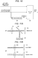
- Fig. 10 is a schematic diagram illustrating the synthesizing processor 220 and a peripheral configuration thereof.
- a selector 222 may be provided on a subsequent stage of the synthesizing processor 220.
- an image before the synthesis that is, the visible light image output from the white light image processor 202 and the useful information image output from the IR image processor 210 are input.
- any one of the synthesized image synthesized by the synthesizing processor 220, the visible light image processed by the white light image processor 202, or the useful information image processed by the IR image processor 210 is selected to be output to the transmitting device 300. Therefore, any one of the synthesized image, the visible light image, or the useful information image is transmitted from the transmitting device 300 to the display device 400, so that these images may be displayed on the display device 400.
- switching of the images by the selector 222 is performed when operation information by a user is input to the selector. In a case where the synthesized image is displayed, the information obtained from the Si image sensor 110 and the information obtained from the InGaAs image sensor 120 may be visually recognized at once, so that the information may be obtained most efficiently.
- the display device 400 displays the image information transmitted from the transmitting device 300.
- Figs. 11A to 11C are schematic diagrams illustrating an optical system of the imaging device 100.
- a "single-eye two-plate system" in which light is introduced from one opening through a lens 122 to be guided to the Si image sensor 110 and the InGaAs image sensor 120 with a splitter 124 arranged inside the imaging device 100 may be employed.
- chromatic aberration on an optical axis varies depending on the wavelength, it is desirable to appropriately design the positions of the lens 122, the Si image sensor 110, and the InGaAs image sensor 120 in order to reduce an influence.
- a "two-lens two-plate system" in which light is introduced from two openings through lenses 126 and 128 to be guided to the Si image sensor 110 and the InGaAs image sensor 120, respectively, may be employed.
- parallax due to the difference in position between the two openings is appropriately corrected when the superimposed image is generated.
- Fig. 11C illustrates an example in which a three-plate system including the dichroic mirror 112 and using the dedicated Si image sensors 114, 116, and 118 for R, G, and B, respectively as in Fig. 5 is employed.
- light is introduced from one opening through a lens 130, the light transmitted through the lens 130 enters a splitter 132, and the light dispersed by the splitter 132 is emitted to each of the dichroic mirror 112 and the InGaAs image sensor 120.
Landscapes
- Health & Medical Sciences (AREA)
- Life Sciences & Earth Sciences (AREA)
- Surgery (AREA)
- Engineering & Computer Science (AREA)
- Physics & Mathematics (AREA)
- Optics & Photonics (AREA)
- Radiology & Medical Imaging (AREA)
- General Health & Medical Sciences (AREA)
- Medical Informatics (AREA)
- Nuclear Medicine, Radiotherapy & Molecular Imaging (AREA)
- Biomedical Technology (AREA)
- Veterinary Medicine (AREA)
- Biophysics (AREA)
- Heart & Thoracic Surgery (AREA)
- Pathology (AREA)
- Molecular Biology (AREA)
- Animal Behavior & Ethology (AREA)
- Public Health (AREA)
- Signal Processing (AREA)
- Multimedia (AREA)
- General Physics & Mathematics (AREA)
- Quality & Reliability (AREA)
- Computer Vision & Pattern Recognition (AREA)
- Theoretical Computer Science (AREA)
- Spectroscopy & Molecular Physics (AREA)
- Endoscopes (AREA)
- Studio Devices (AREA)
Abstract
Description
- The present disclosure relates to a surgical imaging system and a signal processing device of a surgical image.
- Conventionally, for example, following
Patent Document 1 discloses a configuration in which a Si-based CCD, a CMOS camera and the like are used as a first imaging means, and an InGaAs camera, a germanium camera, a vidicon camera and the like are used as a second imaging means, the second imaging means not having sensitivity to a wavelength of visible light. - Patent Document 1: Japanese Patent Application Laid-Open No.
2013-162978 - However, an image sensor using indium gallium arsenide (InGaAs) generally has lower resolution than resolution of a silicon-based image sensor. For this reason, in the technology disclosed in Patent Document described above, for example, in a case of observing a surgical site, it is difficult to obtain a high-resolution image such as a visible light image because of low resolution of the InGaAs camera.
- Therefore, it has been desired to improve the resolution of the image in a case of imaging with an image sensor having light receiving sensitivity in a long wavelength region.
- The present disclosure provides a surgical imaging system including a first image sensor that has light receiving sensitivity in a wavelength region of visible light and images a surgical site, a second image sensor that has light receiving sensitivity in a wavelength region of visible light and near-infrared light and images the surgical site, and a signal processing device that performs a process for displaying a first image imaged by the first image sensor and a second image imaged by the second image sensor.
- Furthermore, the present disclosure provides a signal processing device of a surgical image performing a process for synthesizing to display a first image imaged by a first image sensor that has light receiving sensitivity in a wavelength region of visible light and images a surgical site and a second image imaged by a second image sensor that has light receiving sensitivity in a wavelength region of visible light and near-infrared light and images the surgical site.
- According to the present disclosure, it becomes possible to improve the resolution of the image in a case of imaging with the image sensor having the light receiving sensitivity in the long wavelength region.
- Note that, the effect described above is not necessarily limited, and it is also possible to obtain any one of the effects described in this specification or another effect which may be grasped from this specification together with or in place of the effect described above.
-
-
Fig. 1 is a block diagram illustrating a configuration of a system according to an embodiment of the present disclosure. -
Fig. 2 is a characteristic diagram illustrating spectral sensitivity characteristics of an Si image sensor and an InGaAs image sensor. -
Fig. 3 is a schematic diagram illustrating an example of the number of sensor pixels of the Si image sensor and the InGaAs image sensor. -
Fig. 4A is a schematic diagram illustrating a Bayer method of combining each pixel with any one of color filters of three colors of red, green, and blue (RGB). -
Fig. 4B is a schematic diagram illustrating an example in which a plurality of color filters which transmits a specific wavelength region is applied for each pixel in an InGaAs image sensor. -
Fig. 4C is a schematic diagram illustrating an example in which a plurality of color filters which transmits a specific wavelength region is applied for each pixel in the InGaAs image sensor. -
Fig. 4D illustrates an example in which a red filter is applied to the InGaAs image sensor. -
Fig. 5 is a schematic diagram illustrating an example in which a three-plate system using dedicated Si image sensors for R, G, and B in combination with a dichroic mirror is employed. -
Fig. 6 is a characteristic diagram illustrating transmissivity of living tissue. -
Fig. 7 is a schematic diagram illustrating an image obtained by imaging while combining the InGaAs image sensor with a filter which transmits a wavelength region from 1400 to 1500 nm, and a visible light image obtained by imaging with the Si image sensor. -
Fig. 8 is a schematic diagram illustrating an example in which a blood vessel may be recognized through a fat portion in a case where a subject in which the fat portion covers an organ including the blood vessel is imaged. -
Fig. 9 is a flowchart illustrating a process performed in a system according to this embodiment. -
Fig. 10 is a schematic diagram illustrating a synthesizing processor and a peripheral configuration thereof. -
Fig. 11A is a schematic diagram illustrating an optical system of an imaging device. -
Fig. 11B is a schematic diagram illustrating the optical system of the imaging device. -
Fig. 11C is a schematic diagram illustrating the optical system of the imaging device. - A preferred embodiment of the present disclosure is hereinafter described in detail with reference to the accompanying drawings. Note that, in this specification and the drawings, the components having substantially the same functional configuration are assigned with the same reference sign and the description thereof is not repeated.
- Note that the description is given in the following order.
- 1. Outline of the present disclosure
- 2. Configuration example of system
- 3. Alignment and synthesis of images obtained from two image sensors
- 4. Extraction of useful information image
- 5. Process performed in surgical imaging system according to this embodiment
- 6. Configuration example of optical system
- An imaging device is widely used in order to image the inside of a human body. However, it is actually difficult to correctly determine a state of an organ and the like in the human body only with a normal visible light image. For this reason, it is assumed to mount an InGaAs image sensor sensitive to a near-infrared wavelength region on a surgical imaging system in order to make it easy to visually recognize the inside of the human body, for example, blood vessels and fat regions in deep sites. However, at present, the InGaAs image sensor has a problem of a large pixel size and low resolution as compared with an Si image sensor used in imaging of a conventional visible light image.
- Therefore, in the present disclosure, in order to compensate for the low resolution of the InGaAs image sensor, a surgical imaging system utilizing two imaging elements of the InGaAs image sensor and the Si image sensor is devised. The InGaAs image sensor according to the present disclosure is an image sensor sensitive to a continuous wavelength region from a visible light region to the near-infrared wavelength region and may also obtain a signal in a visible region. That is, in the present disclosure, a maximum value λ1max of a wavelength region of the Si image sensor and a minimum value of a wavelength region of the InGaAs image sensor satisfy a relationship that λ2min is "λ1max>λ2min".
- Especially, in the surgical imaging system, high resolution is required for an image obtained by imaging. According to the present disclosure, in a case where the InGaAs image sensor sensitive to the visible light region to the near-infrared wavelength region is used, it is possible to compensate for relatively low resolution by the InGaAs image sensor by a high-resolution Si image sensor by combining the Si image sensor. Therefore, it is possible to easily visually recognize the blood vessels and fat regions in the deep sites as described above by light receiving sensitivity in the near-infrared wavelength region, and it is possible to obtain a high-resolution image by the Si image sensor. Furthermore, by utilizing correlation between image information of the visible light image imaged by the Si image sensor and image information of the visible light image imaged by the InGaAs image sensor, alignment between the images of both the Si image sensor and the InGaAs image sensor may be performed. Moreover, by synthesizing the image information of the visible light image imaged by the Si image sensor and the visible light image and infrared light image imaged by the InGaAs image sensor, the information obtained from both the sensors may be visually recognized efficiently.
-
Fig. 1 is a block diagram illustrating a configuration of asurgical imaging system 1000 according to an embodiment of the present disclosure. Thesurgical imaging system 1000 observes, for example, the blood vessels, fat regions, fluorescent reactions (fluorescent substance and autofluorescence) and the like in the human body, and is applicable to, for example, an endoscope system, a video microscope system and the like. As illustrated inFig. 1 , thesurgical imaging system 1000 includes animaging device 100, asignal processing device 200, a transmittingdevice 300, and adisplay device 400. - The
imaging device 100 includes two imaging elements of anSi image sensor 110 and anInGaAs image sensor 120. TheSi image sensor 110 and theInGaAs image sensor 120 image the same subject. For this reason, theSi image sensor 110 and theInGaAs image sensor 120 are synchronized by a synchronization signal generated by a synchronizationsignal generating unit 130. The synchronizationsignal generating unit 130 may be provided in theimaging device 100. At the time of imaging, simultaneous imaging by theSi image sensor 110 and theInGaAs image sensor 120 or frame sequential imaging by time division is performed. Note that, signal processing and display are normally performed while imaging in real time, but the signal processing and display may also be performed when reproducing recorded image data. -
Fig. 2 is a characteristic diagram illustrating spectral sensitivity characteristics of theSi image sensor 110 and theInGaAs image sensor 120. As illustrated inFig. 2 , theInGaAs image sensor 120 has wide band light receiving sensitivity including from the visible light region to a long wavelength region. More specifically, theInGaAs image sensor 120 is sensitive to a continuous wavelength region approximately from 350 nm to 1500 nm. On the other hand, theSi image sensor 110 has light receiving sensitivity in the visible light region. Therefore, a high-resolution visible light image is obtained by theSi image sensor 110, and a visible light image and an infrared light image are obtained by theInGaAs image sensor 120. Note that, hereafter, the visible light image and the infrared light image are referred to as a visible light/infrared light image. Furthermore, the infrared light image is also referred to as an IR image. - As a light source used when imaging, a light source capable of emitting a wide band from a visible region to the near-infrared wavelength region may be employed. Furthermore, in a case where the near-infrared wavelength region is used for fluorescence observation, a narrow wavelength light source for exciting fluorescence and a light source in the visible region may be combined.
-
Fig. 3 is a schematic diagram illustrating an example of the number of sensor pixels of theSi image sensor 110 and theInGaAs image sensor 120. As an example, theSi image sensor 110 includes 3840 × 2160 pixels (pix), and the pixels are arrayed in a Bayer array. On the other hand, theInGaAs image sensor 120 includes 512 × 256 pixel (pix). Out of the pixels of theInGaAs image sensor Si image sensor 110. The visible light pixel for alignment is to be described later. Note that, theSi image sensor 110 may be a sensor including 4096 × 2160 pixels (pix) or a high-resolution sensor including 4096 × 2160 pixels (pix) or more (for example, 7680 × 4320 pixels (pix)). - As illustrated in
Fig. 1 , thesignal processing device 200 includes a whitelight image processor 202, a separatingprocessor 204, a deformationparameter generating processor 206, anIR image processor 210, and a synthesizingprocessor 220. The whitelight image processor 202 includes a developingprocessor 202a and an imagequality improving processor 202b. Furthermore, theIR image processor 210 includes a fillingprocessor 212, an imagequality improving processor 214, a useful information image extracting unit (image extracting unit) 216, a usefulinformation image processor 217, an image deforming/enlarging processor (image conforming unit) 218. - In a case of imaging a color image with one
Si image sensor 110, as illustrated inFig.4A , a Bayer method of combining each pixel with any one of color filters of three colors of red, green, and blue (RGB) is common.Figs. 4B and 4C illustrate examples in which a plurality of color filters which transmits a specific wavelength region is applied to each pixel also in theInGaAs image sensor 120, the examples in which a color filter for green used in theSi image sensor 110 is also applied to theInGaAs image sensor 120. - When the color filter for green is applied to the
InGaAs image sensor 120, the color filter for green used in theSi image sensor 110 is applied to the same pixel position as that of the color filter for green of theSi image sensor 110. Therefore, theInGaAs image sensor 120 may image light transmitted through the color filter for green. Then, when an image transmitted through the color filter for green of theSi image sensor 110 and an image transmitted through the color filter for green of theInGaAs image sensor 120 are observed, the same object is observed in the same wavelength region. Therefore, correlation between the images imaged by the two image sensors of theSi image sensor 110 and theInGaAs image sensor 120 may be utilized, and the two images may be aligned on the basis of the correlation. This may be realized by the fact that theInGaAs image sensor 120 is also sensitive to the visible light wavelength region as described above. Note that, since the alignment is performed on the basis of a pixel value of the pixel in which the color filter for green is arranged, the resolution becomes higher than that in a case where color filters of other colors are used, so that the alignment may be performed with high accuracy. -
Fig. 4B illustrates an example in which the color filters for green are arranged in a relatively large number of pixels in theInGaAs image sensor 120. In this case, the alignment of theSi image sensor 110 and theInGaAs image sensor 120 is focused on, and the alignment accuracy may be improved. Furthermore,Fig. 4C illustrates an example in which the number of color filters for green is decreased in theInGaAs image sensor 120 and the number of original pixels of theInGaAs image sensor 120 is increased. In this case, imaging focusing on an image quality of special light by theInGaAs image sensor 120 may be performed. - Note that the color filter applied to the
InGaAs image sensor 120 may be in red or blue. In this case also, the red or blue color filter is applied to the same pixel position as that of the color filter of the same color in theSi image sensor 110.Fig. 4D illustrates an example in which the red filter is applied to theInGaAs image sensor 120. - Furthermore, since the
Si image sensor 110 is also sensitive to the near-infrared region, a transmission filter for near infrared may also be applied to the same pixel position of both theSi image sensor 110 and theInGaAs image sensor 120. Therefore, it is possible to align the images of both theSi image sensor 110 and theInGaAs image sensor 120 on the basis of the pixel value obtained from the pixel transmitted through the transmission filter for near-infrared. - Note that, in this embodiment, a single-plate Bayer system which images the respective colors of RGB with a single image sensor is assumed as for the
Si image sensor 110; however, the sensor is not limited to this configuration. For example, a three-plate system which usesSi image sensors dichroic mirror 112 may also be employed as illustrated inFig. 5 . - Next, a method of extracting a useful information image regarding a living body from the image imaged by the
InGaAs image sensor 120 is described.Fig. 6 is a characteristic diagram illustrating transmissivity of biological tissue. Note that, the characteristic illustrated inFig. 6 is disclosed in, for example, Japanese Patent Application Laid-Open No.2007-75366 - In
Fig. 6 , a characteristic of transmissivity of water with respect to a wavelength is illustrated in an upper stage, and a characteristic of the transmissivity of the biological tissue of human with respect to the wavelength is illustrated in a lower stage. The wavelength along the abscissa corresponds between the characteristics in the upper and lower stages. As illustrated inFig. 6 , it is understood that the transmissivity of the fat is specifically higher than the transmissivity of other living tissue and water in a wavelength region from 1400 nm to 1500 nm. That is, it is possible to distinguish the fat from other tissue by combining the pixel of theInGaAs image sensor 120 with a filter which selectively transmits this wavelength region. Note that, as illustrated inFig. 2 , theSi image sensor 110 cannot image the wavelength region from 1400 to 1500 nm. - When combining the
InGaAs image sensor 120 with the filter which transmits the wavelength region from 1400 nm to 1500 nm and emitting wide band light covering the near-infrared region to image, the signal value obtained through the filter is a signal of the wavelength region around 1400 nm to 1500 nm. - At that time, as illustrated in
Fig. 6 , the transmissivity of the tissue other than the fat is low. In other words, the tissue other than the fat has high absorbance. For this reason, the tissue other than the fat absorbs a lot of light to have a dark signal value, and the fat tissue has a bright signal value because of its low absorbance. -
Fig. 7 is a schematic diagram illustrating animage 510 obtained by imaging while combining theInGaAs image sensor 120 with the filter which transmits the wavelength region from 1400 to 1500 nm, and a visiblelight image 500 obtained by imaging with theSi image sensor 110. In an example illustrated inFig. 7 , as illustrated in the visiblelight image 500, a state in which aspecific organ 530 is imaged is illustrated. Theorgan 530 includes the fat tissue, but the fat tissue cannot be distinguished from the visiblelight image 500 obtained by imaging with theSi image sensor 110. Especially, in a case where the fat tissue is present inside theorgan 530, it is difficult to distinguish or recognize the fat tissue. - On the other hand, useful information may be extracted from the
image 510 of theInGaAs image sensor 120 by the method described above, and the fat tissue has the bright signal value because of its low absorbance. Therefore, afat portion 540 in the near-infrared image obtained from theInGaAs sensor 120 is a white and bright region in theimage 510 inFig. 7 . Therefore, thefat portion 540 may be extracted by extracting a bright pixel having a pixel value equal to or larger than a predetermined value from theimage 510. Therefore, a living body region extracting function of extracting the region of thefat portion 540 as the useful information image may be realized. On the contrary, it is also possible to regard a region with a low pixel value, that is, a dark region in theimage 510 as a region with a large moisture content. -
Fig. 7 illustrates asuperimposed image 520 obtained by synthesizing the visiblelight image 500 of theSi image sensor 110 and the useful information image extracted from theimage 510 of theInGaAs image sensor 120. From thesuperimposed image 520, an outline and an appearance of theorgan 530 may be recognized from the visiblelight image 500 of theSi image sensor 110, and the region and state of thefat portion 540 which cannot be distinguished from theimage 500 may be distinguished from the useful information image extracted from theimage 510 of theInGaAs image sensor 120. Therefore, it becomes possible to surely distinguish a range and a state of thefat portion 540 generated in theorgan 530. Therefore, in a case of performing surgical operation on theorgan 530, the surgical operation may be performed in consideration of the position and state of thefat portion 540. - Furthermore, in a case where the filter which transmits the wavelength region from 1400 nm to 1500 nm is used in the
InGaAs image sensor 120, the transmissivity of the fat is high in this wavelength region and the light of thefat portion 540 is transmitted, but the light of other tissue is not transmitted. For this reason, in a case where thefat portion 540 overlaps with another tissue, it is possible to observe a state in which thefat portion 540 is made transparent. -
Fig. 8 is a schematic diagram illustrating an example in which ablood vessel 542 may be recognized through thefat portion 540 in a case where a subject 550 in which thefat portion 540 covers theorgan 530 including theblood vessel 542 is imaged. In theimage 500 obtained by imaging the subject 550 by theSi image sensor 110, theorgan 530, thefat portion 540, and theblood vessel 542 are imaged; however, since thefat portion 540 is formed on theblood vessel 542, a state of theblood vessel 542 under thefat portion 540 cannot be distinguished. - On the other hand, in the
image 510 obtained by imaging while combining theInGaAs image sensor 120 with the filter which transmits the wavelength region from 1400 to 1500 nm, the transmissivity of light in thefat portion 540 is high and the transmissivity of light in theblood vessel 542 is low, so that the light penetrates thefat portion 540 and theblood vessel 542 is seen through. - Therefore, in the
superimposed image 520 obtained by synthesizing the visiblelight image 500 of theSi image sensor 110 and theimage 510 of theInGaAs image sensor 120, the state of theblood vessel 542 through thefat portion 540 may be observed in detail. Furthermore, since thesuperimposed image 520 includes the visiblelight image 500, color reproduction is natural, and visibility and recognizability may be improved. Note that, in thesuperimposed image 520 inFig. 8 also, it is desirable to superimpose the useful information image obtained by extracting thefat portion 540 and theblood vessel 542 from theimage 510 of theInGaAs image sensor 120 on the visiblelight image 500. - In
Fig. 8 , a subject 560 without thefat portion 540 is illustrated for comparison. The subject 560 is the same as the subject 550 except that there is nofat portion 540. In thesuperimposed image 520, since theblood vessel 542 may be visually recognized through thefat portion 540, it is possible to obtain an image which maintains normal color reproduction while making thefat portion 540 transparent. Therefore, as is apparent from comparison between the subject 550 and thesuperimposed image 520, it is possible to obtain thesuperimposed image 520 similar to that in a case where the subject 560 without thefat portion 540 is imaged as the visible light image. - For example, if the
blood vessel 542 which cannot be visually recognized due to thefat portion 540 is present in a surgical scene, it is assumed that theblood vessel 542 is erroneously excised. In such a case, by using the superimposedimage 520 according to this embodiment, theblood vessel 542 may be observed through thefat portion 540, so that a situation in which theblood vessel 542 is erroneously excised during the surgical operation may be certainly suppressed. - When generating the
superimposed image 520, it is also possible to generate thesuperimposed image 520 by making the IR image a monochrome image, making the color thereof an arbitrary single color, and alpha blending the same with the visible light image. In monochromatization, green or blue which hardly exists in the human body is preferably selected. - Furthermore, in the above-described example, an example of synthesizing the visible
light image 500 of theSi image sensor 110 and theimage 510 of theInGaAs image sensor 120 is described; however, the two images may be simultaneously displayed in one display by a side-by-side (SideBySide) or picture-in-picture (PictureInPicture) method. Furthermore, the images may be displayed on two displays. Furthermore, not only 2D display but also stereo 3D display may be performed. Moreover, a human wearable display device such as a head-mounted display may be displayed as thedisplay device 400. - Next, a process performed by the
surgical imaging system 1000 according to this embodiment is described with reference to the block diagram inFig. 1 on the basis of a flowchart inFig. 9 . The process inFig. 9 is mainly performed by thesignal processing device 200. First, at step S10, the visible light image imaged by theSi image sensor 110 is obtained. The visible light image is subjected to a developing process by the developingprocessor 202a in the whitelight image processor 202, and subjected to an image quality improving process by the imagequality improving processor 202b. - At next step S12, the visible light/infrared light image imaged by the
InGaAs image sensor 120 is obtained. At next step S14, the separatingprocessor 204 separates the visible light/infrared light image into the IR image and the visible light image for alignment. Here, the IR image is an image including the pixel other than the pixel in which the color filter for green is arranged illustrated inFig. 4B . Furthermore, the visible light image for alignment is an image including the pixel in which the color filter for green is arranged illustrated inFig. 4B . Note that, the IR image has the resolution lower than that of the visible light image imaged by theSi image sensor 110, and the visible light image for alignment has the resolution lower than that of the IR image. - At next step S16, the deformation
parameter generating processor 206 compares the visible light image imaged by theSi image sensor 120 with the visible light image for alignment separated by the separatingprocessor 204. Then, the deformationparameter generating processor 206 generates a deformation parameter for deforming or enlarging the visible light/infrared light image obtained by theInGaAs image sensor 120 in accordance with the visible light image imaged by theSi image sensor 120. - Since the
Si image sensor 110 and theInGaAs image sensor 120 are assumed to be different in resolution and angle of view depending on lens characteristics thereof, an image size is appropriately changed as the signal processing before superimposed display of the visible light image and the visible light/infrared image is performed. For example, in a case where theSi image sensor 110 has 4K resolution (3840 × 1080) and theInGaAs image sensor 120 has HD resolution (1920 × 1080) lower than that, the resolution of the visible light/infrared image imaged by theInGaAs image sensor 120 is converted to the resolution corresponding to 4K resolution (up conversion) without changing an aspect ratio thereof. The deformationparameter generating processor 206 generates the deformation parameter for changing the image size in such a manner. - Furthermore, the alignment and distortion correction of the images may be performed as the signal processing before the superimposed display of the visible light image and the visible light/infrared light image is performed. For example, in a case of performing the frame sequential imaging by time division, if the subject or the camera moves, positional displacement might occur between the two images. Furthermore, in a case of simultaneously imaging by the
Si image sensor 110 and theInGaAs image sensor 120, the positional displacement according to positions of both the sensors and an optical system occurs. Alternatively, a difference in image size or distortion between theSi image sensor 110 and theInGaAs image sensor 120 might occur due to differences in axial chromatic aberration for each wavelength and in lens characteristic. The deformationparameter generating processor 206 generates the deformation parameter in order to perform the alignment and distortion correction of such images. In a case where the subject or camera moves in the frame sequential imaging by time division, it is possible to compare the visible light image of theSi image sensor 110 with the visible light image for alignment of theInGaAs image sensor 120 and perform block matching, thereby performing the alignment. Furthermore, the positional displacement according to the positions of both the sensors and the optical system, and the difference in axial chromatic aberration for each wavelength and in lens characteristic may be obtained in advance from specifications of theimaging device 100 and both the sensors. - Note that it is also possible to create a depth map by parallax estimation using image data in the same position of the visible light image and the visible light/infrared light image after the alignment is performed.
- At next step S18, the filling
processor 212 performs a process of filling the pixel value of the visible light image for alignment on the IR image separated by the separatingprocessor 204. Specifically, a process of interpolating the pixel value of the pixel in which the color filter for green is arranged illustrated inFig. 4B with the pixel values of surrounding pixels is performed. - At next step S20, the image
quality improving processor 214 performs a process of improving the image quality of the IR image subjected to the filling process by the fillingprocessor 212. The imagequality improving processor 214 improves the image quality of the IR image imaged by theInGaAs image sensor 120 by the signal processing on the basis of the image information of the visible light image imaged by theSi image sensor 110. For example, the imagequality improving processor 214 estimates a PSF blur amount (PSF) between the visible light image and the IR image using the visible image imaged by theSi image sensor 110 as a guide. Then, by removing the blur of the IR image so as to conform the blur amount of the visible light image, a contrast of the IR image is improved and the image quality is improved. - At next step S22, the useful information
image extracting unit 216 extracts the useful information image regarding the living body from the IR image subjected to the image quality improving process. The useful information image is, for example, image information indicating a region of thefat portion 540 in the IR image as illustrated inFigs. 7 and8 . In a case where the visible light image and the IR image are simply synthesized, there is a case in which thefat portion 540 is not displayed with emphasis, so that a process of extracting the region of thefat portion 540 as the useful information image and removing other regions is performed. Therefore, the region of thefat portion 540 may be displayed with emphasis after the synthesis with the visible light image. - At next step S24, the useful
information image processor 217 performs an imaging process on the useful information image. Here, for example, the region of thefat portion 540 corresponding to the useful information image is colored in a color (green, blue and the like) which does not exist in the human body. Therefore, the region of thefat portion 540 may be displayed with emphasis after the synthesis with the visible light image. - At next step S26, the image deforming/enlarging
processor 218 applies the deformation parameter to the useful information image to perform a deforming/enlarging process of the useful information image. Therefore, the position and size of the visible light image imaged by theSi image sensor 110 conform to those of the useful information image. Furthermore, by applying the deformation parameter, the axial chromatic aberration for each wavelength and the distortion of the lens characteristic are corrected to the same level in the visible light image imaged by theSi image sensor 110 and the useful information image. At next step S28, the synthesizingprocessor 220 synthesizes the visible light image processed by the whitelight image processor 202 and the useful information image processed by theIR image processor 210. Information of the synthesized image (superimposed image) generated by the synthesis is transmitted from thesignal processing device 200 to the transmittingdevice 300 and further transmitted to thedisplay device 400. -
Fig. 10 is a schematic diagram illustrating the synthesizingprocessor 220 and a peripheral configuration thereof. As illustrated inFig. 10 , aselector 222 may be provided on a subsequent stage of the synthesizingprocessor 220. To theselector 222, in addition to the synthesized image synthesized by the synthesizingprocessor 220, an image before the synthesis, that is, the visible light image output from the whitelight image processor 202 and the useful information image output from theIR image processor 210 are input. - From the
selector 222, any one of the synthesized image synthesized by the synthesizingprocessor 220, the visible light image processed by the whitelight image processor 202, or the useful information image processed by theIR image processor 210 is selected to be output to the transmittingdevice 300. Therefore, any one of the synthesized image, the visible light image, or the useful information image is transmitted from the transmittingdevice 300 to thedisplay device 400, so that these images may be displayed on thedisplay device 400. Note that switching of the images by theselector 222 is performed when operation information by a user is input to the selector. In a case where the synthesized image is displayed, the information obtained from theSi image sensor 110 and the information obtained from theInGaAs image sensor 120 may be visually recognized at once, so that the information may be obtained most efficiently. - At next step S30, the
display device 400 displays the image information transmitted from the transmittingdevice 300. At next step S32, it is determined whether or not to finish the process. In a case where the process is not finished, the procedure returns to step S10 to perform the subsequent process. -
Figs. 11A to 11C are schematic diagrams illustrating an optical system of theimaging device 100. As the optical system, as illustrated inFig. 11A , a "single-eye two-plate system" in which light is introduced from one opening through alens 122 to be guided to theSi image sensor 110 and theInGaAs image sensor 120 with asplitter 124 arranged inside theimaging device 100 may be employed. In this case, since chromatic aberration on an optical axis varies depending on the wavelength, it is desirable to appropriately design the positions of thelens 122, theSi image sensor 110, and theInGaAs image sensor 120 in order to reduce an influence. - Furthermore, as illustrated in
Fig. 11B , a "two-lens two-plate system" in which light is introduced from two openings throughlenses Si image sensor 110 and theInGaAs image sensor 120, respectively, may be employed. In this case, parallax due to the difference in position between the two openings is appropriately corrected when the superimposed image is generated. - Furthermore,
Fig. 11C illustrates an example in which a three-plate system including thedichroic mirror 112 and using the dedicatedSi image sensors Fig. 5 is employed. In this case, light is introduced from one opening through alens 130, the light transmitted through thelens 130 enters asplitter 132, and the light dispersed by thesplitter 132 is emitted to each of thedichroic mirror 112 and theInGaAs image sensor 120. - As described above, according to this embodiment, it is possible to improve the visibility of the blood vessels and fat regions difficult to determine only with the normal visible light image. Furthermore, it becomes possible to improve a sense of resolution of the image imaged by the
InGaAs image sensor 120. Moreover, simultaneous observation becomes possible by superimposed display of the images imaged by theInGaAs image sensor 120 and theSi image sensor 110. - Although the preferred embodiment of the present disclosure is described above in detail with reference to the attached drawings, the technical scope of the present disclosure is not limited to such examples. It is clear that one of ordinary skill in the technical field of the present disclosure may conceive of various modifications and corrections within the scope of the technical idea recited in claims and it is understood that they also naturally belong to the technical scope of the present disclosure.
- Furthermore, the effects described in this specification are merely illustrative or exemplary, and are not limiting. That is, the technology according to the present disclosure may exhibit other effects obvious to those skilled in the art from the description of this specification together with or in place of the effects described above.
- Note that, the following configuration also belongs to the technical scope of the present disclosure.
- (1) A surgical imaging system including:
- a first image sensor that has light receiving sensitivity in a wavelength region of visible light and images a surgical site;
- a second image sensor that has light receiving sensitivity in a wavelength region of visible light and near-infrared light and images the surgical site; and
- a signal processing device that performs a process for displaying a first image imaged by the first image sensor and a second image imaged by the second image sensor.
- (2) The surgical imaging system according to (1) described above, in which resolution of the first image sensor is higher than resolution of the second image sensor.
- (3) The surgical imaging system according to (1) or (2) described above,
in which the first image sensor includes a color filter in a predetermined color arranged for each pixel, and
the second image sensor includes a color filter in the same color as the color of the color filter in a pixel position corresponding to a pixel position of the color filter of the first image sensor. - (4) The surgical imaging system according to (3) described above, in which the predetermined color is green.
- (5) The surgical imaging system according to any one of (1) to (4) described above, in which the first image sensor is an image sensor including Si and has resolution of 3840 × 2160 pixels or more.
- (6) The surgical imaging system according to any one of (1) to (5) described above, in which the second image sensor is an image sensor including InGaAs.
- (7) The surgical imaging system according to (3) described above, in which the signal processing device includes an image conforming unit that conforms the first image to the second image on the basis of a pixel value obtained through the color filter of the first image sensor and a pixel value obtained through the color filter of the second image sensor.
- (8) The surgical imaging system according to (3) described above, in which the signal processing device includes a filling processor that calculates a pixel value in a state in which the color filter is not arranged in the pixel position in which the color filter is provided of the second image sensor.
- (9) The surgical imaging system according to any one of (1) to (8) described above, in which the signal processing device includes a synthesizing processor that synthesizes the first image and the second image.
- (10) The surgical imaging system according to any one of (1) to (9) described above, in which the signal processing device includes an image quality improving processor that improves an image quality of the second image on the basis of the first image.
- (11) The surgical imaging system according to any one of (1) to (10) described above, in which the signal processing device includes an image extracting unit that extracts a specific region from the second image.
- (12) The surgical imaging system according to (11) described above,
in which the second image sensor includes a filter that transmits light in a predetermined wavelength region, and
the image extracting unit extracts the specific region on the basis of a pixel value obtained through the filter. - (13) The surgical imaging system according to (12) described above, in which the predetermined wavelength region is a wavelength region not shorter than 1300 nm and not longer than 1400 nm.
- (14) The surgical imaging system according to (11) described above, in which the signal processing device includes an image processor that assigns a predetermined color to the specific region.
- (15) The surgical imaging system according to (14) described above, in which the predetermined color is green or blue.
- (16) The surgical imaging system according to any one of (1) to (15) described above, in which the first image sensor and the second image sensor image fat or a blood vessel in a human body.
- (17) A signal processing device of a surgical image, performing a process for synthesizing to display a first image imaged by a first image sensor that has light receiving sensitivity in a wavelength region of visible light and images a surgical site and a second image imaged by a second image sensor that has light receiving sensitivity in a wavelength region of visible light and near-infrared light and images the surgical site.
-
- 100
- Imaging device
- 110
- Si image sensor
- 120
- InGaAs image sensor
- 200
- Signal processing device
- 212
- Filling processor
- 214
- Image quality improving processor
- 216
- Useful information image extracting unit
- 217
- Useful information image processor
- 218
- Image deforming/enlarging processor
- 220
- Synthesizing processor
- 1000
- Surgical imaging system
Claims (17)
- A surgical imaging system comprising:a first image sensor that has light receiving sensitivity in a wavelength region of visible light and images a surgical site;a second image sensor that has light receiving sensitivity in a wavelength region of visible light and near-infrared light and images the surgical site; anda signal processing device that performs a process for displaying a first image imaged by the first image sensor and a second image imaged by the second image sensor.
- The surgical imaging system according to claim 1, wherein resolution of the first image sensor is higher than resolution of the second image sensor.
- The surgical imaging system according to claim 1,
wherein the first image sensor includes a color filter in a predetermined color arranged for each pixel, and
the second image sensor includes a color filter in a same color as the color of the color filter in a pixel position corresponding to a pixel position of the color filter of the first image sensor. - The surgical imaging system according to claim 3, wherein the predetermined color is green.
- The surgical imaging system according to claim 1, wherein the first image sensor is an image sensor including Si and has resolution of 3840 × 2160 pixels or more.
- The surgical imaging system according to claim 1, wherein the second image sensor is an image sensor including InGaAs.
- The surgical imaging system according to claim 3, wherein the signal processing device includes an image conforming unit that conforms the first image to the second image on a basis of a pixel value obtained through the color filter of the first image sensor and a pixel value obtained through the color filter of the second image sensor.
- The surgical imaging system according to claim 3, wherein the signal processing device includes a filling processor that calculates a pixel value in a state in which the color filter is not arranged in the pixel position in which the color filter is provided of the second image sensor.
- The surgical imaging system according to claim 1, wherein the signal processing device includes a synthesizing processor that synthesizes the first image and the second image.
- The surgical imaging system according to claim 1, wherein the signal processing device includes an image quality improving processor that improves an image quality of the second image on a basis of the first image.
- The surgical imaging system according to claim 1, wherein the signal processing device includes an image extracting unit that extracts a specific region from the second image.
- The surgical imaging system according to claim 11,
wherein the second image sensor includes a filter that transmits light in a predetermined wavelength region, and
the image extracting unit extracts the specific region on a basis of a pixel value obtained through the filter. - The surgical imaging system according to claim 12, wherein the predetermined wavelength region is a wavelength region not shorter than 1300 nm and not longer than 1400 nm.
- The surgical imaging system according to claim 11, wherein the signal processing device includes an image processor that assigns a predetermined color to the specific region.
- The surgical imaging system according to claim 14, wherein the predetermined color is green or blue.
- The surgical imaging system according to claim 1, wherein the first image sensor and the second image sensor image fat or a blood vessel in a human body.
- A signal processing device of a surgical image, performing a process for synthesizing to display a first image imaged by a first image sensor that has light receiving sensitivity in a wavelength region of visible light and images a surgical site and a second image imaged by a second image sensor that has light receiving sensitivity in a wavelength region of visible light and near-infrared light and images the surgical site.
Applications Claiming Priority (2)
| Application Number | Priority Date | Filing Date | Title |
|---|---|---|---|
| JP2017124074 | 2017-06-26 | ||
| PCT/JP2018/020326 WO2019003751A1 (en) | 2017-06-26 | 2018-05-28 | Surgical imaging system and signal processing device for surgical image |
Publications (2)
| Publication Number | Publication Date |
|---|---|
| EP3646771A1 true EP3646771A1 (en) | 2020-05-06 |
| EP3646771A4 EP3646771A4 (en) | 2020-07-01 |
Family
ID=64740514
Family Applications (1)
| Application Number | Title | Priority Date | Filing Date |
|---|---|---|---|
| EP18822911.6A Withdrawn EP3646771A4 (en) | 2017-06-26 | 2018-05-28 | SURGICAL IMAGING SYSTEM AND SIGNAL PROCESSING DEVICE FOR SURGICAL IMAGE |
Country Status (4)
| Country | Link |
|---|---|
| US (1) | US20200126220A1 (en) |
| EP (1) | EP3646771A4 (en) |
| JP (1) | JP7127644B2 (en) |
| WO (1) | WO2019003751A1 (en) |
Families Citing this family (7)
| Publication number | Priority date | Publication date | Assignee | Title |
|---|---|---|---|---|
| US20200093420A1 (en) * | 2018-09-21 | 2020-03-26 | Covidien Lp | Surgical imaging system and methods of use thereof |
| JP6955307B2 (en) * | 2018-11-06 | 2021-10-27 | 富士フイルム株式会社 | Imaging lens and imaging device |
| US10902572B1 (en) | 2019-10-09 | 2021-01-26 | Karl Storz Imaging, Inc. | Enhanced fluorescence imaging for imaging system |
| TW202137749A (en) | 2020-02-26 | 2021-10-01 | 日商索尼半導體解決方案公司 | Imaging device, imaging method, and electronic apparatus |
| US12081863B2 (en) * | 2020-03-19 | 2024-09-03 | Sony Group Corporation | Information processing with alignment of images of first and second imaging devices |
| CN115605124A (en) * | 2020-05-26 | 2023-01-13 | 登士柏西诺德公司(Us) | Methods and devices for multimodal soft tissue diagnosis |
| JP2024537409A (en) * | 2021-10-18 | 2024-10-10 | アースレックス インコーポレイテッド | Surgical camera system with high dynamic range fluorescence imaging - Patents.com |
Family Cites Families (10)
| Publication number | Priority date | Publication date | Assignee | Title |
|---|---|---|---|---|
| JP3930359B2 (en) * | 2002-03-29 | 2007-06-13 | オリンパス株式会社 | Sentinel lymph node detection apparatus and detection method |
| JP2007075366A (en) | 2005-09-14 | 2007-03-29 | Olympus Medical Systems Corp | Infrared observation system |
| JP5148054B2 (en) * | 2005-09-15 | 2013-02-20 | オリンパスメディカルシステムズ株式会社 | Imaging system |
| JP6044012B2 (en) | 2012-02-13 | 2016-12-14 | 愛知県 | Detection system for detection target part |
| WO2015010098A1 (en) * | 2013-07-19 | 2015-01-22 | Google Inc. | Asymmetric sensor array for capturing images |
| US9824443B2 (en) * | 2013-09-10 | 2017-11-21 | Sony Corporation | Image processing device, image processing method, and program |
| CN107205613B (en) * | 2015-01-22 | 2019-02-12 | 奥林巴斯株式会社 | camera |
| WO2017064760A1 (en) * | 2015-10-13 | 2017-04-20 | オリンパス株式会社 | Laminated image pickup element, image processing apparatus, image processing method, and program |
| JP6132251B1 (en) * | 2016-05-19 | 2017-05-24 | パナソニックIpマネジメント株式会社 | Endoscope and endoscope system |
| CN106236006B (en) * | 2016-08-31 | 2017-11-14 | 杨晓峰 | 3D optical molecular image laparoscope imaging systems |
-
2018
- 2018-05-28 EP EP18822911.6A patent/EP3646771A4/en not_active Withdrawn
- 2018-05-28 JP JP2019526706A patent/JP7127644B2/en active Active
- 2018-05-28 WO PCT/JP2018/020326 patent/WO2019003751A1/en not_active Ceased
- 2018-05-28 US US16/621,246 patent/US20200126220A1/en not_active Abandoned
Also Published As
| Publication number | Publication date |
|---|---|
| EP3646771A4 (en) | 2020-07-01 |
| JP7127644B2 (en) | 2022-08-30 |
| WO2019003751A1 (en) | 2019-01-03 |
| JPWO2019003751A1 (en) | 2020-04-23 |
| US20200126220A1 (en) | 2020-04-23 |
Similar Documents
| Publication | Publication Date | Title |
|---|---|---|
| EP3646771A1 (en) | Surgical imaging system and signal processing device for surgical image | |
| US10966592B2 (en) | 3D endoscope apparatus and 3D video processing apparatus | |
| CN107137053B (en) | Medical examination device such as microscope or endoscope using pseudo-color | |
| US10708478B2 (en) | Image transformation and display for fluorescent and visible imaging | |
| JP6908039B2 (en) | Image processing equipment, image processing methods, programs, and image processing systems | |
| JP4009626B2 (en) | Endoscope video signal processor | |
| US10729310B2 (en) | Endoscope image processing devices | |
| US20190289179A1 (en) | Endoscope image processing device and endoscope image processing method | |
| US9635343B2 (en) | Stereoscopic endoscopic image processing apparatus | |
| JP7449736B2 (en) | Medical image processing device and medical observation system | |
| US11159781B2 (en) | Image processing apparatus, camera apparatus, and output control method | |
| JP6296365B2 (en) | Surgical endoscope camera control unit | |
| CN112274105A (en) | Operating microscope, image processing device and image processing method | |
| US20190037201A1 (en) | Image processing apparatus, camera apparatus, and image processing method | |
| US7822247B2 (en) | Endoscope processor, computer program product, endoscope system, and endoscope image playback apparatus | |
| JP7649114B2 (en) | Optical imaging device and method for improving displayed images | |
| JP6091311B2 (en) | Imaging device | |
| US11051004B2 (en) | Image processing apparatus, camera apparatus, and image processing method | |
| JP6896053B2 (en) | Systems and methods for creating HDR monochrome images of fluorescent phosphors, especially for microscopes and endoscopes | |
| JP6042798B2 (en) | Image processing apparatus and endoscope system | |
| JP2014094175A (en) | Image processing system for electronic endoscope | |
| EP4275577A1 (en) | Method, processor, and medical fluorescence observation device using two color images and color cameras for fluorescence and white-light | |
| EP4275578A1 (en) | Method, processor, and medical fluorescence observation device using a color-dependent color conversion function | |
| EP3991633A1 (en) | Microscope system for use in eye surgery and corresponding system, methods and computer programs | |
| JP2025517190A (en) | Method for recording fluorescence using two color images, processor and medical fluorescence observation device |
Legal Events
| Date | Code | Title | Description |
|---|---|---|---|
| STAA | Information on the status of an ep patent application or granted ep patent |
Free format text: STATUS: THE INTERNATIONAL PUBLICATION HAS BEEN MADE |
|
| PUAI | Public reference made under article 153(3) epc to a published international application that has entered the european phase |
Free format text: ORIGINAL CODE: 0009012 |
|
| STAA | Information on the status of an ep patent application or granted ep patent |
Free format text: STATUS: REQUEST FOR EXAMINATION WAS MADE |
|
| 17P | Request for examination filed |
Effective date: 20191210 |
|
| AK | Designated contracting states |
Kind code of ref document: A1 Designated state(s): AL AT BE BG CH CY CZ DE DK EE ES FI FR GB GR HR HU IE IS IT LI LT LU LV MC MK MT NL NO PL PT RO RS SE SI SK SM TR |
|
| AX | Request for extension of the european patent |
Extension state: BA ME |
|
| A4 | Supplementary search report drawn up and despatched |
Effective date: 20200529 |
|
| RIC1 | Information provided on ipc code assigned before grant |
Ipc: H04N 5/232 20060101ALI20200525BHEP Ipc: H04N 9/09 20060101ALI20200525BHEP Ipc: A61B 1/00 20060101ALI20200525BHEP Ipc: H04N 5/225 20060101ALI20200525BHEP Ipc: G02B 5/20 20060101ALI20200525BHEP Ipc: A61B 1/045 20060101AFI20200525BHEP Ipc: A61B 1/04 20060101ALI20200525BHEP |
|
| DAV | Request for validation of the european patent (deleted) | ||
| DAX | Request for extension of the european patent (deleted) | ||
| RAP3 | Party data changed (applicant data changed or rights of an application transferred) |
Owner name: SONY GROUP CORPORATION |
|
| STAA | Information on the status of an ep patent application or granted ep patent |
Free format text: STATUS: THE APPLICATION HAS BEEN WITHDRAWN |
|
| 18W | Application withdrawn |
Effective date: 20220905 |