EP3646695B1 - Triplex greensmower open foot platform cover - Google Patents
Triplex greensmower open foot platform cover Download PDFInfo
- Publication number
- EP3646695B1 EP3646695B1 EP19204962.5A EP19204962A EP3646695B1 EP 3646695 B1 EP3646695 B1 EP 3646695B1 EP 19204962 A EP19204962 A EP 19204962A EP 3646695 B1 EP3646695 B1 EP 3646695B1
- Authority
- EP
- European Patent Office
- Prior art keywords
- cutting unit
- triplex greensmower
- platform
- triplex
- greensmower
- Prior art date
- Legal status (The legal status is an assumption and is not a legal conclusion. Google has not performed a legal analysis and makes no representation as to the accuracy of the status listed.)
- Active
Links
Images




Classifications
-
- A—HUMAN NECESSITIES
- A01—AGRICULTURE; FORESTRY; ANIMAL HUSBANDRY; HUNTING; TRAPPING; FISHING
- A01D—HARVESTING; MOWING
- A01D67/00—Undercarriages or frames specially adapted for harvesters or mowers; Mechanisms for adjusting the frame; Platforms
-
- A—HUMAN NECESSITIES
- A01—AGRICULTURE; FORESTRY; ANIMAL HUSBANDRY; HUNTING; TRAPPING; FISHING
- A01D—HARVESTING; MOWING
- A01D34/00—Mowers; Mowing apparatus of harvesters
- A01D34/01—Mowers; Mowing apparatus of harvesters characterised by features relating to the type of cutting apparatus
- A01D34/412—Mowers; Mowing apparatus of harvesters characterised by features relating to the type of cutting apparatus having rotating cutters
- A01D34/42—Mowers; Mowing apparatus of harvesters characterised by features relating to the type of cutting apparatus having rotating cutters having cutters rotating about a horizontal axis, e.g. cutting-cylinders
- A01D34/43—Mowers; Mowing apparatus of harvesters characterised by features relating to the type of cutting apparatus having rotating cutters having cutters rotating about a horizontal axis, e.g. cutting-cylinders mounted on a vehicle, e.g. a tractor, or drawn by an animal or a vehicle
- A01D34/44—Mowers; Mowing apparatus of harvesters characterised by features relating to the type of cutting apparatus having rotating cutters having cutters rotating about a horizontal axis, e.g. cutting-cylinders mounted on a vehicle, e.g. a tractor, or drawn by an animal or a vehicle with two or more cutters
-
- A—HUMAN NECESSITIES
- A01—AGRICULTURE; FORESTRY; ANIMAL HUSBANDRY; HUNTING; TRAPPING; FISHING
- A01D—HARVESTING; MOWING
- A01D34/00—Mowers; Mowing apparatus of harvesters
- A01D34/01—Mowers; Mowing apparatus of harvesters characterised by features relating to the type of cutting apparatus
- A01D34/412—Mowers; Mowing apparatus of harvesters characterised by features relating to the type of cutting apparatus having rotating cutters
- A01D34/42—Mowers; Mowing apparatus of harvesters characterised by features relating to the type of cutting apparatus having rotating cutters having cutters rotating about a horizontal axis, e.g. cutting-cylinders
- A01D34/62—Other details
-
- A—HUMAN NECESSITIES
- A01—AGRICULTURE; FORESTRY; ANIMAL HUSBANDRY; HUNTING; TRAPPING; FISHING
- A01D—HARVESTING; MOWING
- A01D67/00—Undercarriages or frames specially adapted for harvesters or mowers; Mechanisms for adjusting the frame; Platforms
- A01D67/02—Protection against weather
Definitions
- the present invention relates to grass mowing machines, and more specifically to triplex greensmowers.
- Grass mowing machines used to mow golf courses, parks, and athletic fields where a high quality of cut is desired may include three or more reel cutting units.
- Triplex greensmowers have two forward reel cutting units followed by a center or rear reel cutting unit positioned under the vehicle frame and in front of the operator station.
- Each reel cutting unit on a triplex greensmower may be mounted to a lift arm that may be used to raise and lower the cutting unit between a mowing position and a transport position.
- Reel cutting units have front and rear rollers, spiral cutting blades rotating in close proximity to a bedknife, and may have a removable grass catcher mounted in front of the cutting unit.
- triplex greensmower that provides better quality of cut and reduces the tendency of reel cutting units to leave marks or step cuts on the turf.
- a triplex greensmower that reduces the impact of each reel cutting unit when it is lowered to the mowing position with the front and rear rollers parallel to the ground to distribute the load evenly.
- a triplex greensmower that eliminates the pendulum effect in which reel cutting units tend to swing from the lift arms.
- a triplex greensmower that provides improved access to the center or rear reel cutting unit for service, and for emptying and replacing the grass catcher.
- a triplex greensmower that provides improved access to the center or rear reel cutting unit while blocking or preventing debris discharged by the cutting unit from reaching the operator when a grass catcher is not used.
- EP-A-2082916 discloses an example of a foot platform for a triplex greensmower.
- US-9,370,139 relates to a reel mower with a pivotal footrest for providing access to the centre rear cutting unit of the reel mower, for example a triplex riding greensmower.
- a triplex greensmower with a triplex greensmower open foot platform is provided as set out in claim 1. Preferred features of the greensmower are set out in the dependent claims.
- Fig. 1 shows an example of a triplex greensmower 100 that includes left and right front reel cutting units 102, 104 positioned side-by-side forwardly of left and right drive wheels 106, 108, and center or rear reel cutting unit 110 positioned behind the drive wheels and in front of steerable rear wheel 112.
- Grass catchers 114, 116 and 118 may be removably attached to the front of each of the reel cutting units.
- An electric or hydraulic motor may drive each cutting reel and may be mounted to one side of the reel cutting unit.
- the triplex greensmower may have operator seat 120 between the drive wheels and rear wheel, console 122 adjacent the operator seat, and roll over protection system or POPS 124 attached to the frame behind and alongside the operator seat.
- Step 126 may be mounted to the frame of the triplex greensmower to the left side and below the operator seat, and steering wheel 128 may be mounted on steering column 130 to the right and in front of the operator seat.
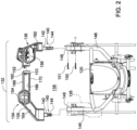
- Fig. 2 shows an example of a triplex greensmower 100 with an open foot platform 132 having a left platform section 134 and right platform section 136.
- the left and right platform sections may be metal castings, molded plastic, composite or other materials that define the perimeter of an opening 138 in front of operator seat 120. From the operator seat, an operator may have an unobstructed sight line through opening 138 in triplex greensmower open foot platform 132 for visibility of grass catcher 118 and center cutting unit 110. An operator also may lift the grass catcher through the opening in the triplex greensmower open foot platform for emptying and replacement.
- an operator may use the opening in the triplex greensmower open foot platform to service the center cutting unit, and may remove or replace the center cutting unit through the opening.
- the opening in the triplex greensmower open foot platform has width and length dimensions larger than the width and length of the center reel cutting unit or grass catcher.
- the opening may have side-to-side and front-to-back dimensions of 32 inches (about 81cm) and 22 inches (about 56cm) respectively, which are larger than dimensions of the reel cutting unit or grass catcher.
- At least one of the platform sections may be removable from the triplex greensmower without requiring tools.
- at least one of the platform sections includes a coupling 140 that extends rearwardly from the platform section and may be used by the operator to manually engage and disengage the platform section from the triplex greensmower frame.
- Each coupling 140 may include a base portion 142 and a post 144 extending from the base.
- Each post 144 may slide into one end of main frame support tube 146, and each base portion 142 may slide into channel 148 extending over the end of the main frame support tube.
- the base portion and channel each may have rectangular cross sections to prevent twisting or pivoting of each coupling relative to the frame.
- the triplex greensmower open foot platform 132 may be locked or secured to the triplex greensmower frame.
- one or more locking members 150, 151 such as a bolt, pin or fastener, may be inserted through holes aligned in coupling 140, and in main frame support tube 146 and/or channel 148.
- the triplex greensmower open foot platform may include a latch 152 to lock or secure together the left and right platform sections 134, 136 when both sections are engaged to the triplex greensmower frame.
- latch 152 may be provided on the forward end of right platform section 136 and may capture an abutment 153 on the forward end of left platform section 134.
- a slot and tab or other mechanism may be used for securing or locking together the left and right platform sections. Securing or locking together the left and right platform sections also helps prevent disengagement of each coupling 140 from main frame support tube 146 and channel 148.
- the triplex greensmower open foot platform may include left and right footrests 154, 156, and neck portions 158, 160, 162 extending from or between the left and right footrests.
- the neck portions may be narrower than the footrests.
- one or more openings 164, 166 may be provided through the neck portions to provide the operator with unobstructed sight lines and visibility to the front reel cutting units.
- the neck portions may include parallel bars 168, 170 that are spaced apart.
- the triplex greensmower open foot platform 180 includes left and right platform sections 182, 184, and opening 185.
- the left and right platform sections may not be secured or locked together.
- This example may also not include a neck portion or latch extending between the left and right platform sections.
- Each of the left and right platform sections may include a coupling 186 that includes a base portion 188 and a post 190.
- Each post 190 may slide into one end of main frame support tube 192, and each base portion 188 may slide into channel 194 extending over the end of the main frame support tube.
- the base and channel may have rectangular cross sections to prevent twisting or pivoting of the coupling relative to the frame.
- One or more locking members 196 such as a bolt, pin or fastener may lock either coupling to the frame.
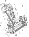
- the triplex greensmower 100 may include lift system 200 for each reel cutting unit.
- Each lift system 200 may allow each reel cutting unit to follow ground contours when mowing, and may be used to raise and lower a reel cutting unit between the mowing and transport position.
- Each lift system 200 may include roll axis 202 where upper lift arm 204 may be pivotably mounted to lower lift arm 206.
- Roll axis 202 may be behind the reel cutting unit, at a height or elevation between the top of the cutting unit and the center of gravity (CG) of the cutting unit, and preferably within about 50 mm of the CG.
- CG center of gravity
- Each lift system 200 may include yaw axis 208 which may be where yoke mount 224 is connected to the forward end of upper lift arm 204, in front of the CG of the cutting unit.
- Each lift system 200 also may include lift axis 226 where lower lift arm 206 may be pivotably mounted to the vehicle frame behind the cutting unit, lifter support axis 228 where lifter support 228 may be pivotably mounted to lower lift arm 206, and cutting unit mounting axis 230 where yoke mount 224 may be pivotably connected to the reel cutting unit side panels 232, 234.
- Each axis may be positioned at a different location relative to the CG of the cutting unit.
- the triplex greensmower lift system also may include a pair of flexible linkages 212, 214 between lifter support 210 and the cutting unit to hold the cutting unit still when it is raised from the ground. Additionally, the lift system may include tension spring 216 connected between the forward end of upper lift arm 204 and triplex greensmower frame member 205 behind and above the reel cutting unit.
- the triplex greensmower lift system 200 may include upper lift arm 204 that is pivotably mounted with bearings 220, 222 to lower lift arm 206 behind the reel cutting unit.
- the mounting location of the upper lift arm provides a roll axis 202 that is between the top of the cutting unit and the center of gravity (CG) of the cutting unit, and preferably within about 50 mm from the CG of the cutting unit. From roll axis 202, upper lift arm 204 may extend forwardly and upwardly where it may be attached to yoke mount 224.
- Tension spring 216 connected between the forward end of upper lift arm 204 and triplex greensmower frame member 205, may provide stability to the roll of the cutting unit and also may reduce the tendency of the cutting unit to leave marks on the turf by transfer of weight of the cutting unit to the vehicle frame.
- the triplex greensmower lift system 200 may include yoke mount 224 which provides yaw axis 208 to give the reel cutting unit a full range of steering as the vehicle turns on an axis perpendicular to the ground plane.
- the location of the yaw axis is forward of the CG of the reel cutting unit and preferably at least about 90 mm forward of the CG of the cutting unit.
- Yoke mount 224 may be pivotably connected to a sleeve on the forward end of upper lift arm 204.
- a vertical bolt or rod 242 may be inserted through the yoke mount and sleeve, enabling the yoke mount to pivot on vertical yaw axis 208.
- the front of yoke mount 224 may include a pair of channels or groove where upper rod 244 and lower rod 246 may be secured and clamped with clamping member 248.
- the yoke mount does not provide a pitch axis at this location.
- the yoke mount may include yoke arms 252, 254 attached to the ends of the upper and lower rods, and extending downwardly where they may be pivotably mounted to side panels 232, 234 of the reel cutting unit at cutting unit mounting axis 230.
- Cutting unit mounting axis 230 provides a pitch axis for the reel cutting unit that is below and forward of the reel cutting unit's CG.
- clamping member 248 may be loosened and releases to allow shifting the reel cutting unit left or right relative to the yoke mount.
- a stop may be provided on at least one of the rods to define a desired position.
- the triplex greensmower lift system 200 may include lift axis 226 between lower lift arm 206 and the triplex greensmower frame, lifter support axis 228 between lifter support 210 and lower lift arm 206, and cutting unit mounting axis 230 between yoke arms 252, 254 and the cutting unit side panels 232, 234.
- Each of the lift axis 226, lifter support axis 228 and cutting unit mounting axis 230 may provide a pitch axis that allows the reel cutting unit to follow ground contours by pitching on an axis that is horizontal and perpendicular to the direction of travel, and also may allow the reel cutting unit to stay approximately level when it is raised and lowered between the mowing position and transport position.
- Tension spring 216 also may bias the reel cutting unit upwardly relative to lift axis 226 and reduce ground pressure of the cutting unit on the turf during mowing.
- the tension spring on the left front reel cutting unit may be connected at a location offset to the left side of the upper lift arm
- the tension spring on the right front reel cutting unit may be connected at a location offset to the right side of the upper lift arm.
- each of the tension springs may reduce ground pressure and prevent marks or step cuts by biasing the left side of the left front reel cutting unit upwardly during left turns, and biasing the right side of the right front reel cutting unit upwardly during right tums.
- the triplex greensmower lift system 200 may include lifter support 210 and a pair of flexible linkages 212, 214 that hold the reel cutting unit approximately level and prevent swinging of the cutting unit while it is raised to the transport position.
- lift cylinder 236, which may be a hydraulic cylinder or electric actuator, may be retracted.
- Lift cylinder 236 may be connected to lifter support 210, and retraction of the lift cylinder pivots the lifter support upwardly on lifter support axis 228.
- a pair of flexible linkages 212, 214 such as a pair of chains, may connect each leg of the U- shaped lifter support 210 to the reel cutting unit behind the cutting unit's center of gravity (CG).
- CG center of gravity
- Yoke arms 252, 254 may be pivotably connected to the reel cutting unit in front of its center of gravity.
- lifter support 210 may pull up the pair of flexible linkages 212, 214 to raise the rear of the cutting unit while the yoke arms the front of the cutting unit.
- the lifter support and pair of flexible linkages also may hold the cutting unit approximately level, and prevent swinging of the cutting unit.
- the lift cylinder may retract further to pivot up lower lift arm 206 and upper lift arm 204 on lift axis 226 to raise the cutting unit to the transport position.
- Tension spring 216 connected between the upper lift arm and frame member 205, may assist the lift cylinder when raising the cutting unit to the transport position.
- the triplex greensmower lift system 200 may hold the reel cutting unit approximately level and prevent swinging of the cutting unit while it is transported, and when it is lowered to the mowing position.
- lift cylinder 236 may be extended to pivot lower lift arm 206 and upper lift arm 204 downwardly together on lift axis 226.
- Lifter support 210 and flexible linkages 212, 214 may hold the cutting unit approximately level so that the rear of the cutting unit and rear roller 238 reach the turf along with the front of the cutting unit and front roller 240.
- Tension spring 216 may dampen or reduce the impact of the cutting unit on the turf.
- lift cylinder 236 may extend further to pivot lifter support 210 downwardly on lifter support axis 228, removing any tension in the pair of flexible linkages so the cutting unit can roll, yaw and pitch during mowing.
- Figs. 7 and 8 show an embodiment of triplex greensmower 100 according to the claimed invention having open foot platform cover 270 removably attached to open foot platform 132.
- Open foot platform cover may substantially cover opening 138 in front of operator seat 120, including the forward portion of center or rear reel cutting unit 110.
- the open foot platform cover may be positioned directly above at least the front roller 240 of center or rear reel cutting 110, and also over any other parts of the center or rear reel cutting unit that extend in front of operator seat 120.
- Open foot platform cover 270 may be a flexible semi-transparent fabric with a plurality of elastic bands or straps 272 at or adjacent its perimeter.
- the semi-transparent fabric should allow the center or rear reel cutting unit 110 to be visible to the operator while mowing.
- Hooks 274 may be attached to each of the elastic bands or straps for fastening the cover to open foot platform 132.
- the hooks may engage left and right platform sections 134, 136, allowing easy removal of the cover from the open foot platform when servicing the center or rear reel cutting unit.
- the open foot platform cover may block grass and debris that is discharged from the front of the center or rear reel cutting unit while mowing without using a grass catcher.
- the cover may block grass and debris from reaching the legs of an operator in the seated position.
Landscapes
- Life Sciences & Earth Sciences (AREA)
- Environmental Sciences (AREA)
- Harvester Elements (AREA)
Description
- The present invention relates to grass mowing machines, and more specifically to triplex greensmowers.
- Grass mowing machines used to mow golf courses, parks, and athletic fields where a high quality of cut is desired, may include three or more reel cutting units. Triplex greensmowers have two forward reel cutting units followed by a center or rear reel cutting unit positioned under the vehicle frame and in front of the operator station. Each reel cutting unit on a triplex greensmower may be mounted to a lift arm that may be used to raise and lower the cutting unit between a mowing position and a transport position. Reel cutting units have front and rear rollers, spiral cutting blades rotating in close proximity to a bedknife, and may have a removable grass catcher mounted in front of the cutting unit.
- There is a need for a triplex greensmower that provides better quality of cut and reduces the tendency of reel cutting units to leave marks or step cuts on the turf. There is a need for a triplex greensmower that reduces the impact of each reel cutting unit when it is lowered to the mowing position with the front and rear rollers parallel to the ground to distribute the load evenly. There is a need for a triplex greensmower that eliminates the pendulum effect in which reel cutting units tend to swing from the lift arms. There also is a need for a triplex greensmower that provides improved access to the center or rear reel cutting unit for service, and for emptying and replacing the grass catcher. There also is a need for a triplex greensmower that provides improved access to the center or rear reel cutting unit while blocking or preventing debris discharged by the cutting unit from reaching the operator when a grass catcher is not used.
-
EP-A-2082916 discloses an example of a foot platform for a triplex greensmower.US-9,370,139 - A triplex greensmower with a triplex greensmower open foot platform is provided as set out in claim 1. Preferred features of the greensmower are set out in the dependent claims.
-
-
Fig. 1 is a top view of a triplex greensmower. -
Fig. 2 is an exploded top view of a triplex greensmower open foot platform . -
Fig. 3 is an exploded top view of a triplex greensmower open foot platform=. -
Fig. 4 is a perspective view of a triplex greensmower lift system on a left front reel cutting unit. -
Fig. 5 is a side view of a triplex greensmower lift system on a left front reel cutting unit in the mowing position. -
Fig. 6 is a side view of a triplex greensmower lift system on a left front reel cutting unit in the transport position. -
Fig. 7 is a perspective view of a triplex greensmower open foot platform with a cover over the center reel cutting unit according to one embodiment of the claimed invention. -
Fig. 8 is an exploded top view of a triplex greensmower open foot platform with a cover over the center reel cutting unit according to one embodiment of the claimed invention. -
Fig. 1 shows an example of atriplex greensmower 100 that includes left and right frontreel cutting units right drive wheels reel cutting unit 110 positioned behind the drive wheels and in front of steerablerear wheel 112.Grass catchers operator seat 120 between the drive wheels and rear wheel,console 122 adjacent the operator seat, and roll over protection system or POPS 124 attached to the frame behind and alongside the operator seat.Step 126 may be mounted to the frame of the triplex greensmower to the left side and below the operator seat, andsteering wheel 128 may be mounted onsteering column 130 to the right and in front of the operator seat. -
Fig. 2 shows an example of atriplex greensmower 100 with anopen foot platform 132 having aleft platform section 134 andright platform section 136. The left and right platform sections may be metal castings, molded plastic, composite or other materials that define the perimeter of anopening 138 in front ofoperator seat 120. From the operator seat, an operator may have an unobstructed sight line through opening 138 in triplex greensmoweropen foot platform 132 for visibility ofgrass catcher 118 andcenter cutting unit 110. An operator also may lift the grass catcher through the opening in the triplex greensmower open foot platform for emptying and replacement. Additionally, an operator may use the opening in the triplex greensmower open foot platform to service the center cutting unit, and may remove or replace the center cutting unit through the opening. The opening in the triplex greensmower open foot platform has width and length dimensions larger than the width and length of the center reel cutting unit or grass catcher. For example, the opening may have side-to-side and front-to-back dimensions of 32 inches (about 81cm) and 22 inches (about 56cm) respectively, which are larger than dimensions of the reel cutting unit or grass catcher. - In the example shown in
Fig. 2 , at least one of the platform sections may be removable from the triplex greensmower without requiring tools. For example, at least one of the platform sections includes acoupling 140 that extends rearwardly from the platform section and may be used by the operator to manually engage and disengage the platform section from the triplex greensmower frame. Eachcoupling 140 may include abase portion 142 and apost 144 extending from the base. Eachpost 144 may slide into one end of mainframe support tube 146, and eachbase portion 142 may slide intochannel 148 extending over the end of the main frame support tube. The base portion and channel each may have rectangular cross sections to prevent twisting or pivoting of each coupling relative to the frame. - The triplex greensmower
open foot platform 132 may be locked or secured to the triplex greensmower frame. For example, one or morelocking members coupling 140, and in mainframe support tube 146 and/orchannel 148. - The triplex greensmower open foot platform may include a
latch 152 to lock or secure together the left andright platform sections latch 152 may be provided on the forward end ofright platform section 136 and may capture anabutment 153 on the forward end ofleft platform section 134. Alternatively, a slot and tab or other mechanism may be used for securing or locking together the left and right platform sections. Securing or locking together the left and right platform sections also helps prevent disengagement of eachcoupling 140 from mainframe support tube 146 andchannel 148. - The triplex greensmower open foot platform may include left and
right footrests neck portions more openings parallel bars - In the example shown in
Fig. 3 , the triplex greensmoweropen foot platform 180 includes left andright platform sections coupling 186 that includes abase portion 188 and apost 190. Eachpost 190 may slide into one end of mainframe support tube 192, and eachbase portion 188 may slide intochannel 194 extending over the end of the main frame support tube. The base and channel may have rectangular cross sections to prevent twisting or pivoting of the coupling relative to the frame. One or more lockingmembers 196, such as a bolt, pin or fastener may lock either coupling to the frame. - As shown in
Figs. 4 - 6 , thetriplex greensmower 100 may includelift system 200 for each reel cutting unit. Eachlift system 200 may allow each reel cutting unit to follow ground contours when mowing, and may be used to raise and lower a reel cutting unit between the mowing and transport position. Eachlift system 200 may includeroll axis 202 whereupper lift arm 204 may be pivotably mounted tolower lift arm 206.Roll axis 202 may be behind the reel cutting unit, at a height or elevation between the top of the cutting unit and the center of gravity (CG) of the cutting unit, and preferably within about 50 mm of the CG. Eachlift system 200 may includeyaw axis 208 which may be whereyoke mount 224 is connected to the forward end ofupper lift arm 204, in front of the CG of the cutting unit. Eachlift system 200 also may includelift axis 226 wherelower lift arm 206 may be pivotably mounted to the vehicle frame behind the cutting unit,lifter support axis 228 wherelifter support 228 may be pivotably mounted tolower lift arm 206, and cuttingunit mounting axis 230 where yoke mount 224 may be pivotably connected to the reel cuttingunit side panels flexible linkages lifter support 210 and the cutting unit to hold the cutting unit still when it is raised from the ground. Additionally, the lift system may includetension spring 216 connected between the forward end ofupper lift arm 204 and triplexgreensmower frame member 205 behind and above the reel cutting unit. - The triplex
greensmower lift system 200 may includeupper lift arm 204 that is pivotably mounted withbearings lower lift arm 206 behind the reel cutting unit. The mounting location of the upper lift arm provides aroll axis 202 that is between the top of the cutting unit and the center of gravity (CG) of the cutting unit, and preferably within about 50 mm from the CG of the cutting unit. Fromroll axis 202,upper lift arm 204 may extend forwardly and upwardly where it may be attached toyoke mount 224. Positioning the roll axis in close proximity to the cutting unit's CG minimizes gravity-induced positional displacement of the cutting unit when mowing on hillsides, reduces the possibility of unlapping (leaving uncut strips between cutting units), and reduces the pendulum effect, which is the tendency of a cutting unit to swing when raised in the transport position.Tension spring 216, connected between the forward end ofupper lift arm 204 and triplexgreensmower frame member 205, may provide stability to the roll of the cutting unit and also may reduce the tendency of the cutting unit to leave marks on the turf by transfer of weight of the cutting unit to the vehicle frame. - The triplex
greensmower lift system 200 may includeyoke mount 224 which providesyaw axis 208 to give the reel cutting unit a full range of steering as the vehicle turns on an axis perpendicular to the ground plane. The location of the yaw axis is forward of the CG of the reel cutting unit and preferably at least about 90 mm forward of the CG of the cutting unit.Yoke mount 224 may be pivotably connected to a sleeve on the forward end ofupper lift arm 204. A vertical bolt orrod 242 may be inserted through the yoke mount and sleeve, enabling the yoke mount to pivot onvertical yaw axis 208. The front ofyoke mount 224 may include a pair of channels or groove whereupper rod 244 andlower rod 246 may be secured and clamped with clampingmember 248. The yoke mount does not provide a pitch axis at this location. Instead, the yoke mount may includeyoke arms side panels unit mounting axis 230. Cuttingunit mounting axis 230 provides a pitch axis for the reel cutting unit that is below and forward of the reel cutting unit's CG. Additionally, clampingmember 248 may be loosened and releases to allow shifting the reel cutting unit left or right relative to the yoke mount. A stop may be provided on at least one of the rods to define a desired position. - The triplex
greensmower lift system 200 may includelift axis 226 betweenlower lift arm 206 and the triplex greensmower frame,lifter support axis 228 betweenlifter support 210 andlower lift arm 206, and cuttingunit mounting axis 230 betweenyoke arms unit side panels lift axis 226,lifter support axis 228 and cuttingunit mounting axis 230 may provide a pitch axis that allows the reel cutting unit to follow ground contours by pitching on an axis that is horizontal and perpendicular to the direction of travel, and also may allow the reel cutting unit to stay approximately level when it is raised and lowered between the mowing position and transport position.Tension spring 216 also may bias the reel cutting unit upwardly relative to liftaxis 226 and reduce ground pressure of the cutting unit on the turf during mowing. Preferably, the tension spring on the left front reel cutting unit may be connected at a location offset to the left side of the upper lift arm, and the tension spring on the right front reel cutting unit may be connected at a location offset to the right side of the upper lift arm. As a result, each of the tension springs may reduce ground pressure and prevent marks or step cuts by biasing the left side of the left front reel cutting unit upwardly during left turns, and biasing the right side of the right front reel cutting unit upwardly during right tums. - The triplex
greensmower lift system 200 may includelifter support 210 and a pair offlexible linkages Fig. 6 ,lift cylinder 236, which may be a hydraulic cylinder or electric actuator, may be retracted.Lift cylinder 236 may be connected to liftersupport 210, and retraction of the lift cylinder pivots the lifter support upwardly onlifter support axis 228. A pair offlexible linkages lifter support 210 to the reel cutting unit behind the cutting unit's center of gravity (CG).Yoke arms lifter support 210 may pull up the pair offlexible linkages lower lift arm 206 andupper lift arm 204 onlift axis 226 to raise the cutting unit to the transport position.Tension spring 216, connected between the upper lift arm andframe member 205, may assist the lift cylinder when raising the cutting unit to the transport position. - The triplex
greensmower lift system 200 may hold the reel cutting unit approximately level and prevent swinging of the cutting unit while it is transported, and when it is lowered to the mowing position. To lower the reel cutting unit,lift cylinder 236 may be extended to pivotlower lift arm 206 andupper lift arm 204 downwardly together onlift axis 226.Lifter support 210 andflexible linkages rear roller 238 reach the turf along with the front of the cutting unit andfront roller 240.Tension spring 216 may dampen or reduce the impact of the cutting unit on the turf. As the cutting unit reaches the turf,lift cylinder 236 may extend further to pivotlifter support 210 downwardly onlifter support axis 228, removing any tension in the pair of flexible linkages so the cutting unit can roll, yaw and pitch during mowing. -
Figs. 7 and8 show an embodiment oftriplex greensmower 100 according to the claimed invention having openfoot platform cover 270 removably attached to openfoot platform 132. Open foot platform cover may substantially cover opening 138 in front ofoperator seat 120, including the forward portion of center or rearreel cutting unit 110. As shown inFig. 7 , the open foot platform cover may be positioned directly above at least thefront roller 240 of center or rear reel cutting 110, and also over any other parts of the center or rear reel cutting unit that extend in front ofoperator seat 120. Openfoot platform cover 270 may be a flexible semi-transparent fabric with a plurality of elastic bands orstraps 272 at or adjacent its perimeter. The semi-transparent fabric should allow the center or rearreel cutting unit 110 to be visible to the operator while mowing.Hooks 274 may be attached to each of the elastic bands or straps for fastening the cover to openfoot platform 132. For example, the hooks may engage left andright platform sections
Claims (7)
- A triplex greensmower (100) with an open foot platform (132; 180), wherein the platform (132; 180) comprises:a left platform section (134; 182) and a right platform section (136; 184), each section removably attached to the triplex greensmower (100) with a coupling (140; 186) extending rearwardly from each section;the left platform section (134; 182) and the right platform section (136; 184) defining a perimeter of an opening (138; 185) located in front of an operator seat (120) when the platform (132; 180) is attached to the triplex greensmower (100), the opening (138; 185) having a larger length and width than a center reel cutting unit (110) of the triplex greensmower (100);the triplex greensmower being characterised in that:
a semi-transparent fabric cover (270) is removably attached to the left platform section (134; 182) and the right platform section (136; 184) over the center reel cutting unit (110) of the triplex greensmower (100), the semi-transparent fabric cover allowing the center reel cutting unit (110) to be visible to an operator while mowing. - The triplex greensmower (100) of claim 1 further comprising a latch (152) between the left platform section (134; 182) and the right platform section (136; 184).
- The triplex greensmower (100) of claim 1 or 2 further comprising a locking member (150, 151) between one of the platform sections (134, 136; 182, 184) and a frame member.
- The triplex greensmower (100) of claim 1, 2 or 3 wherein the coupling (140; 186) includes a rectangular base and a post extending from the base.
- The triplex greensmower (100) of any one of the preceding claims, wherein each of the left and right platform sections (134, 136; 182, 184) including a foot rest (154, 156).
- The triplex greensmower (100) of claim 5 further comprising a neck portion (158, 160, 162) extending between the foot rests on the pair of removable platform sections (134, 136; 182, 184).
- The triplex greensmower (100) of claim 5 or claim 6 wherein each removable platform section includes a coupling (140; 186) with a rectangular base that engages a rectangular channel.
Applications Claiming Priority (1)
| Application Number | Priority Date | Filing Date | Title |
|---|---|---|---|
| US16/175,349 US11032972B2 (en) | 2018-10-30 | 2018-10-30 | Triplex greensmower open foot platform cover |
Publications (2)
| Publication Number | Publication Date |
|---|---|
| EP3646695A1 EP3646695A1 (en) | 2020-05-06 |
| EP3646695B1 true EP3646695B1 (en) | 2024-02-14 |
Family
ID=68342718
Family Applications (1)
| Application Number | Title | Priority Date | Filing Date |
|---|---|---|---|
| EP19204962.5A Active EP3646695B1 (en) | 2018-10-30 | 2019-10-23 | Triplex greensmower open foot platform cover |
Country Status (2)
| Country | Link |
|---|---|
| US (1) | US11032972B2 (en) |
| EP (1) | EP3646695B1 (en) |
Citations (1)
| Publication number | Priority date | Publication date | Assignee | Title |
|---|---|---|---|---|
| US9370139B2 (en) * | 2008-06-27 | 2016-06-21 | The Toro Company | Reel mower with pivotal footrest providing access to center rear cutting unit |
Family Cites Families (17)
| Publication number | Priority date | Publication date | Assignee | Title |
|---|---|---|---|---|
| GB191416105A (en) | 1914-07-06 | 1915-06-03 | Charles Campbell Worthington | Improvements in and relating to Gang Lawn Mowers. |
| US3716975A (en) * | 1972-01-20 | 1973-02-20 | A Smith | Safety shield for powered lawn equipment |
| GB2178634B (en) | 1985-06-10 | 1988-10-19 | Ransomes Sims & Jefferies Plc | Grass cutting machine |
| US4930298A (en) | 1989-03-16 | 1990-06-05 | The Toro Company | Cutting unit cover |
| US5331794A (en) * | 1993-12-06 | 1994-07-26 | Reichle Andrew L | Mower shield |
| US5406778A (en) | 1994-02-03 | 1995-04-18 | Ransomes America Corporation | Electric drive riding greens mower |
| US5842707A (en) | 1997-08-19 | 1998-12-01 | Smith; Jeffrey Hayes | Single wheel zero turn riding sulky for use with a self-propelled vehicle |
| US6032441A (en) | 1997-11-13 | 2000-03-07 | The Toro Company | Triplex trim mower with laterally adjustable cutting units |
| US6226876B1 (en) * | 1998-08-13 | 2001-05-08 | Thomas E. Ezell | Debris shield for hand-held string trimmer |
| US7475530B2 (en) | 2007-03-02 | 2009-01-13 | Textron Inc. | Articulating swing-out arm |
| US7637090B2 (en) | 2007-10-17 | 2009-12-29 | Deere & Company | Roller configuration having reduced overlap for a grass mowing machine |
| US7894957B2 (en) | 2008-01-28 | 2011-02-22 | Textron Innovations Inc. | Dynamic tactical steering feedback |
| US7644567B2 (en) * | 2008-05-01 | 2010-01-12 | Cnh America Llc | Flexible tall crop pusher |
| CA2777084C (en) * | 2012-05-08 | 2013-05-28 | John W. Houston | Device for blocking ejection of crop material from an auger platform of an agricultural harvester |
| US10064328B2 (en) | 2016-08-10 | 2018-09-04 | Deere & Company | Grass mowing machine for high power applications |
| US10433485B2 (en) | 2017-08-08 | 2019-10-08 | Deere & Company | Triplex greensmower open foot platform |
| US10358017B1 (en) * | 2018-11-08 | 2019-07-23 | William R. Harris | Shield for zero-turn mowers |
-
2018
- 2018-10-30 US US16/175,349 patent/US11032972B2/en active Active
-
2019
- 2019-10-23 EP EP19204962.5A patent/EP3646695B1/en active Active
Patent Citations (1)
| Publication number | Priority date | Publication date | Assignee | Title |
|---|---|---|---|---|
| US9370139B2 (en) * | 2008-06-27 | 2016-06-21 | The Toro Company | Reel mower with pivotal footrest providing access to center rear cutting unit |
Also Published As
| Publication number | Publication date |
|---|---|
| EP3646695A1 (en) | 2020-05-06 |
| US20200128748A1 (en) | 2020-04-30 |
| US11032972B2 (en) | 2021-06-15 |
Similar Documents
| Publication | Publication Date | Title |
|---|---|---|
| EP3440916B1 (en) | Triplex greensmower lift system | |
| US9220193B2 (en) | Reel mower with easily removable cutting units having easily removable motors | |
| US7610739B2 (en) | Riding mower | |
| US20170202138A1 (en) | Wheeled lawnmower for walking driver | |
| EP3440915B1 (en) | Triplex greensmower open foot platform | |
| EP1685758B1 (en) | Coupling mechanism and mowing machine | |
| EP3874933B1 (en) | Height of cut and rake adjustment system | |
| US20030024223A1 (en) | Electric vehicle and reel mower gang | |
| US11032972B2 (en) | Triplex greensmower open foot platform cover | |
| EP2181580B1 (en) | Reel mower cutting unit | |
| EP2702857B1 (en) | Reel mower grass catcher carrier | |
| US20170223892A1 (en) | Lawnmower with flexible cutter deck assembly | |
| US7765779B2 (en) | Latch mechanism for retaining grass catcher on reel mower cutting unit | |
| US20140215994A1 (en) | Reel mower grass catcher carrier | |
| US7051500B2 (en) | ATV mower deck adapter | |
| US11212961B2 (en) | Drive-over mower deck with retractable front rollers | |
| CN211713865U (en) | Grass-mowing protection device |
Legal Events
| Date | Code | Title | Description |
|---|---|---|---|
| PUAI | Public reference made under article 153(3) epc to a published international application that has entered the european phase |
Free format text: ORIGINAL CODE: 0009012 |
|
| STAA | Information on the status of an ep patent application or granted ep patent |
Free format text: STATUS: THE APPLICATION HAS BEEN PUBLISHED |
|
| AK | Designated contracting states |
Kind code of ref document: A1 Designated state(s): AL AT BE BG CH CY CZ DE DK EE ES FI FR GB GR HR HU IE IS IT LI LT LU LV MC MK MT NL NO PL PT RO RS SE SI SK SM TR |
|
| AX | Request for extension of the european patent |
Extension state: BA ME |
|
| STAA | Information on the status of an ep patent application or granted ep patent |
Free format text: STATUS: REQUEST FOR EXAMINATION WAS MADE |
|
| STAA | Information on the status of an ep patent application or granted ep patent |
Free format text: STATUS: EXAMINATION IS IN PROGRESS |
|
| 17P | Request for examination filed |
Effective date: 20201102 |
|
| RBV | Designated contracting states (corrected) |
Designated state(s): AL AT BE BG CH CY CZ DE DK EE ES FI FR GB GR HR HU IE IS IT LI LT LU LV MC MK MT NL NO PL PT RO RS SE SI SK SM TR |
|
| 17Q | First examination report despatched |
Effective date: 20201208 |
|
| GRAP | Despatch of communication of intention to grant a patent |
Free format text: ORIGINAL CODE: EPIDOSNIGR1 |
|
| STAA | Information on the status of an ep patent application or granted ep patent |
Free format text: STATUS: GRANT OF PATENT IS INTENDED |
|
| INTG | Intention to grant announced |
Effective date: 20230921 |
|
| RIN1 | Information on inventor provided before grant (corrected) |
Inventor name: ROTHROCK, JUSTIN Inventor name: WAITT, TAYLOR Inventor name: SHOAF, GILBERT |
|
| GRAS | Grant fee paid |
Free format text: ORIGINAL CODE: EPIDOSNIGR3 |
|
| GRAA | (expected) grant |
Free format text: ORIGINAL CODE: 0009210 |
|
| STAA | Information on the status of an ep patent application or granted ep patent |
Free format text: STATUS: THE PATENT HAS BEEN GRANTED |
|
| AK | Designated contracting states |
Kind code of ref document: B1 Designated state(s): AL AT BE BG CH CY CZ DE DK EE ES FI FR GB GR HR HU IE IS IT LI LT LU LV MC MK MT NL NO PL PT RO RS SE SI SK SM TR |
|
| REG | Reference to a national code |
Ref country code: GB Ref legal event code: FG4D |
|
| REG | Reference to a national code |
Ref country code: CH Ref legal event code: EP |
|
| REG | Reference to a national code |
Ref country code: DE Ref legal event code: R096 Ref document number: 602019046420 Country of ref document: DE |
|
| REG | Reference to a national code |
Ref country code: IE Ref legal event code: FG4D |
|
| REG | Reference to a national code |
Ref country code: LT Ref legal event code: MG9D |
|
| REG | Reference to a national code |
Ref country code: NL Ref legal event code: MP Effective date: 20240214 |
|
| PG25 | Lapsed in a contracting state [announced via postgrant information from national office to epo] |
Ref country code: IS Free format text: LAPSE BECAUSE OF FAILURE TO SUBMIT A TRANSLATION OF THE DESCRIPTION OR TO PAY THE FEE WITHIN THE PRESCRIBED TIME-LIMIT Effective date: 20240614 |
|
| PG25 | Lapsed in a contracting state [announced via postgrant information from national office to epo] |
Ref country code: LT Free format text: LAPSE BECAUSE OF FAILURE TO SUBMIT A TRANSLATION OF THE DESCRIPTION OR TO PAY THE FEE WITHIN THE PRESCRIBED TIME-LIMIT Effective date: 20240214 |
|
| PG25 | Lapsed in a contracting state [announced via postgrant information from national office to epo] |
Ref country code: GR Free format text: LAPSE BECAUSE OF FAILURE TO SUBMIT A TRANSLATION OF THE DESCRIPTION OR TO PAY THE FEE WITHIN THE PRESCRIBED TIME-LIMIT Effective date: 20240515 |
|
| REG | Reference to a national code |
Ref country code: AT Ref legal event code: MK05 Ref document number: 1656190 Country of ref document: AT Kind code of ref document: T Effective date: 20240214 |
|
| PG25 | Lapsed in a contracting state [announced via postgrant information from national office to epo] |
Ref country code: HR Free format text: LAPSE BECAUSE OF FAILURE TO SUBMIT A TRANSLATION OF THE DESCRIPTION OR TO PAY THE FEE WITHIN THE PRESCRIBED TIME-LIMIT Effective date: 20240214 Ref country code: RS Free format text: LAPSE BECAUSE OF FAILURE TO SUBMIT A TRANSLATION OF THE DESCRIPTION OR TO PAY THE FEE WITHIN THE PRESCRIBED TIME-LIMIT Effective date: 20240514 Ref country code: NL Free format text: LAPSE BECAUSE OF FAILURE TO SUBMIT A TRANSLATION OF THE DESCRIPTION OR TO PAY THE FEE WITHIN THE PRESCRIBED TIME-LIMIT Effective date: 20240214 |
|
| PG25 | Lapsed in a contracting state [announced via postgrant information from national office to epo] |
Ref country code: ES Free format text: LAPSE BECAUSE OF FAILURE TO SUBMIT A TRANSLATION OF THE DESCRIPTION OR TO PAY THE FEE WITHIN THE PRESCRIBED TIME-LIMIT Effective date: 20240214 |
|
| PG25 | Lapsed in a contracting state [announced via postgrant information from national office to epo] |
Ref country code: AT Free format text: LAPSE BECAUSE OF FAILURE TO SUBMIT A TRANSLATION OF THE DESCRIPTION OR TO PAY THE FEE WITHIN THE PRESCRIBED TIME-LIMIT Effective date: 20240214 |
|
| PG25 | Lapsed in a contracting state [announced via postgrant information from national office to epo] |
Ref country code: RS Free format text: LAPSE BECAUSE OF FAILURE TO SUBMIT A TRANSLATION OF THE DESCRIPTION OR TO PAY THE FEE WITHIN THE PRESCRIBED TIME-LIMIT Effective date: 20240514 Ref country code: NO Free format text: LAPSE BECAUSE OF FAILURE TO SUBMIT A TRANSLATION OF THE DESCRIPTION OR TO PAY THE FEE WITHIN THE PRESCRIBED TIME-LIMIT Effective date: 20240514 Ref country code: NL Free format text: LAPSE BECAUSE OF FAILURE TO SUBMIT A TRANSLATION OF THE DESCRIPTION OR TO PAY THE FEE WITHIN THE PRESCRIBED TIME-LIMIT Effective date: 20240214 Ref country code: LT Free format text: LAPSE BECAUSE OF FAILURE TO SUBMIT A TRANSLATION OF THE DESCRIPTION OR TO PAY THE FEE WITHIN THE PRESCRIBED TIME-LIMIT Effective date: 20240214 Ref country code: IS Free format text: LAPSE BECAUSE OF FAILURE TO SUBMIT A TRANSLATION OF THE DESCRIPTION OR TO PAY THE FEE WITHIN THE PRESCRIBED TIME-LIMIT Effective date: 20240614 Ref country code: HR Free format text: LAPSE BECAUSE OF FAILURE TO SUBMIT A TRANSLATION OF THE DESCRIPTION OR TO PAY THE FEE WITHIN THE PRESCRIBED TIME-LIMIT Effective date: 20240214 Ref country code: GR Free format text: LAPSE BECAUSE OF FAILURE TO SUBMIT A TRANSLATION OF THE DESCRIPTION OR TO PAY THE FEE WITHIN THE PRESCRIBED TIME-LIMIT Effective date: 20240515 Ref country code: FI Free format text: LAPSE BECAUSE OF FAILURE TO SUBMIT A TRANSLATION OF THE DESCRIPTION OR TO PAY THE FEE WITHIN THE PRESCRIBED TIME-LIMIT Effective date: 20240214 Ref country code: ES Free format text: LAPSE BECAUSE OF FAILURE TO SUBMIT A TRANSLATION OF THE DESCRIPTION OR TO PAY THE FEE WITHIN THE PRESCRIBED TIME-LIMIT Effective date: 20240214 Ref country code: BG Free format text: LAPSE BECAUSE OF FAILURE TO SUBMIT A TRANSLATION OF THE DESCRIPTION OR TO PAY THE FEE WITHIN THE PRESCRIBED TIME-LIMIT Effective date: 20240214 Ref country code: AT Free format text: LAPSE BECAUSE OF FAILURE TO SUBMIT A TRANSLATION OF THE DESCRIPTION OR TO PAY THE FEE WITHIN THE PRESCRIBED TIME-LIMIT Effective date: 20240214 |
|
| PG25 | Lapsed in a contracting state [announced via postgrant information from national office to epo] |
Ref country code: PL Free format text: LAPSE BECAUSE OF FAILURE TO SUBMIT A TRANSLATION OF THE DESCRIPTION OR TO PAY THE FEE WITHIN THE PRESCRIBED TIME-LIMIT Effective date: 20240214 Ref country code: PT Free format text: LAPSE BECAUSE OF FAILURE TO SUBMIT A TRANSLATION OF THE DESCRIPTION OR TO PAY THE FEE WITHIN THE PRESCRIBED TIME-LIMIT Effective date: 20240614 |
|
| PG25 | Lapsed in a contracting state [announced via postgrant information from national office to epo] |
Ref country code: SE Free format text: LAPSE BECAUSE OF FAILURE TO SUBMIT A TRANSLATION OF THE DESCRIPTION OR TO PAY THE FEE WITHIN THE PRESCRIBED TIME-LIMIT Effective date: 20240214 Ref country code: PT Free format text: LAPSE BECAUSE OF FAILURE TO SUBMIT A TRANSLATION OF THE DESCRIPTION OR TO PAY THE FEE WITHIN THE PRESCRIBED TIME-LIMIT Effective date: 20240614 Ref country code: PL Free format text: LAPSE BECAUSE OF FAILURE TO SUBMIT A TRANSLATION OF THE DESCRIPTION OR TO PAY THE FEE WITHIN THE PRESCRIBED TIME-LIMIT Effective date: 20240214 Ref country code: LV Free format text: LAPSE BECAUSE OF FAILURE TO SUBMIT A TRANSLATION OF THE DESCRIPTION OR TO PAY THE FEE WITHIN THE PRESCRIBED TIME-LIMIT Effective date: 20240214 |
|
| PG25 | Lapsed in a contracting state [announced via postgrant information from national office to epo] |
Ref country code: DK Free format text: LAPSE BECAUSE OF FAILURE TO SUBMIT A TRANSLATION OF THE DESCRIPTION OR TO PAY THE FEE WITHIN THE PRESCRIBED TIME-LIMIT Effective date: 20240214 |
|
| PG25 | Lapsed in a contracting state [announced via postgrant information from national office to epo] |
Ref country code: SM Free format text: LAPSE BECAUSE OF FAILURE TO SUBMIT A TRANSLATION OF THE DESCRIPTION OR TO PAY THE FEE WITHIN THE PRESCRIBED TIME-LIMIT Effective date: 20240214 |
|
| PG25 | Lapsed in a contracting state [announced via postgrant information from national office to epo] |
Ref country code: CZ Free format text: LAPSE BECAUSE OF FAILURE TO SUBMIT A TRANSLATION OF THE DESCRIPTION OR TO PAY THE FEE WITHIN THE PRESCRIBED TIME-LIMIT Effective date: 20240214 Ref country code: EE Free format text: LAPSE BECAUSE OF FAILURE TO SUBMIT A TRANSLATION OF THE DESCRIPTION OR TO PAY THE FEE WITHIN THE PRESCRIBED TIME-LIMIT Effective date: 20240214 |
|
| PG25 | Lapsed in a contracting state [announced via postgrant information from national office to epo] |
Ref country code: SK Free format text: LAPSE BECAUSE OF FAILURE TO SUBMIT A TRANSLATION OF THE DESCRIPTION OR TO PAY THE FEE WITHIN THE PRESCRIBED TIME-LIMIT Effective date: 20240214 |
|
| PG25 | Lapsed in a contracting state [announced via postgrant information from national office to epo] |
Ref country code: SM Free format text: LAPSE BECAUSE OF FAILURE TO SUBMIT A TRANSLATION OF THE DESCRIPTION OR TO PAY THE FEE WITHIN THE PRESCRIBED TIME-LIMIT Effective date: 20240214 Ref country code: SK Free format text: LAPSE BECAUSE OF FAILURE TO SUBMIT A TRANSLATION OF THE DESCRIPTION OR TO PAY THE FEE WITHIN THE PRESCRIBED TIME-LIMIT Effective date: 20240214 Ref country code: RO Free format text: LAPSE BECAUSE OF FAILURE TO SUBMIT A TRANSLATION OF THE DESCRIPTION OR TO PAY THE FEE WITHIN THE PRESCRIBED TIME-LIMIT Effective date: 20240214 Ref country code: EE Free format text: LAPSE BECAUSE OF FAILURE TO SUBMIT A TRANSLATION OF THE DESCRIPTION OR TO PAY THE FEE WITHIN THE PRESCRIBED TIME-LIMIT Effective date: 20240214 Ref country code: DK Free format text: LAPSE BECAUSE OF FAILURE TO SUBMIT A TRANSLATION OF THE DESCRIPTION OR TO PAY THE FEE WITHIN THE PRESCRIBED TIME-LIMIT Effective date: 20240214 Ref country code: CZ Free format text: LAPSE BECAUSE OF FAILURE TO SUBMIT A TRANSLATION OF THE DESCRIPTION OR TO PAY THE FEE WITHIN THE PRESCRIBED TIME-LIMIT Effective date: 20240214 |
|
| REG | Reference to a national code |
Ref country code: DE Ref legal event code: R097 Ref document number: 602019046420 Country of ref document: DE |
|
| PG25 | Lapsed in a contracting state [announced via postgrant information from national office to epo] |
Ref country code: IT Free format text: LAPSE BECAUSE OF FAILURE TO SUBMIT A TRANSLATION OF THE DESCRIPTION OR TO PAY THE FEE WITHIN THE PRESCRIBED TIME-LIMIT Effective date: 20240214 |
|
| PLBE | No opposition filed within time limit |
Free format text: ORIGINAL CODE: 0009261 |
|
| STAA | Information on the status of an ep patent application or granted ep patent |
Free format text: STATUS: NO OPPOSITION FILED WITHIN TIME LIMIT |
|
| PG25 | Lapsed in a contracting state [announced via postgrant information from national office to epo] |
Ref country code: IT Free format text: LAPSE BECAUSE OF FAILURE TO SUBMIT A TRANSLATION OF THE DESCRIPTION OR TO PAY THE FEE WITHIN THE PRESCRIBED TIME-LIMIT Effective date: 20240214 |
|
| 26N | No opposition filed |
Effective date: 20241115 |
|
| PG25 | Lapsed in a contracting state [announced via postgrant information from national office to epo] |
Ref country code: SI Free format text: LAPSE BECAUSE OF FAILURE TO SUBMIT A TRANSLATION OF THE DESCRIPTION OR TO PAY THE FEE WITHIN THE PRESCRIBED TIME-LIMIT Effective date: 20240214 |
|
| REG | Reference to a national code |
Ref country code: CH Ref legal event code: PL |
|
| PG25 | Lapsed in a contracting state [announced via postgrant information from national office to epo] |
Ref country code: MC Free format text: LAPSE BECAUSE OF FAILURE TO SUBMIT A TRANSLATION OF THE DESCRIPTION OR TO PAY THE FEE WITHIN THE PRESCRIBED TIME-LIMIT Effective date: 20240214 |
|
| PG25 | Lapsed in a contracting state [announced via postgrant information from national office to epo] |
Ref country code: LU Free format text: LAPSE BECAUSE OF NON-PAYMENT OF DUE FEES Effective date: 20241023 Ref country code: BE Free format text: LAPSE BECAUSE OF NON-PAYMENT OF DUE FEES Effective date: 20241031 |
|
| PG25 | Lapsed in a contracting state [announced via postgrant information from national office to epo] |
Ref country code: FR Free format text: LAPSE BECAUSE OF NON-PAYMENT OF DUE FEES Effective date: 20241031 |
|
| PG25 | Lapsed in a contracting state [announced via postgrant information from national office to epo] |
Ref country code: CH Free format text: LAPSE BECAUSE OF NON-PAYMENT OF DUE FEES Effective date: 20241031 |
|
| REG | Reference to a national code |
Ref country code: BE Ref legal event code: MM Effective date: 20241031 |
|
| PG25 | Lapsed in a contracting state [announced via postgrant information from national office to epo] |
Ref country code: IE Free format text: LAPSE BECAUSE OF NON-PAYMENT OF DUE FEES Effective date: 20241023 |
|
| PGFP | Annual fee paid to national office [announced via postgrant information from national office to epo] |
Ref country code: DE Payment date: 20250919 Year of fee payment: 7 |
|
| PGFP | Annual fee paid to national office [announced via postgrant information from national office to epo] |
Ref country code: GB Payment date: 20251027 Year of fee payment: 7 |
|
| PG25 | Lapsed in a contracting state [announced via postgrant information from national office to epo] |
Ref country code: CY Free format text: LAPSE BECAUSE OF FAILURE TO SUBMIT A TRANSLATION OF THE DESCRIPTION OR TO PAY THE FEE WITHIN THE PRESCRIBED TIME-LIMIT; INVALID AB INITIO Effective date: 20191023 |
|
| PG25 | Lapsed in a contracting state [announced via postgrant information from national office to epo] |
Ref country code: HU Free format text: LAPSE BECAUSE OF FAILURE TO SUBMIT A TRANSLATION OF THE DESCRIPTION OR TO PAY THE FEE WITHIN THE PRESCRIBED TIME-LIMIT; INVALID AB INITIO Effective date: 20191023 |