EP3646167B1 - Safe and agile rollouts in a network-accessible server infrastructure using slices - Google Patents
Safe and agile rollouts in a network-accessible server infrastructure using slices Download PDFInfo
- Publication number
- EP3646167B1 EP3646167B1 EP18734680.4A EP18734680A EP3646167B1 EP 3646167 B1 EP3646167 B1 EP 3646167B1 EP 18734680 A EP18734680 A EP 18734680A EP 3646167 B1 EP3646167 B1 EP 3646167B1
- Authority
- EP
- European Patent Office
- Prior art keywords
- service
- slices
- slice
- instances
- software update
- Prior art date
- Legal status (The legal status is an assumption and is not a legal conclusion. Google has not performed a legal analysis and makes no representation as to the accuracy of the status listed.)
- Active
Links
Images





Classifications
-
- G—PHYSICS
- G06—COMPUTING OR CALCULATING; COUNTING
- G06F—ELECTRIC DIGITAL DATA PROCESSING
- G06F8/00—Arrangements for software engineering
- G06F8/60—Software deployment
- G06F8/65—Updates
-
- G—PHYSICS
- G06—COMPUTING OR CALCULATING; COUNTING
- G06F—ELECTRIC DIGITAL DATA PROCESSING
- G06F8/00—Arrangements for software engineering
- G06F8/60—Software deployment
- G06F8/65—Updates
- G06F8/656—Updates while running
-
- G—PHYSICS
- G06—COMPUTING OR CALCULATING; COUNTING
- G06F—ELECTRIC DIGITAL DATA PROCESSING
- G06F9/00—Arrangements for program control, e.g. control units
- G06F9/06—Arrangements for program control, e.g. control units using stored programs, i.e. using an internal store of processing equipment to receive or retain programs
- G06F9/46—Multiprogramming arrangements
- G06F9/50—Allocation of resources, e.g. of the central processing unit [CPU]
- G06F9/5061—Partitioning or combining of resources
- G06F9/5072—Grid computing
-
- H—ELECTRICITY
- H04—ELECTRIC COMMUNICATION TECHNIQUE
- H04L—TRANSMISSION OF DIGITAL INFORMATION, e.g. TELEGRAPHIC COMMUNICATION
- H04L67/00—Network arrangements or protocols for supporting network services or applications
- H04L67/34—Network arrangements or protocols for supporting network services or applications involving the movement of software or configuration parameters
Definitions
- the invention relates to rolling out of software updates in a network-accessible server infrastructure which operates multiple instances of a supporting service.
- Cloud computing is a form of network-accessible computing that provides shared computer processing resources and data to computers and other devices on demand over the Internet.
- Cloud computing enables the on-demand access to a shared pool of configurable computing resources, such as computer networks, servers, storage, applications, and services.
- the resources can be rapidly provisioned and released to a user with reduced management effort relative to the maintenance of local resources by the user.
- cloud computing and storage enables users, including enterprises, to store and process their data in third-party data centers that may be located far from the user, including distances that range from within a same city to across the world.
- the reliability of cloud computing is enhanced by the use of multiple redundant sites, where multiple copies of the same applications/services may be dispersed around different data centers (or other cloud computing sites), which enables safety in the form of disaster recovery when some cloud computing resources are damaged or otherwise fail.
- Cloud applications and platforms usually have some notion of fault isolation in them by segregating resources into logical divisions.
- Each logical division may a corresponding number and variety of resources, and may be duplicated at multiple sites.
- Such resources such as servers, switches, and other computing devices that run software and/or firmware, may need to be periodically updated with the latest software/firmware.
- the update strategy is relatively simple: update the service in isolation at one logical division to see if the changes work, then release the update to other logical divisions.
- US 2010/058318 A1 relates to rolling upgrades in distributed applications.
- Embodiments described therein are directed to updating the various software associated with a distributed application in a piecemeal fashion. All instances of the software are analyzed and separated into different portions, called "roles.” Each instance of a role is strategically assigned to an update domain based on the structural information included in the service model of the distributed application.
- the distributed application is upgraded one update at a time by selecting an update or host update domain, bringing the roles assigned thereto offline, updating the offline roles, bringing the roles back online, and repeating for other update or host update domains.
- the supporting service is defined by a plurality of service portions. Each instance of the supporting service includes the plurality of service portions. An indication of a partition of the instances of the supporting service into a plurality of slices is received. Each instance of the supporting service is partitioned to include one or more slices of the plurality of slices. Each slice of an instance of the supporting service includes one or more of the service portions of the instance of the supporting service.
- a software update can be deployed to the instances of the supporting service.
- the software update is deployed by applying the software update to the slices in a sequence such that the software update is applied to a same slice in parallel across the instances of the supporting service containing that same slice before being applied to a next slice.
- the first slice in the sequence has substantially complete configuration diversity coverage of the network-accessible server infrastructure (and further slices in the sequence may also have substantially complete coverage).
- a wait time is waited after each applying of the software update to a slice of the plurality of slices before applying the software domain to a next slice of the plurality of slices in the sequence.
- the update can be applied to the network-accessible server infrastructure in an incremental manner, finding failures in the update early, confining such failures to a relatively limited portion of the infrastructure, with increasing confidence with each slice in the sequence that problems with the updated with be minimal.
- the update can be applied across the network-accessible server infrastructure relatively fast in his manner, including by enabling reduced wait times and/or the use of progressively larger slices.
- references in the specification to "one embodiment,” “an embodiment,” “an example embodiment,” etc., indicate that the embodiment described may include a particular feature, structure, or characteristic, but every embodiment may not necessarily include the particular feature, structure, or characteristic. Moreover, such phrases are not necessarily referring to the same embodiment. Further, when a particular feature, structure, or characteristic is described in connection with an embodiment, it is submitted that it is within the knowledge of one skilled in the art to effect such feature, structure, or characteristic in connection with other embodiments whether or not explicitly described.
- adjectives such as “substantially” and “about” modifying a condition or relationship characteristic of a feature or features of an embodiment of the disclosure are understood to mean that the condition or characteristic is defined to within tolerances that are acceptable for operation of the embodiment for an application for which it is intended.
- Cloud computing is a form of network-accessible computing that provides shared computer processing resources and data to computers and other devices on demand over the Internet. Cloud computing enables the on-demand access to a shared pool of configurable computing resources, such as computer networks, servers, storage, applications, and services, which can be rapidly provisioned and released to a user with reduced management effort relative to the maintenance of local resources by the user.
- configurable computing resources such as computer networks, servers, storage, applications, and services
- Cloud applications and platforms usually have some notion of fault isolation in them by segregating resources into logical divisions.
- Each logical division may a corresponding number and variety of resources, and may be duplicated at multiple sites.
- Such resources such as servers, switches, and other computing devices that run software and/or firmware, may need to be periodically updated with the latest software/firmware.
- the update strategy is relatively simple: update the service in isolation at one logical division to see if the changes work, then release the update to other logical divisions. The greater the number of services/applications needing to be updated, and the greater the number of different hardware configurations running the services/applications, the greater the deployment time of the updates.
- a cloud supporting service is defined herein as the service that manages the network-accessible server infrastructure. Examples of such a supporting service includes Microsoft ® Azure ® , Amazon Web Services TM , Google Cloud Platform TM , IBM ® Smart Cloud, etc.
- the supporting service may be configured to build, deploy, and manage applications and services on the corresponding set of servers.
- the software update is applied to a series of groups of the instances of the supporting service, and time is given after each group to determine whether the updates succeeded. For instance, a first percentage (e.g., 1%) of the instances may be selected to first receive the update. If the update to the first percentage is successful, the update may be applied to a second percentage of the instances (e.g., 10%).
- a first percentage e.g., 1%) of the instances may be selected to first receive the update. If the update to the first percentage is successful, the update may be applied to a second percentage of the instances (e.g., 10%).
- the update may be applied to a third percentage of the instances (e.g., 20%). then a fourth (30%), etc., until the update is applied to all of the instances. This way, any failures in the update may be isolated to a portion of the instances of the supporting service.
- the deployment time for each group of instances is kept constant, leading to a very long overall deployment time.
- the strategy of deploying the software update to groups of instances of the supporting service has increasing risk as the number of instances increases. For example, if there are 10,000 supporting services in operation, and the series of groups to which the update is applied are 100 instances, 1,000 instances, 4,000 instances, and lastly 4,900 instances, this means in the third phase, 4,000 services are updated - a large number of instances - and unless the all hardware/software configuration scenarios (for the servers running the instances of the supporting service) were completely covered in the earlier groups, there is a risk that the 4,000 services may each fail due to some unforeseen reason related to the software update.
- Embodiments overcome these issues by, instead of updating solely based on the number of services, defining a unit of supporting services referred to as a slice (also referred to as an "update domain", a partition, etc.).
- the supporting service is partitioned (sliced) into a sequence of slices, with the first slice, and optionally the subsequent slices in the sequence, having substantially complete configuration diversity coverage of all instances of the supporting services operating in the network-accessible server infrastructure.
- Instances of the same slice of the supporting service in a same server infrastructure can cover the same or different hardware in different sets of servers (e.g., a slice 1 on server cluster 1 may encompass a single server, while slice 1 on server cluster 2 may encompass two servers).
- the update of the slice in one cluster may update the corresponding service portion on different hardware than the update of the slice in another cluster.
- This approach has numerous advantages, including: hardware, software and configuration coverage across the entire fleet of supporting services; being scale free because each slice may have substantially complete configuration diversity coverage, and therefore the total rollout time depends on the configuration of the slices of slices across the supporting service, not on the number of instances of the supporting service in operation; longer bake time and shorter total rollout time, such that the number of slices (e.g., less than 20) is usually far less than the number of instances of the supporting services (e.g., greater than a thousand), and thus a longer bake time can be implemented between slices so that the probability to catch bugs is higher than regular approach.
- slices can adapt to new hardware and software configurations.
- a mechanism to safely and independently carry out the rollout of the software update without impacting multiple tenant customers in the worst case can be to restrict the customer impact within a single tenant slice configured to have the highest probability to detect failures in the first slice. No customer/client code needs to be changed, in embodiments.
- a slice definition including a designation of which servers include in the slice, can be changed dynamically by a user (e.g., a release manager). Furthermore, a user can configure an order of the slice updates, a wait time for each update rollout to a slice, or both.
- a slice is scale free and does not increase in size when the number of server clusters increases.
- embodiments provide the following (and additional) capabilities pertaining to software update rollouts in a cloud infrastructure: (1) A mechanism to safely and independently carry out the rollout of new features without impacting multiple tenant customers in the worst case; (2) A mechanism to restrict customer impact within a single tenant slice; (3) A mechanism to have relatively high probability of detecting any failures in the first slice to which the software update is applied; (4) A mechanism to keep reducing the probability of failure as the supporting service code executes in a different configuration; and (5) A scale-free mechanism to perform software update rollout with respect to cluster count.
- FIG. 1 shows a block diagram of an example system 100 for rolling out updates to a network-accessible server infrastructure, according to an example embodiment.
- system 100 includes a plurality of resource sets 106A-106N, one or more computing devices 140, and computing devices 150.
- Resource sets 106A-106N define a network-accessible server infrastructure 118.
- Resource sets 106A-106N, computing device(s) 140, and computing devices 150 are communicatively coupled via one or more networks 110.
- computing device(s) 140 are shown separate from resource sets 106A-106N, in an embodiment, computing device(s) 140 may be included as node(s) in one or more of resource sets 106A-106N.
- Network 110 may comprise one or more networks such as local area networks (LANs), wide area networks (WANs), enterprise networks, the Internet, etc., and may include one or more of wired and/or wireless portions.
- computing device(s) 140, computing devices 150, and each resource set of resource sets 106A-106N may communicate via one or more application programming interface (API).
- API application programming interface
- Resource sets 106A-106N may form a network-accessible server set, such as a cloud computing server network.
- each of resource sets 106A-106N may comprise a group or collection of servers (e.g., computing devices) that are each accessible by a network such as the Internet (e.g., in a "cloud-based" embodiment) to store, manage, and process data.
- Each of resource sets 106A-106N may comprise any number of servers, and may include any type and number of other resources, including resources that facilitate communications with and between the servers, storage by the servers, etc. (e.g., network switches, storage devices, networks, etc.).
- Servers of a resource set may be organized in any manner, including being grouped in server racks (e.g., 8-40 servers per rack, referred to as nodes or “blade servers”), server clusters (e.g., 2-64 servers, 4-8 racks, etc.), or datacenters (e.g., thousands of servers, hundreds of racks, dozens of clusters, etc.).
- the servers of a resource set may be co-located (e.g., housed in one or more nearby buildings with associated components such as backup power supplies, redundant data communications, environmental controls, etc.) to form a datacenter, or may be arranged in other manners.
- resource sets 106A-106N may each be a datacenter in a distributed collection of datacenters.
- variable “N” is appended to various reference numerals for illustrated components to indicate that the number of such components is variable, with any value of 2 and greater. Note that for each distinct component/reference numeral, the variable “N” has a corresponding value, which may be different for the value of "N” for other components/reference numerals.
- the value of "N” for any particular component/reference numeral may be less than 10, in the 10s, in the hundreds, in the thousands, or even greater, depending on the particular implementation.
- each of resource sets 106A-106N may be configured to service a particular geographical region.
- resource set 106A may be configured to service the northeastern region of the United States, and resource set 106N may be configured to service the southwestern region of the United States.
- resource set 106A may be configured to service the northwestern region of the United States, and resource set 106N may be configured to service the southeastern region of the United States.
- the network-accessible server set may include any number of resource sets, and each resource set may service any number of geographical regions worldwide.
- Each of the servers of resource sets 106A-106N may be configured to execute one or more services (including microservices), applications, and/or supporting services.
- one or more servers of resource set 106A may be configured to execute supporting services 114A-114N
- one or more servers of resource set 106N may be configured to execute supporting services 116A-116N.
- a "supporting service” is a cloud computing service/application configured to manage a set of servers (e.g., a cluster of servers) to operate as network-accessible (e.g., cloud-based) computing resources for users.
- supporting services 114A-114N and 116A-116N include Microsoft ® Azure ® , Amazon Web Services TM , Google Cloud Platform TM , IBM ® Smart Cloud, etc.
- a supporting service may be configured to build, deploy, and manage applications and services on the corresponding set of servers. Each instance of the supporting service may implement and/or manage a set of focused and distinct features or functions on the corresponding server set, including virtual machines, operating systems, application services, storage services, database services, messaging services, etc. Supporting services may be written in any programming language.
- Each of the servers may be configured to execute any number of supporting service, including instances of the same supporting service.
- supporting service 114A, 114N 116A, and 116N are each instances of the same supporting service, then collectively 114A-116N represent a supporting service set.
- Each supporting service may be divided, or sliced, into a plurality of slices. For instance, as shown in FIG. 1 , supporting service 114A is sliced into slices 102A-102N. Likewise, supporting services 114N, 116A and 116N are each shown sliced into the same slices 102A-102N as supporting service 114A (supporting services between supporting services 114A and 114N and between supporting services 116A and 116N, though not shown in FIG. 1 for reasons of ease of illustration, are likewise sliced/partitioned).
- each of supporting services 114A-114N and 116A-116N may be sliced into the same plurality of slices 102A-102N.
- this is not to be construed in a limiting sense and the instances of any supporting services can be sliced in any variation, so long as each service portion is included in a slice.
- supporting service 114A may include slice 102A but not slice 102N, while supporting service 114N may include both of slices 102A and 102N.
- Computing devices 150 includes the computing devices of users (e.g., individual users, family users, enterprise users, governmental users, etc.) that access network-accessible resource sets 106A-106N for cloud computing resources through network 110.
- Computing devices 150 may include any number of computing devices, including tens, hundreds, thousands, millions, or even greater numbers of computing devices.
- Computing devices of computing devices 150 may each be may be any type of stationary or mobile computing device, including a mobile computer or mobile computing device (e.g., a Microsoft ® Surface ® device, a personal digital assistant (PDA), a laptop computer, a notebook computer, a tablet computer such as an Apple iPad TM , a netbook, etc.), a mobile phone, a wearable computing device, or other type of mobile device, or a stationary computing device such as a desktop computer or PC (personal computer), or a server.
- Computing devices 150 may each interface with the servers through application programming interfaces (API)s and/or by other mechanisms. Note that any number of program interfaces may be present.
- API application programming interfaces
- Computing device(s) 140 perform management functions for resource sets 106A-106N.
- computing device(s) 140 includes deployment orchestrator 136.
- Deployment orchestrator 136 is configured to manage the rolling out of updates to supporting services 114A-114N, 116A-116N, etc., operating within resource sets 106A-106N.
- Deployment orchestrator 136 is configured to receive a software update 120 and manage the application of software update 120 to the supporting services of resource sets 106A-106N.
- deployment orchestrator 136 may transmit software update deployment 125 in order to deploy software update 120 to the supporting services in resource sets 106A-106N.
- software update 120 may include one or more updates to any number of software and/or firmware components of supporting service 114A, including changes to existing software or firmware (e.g., updated versions), may include new software and/or firmware components for installation, and/or may designate one or more software and/or firmware components for uninstall.
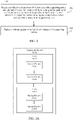
- FIG. 2 shows a flowchart 200 for rolling out updates to network-accessible server infrastructure 118, according to an example embodiment.
- flowchart 200 may be implemented by deployment orchestrator 136.
- FIG. 2 is described with continued reference to FIG. 1 .
- Other structural and operational embodiments will be apparent to persons skilled in the relevant art(s) based on the following discussion regarding flowchart 200 and system 100 of FIG. 1 .
- Flowchart 200 begins with step 202.
- an indication is received of a partition of the instances of the supporting service into a plurality of slices, each instance of the supporting service partitioned to include one or more slices of the plurality of slices, each slice of an instance of the supporting service including one or more of the service portions of the instance of the supporting service.
- deployment orchestrator 136 receives a partition indication 108 of the partitioning of supporting services of resource sets 106A-106N into a set of slices.
- Each slice includes one or more service portions of at least one instance of the instances of the supporting service and each instance of the supporting service includes one or more slices containing one or more service portions included in the instance. For instance, as shown in in FIG.
- supporting services 114A, 114N, 116A and 116N are each shown partitioned into slices 102A-102N (supporting services between supporting services 114A and 114N and between supporting services 116A and 116N are likewise sliced).
- Each of slices 102A-102N at a different one of supporting services 114A-114N and 116A-116N may include the same or different service portions as in another of supporting services 114A-116N.
- Partition indication 108 may be received in any manner, including being accessed from storage, such as in the form of a file, array, table, etc., that indicates the partitioning of slices 102A-102N (e.g., indicates identifiers for one or more of the servers, services, applications, etc., included in each slice of slices 102A-102N).
- the software update is deployed to the plurality of instances of the supporting service.
- deployment orchestrator 136 deploys software update deployment 125 to the supporting services of resource sets 106A-106N, including supporting services 114A-114N and 116A-116N.
- deployment orchestrator 136 deploys software update deployment 125 directly at the servers of resource sets 106A-106N.
- deployment orchestrator 136 transmits software update deployment 125 to agents at the servers of resource sets 106A-106N, and the agents in turn deploy software update deployment 125 to their respective servers of resource sets 106A-106N.
- the agents may be implemented in hardware, or hardware combined in one or both of software and firmware, and are configured to deploy software updates. Such agents may be present at the data center level, the cluster level, the rack level, or an agent may run in each server.
- a supporting service may be partitioned/sliced into multiple service portions.
- Each service portion includes one or more software/firmware components of the servers included in the slice, including cloud management code, operating systems (OS), virtual machines, storage device firmware, application services, etc.
- Each slice across a plurality of instances of the supporting service includes one or more of the service portions of each instance of the supporting service.
- FIG. 3A shows a block diagram of supporting service 114A of FIG. 1 , according to an example embodiment.
- Supporting service 114A includes (is formed by) service portions 310A-310N and 315A-315N (further service portions of supporting service 114A may not be shown in FIG. 3A for ease of illustration).
- Each of service portions 310A-310N and 315A-315N includes a corresponding portion (e.g., one or more components) of supporting service 114A.
- supporting service 114A is partitioned into exemplary slices 102A-102N.
- Each of slices 102A-102N includes one or more service portions (components) of supporting service 114A.
- slice 102A includes service portions 310A-310N, and slice 102N includes service portions 315A-315N. As such, each service portion is included in a single slice. Further instances of supporting service 114A (not shown in FIG. 3A ) may be partitioned by slices 102A-102N in a similar manner to supporting service 114A, or in different manners. For instance, slice 102A in each supporting service instance may include the same service portions or different service portions.
- FIG. 3B shows a block diagram of resource set 106A.
- resource set 106A includes a first server cluster 330A and a second server cluster 330B.
- Each of server clusters 330A and 330B hosts a corresponding instance of a supporting service A.
- server cluster 330A includes servers 335A, 335B, 335C, 335D, and 335E which include service A portions 355A, 355B, 355C, 355D, and 355E, respectively, making up a complete first instance of the supporting service A.
- cluster 330B includes servers 345A, 345B, 345C, 345D, and 345E which include service A portions 355A, 355B, 355C, 355D, and 355E, respectively, making up a complete second instance of supporting service A.
- Each instance of a supporting service is independent of other instances of the same supporting service.
- a software update rollout is performed sequentially from server to server in a resource set. For instance, in FIG. 3B , a software rollout may be rolled out in service cluster 330A beginning at server 335A, then to server 335B, and so on, finishing with server 335E. The software update may then be applied to servers 345A-345E in a similar manner.
- This conventional approach introduces problems, potentially including outages in multiple servers that host an instance of the supporting service in a server set, which may compromise operation of the supporting service in that server set.
- a software update rollout is performed sequentially from slice to slice, rather than server to server.
- the instance of service A defined by service A portions 355A-355E may be partitioned into first-fifth slices that respectively include service A portions 355A-355E in cluster 330A.
- the instance of service A defined by service A portions 355A-355E of cluster 330B may be similarly partitioned into those first-firth slices.
- the software update may be applied sequentially to the first-fifth slices one at a time, in the order of first to fifth slices.
- This slice-based update rollout enables controlled application of the software update to software/hardware in a desired sequence defined by the slices rather than merely applying the software update to servers sequentially.
- FIG. 3C shows an example of resource set 106A configured to receive software updates in slices, according to an exemplary embodiment.
- resource set 106A includes a first server cluster 302A, a second server cluster 302B, and a third server cluster 302C.
- a supporting service A that includes service A portions 312A-312C is deployed in each of server clusters 302A-302C.
- each of server clusters 302A, 302B, and 302C hosts a corresponding instance of supporting service A.
- Server cluster 302A includes supporting service A instance 332A
- server cluster 302B includes supporting service A instance 332B
- server cluster 302C includes supporting service A instance 332C.
- server cluster 302A includes servers 304A-304C, where servers 304A, 304B, and 304C include supporting service A portions 312A, 312B, and 312C, respectively, making up instance 332A.
- Cluster 302B includes servers 306A-306C, where servers 306A, 304B, and 306C include supporting service A portions 312A, 312B, and 312C, respectively, making up instance 332B.
- Cluster 302C includes servers 308A-308C, where servers 308A, 308B, and 308C include service A portion 312A, 312B, and 312C, respectively, making up instance 332C.
- each of instances 332A-332C includes all service portions of supporting service A.
- supporting service A may be sliced into first-third slices 375, 385, and 395.
- Slice 375 includes service A portion 312A in each of servers 304A, 306A, and 308A.
- Slice 385 includes service A portions 312B and 312C in servers 304B and 304C and service A portion 312C in server 308C.
- Slice 395 includes service A portions 312B and 312C in servers 306B and 306C and service A portion 312B in server 308B.
- service A portions 312A-312C of instances 332A-332C in server clusters 302A-302C are included in slices 375, 385, and 395, with each instance of a service portion being included in a single corresponding slice.
- a slice (e.g., first slice 375) may contain one or more same service portions (e.g., service A portion 312A) across all instances of the supporting service.
- a slice (e.g., slice 385) may contain one or more service portions (e.g. service A portion 312B and 312C) at a first instance of the supporting service (e.g., instance 332A) different from one or more service portions (e.g., service portion 312C) contained by the slice at a second instance of the supporting service (e.g., instance 332C).
- a same slice may contain different service portions at different instances of the supporting service.
- Updates may be applied to supporting service A on a slice-by-slice basis.
- a slice is updated, the service portions contained by that slice at the various instances of the supporting service are updated. For instance, in FIG. 3C , when slice 375 is updated, service A portion 312A in each of instances 332A-332C (in each of server clusters 302A-302C) is updated, while other service portions are not.
- slice 385 service A portions 312B and 312C in instance 332A (in server cluster 302A) and service A portion 312C (in server cluster 302C) are updated, while other service portions are not.
- service A portions 312B and 312C in instance 332B and service A portion 312B in instance 332C are updated, while other service portions are not.
- service portions in different instances of the supporting service hosted in different server sets (with corresponding hardware/software configurations), may be targeted for update in any desired sequence. This enables the simultaneous updating of the variety of hardware/software configurations contained in a slice, rather than merely updating servers sequentially (as in conventional systems).
- FIG. 4 shows a block diagram of a system 400 where software update deployment 125 is deployed by deployment orchestrator 136 to a supporting service set across servers 112A-112N, according to an embodiment.
- system 400 includes computing device(s) 104 and resource sets 106A-106N.
- Computing device(s) 104 includes deployment orchestrator 136, which includes an update sequencer 402, a service slicer 404, and an update bake timer 406.
- Resource set 106A includes servers 112A-112N
- resource set 106N includes servers 116A-116N (further resource sets are not shown for ease of illustration).
- Servers 112A includes supporting services 114A-114N and a health monitor 410.
- Servers 112B includes supporting services 116A-116N and a health monitor 415.
- Each of supporting services 114A-114N and 116A-116N includes slices 102A-102N.
- System 400 is described in further detail as follows.
- supporting services 114A-114N and 116A-116N are partitioned into a set of slices 102A-102N.
- service slicer 404 may be present. When present, service slicer 404 is configured to slice the supporting service into slices 102A-102N.
- service slicer 404 may slice supporting services 114A-116N into a plurality of slices, where each slice corresponds to a portion of the supporting service. These slices are independent portions of the supporting service from each other, such that if there is a problem, such as a failure, during deployment of the software update to a slice, the service portions included in the other slices maintain functionality.
- service slicer 404 slices the plurality of supporting services such that the slices increase in size in an order of a sequence of the slices.
- service slicer 404 slices the plurality of supporting services such that the slices are all of substantially equal size.
- service slicer 404 slices the plurality of supporting services such that the slices decrease in size in an order of the sequence.
- Service slicer 404 may update the slice slices dynamically.
- the supporting service can be divided into service portions such as stage, pilot, canary and broad, which may receive the software update in this order.
- Update sequencer 402 is configured to deploy software update 120 to the plurality of supporting services as software update deployment 125.
- update sequencer 402 deploys software update deployment 125 to slices 102A-102N of resource sets 106A-106N, including deploying software update deployment 125 to servers 112A of resource set 106A and servers 112N of resource set 106N.
- Update sequencer 402 deploys software update deployment 125 to slices 102A-102N in sequence such that the software update is applied to a same slice in parallel across the plurality of instances of the supporting service set before being applied to the next slice. For instance, as shown in FIG.
- software update deployment 125 is first deployed to slice 102A of each of supporting services 114A-114N and 116A-116N in parallel before being deployed to the next slice (i.e., slice 102B, implied but not explicitly shown in the figures). As long as software update deployment 125 does not have problems being deployed, update sequencer 402 continues to deploy software update deployment 125 to the remaining slices in sequence (e.g., slice 102C, slice 102D, etc., implied but not explicitly shown in the figures) until finally deployed to slice 102N.
- Update bake timer 406 is configured to cause update sequencer 402 to wait a wait time after applying the software update to a slice, before applying the software update to the next slice.
- update bake timer 406 enables update sequencer 402 to deploy software update deployment 125 to slice 102A, and causes update sequencer 402 to waits a wait time before enabling update sequencer 402 to deploy the software update to the next slice (i.e., slice 102B, implied but not explicitly shown in the figures).
- each wait time between slices is a same period of time.
- the wait time is dynamically updated, such that different wait times are waited between deployments of software update deployment 125 to slices. For example, in an embodiment, the wait time is decreased after each deployment of the software update to a slice of the supporting service instances. In still another embodiment, the wait time is set by the user.
- Monitoring may be used to determine failure or success of a deployment of a software update to servers on a slice-by-slice basis.
- health monitors may be present that are configured to generate health status signals.
- servers 112A includes health monitor 410 and servers 112N includes health monitor 415.
- Health monitors 410 and 415 dynamically transmit health signals 408A and 408N, respectively, for servers 112A and 112N to deployment orchestrator 136.
- Health monitors 410 and 416 may detect any number and type of problems related to servers 112A and 112N, respectively, including failures and/or other problems caused by the software update related to hardware (e.g., processor failures, node failures, storage failures, data transmitter/receiver failures, etc.), network failures (e.g., packet errors, network switch failures, etc.), software failures (e.g., virtual machine failures, OS failures, application failures), installation errors, uninstall errors, etc. Health status signals 408A and 408N may indicate any of these problems in corresponding error messages, warning messages, alerts, etc.
- hardware e.g., processor failures, node failures, storage failures, data transmitter/receiver failures, etc.
- network failures e.g., packet errors, network switch failures, etc.
- software failures e.g., virtual machine failures, OS failures, application failures
- installation errors uninstall errors, etc.
- deployment orchestrator 136 may receive a health status signal indicating one or more significant, including critical, problems
- software update deployment 125 may be delayed, terminated, and/or rolled back, and a user of computing device(s) may be alerted so that the problem(s) can be investigated.
- health status signals 408A and 408 may also indicate successful deployment of the software update to their respective resource sets.
- health monitor 410 and health monitor 415 are configured to monitor the slices for failures or other problem caused by the software update. For instance, as shown in FIG. 4 , after software update deployment 125 is deployed to both instances of slice 102A at servers 112A, the instances of slice 102A are continuously monitored by health monitor 410 at servers 112A to determine whether a failure or other problem occurs. Likewise, health monitor 415 monitors both instances of slice 102A at servers 112N after deployment of software update deployment 125. In an embodiment, a health monitor is configured to delay, terminate, and/or rollback the rollout of software update deployment 126 if a problem (i.e., a bad health signal) is detected, depending on the type and severity of the problem.
- a problem i.e., a bad health signal
- software update deployment 125 may be terminated as to further slices, and the affected component(s) of slice 102A may be investigated by the user. In this manner, problems with software updates may be pinpointed to a particular slice of the supporting service, and in particular, to specific software, firmware, and/or hardware.
- any number of health monitors may be present in a resource set, including one or more per resource set, per cluster, per rack, and/or per server.
- computing device(s) 104 receive health status signals, and if one or more problems with regard to the supporting service are indicated, may categorize each problem in into one of several categories, such as: complete failure of the supporting service, partial failure of the supporting service, delayed/latent complete failure of the supporting service, or delayed/latent partial failure of the supporting service.
- deployment orchestrator 136 deploys software updates to each of the instances of the supporting service, which may include any number of instances (e.g., in the tens, hundreds, thousands, etc.). As described above, the software update is deployed across the instances of the supporting service according to a sequence of slices, one slice being updated at a time, the same slice in all the supporting services being updated in parallel. Such deployment may be performed in any manner.
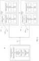
- FIG. 5 shows a flowchart 500 for deploying a software update in a sequence of slices, according to an example embodiment.
- Flowchart 500 may be implemented by deployment orchestrator 136 of FIGS. 1 and 4 , in embodiments.
- FIG. 5 is described as follows. Other structural and operational embodiments will be apparent to persons skilled in the relevant art(s) base on the following discussion regarding flowchart 500.
- Flowchart 500 begins with step 502.
- step 502 the application of the software update to the slices is sequenced such that the software update is applied to a same slice in parallel across the instances of the supporting service containing that same slice before being applied to a next slice, where at least a first applied slice in the sequence has substantially complete configuration diversity coverage of the network-accessible server infrastructure.
- update sequencer 402 sequences the deployment of software update deployment 125 across slices 102A-102N by first applying the update in parallel to each instance of slice 102A across all of the instances of the supporting service containing slice 102A. After the instances of slice 102A have been updated, software update deployment 125 may be applied to the next slice in a similar manner.
- Each slice in the sequence is updated in the order of the sequence, with slice 102N being the last slice to be updated in parallel across the supporting services.
- At least a first applied slice in the sequence has substantially complete configuration diversity coverage of network-accessible server infrastructure 118 ( FIG. 1 ).
- “Substantially complete configuration diversity coverage" for a slice means that the slice includes a sufficiently complete variety of resources of resource sets 106A-106N (e.g., servers, storage, etc.) in which the supporting service operates, such that when software update 120 is applied to the slice, at least one instance of any hardware device types, hardware device configurations, software configurations, and/or firmware configurations of the resources within resource sets 106A-106N receive software update 120.
- resource sets 106A-106N e.g., servers, storage, etc.
- the first slice of the sequence (slice 102A) is configured to have substantially complete configuration diversity coverage of resource sets 106A-106N.
- additional slices in the sequence of slices 102A-102N may be configured to have substantially complete configuration diversity coverage, including an embodiment where all of slices 102A-102N have substantially complete configuration diversity coverage.
- the complete configuration diversity of resource sets 106A-106N is tested at application of the update to each slice in the sequence.
- a wait time is waited after applying the software update to a slice of the plurality of slices before applying the software domain to a next slice of the plurality of slices in the sequence.
- update bake timer 406 of FIG. 4 is configured waits a wait time after software update deployment 125 is applied to the instances of slice 102A across supporting services 114A-114N and 116A-116N (and the other instances of the supporting service) before applying software update deployment 125 to a next slice.
- This wait time is used to allow the resources of slice 102A to operate with software update 120 applied, so that if there are problems (e.g., bugs, etc.) with software update 120, those problems will hopefully arise during the wait time, enabling further deployment of software update deployment 125 to be delayed, terminated, rolled back, etc., before being deployed to the next slice and potentially spreading the problems across further resources of network-accessible server infrastructure 118.
- problems e.g., bugs, etc.
- service slicer 404 may be present to slice the supporting service into slices that each include a corresponding portion of the service.
- FIG. 6 shows a flowchart 600 for forming slices, according to an example embodiment.
- flowchart 600 may be implemented by service slicer 404 of deployment orchestrator 136, as shown in FIG. 4 .
- Other structural and operational embodiments will be apparent to persons skilled in the relevant art(s) based on the following discussion regarding flowchart 600.
- Flowchart 600 begins with step 602.
- the instances of the supporting service are sliced into a plurality of slices.
- service slicer 404 slices the instances of the supporting service into slices 102A-102N. In this manner, software update deployment may be applied first to slice 102A before waiting a wait time and then being applied to a next slice, etc.
- service slicer 404 may be configured to slice the supporting service into the plurality of slices, such that one or more of the slices have substantially complete configuration diversity coverage.
- FIG. 7 shows a flowchart 700 for forming slices having substantially complete configuration diversity of a target network-accessible server platform, according to an example embodiment.
- flowchart 700 may be implemented by service slicer 404 of FIG. 4 .
- Other structural and operational embodiments will be apparent to persons skilled in the relevant art(s) based on the following discussion regarding flowchart 700.
- Flowchart 700 begins with step 702.
- the plurality of slices are configured to have substantially complete configuration diversity coverage.
- service slicer 404 may be configured to slice the supporting service into slices 102A-102N such that substantially complete configuration diversity coverage exists in one or more of the slices.
- service slicer 404 may inventory all hardware/software configurations of resources in network-accessible server infrastructure 118, and may include at least one instance of each hardware/software configuration (e.g., server model, processor configuration, OS version, etc.) in the slice.
- FIG. 8 shows a flowchart 800 for using changing wait times during a software update, according to an example embodiment.
- flowchart 800 may be implemented by update back timer 406, as shown in FIG. 4 .
- Other structural and operational embodiments will be apparent to persons skilled in the relevant art(s) based on the following discussion regarding flowchart 800.
- Flowchart 800 begins with step 802.
- the wait time is decreased for each iteration of said waiting after a first iteration of said waiting.
- update bake timer 406 may decrease the wait time after applying the software update to slice 102A before enabling software update deployment 125 to be applied to a next slice across supporting services 114A-114N and 116A-116N.
- the wait time may be decreased for some or all iterations of waiting before applying software update deployment 125 to a next slice. This reduction in wait times speeds up the overall application of the software update to all slices relative to continuing to use the original wait time after each application of the software update to the slices.
- the slices may be monitored for problems caused by the software update (e.g., due to bugs, coding errors, etc.).
- the deploying may be delayed, terminated, and/or rolled back.
- FIG. 9 shows a flowchart 900 for monitoring a software update for failures, according to an example embodiment.
- flowchart 900 may be implemented by update bake timer 406, as shown in FIG. 4 .
- Other structural and operational embodiments will be apparent to persons skilled in the relevant art(s) based on the following discussion regarding flowchart 900.
- Flowchart 900 begins with step 902.
- step 902 during the wait time following the applying of the software update to a slice, the slice is monitored for failures caused by the software update.
- update bake timer 406 of FIG. 4 may be configured to receive health signals from health monitors associated with resource sets 106A-106N, including health monitors 410 and 415, to determine if a problem caused by the software update occurs.
- health monitors 410 and 415 are configured to transmit health status signals 408A, 408N, respectively, related to resource sets 106A and 106B, respectively, to update bake timer 406.
- step 904 the deploying of the software update is terminated in response to a failure being determined during said monitoring. For example, if update bake timer 406 determines from a health status signal that a failure is caused by the software update, update bake timer 406 may instruct update sequencer 502 to delay or terminate further application of software update deployment 125, and optionally to rollback software update deployment 125 (e.g., uninstall) from one or more slices.
- update bake timer 406 may instruct update sequencer 502 to delay or terminate further application of software update deployment 125, and optionally to rollback software update deployment 125 (e.g., uninstall) from one or more slices.
- Computing device(s) 104, resource sets 106A-106N, servers 112A-112N, deployment orchestrator 136, computing devices 150, update sequencer 402, service slicer 404, update bake timer 406, health monitor 410, health monitor 415, flowchart 200, flowchart 500, flowchart 600, flowchart 700, flowchart 800, and flowchart 900 may be implemented in hardware, or hardware combined with software and/or firmware.
- deployment orchestrator 136, update sequencer 402, service slicer 404, update bake timer 406, health monitor 410, health monitor 415, flowchart 200, flowchart 500, flowchart 600, flowchart 700, flowchart 800, and/or flowchart 900 may be implemented as computer program code/instructions configured to be executed in one or more processors and stored in a computer readable storage medium.
- deployment orchestrator 136, update sequencer 402, service slicer 404, update bake timer 406, health monitor 410, health monitor 415, flowchart 200, flowchart 500, flowchart 600, flowchart 700, flowchart 800, and/or flowchart 900 may be implemented as hardware logic/electrical circuitry.
- one or more, in any combination, of deployment orchestrator 136, update sequencer 402, service slicer 404, update bake timer 406, health monitor 410, health monitor 415, flowchart 200, flowchart 500, flowchart 600, flowchart 700, flowchart 800, and/or flowchart 900 may be implemented together in a SoC.
- the SoC may include an integrated circuit chip that includes one or more of a processor (e.g., a central processing unit (CPU), microcontroller, microprocessor, digital signal processor (DSP), etc.), memory, one or more communication interfaces, and/or further circuits, and may optionally execute received program code and/or include embedded firmware to perform functions.
- a processor e.g., a central processing unit (CPU), microcontroller, microprocessor, digital signal processor (DSP), etc.
- memory e.g., a central processing unit (CPU), microcontroller, microprocessor, digital signal processor (DSP), etc.
- communication interfaces e.g
- FIG. 10 depicts an exemplary implementation of a computing device 1000 in which embodiments may be implemented.
- computing device(s) 140, computing devices 150, and/or servers 112A-112N may each be implemented in one or more computing devices similar to computing device 1000 in stationary or mobile computer embodiments, including one or more features of computing device 1000 and/or alternative features.
- the description of computing device 1000 provided herein is provided for purposes of illustration, and is not intended to be limiting. Embodiments may be implemented in further types of computer systems, as would be known to persons skilled in the relevant art(s).
- computing device 1000 includes one or more processors, referred to as processor circuit 1002, a system memory 1004, and a bus 1006 that couples various system components including system memory 1004 to processor circuit 1002.
- Processor circuit 1002 is an electrical and/or optical circuit implemented in one or more physical hardware electrical circuit device elements and/or integrated circuit devices (semiconductor material chips or dies) as a central processing unit (CPU), a microcontroller, a microprocessor, and/or other physical hardware processor circuit.
- Processor circuit 1002 may execute program code stored in a computer readable medium, such as program code of operating system 1030, application programs 1032, other programs 1034, etc.
- Bus 1006 represents one or more of any of several types of bus structures, including a memory bus or memory controller, a peripheral bus, an accelerated graphics port, and a processor or local bus using any of a variety of bus architectures.
- System memory 1004 includes read only memory (ROM) 1008 and random access memory (RAM) 1010.
- ROM read only memory
- RAM random access memory
- a basic input/output system 1012 (BIOS) is stored in ROM 1008.
- Computing device 1000 also has one or more of the following drives: a hard disk drive 1014 for reading from and writing to a hard disk, a magnetic disk drive 1016 for reading from or writing to a removable magnetic disk 1018, and an optical disk drive 1020 for reading from or writing to a removable optical disk 1022 such as a CD ROM, DVD ROM, or other optical media.
- Hard disk drive 1014, magnetic disk drive 1016, and optical disk drive 1020 are connected to bus 1006 by a hard disk drive interface 1024, a magnetic disk drive interface 1026, and an optical drive interface 1028, respectively.
- the drives and their associated computer-readable media provide nonvolatile storage of computer-readable instructions, data structures, program modules and other data for the computer.
- a hard disk, a removable magnetic disk and a removable optical disk are described, other types of hardware-based computer-readable storage media can be used to store data, such as flash memory cards, digital video disks, RAMs, ROMs, and other hardware storage media.
- a number of program modules may be stored on the hard disk, magnetic disk, optical disk, ROM, or RAM. These programs include operating system 1030, one or more application programs 1032, other programs 1034, and program data 1036.
- Application programs 1032 or other programs 1034 may include, for example, computer program logic (e.g., computer program code or instructions) for implementing deployment orchestrator 136, update sequencer 402, service slicer 404, update bake timer 406, health monitor 410, health monitor 415, flowchart 200, flowchart 500, flowchart 600, flowchart 700, flowchart 800, and/or flowchart 900 (including any suitable step of flowcharts 200, 500, 900), and/or further embodiments described herein.
- computer program logic e.g., computer program code or instructions
- a user may enter commands and information into the computing device 1000 through input devices such as keyboard 1038 and pointing device 1040.
- Other input devices may include a microphone, joystick, game pad, satellite dish, scanner, a touch screen and/or touch pad, a voice recognition system to receive voice input, a gesture recognition system to receive gesture input, or the like.
- processor circuit 1002 may be connected to processor circuit 1002 through a serial port interface 1042 that is coupled to bus 1006, but may be connected by other interfaces, such as a parallel port, game port, or a universal serial bus (USB).
- a display screen 1044 is also connected to bus 1006 via an interface, such as a video adapter 1046.
- Display screen 1044 may be external to, or incorporated in computing device 1000.
- Display screen 1044 may display information, as well as being a user interface for receiving user commands and/or other information (e.g., by touch, finger gestures, virtual keyboard, etc.).
- computing device 1000 may include other peripheral output devices (not shown) such as speakers and printers.
- Computing device 1000 is connected to a network 1048 (e.g., the Internet) through an adaptor or network interface 1050, a modem 1052, or other means for establishing communications over the network.
- Modem 1052 which may be internal or external, may be connected to bus 1006 via serial port interface 1042, as shown in FIG. 10 , or may be connected to bus 1006 using another interface type, including a parallel interface.
- computer program medium As used herein, the terms "computer program medium,” “computer-readable medium,” and “computer-readable storage medium” are used to refer to physical hardware media such as the hard disk associated with hard disk drive 1014, removable magnetic disk 1018, removable optical disk 1022, other physical hardware media such as RAMs, ROMs, flash memory cards, digital video disks, zip disks, MEMs, nanotechnology-based storage devices, and further types of physical/tangible hardware storage media.
- Such computer-readable storage media are distinguished from and non-overlapping with communication media (do not include communication media).
- Communication media embodies computer-readable instructions, data structures, program modules or other data in a modulated data signal such as a carrier wave.
- modulated data signal means a signal that has one or more of its characteristics set or changed in such a manner as to encode information in the signal.
- communication media includes wireless media such as acoustic, RF, infrared and other wireless media, as well as wired media.
- Embodiments are also directed to such communication media that are separate and non-overlapping with embodiments directed to computer-readable storage media.
- computer programs and modules may be stored on the hard disk, magnetic disk, optical disk, ROM, RAM, or other hardware storage medium. Such computer programs may also be received via network interface 1050, serial port interface 1042, or any other interface type. Such computer programs, when executed or loaded by an application, enable computing device 1000 to implement features of embodiments discussed herein. Accordingly, such computer programs represent controllers of the computing device 1000.
- Embodiments are also directed to computer program products comprising computer code or instructions stored on any computer-readable medium.
- Such computer program products include hard disk drives, optical disk drives, memory device packages, portable memory sticks, memory cards, and other types of physical storage hardware.
Landscapes
- Engineering & Computer Science (AREA)
- Theoretical Computer Science (AREA)
- Software Systems (AREA)
- General Engineering & Computer Science (AREA)
- Physics & Mathematics (AREA)
- General Physics & Mathematics (AREA)
- Computer Security & Cryptography (AREA)
- Mathematical Physics (AREA)
- Computer Networks & Wireless Communication (AREA)
- Signal Processing (AREA)
- Stored Programmes (AREA)
- Debugging And Monitoring (AREA)
- Information Transfer Between Computers (AREA)
Description
- The invention relates to rolling out of software updates in a network-accessible server infrastructure which operates multiple instances of a supporting service.
- Cloud computing is a form of network-accessible computing that provides shared computer processing resources and data to computers and other devices on demand over the Internet. Cloud computing enables the on-demand access to a shared pool of configurable computing resources, such as computer networks, servers, storage, applications, and services. The resources can be rapidly provisioned and released to a user with reduced management effort relative to the maintenance of local resources by the user. In some implementations, cloud computing and storage enables users, including enterprises, to store and process their data in third-party data centers that may be located far from the user, including distances that range from within a same city to across the world. The reliability of cloud computing is enhanced by the use of multiple redundant sites, where multiple copies of the same applications/services may be dispersed around different data centers (or other cloud computing sites), which enables safety in the form of disaster recovery when some cloud computing resources are damaged or otherwise fail.
- Cloud applications and platforms usually have some notion of fault isolation in them by segregating resources into logical divisions. Each logical division may a corresponding number and variety of resources, and may be duplicated at multiple sites. Such resources, such as servers, switches, and other computing devices that run software and/or firmware, may need to be periodically updated with the latest software/firmware. When dealing with a single service, the update strategy is relatively simple: update the service in isolation at one logical division to see if the changes work, then release the update to other logical divisions. The greater the number of services/applications needing to be updated, and the greater the number of different hardware configurations running the services/applications, the greater the deployment time of the updates.
US 2010/058318 A1 relates to rolling upgrades in distributed applications. Embodiments described therein are directed to updating the various software associated with a distributed application in a piecemeal fashion. All instances of the software are analyzed and separated into different portions, called "roles." Each instance of a role is strategically assigned to an update domain based on the structural information included in the service model of the distributed application. The distributed application is upgraded one update at a time by selecting an update or host update domain, bringing the roles assigned thereto offline, updating the offline roles, bringing the roles back online, and repeating for other update or host update domains. - It is the object of the present invention to provide improved methods, systems, and computer program products for rolling out updates to a network-accessible server infrastructure.
This object is solved by the subject matter of the independent claims.
Embodiments are defined by the dependent claims. - This Summary is provided to introduce a selection of concepts in a simplified form that are further described below in the Detailed Description. This Summary is not intended to identify key features or essential features of the claimed subject matter, nor is it intended to be used to limit the scope of the claimed subject matter.
- Methods, systems, and computer program products are provided for rolling out updates to a network-accessible server infrastructure which operates multiple instances (deployed copies) of a supporting service. The supporting service is defined by a plurality of service portions. Each instance of the supporting service includes the plurality of service portions. An indication of a partition of the instances of the supporting service into a plurality of slices is received. Each instance of the supporting service is partitioned to include one or more slices of the plurality of slices. Each slice of an instance of the supporting service includes one or more of the service portions of the instance of the supporting service.
- A software update can be deployed to the instances of the supporting service. The software update is deployed by applying the software update to the slices in a sequence such that the software update is applied to a same slice in parallel across the instances of the supporting service containing that same slice before being applied to a next slice. The first slice in the sequence has substantially complete configuration diversity coverage of the network-accessible server infrastructure (and further slices in the sequence may also have substantially complete coverage). A wait time is waited after each applying of the software update to a slice of the plurality of slices before applying the software domain to a next slice of the plurality of slices in the sequence.
- In this manner, the update can be applied to the network-accessible server infrastructure in an incremental manner, finding failures in the update early, confining such failures to a relatively limited portion of the infrastructure, with increasing confidence with each slice in the sequence that problems with the updated with be minimal. The update can be applied across the network-accessible server infrastructure relatively fast in his manner, including by enabling reduced wait times and/or the use of progressively larger slices.
- Further features and advantages of the invention, as well as the structure and operation of various embodiments, are described in detail below with reference to the accompanying drawings. It is noted that the embodiments are not limited to the specific embodiments described herein. Such embodiments are presented herein for illustrative purposes only. Additional embodiments will be apparent to persons skilled in the relevant art(s) based on the teachings contained herein.
- The accompanying drawings, which are incorporated herein and form a part of the specification, illustrate embodiments of the present application and, together with the description, further serve to explain the principles of the embodiments and to enable a person skilled in the pertinent art to make and use the embodiments.
-
FIG. 1 shows a block diagram of a system for rolling out updates to a network-accessible server infrastructure, according to an example embodiment. -
FIG. 2 shows a flowchart for rolling out updates to a network-accessible server infrastructure, according to an example embodiment. -
FIG. 3A shows a block diagram of a supporting service partitioned into slices that each include portions of the supporting service, according to an example embodiment. -
FIG. 3B shows a block diagram of a resource set in a system for rolling out updates to a network-accessible server infrastructure. -
FIG. 3C shows a block diagram of a resource set partitioned into slices, according to an example embodiment. -
FIG. 4 shows another block diagram of a system for rolling out updates to a network-accessible server infrastructure, according to an example embodiment. -
FIG. 5 shows a flowchart for deploying a software update across slices, according to an example embodiment. -
FIG. 6 shows a flowchart for forming slices, according to an example embodiment. -
FIG. 7 shows a flowchart for forming slices having substantially complete configuration diversity of a target network-accessible server platform, according to an example embodiment. -
FIG. 8 shows a flowchart for modifying wait times during a software update, according to an example embodiment. -
FIG. 9 shows a flowchart for monitoring a software update for failures, according to an example embodiment. -
FIG. 10 is a block diagram of an example processor-based computer system that may be used to implement various embodiments. - The features and advantages of the present invention will become more apparent from the detailed description set forth below when taken in conjunction with the drawings, in which like reference characters identify corresponding elements throughout. In the drawings, like reference numbers generally indicate identical, functionally similar, and/or structurally similar elements. The drawing in which an element first appears is indicated by the leftmost digit(s) in the corresponding reference number.
- The present specification and accompanying drawings disclose one or more embodiments that incorporate the features of the present invention. The scope of the present invention is not limited to the disclosed embodiments. The disclosed embodiments merely exemplify the present invention, and modified versions of the disclosed embodiments are also encompassed by the present invention. Embodiments of the present invention are defined by the claims appended hereto.
- References in the specification to "one embodiment," "an embodiment," "an example embodiment," etc., indicate that the embodiment described may include a particular feature, structure, or characteristic, but every embodiment may not necessarily include the particular feature, structure, or characteristic. Moreover, such phrases are not necessarily referring to the same embodiment. Further, when a particular feature, structure, or characteristic is described in connection with an embodiment, it is submitted that it is within the knowledge of one skilled in the art to effect such feature, structure, or characteristic in connection with other embodiments whether or not explicitly described.
- Furthermore, it should be understood that spatial descriptions (e.g., "above," "below," "up," "left," "right," "down," "top," "bottom," "vertical," "horizontal," etc.) used herein are for purposes of illustration only, and that practical implementations of the structures described herein can be spatially arranged in any orientation or manner.
- In the discussion, unless otherwise stated, adjectives such as "substantially" and "about" modifying a condition or relationship characteristic of a feature or features of an embodiment of the disclosure, are understood to mean that the condition or characteristic is defined to within tolerances that are acceptable for operation of the embodiment for an application for which it is intended.
- Numerous exemplary embodiments are described as follows. It is noted that any section/subsection headings provided herein are not intended to be limiting. Embodiments are described throughout this document, and any type of embodiment may be included under any section/subsection. Furthermore, embodiments disclosed in any section/subsection may be combined with any other embodiments described in the same section/subsection and/or a different section/subsection in any manner.
- Cloud computing is a form of network-accessible computing that provides shared computer processing resources and data to computers and other devices on demand over the Internet. Cloud computing enables the on-demand access to a shared pool of configurable computing resources, such as computer networks, servers, storage, applications, and services, which can be rapidly provisioned and released to a user with reduced management effort relative to the maintenance of local resources by the user.
- Cloud applications and platforms usually have some notion of fault isolation in them by segregating resources into logical divisions. Each logical division may a corresponding number and variety of resources, and may be duplicated at multiple sites. Such resources, such as servers, switches, and other computing devices that run software and/or firmware, may need to be periodically updated with the latest software/firmware. When dealing with a single service, the update strategy is relatively simple: update the service in isolation at one logical division to see if the changes work, then release the update to other logical divisions. The greater the number of services/applications needing to be updated, and the greater the number of different hardware configurations running the services/applications, the greater the deployment time of the updates.
- A cloud supporting service is defined herein as the service that manages the network-accessible server infrastructure. Examples of such a supporting service includes Microsoft® Azure®, Amazon Web Services™, Google Cloud Platform™, IBM® Smart Cloud, etc. The supporting service may be configured to build, deploy, and manage applications and services on the corresponding set of servers.
- There may be hundreds, thousands, or even greater numbers of instances of the cloud supporting services in operation in a large, worldwide platform of network-accessible servers. Typically, when deploying a software update to such a large number of instances of the supporting service, instead of deploying the software update to all instances in parallel (risking failure at a massive scale if the software update is flawed), the software update is applied to a series of groups of the instances of the supporting service, and time is given after each group to determine whether the updates succeeded. For instance, a first percentage (e.g., 1%) of the instances may be selected to first receive the update. If the update to the first percentage is successful, the update may be applied to a second percentage of the instances (e.g., 10%). If this succeeds, the update may be applied to a third percentage of the instances (e.g., 20%). then a fourth (30%), etc., until the update is applied to all of the instances. This way, any failures in the update may be isolated to a portion of the instances of the supporting service.
- Conventionally, the deployment time for each group of instances is kept constant, leading to a very long overall deployment time. Furthermore, the strategy of deploying the software update to groups of instances of the supporting service has increasing risk as the number of instances increases. For example, if there are 10,000 supporting services in operation, and the series of groups to which the update is applied are 100 instances, 1,000 instances, 4,000 instances, and lastly 4,900 instances, this means in the third phase, 4,000 services are updated - a large number of instances - and unless the all hardware/software configuration scenarios (for the servers running the instances of the supporting service) were completely covered in the earlier groups, there is a risk that the 4,000 services may each fail due to some unforeseen reason related to the software update.
- Embodiments overcome these issues by, instead of updating solely based on the number of services, defining a unit of supporting services referred to as a slice (also referred to as an "update domain", a partition, etc.). The supporting service is partitioned (sliced) into a sequence of slices, with the first slice, and optionally the subsequent slices in the sequence, having substantially complete configuration diversity coverage of all instances of the supporting services operating in the network-accessible server infrastructure. Instances of the same slice of the supporting service in a same server infrastructure can cover the same or different hardware in different sets of servers (e.g., a slice 1 on server cluster 1 may encompass a single server, while slice 1 on server cluster 2 may encompass two servers). Accordingly, the update of the slice in one cluster may update the corresponding service portion on different hardware than the update of the slice in another cluster. This approach has numerous advantages, including: hardware, software and configuration coverage across the entire fleet of supporting services; being scale free because each slice may have substantially complete configuration diversity coverage, and therefore the total rollout time depends on the configuration of the slices of slices across the supporting service, not on the number of instances of the supporting service in operation; longer bake time and shorter total rollout time, such that the number of slices (e.g., less than 20) is usually far less than the number of instances of the supporting services (e.g., greater than a thousand), and thus a longer bake time can be implemented between slices so that the probability to catch bugs is higher than regular approach. Furthermore, by rolling out software slice-by-slice, a high degree of coverage and parallelization is achieved (e.g., because each slice is updated in parallel across all instances of the slice). Still further, the total rollout time can be decreased because more bugs/problems in or caused by the software update can be captured in the early stage slices, and the overall rollout can be performed faster and safer as the software update deployment progresses. In embodiments, slices can adapt to new hardware and software configurations.
- Still further, a mechanism to safely and independently carry out the rollout of the software update without impacting multiple tenant customers in the worst case, can be to restrict the customer impact within a single tenant slice configured to have the highest probability to detect failures in the first slice. No customer/client code needs to be changed, in embodiments.
- In an embodiment, a slice definition, including a designation of which servers include in the slice, can be changed dynamically by a user (e.g., a release manager). Furthermore, a user can configure an order of the slice updates, a wait time for each update rollout to a slice, or both. In an embodiment, a slice is scale free and does not increase in size when the number of server clusters increases.
- Accordingly, embodiments provide the following (and additional) capabilities pertaining to software update rollouts in a cloud infrastructure: (1) A mechanism to safely and independently carry out the rollout of new features without impacting multiple tenant customers in the worst case; (2) A mechanism to restrict customer impact within a single tenant slice; (3) A mechanism to have relatively high probability of detecting any failures in the first slice to which the software update is applied; (4) A mechanism to keep reducing the probability of failure as the supporting service code executes in a different configuration; and (5) A scale-free mechanism to perform software update rollout with respect to cluster count.
- As follows, example embodiments are described herein directed to techniques for rolling out updates to a network-accessible server infrastructure. For instance,
FIG. 1 shows a block diagram of anexample system 100 for rolling out updates to a network-accessible server infrastructure, according to an example embodiment. As shown inFIG. 1 ,system 100 includes a plurality of resource sets 106A-106N, one ormore computing devices 140, andcomputing devices 150. Resource sets 106A-106N define a network-accessible server infrastructure 118. Resource sets 106A-106N, computing device(s) 140, andcomputing devices 150 are communicatively coupled via one ormore networks 110. Though computing device(s) 140 are shown separate from resource sets 106A-106N, in an embodiment, computing device(s) 140 may be included as node(s) in one or more of resource sets 106A-106N.Network 110 may comprise one or more networks such as local area networks (LANs), wide area networks (WANs), enterprise networks, the Internet, etc., and may include one or more of wired and/or wireless portions. In an embodiment, computing device(s) 140,computing devices 150, and each resource set of resource sets 106A-106N may communicate via one or more application programming interface (API). - Resource sets 106A-106N may form a network-accessible server set, such as a cloud computing server network. For example, each of resource sets 106A-106N may comprise a group or collection of servers (e.g., computing devices) that are each accessible by a network such as the Internet (e.g., in a "cloud-based" embodiment) to store, manage, and process data. Each of resource sets 106A-106N may comprise any number of servers, and may include any type and number of other resources, including resources that facilitate communications with and between the servers, storage by the servers, etc. (e.g., network switches, storage devices, networks, etc.). Servers of a resource set may be organized in any manner, including being grouped in server racks (e.g., 8-40 servers per rack, referred to as nodes or "blade servers"), server clusters (e.g., 2-64 servers, 4-8 racks, etc.), or datacenters (e.g., thousands of servers, hundreds of racks, dozens of clusters, etc.). In an embodiment, the servers of a resource set may be co-located (e.g., housed in one or more nearby buildings with associated components such as backup power supplies, redundant data communications, environmental controls, etc.) to form a datacenter, or may be arranged in other manners. Accordingly, in an embodiment, resource sets 106A-106N may each be a datacenter in a distributed collection of datacenters.
- Note that the variable "N" is appended to various reference numerals for illustrated components to indicate that the number of such components is variable, with any value of 2 and greater. Note that for each distinct component/reference numeral, the variable "N" has a corresponding value, which may be different for the value of "N" for other components/reference numerals. The value of "N" for any particular component/reference numeral may be less than 10, in the 10s, in the hundreds, in the thousands, or even greater, depending on the particular implementation.
- In accordance with such an embodiment, each of resource sets 106A-106N may be configured to service a particular geographical region. For example, resource set 106A may be configured to service the northeastern region of the United States, and resource set 106N may be configured to service the southwestern region of the United States. In another example, resource set 106A may be configured to service the northwestern region of the United States, and resource set 106N may be configured to service the southeastern region of the United States. It is noted that the network-accessible server set may include any number of resource sets, and each resource set may service any number of geographical regions worldwide.
- Each of the servers of resource sets 106A-106N may be configured to execute one or more services (including microservices), applications, and/or supporting services. In
FIG. 1 , one or more servers of resource set 106A may be configured to execute supportingservices 114A-114N, and one or more servers of resource set 106N may be configured to execute supportingservices 116A-116N. A "supporting service" is a cloud computing service/application configured to manage a set of servers (e.g., a cluster of servers) to operate as network-accessible (e.g., cloud-based) computing resources for users. Examples of supportingservices 114A-114N and 116A-116N include Microsoft® Azure®, Amazon Web Services™, Google Cloud Platform™, IBM® Smart Cloud, etc. A supporting service may be configured to build, deploy, and manage applications and services on the corresponding set of servers. Each instance of the supporting service may implement and/or manage a set of focused and distinct features or functions on the corresponding server set, including virtual machines, operating systems, application services, storage services, database services, messaging services, etc. Supporting services may be written in any programming language. - Each of the servers may be configured to execute any number of supporting service, including instances of the same supporting service. In an embodiment, if supporting
service 114N - Each supporting service may be divided, or sliced, into a plurality of slices. For instance, as shown in
FIG. 1 , supportingservice 114A is sliced intoslices 102A-102N. Likewise, supportingservices same slices 102A-102N as supportingservice 114A (supporting services between supportingservices services FIG. 1 for reasons of ease of illustration, are likewise sliced/partitioned). Though the servers may include many different hardware configurations (e.g., different configurations of servers, storage, processors, racks, etc.), and many different software configurations (e.g., different operating systems, etc.), each of supportingservices 114A-114N and 116A-116N may be sliced into the same plurality ofslices 102A-102N. However, this is not to be construed in a limiting sense and the instances of any supporting services can be sliced in any variation, so long as each service portion is included in a slice. For example, supportingservice 114A may includeslice 102A but not slice 102N, while supportingservice 114N may include both ofslices -
Computing devices 150 includes the computing devices of users (e.g., individual users, family users, enterprise users, governmental users, etc.) that access network-accessible resource sets 106A-106N for cloud computing resources throughnetwork 110.Computing devices 150 may include any number of computing devices, including tens, hundreds, thousands, millions, or even greater numbers of computing devices. Computing devices ofcomputing devices 150 may each be may be any type of stationary or mobile computing device, including a mobile computer or mobile computing device (e.g., a Microsoft ® Surface® device, a personal digital assistant (PDA), a laptop computer, a notebook computer, a tablet computer such as an Apple iPad™, a netbook, etc.), a mobile phone, a wearable computing device, or other type of mobile device, or a stationary computing device such as a desktop computer or PC (personal computer), or a server.Computing devices 150 may each interface with the servers through application programming interfaces (API)s and/or by other mechanisms. Note that any number of program interfaces may be present. - Computing device(s) 140 perform management functions for resource sets 106A-106N. For instance, as shown in
FIG. 1 , computing device(s) 140 includesdeployment orchestrator 136.Deployment orchestrator 136 is configured to manage the rolling out of updates to supportingservices 114A-114N, 116A-116N, etc., operating within resource sets 106A-106N.Deployment orchestrator 136 is configured to receive asoftware update 120 and manage the application ofsoftware update 120 to the supporting services of resource sets 106A-106N. For instance,deployment orchestrator 136 may transmitsoftware update deployment 125 in order to deploysoftware update 120 to the supporting services in resource sets 106A-106N. - Note that
software update 120 may include one or more updates to any number of software and/or firmware components of supportingservice 114A, including changes to existing software or firmware (e.g., updated versions), may include new software and/or firmware components for installation, and/or may designate one or more software and/or firmware components for uninstall. - Accordingly, in embodiments, software (which may include firmware) updates are rolled out to network-
accessible server infrastructure 118.Deployment orchestrator 136 may perform this rollout in various ways. For instance,FIG. 2 shows aflowchart 200 for rolling out updates to network-accessible server infrastructure 118, according to an example embodiment. In an embodiment,flowchart 200 may be implemented bydeployment orchestrator 136.FIG. 2 is described with continued reference toFIG. 1 . Other structural and operational embodiments will be apparent to persons skilled in the relevant art(s) based on the followingdiscussion regarding flowchart 200 andsystem 100 ofFIG. 1 . -
Flowchart 200 begins withstep 202. Instep 202, an indication is received of a partition of the instances of the supporting service into a plurality of slices, each instance of the supporting service partitioned to include one or more slices of the plurality of slices, each slice of an instance of the supporting service including one or more of the service portions of the instance of the supporting service. For example, with reference toFIG. 1 ,deployment orchestrator 136 receives apartition indication 108 of the partitioning of supporting services of resource sets 106A-106N into a set of slices. Each slice includes one or more service portions of at least one instance of the instances of the supporting service and each instance of the supporting service includes one or more slices containing one or more service portions included in the instance. For instance, as shown in inFIG. 1 , supportingservices slices 102A-102N (supporting services between supportingservices services slices 102A-102N at a different one of supportingservices 114A-114N and 116A-116N may include the same or different service portions as in another of supportingservices 114A-116N. -
Partition indication 108 may be received in any manner, including being accessed from storage, such as in the form of a file, array, table, etc., that indicates the partitioning ofslices 102A-102N (e.g., indicates identifiers for one or more of the servers, services, applications, etc., included in each slice ofslices 102A-102N). - In
step 204, the software update is deployed to the plurality of instances of the supporting service. For instance, with reference toFIG. 1 ,deployment orchestrator 136 deployssoftware update deployment 125 to the supporting services of resource sets 106A-106N, including supportingservices 114A-114N and 116A-116N. In one embodiment,deployment orchestrator 136 deployssoftware update deployment 125 directly at the servers of resource sets 106A-106N. In another embodiment,deployment orchestrator 136 transmitssoftware update deployment 125 to agents at the servers of resource sets 106A-106N, and the agents in turn deploysoftware update deployment 125 to their respective servers of resource sets 106A-106N. The agents may be implemented in hardware, or hardware combined in one or both of software and firmware, and are configured to deploy software updates. Such agents may be present at the data center level, the cluster level, the rack level, or an agent may run in each server. - A supporting service may be partitioned/sliced into multiple service portions. Each service portion includes one or more software/firmware components of the servers included in the slice, including cloud management code, operating systems (OS), virtual machines, storage device firmware, application services, etc. Each slice across a plurality of instances of the supporting service includes one or more of the service portions of each instance of the supporting service.
- For instance,
FIG. 3A shows a block diagram of supportingservice 114A ofFIG. 1 , according to an example embodiment. Supportingservice 114A includes (is formed by)service portions 310A-310N and 315A-315N (further service portions of supportingservice 114A may not be shown inFIG. 3A for ease of illustration). Each ofservice portions 310A-310N and 315A-315N includes a corresponding portion (e.g., one or more components) of supportingservice 114A. As shown inFIG. 3A , supportingservice 114A is partitioned intoexemplary slices 102A-102N. Each ofslices 102A-102N includes one or more service portions (components) of supportingservice 114A. For instance,slice 102A includesservice portions 310A-310N, andslice 102N includesservice portions 315A-315N. As such, each service portion is included in a single slice. Further instances of supportingservice 114A (not shown inFIG. 3A ) may be partitioned byslices 102A-102N in a similar manner to supportingservice 114A, or in different manners. For instance, slice 102A in each supporting service instance may include the same service portions or different service portions. - Furthermore, as described above, each particular slice may encompass the same or different hardware in different hosting server sets. For instance,
FIG. 3B shows a block diagram of resource set 106A. As shown inFIG. 3B , resource set 106A includes afirst server cluster 330A and asecond server cluster 330B. Each ofserver clusters FIG. 3B ,server cluster 330A includesservers service A portions cluster 330B includesservers service A portions - In conventional systems, a software update rollout is performed sequentially from server to server in a resource set. For instance, in
FIG. 3B , a software rollout may be rolled out inservice cluster 330A beginning atserver 335A, then to server 335B, and so on, finishing withserver 335E. The software update may then be applied toservers 345A-345E in a similar manner. This conventional approach introduces problems, potentially including outages in multiple servers that host an instance of the supporting service in a server set, which may compromise operation of the supporting service in that server set. - According to embodiments, a software update rollout is performed sequentially from slice to slice, rather than server to server. For instance, with respect to
FIG. 3B , the instance of service A defined byservice A portions 355A-355E may be partitioned into first-fifth slices that respectively includeservice A portions 355A-355E incluster 330A. The instance of service A defined byservice A portions 355A-355E ofcluster 330B may be similarly partitioned into those first-firth slices. In such an example, the software update may be applied sequentially to the first-fifth slices one at a time, in the order of first to fifth slices. This slice-based update rollout enables controlled application of the software update to software/hardware in a desired sequence defined by the slices rather than merely applying the software update to servers sequentially. - For instance,
FIG. 3C shows an example of resource set 106A configured to receive software updates in slices, according to an exemplary embodiment. As shown inFIG. 3C , resource set 106A includes afirst server cluster 302A, asecond server cluster 302B, and athird server cluster 302C. A supporting service A that includesservice A portions 312A-312C is deployed in each ofserver clusters 302A-302C. In particular, each ofserver clusters A. Server cluster 302A includes supporting service Ainstance 332A,server cluster 302B includes supporting service A instance 332B, andserver cluster 302C includes supportingservice A instance 332C. - As shown in
FIG. 3C ,server cluster 302A includes servers 304A-304C, where servers 304A, 304B, and 304C include supportingservice A portions instance 332A.Cluster 302B includes servers 306A-306C, whereservers 306A, 304B, and 306C include supportingservice A portions Cluster 302C includes servers 308A-308C, whereservers 308A, 308B, and 308C include service Aportion instance 332C. As such, each ofinstances 332A-332C includes all service portions of supporting service A. - In an embodiment, supporting service A may be sliced into first-
third slices Slice 375 includes service Aportion 312A in each of servers 304A, 306A, and 308A.Slice 385 includesservice A portions service A portion 312C inserver 308C.Slice 395 includesservice A portions servers 306B and 306C andservice A portion 312B in server 308B. As such,service A portions 312A-312C ofinstances 332A-332C inserver clusters 302A-302C are included inslices FIG. 3C , a slice (e.g., first slice 375) may contain one or more same service portions (e.g., service Aportion 312A) across all instances of the supporting service. Alternatively, a slice (e.g., slice 385) may contain one or more service portions (e.g.service A portion instance 332A) different from one or more service portions (e.g.,service portion 312C) contained by the slice at a second instance of the supporting service (e.g.,instance 332C). Thus, while every service portion of all supporting services is contained in a slice, a same slice may contain different service portions at different instances of the supporting service. - Updates may be applied to supporting service A on a slice-by-slice basis. When a slice is updated, the service portions contained by that slice at the various instances of the supporting service are updated. For instance, in
FIG. 3C , whenslice 375 is updated, service Aportion 312A in each ofinstances 332A-332C (in each ofserver clusters 302A-302C) is updated, while other service portions are not. Whenslice 385 is updated,service A portions instance 332A (inserver cluster 302A) andservice A portion 312C (inserver cluster 302C) are updated, while other service portions are not. Similarly, whenslice 395 is updated,service A portions service A portion 312B ininstance 332C (inserver clusters - Referring back to
FIG. 2 , step 204 may be performed in accordance with various embodiments. For instance,FIG. 4 shows a block diagram of asystem 400 wheresoftware update deployment 125 is deployed bydeployment orchestrator 136 to a supporting service set acrossservers 112A-112N, according to an embodiment. As shown inFIG. 4 ,system 400 includes computing device(s) 104 and resource sets 106A-106N. Computing device(s) 104 includesdeployment orchestrator 136, which includes anupdate sequencer 402, aservice slicer 404, and anupdate bake timer 406. Resource set 106A includesservers 112A-112N, resource set 106N includesservers 116A-116N (further resource sets are not shown for ease of illustration).Servers 112A includes supportingservices 114A-114N and ahealth monitor 410. Servers 112B includes supportingservices 116A-116N and ahealth monitor 415. Each of supportingservices 114A-114N and 116A-116N includesslices 102A-102N.System 400 is described in further detail as follows. - As described above, supporting
services 114A-114N and 116A-116N (and further instances of the supporting service not shown inFIG. 4 ) are partitioned into a set ofslices 102A-102N. In an embodiment,service slicer 404 may be present. When present,service slicer 404 is configured to slice the supporting service intoslices 102A-102N. - For instance, and as shown in
FIG. 4 ,service slicer 404 may slice supportingservices 114A-116N into a plurality of slices, where each slice corresponds to a portion of the supporting service. These slices are independent portions of the supporting service from each other, such that if there is a problem, such as a failure, during deployment of the software update to a slice, the service portions included in the other slices maintain functionality. In an embodiment,service slicer 404 slices the plurality of supporting services such that the slices increase in size in an order of a sequence of the slices. In another embodiment,service slicer 404 slices the plurality of supporting services such that the slices are all of substantially equal size. In still another embodiment,service slicer 404 slices the plurality of supporting services such that the slices decrease in size in an order of the sequence.Service slicer 404 may update the slice slices dynamically. In an embodiment, the supporting service can be divided into service portions such as stage, pilot, canary and broad, which may receive the software update in this order. -
Update sequencer 402 is configured to deploysoftware update 120 to the plurality of supporting services assoftware update deployment 125. In an embodiment, and as shown inFIG. 4 , updatesequencer 402 deployssoftware update deployment 125 toslices 102A-102N of resource sets 106A-106N, including deployingsoftware update deployment 125 toservers 112A of resource set 106A andservers 112N of resource set 106N.Update sequencer 402 deployssoftware update deployment 125 toslices 102A-102N in sequence such that the software update is applied to a same slice in parallel across the plurality of instances of the supporting service set before being applied to the next slice. For instance, as shown inFIG. 4 ,software update deployment 125 is first deployed to slice 102A of each of supportingservices 114A-114N and 116A-116N in parallel before being deployed to the next slice (i.e., slice 102B, implied but not explicitly shown in the figures). As long assoftware update deployment 125 does not have problems being deployed, updatesequencer 402 continues to deploysoftware update deployment 125 to the remaining slices in sequence (e.g., slice 102C, slice 102D, etc., implied but not explicitly shown in the figures) until finally deployed to slice 102N. -
Update bake timer 406 is configured to causeupdate sequencer 402 to wait a wait time after applying the software update to a slice, before applying the software update to the next slice. In an embodiment, and as shown inFIG. 4 , updatebake timer 406 enablesupdate sequencer 402 to deploysoftware update deployment 125 to slice 102A, and causesupdate sequencer 402 to waits a wait time before enablingupdate sequencer 402 to deploy the software update to the next slice (i.e., slice 102B, implied but not explicitly shown in the figures). In an embodiment, each wait time between slices is a same period of time. In another embodiment, the wait time is dynamically updated, such that different wait times are waited between deployments ofsoftware update deployment 125 to slices. For example, in an embodiment, the wait time is decreased after each deployment of the software update to a slice of the supporting service instances. In still another embodiment, the wait time is set by the user. - Monitoring may be used to determine failure or success of a deployment of a software update to servers on a slice-by-slice basis. In an embodiment, health monitors may be present that are configured to generate health status signals. For instance, and as shown in
FIG. 4 ,servers 112A includeshealth monitor 410 andservers 112N includeshealth monitor 415. Health monitors 410 and 415 dynamically transmithealth signals servers deployment orchestrator 136. Health monitors 410 and 416 may detect any number and type of problems related toservers deployment orchestrator 136 receives a health status signal indicating one or more significant, including critical, problems,software update deployment 125 may be delayed, terminated, and/or rolled back, and a user of computing device(s) may be alerted so that the problem(s) can be investigated. It is noted thathealth status signals 408A and 408 may also indicate successful deployment of the software update to their respective resource sets. - In an embodiment,
health monitor 410 and health monitor 415 are configured to monitor the slices for failures or other problem caused by the software update. For instance, as shown inFIG. 4 , aftersoftware update deployment 125 is deployed to both instances ofslice 102A atservers 112A, the instances ofslice 102A are continuously monitored byhealth monitor 410 atservers 112A to determine whether a failure or other problem occurs. Likewise,health monitor 415 monitors both instances ofslice 102A atservers 112N after deployment ofsoftware update deployment 125. In an embodiment, a health monitor is configured to delay, terminate, and/or rollback the rollout of software update deployment 126 if a problem (i.e., a bad health signal) is detected, depending on the type and severity of the problem. For instance, if a failure occurs whensoftware update deployment 125 is rolled out to the instances ofslice 102A,software update deployment 125 may be terminated as to further slices, and the affected component(s) ofslice 102A may be investigated by the user. In this manner, problems with software updates may be pinpointed to a particular slice of the supporting service, and in particular, to specific software, firmware, and/or hardware. - Note that any number of health monitors may be present in a resource set, including one or more per resource set, per cluster, per rack, and/or per server.
- In an embodiment, computing device(s) 104 receive health status signals, and if one or more problems with regard to the supporting service are indicated, may categorize each problem in into one of several categories, such as: complete failure of the supporting service, partial failure of the supporting service, delayed/latent complete failure of the supporting service, or delayed/latent partial failure of the supporting service.
- Accordingly, in embodiments,
deployment orchestrator 136 deploys software updates to each of the instances of the supporting service, which may include any number of instances (e.g., in the tens, hundreds, thousands, etc.). As described above, the software update is deployed across the instances of the supporting service according to a sequence of slices, one slice being updated at a time, the same slice in all the supporting services being updated in parallel. Such deployment may be performed in any manner. - For instance,
FIG. 5 shows aflowchart 500 for deploying a software update in a sequence of slices, according to an example embodiment.Flowchart 500 may be implemented bydeployment orchestrator 136 ofFIGS. 1 and4 , in embodiments.FIG. 5 is described as follows. Other structural and operational embodiments will be apparent to persons skilled in the relevant art(s) base on the followingdiscussion regarding flowchart 500. -
Flowchart 500 begins withstep 502. Instep 502, the application of the software update to the slices is sequenced such that the software update is applied to a same slice in parallel across the instances of the supporting service containing that same slice before being applied to a next slice, where at least a first applied slice in the sequence has substantially complete configuration diversity coverage of the network-accessible server infrastructure. For example, with reference toFIG. 4 , ifsoftware update deployment 125 is to be rolled out to each of supportingservices 114A-114N and 116A-116N, updatesequencer 402 sequences the deployment ofsoftware update deployment 125 acrossslices 102A-102N by first applying the update in parallel to each instance ofslice 102A across all of the instances of the supportingservice containing slice 102A. After the instances ofslice 102A have been updated,software update deployment 125 may be applied to the next slice in a similar manner. Each slice in the sequence is updated in the order of the sequence, withslice 102N being the last slice to be updated in parallel across the supporting services. - As indicated in
step 502, at least a first applied slice in the sequence has substantially complete configuration diversity coverage of network-accessible server infrastructure 118 (FIG. 1 ). "Substantially complete configuration diversity coverage" for a slice means that the slice includes a sufficiently complete variety of resources of resource sets 106A-106N (e.g., servers, storage, etc.) in which the supporting service operates, such that whensoftware update 120 is applied to the slice, at least one instance of any hardware device types, hardware device configurations, software configurations, and/or firmware configurations of the resources within resource sets 106A-106N receivesoftware update 120. In this manner,software update 120 is thoroughly tested just by being applied to a single slice, even though the slice may include a relatively small percentage of all of the resources of resource sets 106A-106N, because the slice completely covers the diversity of device configurations of resource sets 106A-106N. In other words, "substantially complete configuration diversity coverage" means the slice contains portions of the supporting service hosted by a substantially complete variety of the hardware/software configurations of resource sets 106A-106N defining the network-accessible server infrastructure. This enables thorough testing ofsoftware update 120 against this variety of hardware/software configurations of the network-accessible server infrastructure, so that if the software update is applied to the service portions of the supporting service in the slice with few to no significant problems cropping up, relatively high confidence may be gained that the software update can be applied against the service portions in the rest of the slices with relatively low probability of problems (enabling the software update to be applied to increasing larger slices and/or with decreasing wait times). - In an embodiment, the first slice of the sequence (slice 102A) is configured to have substantially complete configuration diversity coverage of resource sets 106A-106N. In further embodiments, additional slices in the sequence of
slices 102A-102N may be configured to have substantially complete configuration diversity coverage, including an embodiment where all ofslices 102A-102N have substantially complete configuration diversity coverage. In such an embodiment, the complete configuration diversity of resource sets 106A-106N is tested at application of the update to each slice in the sequence. - Referring back to
FIG. 5 , instep 504, a wait time is waited after applying the software update to a slice of the plurality of slices before applying the software domain to a next slice of the plurality of slices in the sequence. For example, updatebake timer 406 ofFIG. 4 is configured waits a wait time aftersoftware update deployment 125 is applied to the instances ofslice 102A across supportingservices 114A-114N and 116A-116N (and the other instances of the supporting service) before applyingsoftware update deployment 125 to a next slice. This wait time is used to allow the resources ofslice 102A to operate withsoftware update 120 applied, so that if there are problems (e.g., bugs, etc.) withsoftware update 120, those problems will hopefully arise during the wait time, enabling further deployment ofsoftware update deployment 125 to be delayed, terminated, rolled back, etc., before being deployed to the next slice and potentially spreading the problems across further resources of network-accessible server infrastructure 118. - As described above, in an embodiment,
service slicer 404 may be present to slice the supporting service into slices that each include a corresponding portion of the service. For instance,FIG. 6 shows aflowchart 600 for forming slices, according to an example embodiment. In an embodiment,flowchart 600 may be implemented byservice slicer 404 ofdeployment orchestrator 136, as shown inFIG. 4 . Other structural and operational embodiments will be apparent to persons skilled in the relevant art(s) based on the followingdiscussion regarding flowchart 600. -
Flowchart 600 begins withstep 602. Instep 602, the instances of the supporting service are sliced into a plurality of slices. For example, with reference toFIG. 4 , to prepare to roll outsoftware update deployment 125 to the instances of the supporting service,service slicer 404 slices the instances of the supporting service intoslices 102A-102N. In this manner, software update deployment may be applied first to slice 102A before waiting a wait time and then being applied to a next slice, etc. - In an embodiment,
service slicer 404 may be configured to slice the supporting service into the plurality of slices, such that one or more of the slices have substantially complete configuration diversity coverage. For instance,FIG. 7 shows aflowchart 700 for forming slices having substantially complete configuration diversity of a target network-accessible server platform, according to an example embodiment. In an embodiment,flowchart 700 may be implemented byservice slicer 404 ofFIG. 4 . Other structural and operational embodiments will be apparent to persons skilled in the relevant art(s) based on the followingdiscussion regarding flowchart 700. -
Flowchart 700 begins withstep 702. Instep 702, the plurality of slices are configured to have substantially complete configuration diversity coverage. For example, as shown inFIG. 4 ,service slicer 404 may be configured to slice the supporting service intoslices 102A-102N such that substantially complete configuration diversity coverage exists in one or more of the slices. For example, to generate a substantially complete configuration diversity coverage for a slice,service slicer 404 may inventory all hardware/software configurations of resources in network-accessible server infrastructure 118, and may include at least one instance of each hardware/software configuration (e.g., server model, processor configuration, OS version, etc.) in the slice. - As described above,
deployment orchestrator 136 waits a wait time after applying the software update to a slice before applying the software domain to a next slice in the sequence. In an embodiment, the wait time may be decreased for each iteration of waiting due to increasing confidence in the software update. For instance,FIG. 8 shows aflowchart 800 for using changing wait times during a software update, according to an example embodiment. In an embodiment,flowchart 800 may be implemented by update backtimer 406, as shown inFIG. 4 . Other structural and operational embodiments will be apparent to persons skilled in the relevant art(s) based on the followingdiscussion regarding flowchart 800. -
Flowchart 800 begins withstep 802. Instep 802, the wait time is decreased for each iteration of said waiting after a first iteration of said waiting. For example, updatebake timer 406 may decrease the wait time after applying the software update to slice 102A before enablingsoftware update deployment 125 to be applied to a next slice across supportingservices 114A-114N and 116A-116N. The wait time may be decreased for some or all iterations of waiting before applyingsoftware update deployment 125 to a next slice. This reduction in wait times speeds up the overall application of the software update to all slices relative to continuing to use the original wait time after each application of the software update to the slices. - In embodiments, the slices may be monitored for problems caused by the software update (e.g., due to bugs, coding errors, etc.). In response to a problem, the deploying may be delayed, terminated, and/or rolled back. For instance,
FIG. 9 shows aflowchart 900 for monitoring a software update for failures, according to an example embodiment. In an embodiment,flowchart 900 may be implemented byupdate bake timer 406, as shown inFIG. 4 . Other structural and operational embodiments will be apparent to persons skilled in the relevant art(s) based on the followingdiscussion regarding flowchart 900. -
Flowchart 900 begins withstep 902. Instep 902, during the wait time following the applying of the software update to a slice, the slice is monitored for failures caused by the software update. For example, updatebake timer 406 ofFIG. 4 may be configured to receive health signals from health monitors associated with resource sets 106A-106N, including health monitors 410 and 415, to determine if a problem caused by the software update occurs. As described above, health monitors 410 and 415 are configured to transmit health status signals 408A, 408N, respectively, related to resource sets 106A and 106B, respectively, to updatebake timer 406. - In
step 904, the deploying of the software update is terminated in response to a failure being determined during said monitoring. For example, ifupdate bake timer 406 determines from a health status signal that a failure is caused by the software update, updatebake timer 406 may instructupdate sequencer 502 to delay or terminate further application ofsoftware update deployment 125, and optionally to rollback software update deployment 125 (e.g., uninstall) from one or more slices. - Computing device(s) 104, resource sets 106A-106N,
servers 112A-112N,deployment orchestrator 136,computing devices 150, updatesequencer 402,service slicer 404,update bake timer 406,health monitor 410,health monitor 415,flowchart 200,flowchart 500,flowchart 600,flowchart 700,flowchart 800, andflowchart 900 may be implemented in hardware, or hardware combined with software and/or firmware. For example,deployment orchestrator 136, updatesequencer 402,service slicer 404,update bake timer 406,health monitor 410,health monitor 415,flowchart 200,flowchart 500,flowchart 600,flowchart 700,flowchart 800, and/orflowchart 900 may be implemented as computer program code/instructions configured to be executed in one or more processors and stored in a computer readable storage medium. Alternatively,deployment orchestrator 136, updatesequencer 402,service slicer 404,update bake timer 406,health monitor 410,health monitor 415,flowchart 200,flowchart 500,flowchart 600,flowchart 700,flowchart 800, and/orflowchart 900 may be implemented as hardware logic/electrical circuitry. - For instance, in an embodiment, one or more, in any combination, of
deployment orchestrator 136, updatesequencer 402,service slicer 404,update bake timer 406,health monitor 410,health monitor 415,flowchart 200,flowchart 500,flowchart 600,flowchart 700,flowchart 800, and/orflowchart 900 may be implemented together in a SoC. The SoC may include an integrated circuit chip that includes one or more of a processor (e.g., a central processing unit (CPU), microcontroller, microprocessor, digital signal processor (DSP), etc.), memory, one or more communication interfaces, and/or further circuits, and may optionally execute received program code and/or include embedded firmware to perform functions. -
FIG. 10 depicts an exemplary implementation of acomputing device 1000 in which embodiments may be implemented. For example, computing device(s) 140,computing devices 150, and/orservers 112A-112N may each be implemented in one or more computing devices similar tocomputing device 1000 in stationary or mobile computer embodiments, including one or more features ofcomputing device 1000 and/or alternative features. The description ofcomputing device 1000 provided herein is provided for purposes of illustration, and is not intended to be limiting. Embodiments may be implemented in further types of computer systems, as would be known to persons skilled in the relevant art(s). - As shown in
FIG. 10 ,computing device 1000 includes one or more processors, referred to as processor circuit 1002, asystem memory 1004, and abus 1006 that couples various system components includingsystem memory 1004 to processor circuit 1002. Processor circuit 1002 is an electrical and/or optical circuit implemented in one or more physical hardware electrical circuit device elements and/or integrated circuit devices (semiconductor material chips or dies) as a central processing unit (CPU), a microcontroller, a microprocessor, and/or other physical hardware processor circuit. Processor circuit 1002 may execute program code stored in a computer readable medium, such as program code ofoperating system 1030,application programs 1032,other programs 1034, etc.Bus 1006 represents one or more of any of several types of bus structures, including a memory bus or memory controller, a peripheral bus, an accelerated graphics port, and a processor or local bus using any of a variety of bus architectures.System memory 1004 includes read only memory (ROM) 1008 and random access memory (RAM) 1010. A basic input/output system 1012 (BIOS) is stored inROM 1008. -
Computing device 1000 also has one or more of the following drives: ahard disk drive 1014 for reading from and writing to a hard disk, amagnetic disk drive 1016 for reading from or writing to a removablemagnetic disk 1018, and anoptical disk drive 1020 for reading from or writing to a removableoptical disk 1022 such as a CD ROM, DVD ROM, or other optical media.Hard disk drive 1014,magnetic disk drive 1016, andoptical disk drive 1020 are connected tobus 1006 by a harddisk drive interface 1024, a magneticdisk drive interface 1026, and anoptical drive interface 1028, respectively. The drives and their associated computer-readable media provide nonvolatile storage of computer-readable instructions, data structures, program modules and other data for the computer. Although a hard disk, a removable magnetic disk and a removable optical disk are described, other types of hardware-based computer-readable storage media can be used to store data, such as flash memory cards, digital video disks, RAMs, ROMs, and other hardware storage media. - A number of program modules may be stored on the hard disk, magnetic disk, optical disk, ROM, or RAM. These programs include
operating system 1030, one ormore application programs 1032,other programs 1034, andprogram data 1036.Application programs 1032 orother programs 1034 may include, for example, computer program logic (e.g., computer program code or instructions) for implementingdeployment orchestrator 136, updatesequencer 402,service slicer 404,update bake timer 406,health monitor 410,health monitor 415,flowchart 200,flowchart 500,flowchart 600,flowchart 700,flowchart 800, and/or flowchart 900 (including any suitable step offlowcharts - A user may enter commands and information into the
computing device 1000 through input devices such askeyboard 1038 andpointing device 1040. Other input devices (not shown) may include a microphone, joystick, game pad, satellite dish, scanner, a touch screen and/or touch pad, a voice recognition system to receive voice input, a gesture recognition system to receive gesture input, or the like. These and other input devices are often connected to processor circuit 1002 through aserial port interface 1042 that is coupled tobus 1006, but may be connected by other interfaces, such as a parallel port, game port, or a universal serial bus (USB). - A
display screen 1044 is also connected tobus 1006 via an interface, such as a video adapter 1046.Display screen 1044 may be external to, or incorporated incomputing device 1000.Display screen 1044 may display information, as well as being a user interface for receiving user commands and/or other information (e.g., by touch, finger gestures, virtual keyboard, etc.). In addition todisplay screen 1044,computing device 1000 may include other peripheral output devices (not shown) such as speakers and printers. -
Computing device 1000 is connected to a network 1048 (e.g., the Internet) through an adaptor ornetwork interface 1050, amodem 1052, or other means for establishing communications over the network.Modem 1052, which may be internal or external, may be connected tobus 1006 viaserial port interface 1042, as shown inFIG. 10 , or may be connected tobus 1006 using another interface type, including a parallel interface. - As used herein, the terms "computer program medium," "computer-readable medium," and "computer-readable storage medium" are used to refer to physical hardware media such as the hard disk associated with
hard disk drive 1014, removablemagnetic disk 1018, removableoptical disk 1022, other physical hardware media such as RAMs, ROMs, flash memory cards, digital video disks, zip disks, MEMs, nanotechnology-based storage devices, and further types of physical/tangible hardware storage media. Such computer-readable storage media are distinguished from and non-overlapping with communication media (do not include communication media). Communication media embodies computer-readable instructions, data structures, program modules or other data in a modulated data signal such as a carrier wave. The term "modulated data signal" means a signal that has one or more of its characteristics set or changed in such a manner as to encode information in the signal. By way of example, and not limitation, communication media includes wireless media such as acoustic, RF, infrared and other wireless media, as well as wired media. Embodiments are also directed to such communication media that are separate and non-overlapping with embodiments directed to computer-readable storage media. - As noted above, computer programs and modules (including
application programs 1032 and other programs 1034) may be stored on the hard disk, magnetic disk, optical disk, ROM, RAM, or other hardware storage medium. Such computer programs may also be received vianetwork interface 1050,serial port interface 1042, or any other interface type. Such computer programs, when executed or loaded by an application, enablecomputing device 1000 to implement features of embodiments discussed herein. Accordingly, such computer programs represent controllers of thecomputing device 1000. - Embodiments are also directed to computer program products comprising computer code or instructions stored on any computer-readable medium. Such computer program products include hard disk drives, optical disk drives, memory device packages, portable memory sticks, memory cards, and other types of physical storage hardware.
- While various embodiments of the present invention have been described above, it should be understood that they have been presented by way of example only, and not limitation. It will be understood by those skilled in the relevant art(s) that various changes in form and details may be made therein.
- Accordingly, the scope of the present invention should not be limited by any of the above-described exemplary embodiments, but should be defined only in accordance with the following claims.
Claims (13)
- A method of rolling out updates to a network-accessible server infrastructure which operates a plurality of instances of a supporting service, the supporting service comprised by a plurality of service portions, the instances of the supporting service each including the plurality of service portions, the method comprising:receiving (202) an indication of a partition of the instances of the supporting service into a plurality of slices, each instance of the supporting service partitioned to include one or more slices of the plurality of slices, each slice of an instance of the supporting service including one or more of the service portions of the instance of the supporting service; anddeploying (204) a software update to the plurality of instances of the supporting service by applying the software update to the plurality of slices in a sequence such that the software update is applied to a same slice in parallel across the instances of the supporting service containing that same slice before being applied to a next slice, at least a first applied slice in the sequence having complete configuration diversity coverage of the network-accessible server infrastructure,characterized in thatdeploying (204) the software update to the plurality of instances of the supporting service further comprises waiting a wait time after each applying of the software update to a slice of the plurality of slices before applying the software update to a next slice of the plurality of slices in the sequence, andin a first instance of the instances of the supporting service, a first slice of the plurality of slices includes a first set of the service portions, and in a second instance of the instances of the supporting service, the first slice of the plurality of slices includes a second set of the service portions that is different from the first set of the service portions.
- The method of claim 1, wherein all slices of the plurality of slices have complete configuration diversity coverage of the network-accessible server infrastructure.
- The method of claim 2, wherein the complete configuration diversity coverage of the network-accessible server infrastructure includes at least one of:complete configuration diversity coverage of server hardware configurations included in the network-accessible server infrastructure, orcomplete configuration diversity coverage of server software configurations included in the network-accessible server infrastructure.
- The method of claim 1, further comprising:
slicing the instances of the supporting service into the plurality of slices such that the slices increase in size in the sequence. - The method of claim 1, wherein said waiting comprises:
decreasing the wait time for each iteration of said waiting after a first iteration of said waiting. - The method of claim 1, wherein said waiting comprises:during the wait time following the applying of the software update to a slice, monitoring the slice for failures caused by the software update; andin response to the determination of a failure during said monitoring, terminating said deploying of the software update.
- A system, comprising:at least one processor circuit; andat least one memory that stores program code configured to be executed by the at least one processor circuit, the program code comprising:a deployment orchestrator (136) configured to roll out updates in a network- accessible server infrastructure which operates a plurality of instances of a supporting service, the supporting service comprised by a plurality of service portions (312 A, 312B, 312C), the instances of the supporting service each including the plurality of service portions, the deployment orchestrator (136) configured toreceive an indication of a partition of the instances (114A, 114N, 116A, 116N) of the supporting service into a plurality of slices (102 A, ..., 102N), each instance (114A, 114N, 116A, 116N) of the supporting service partitioned to include one or more slices of the plurality of slices (102A, ... , 102N),each slice of an instance of the supporting service including one or more of the service portions (312 A, 312B, 312C) of the instance of the supporting service, anddeploy a software update to the plurality of instances (114A, 114N, 116A, 116N) of the supporting service, the deployment orchestrator including
an update sequencer (402) configured to apply the software update to the slices in a sequence such that the software update is applied to a same slice in parallel across the instances of the supporting service containing that same slice before being applied to a next slice, at least a first applied slice in the sequence has complete configuration diversity coverage of the network-accessible server infrastructure,characterized in thatthe deployment orchestrator further comprises an update bake timer (406) configured to enact a wait time after each applying of the software update to a slice of the plurality of slices (102A, ... , 102N) by the update sequencer (402) before enabling the update sequencer (402) to apply the software update to a next slice of the plurality of slices in the sequence, andin a first instance of the instances of the supporting service, a first slice of the plurality of slices includes a first set of the service portions, and in a second instance of the instances of the supporting service, the first slice of the plurality of slices includes a second set of the service portions that is different from the first set of the service portions. - The system of claim 7, wherein all slices of the plurality of slices have complete configuration diversity coverage of the network-accessible server infrastructure.
- The system of claim 7, wherein the complete configuration diversity coverage of the network-accessible server infrastructure includes at least one of:complete configuration diversity coverage of server hardware configurations included in the network-accessible server infrastructure, orcomplete configuration diversity coverage of server software configurations included in the network-accessible server infrastructure.
- The system of claim 7, wherein the deployment orchestrator (136) further comprises: a server slicer (404) configured to slice the instances of the supporting service into the plurality of slices such that the slices increase in size in the sequence.
- The system of claim 7, wherein the update bake timer (406) is further configured to decrease the wait time for each enacting of the wait time subsequent to a first enactment of the wait time.
- The system of claim 7, wherein the update bake timer (406) is further configured to:receive an indication of the failure caused by the software update; andterminate the deploying of the software update if an indication of the failure caused by the software update is received.
- A computer-readable storage medium having program instructions recorded thereon, which, when executed by a computer, cause the computer to carry out any of the methodsof claims 1-6.
Applications Claiming Priority (2)
| Application Number | Priority Date | Filing Date | Title |
|---|---|---|---|
| US15/635,084 US10191731B2 (en) | 2017-06-27 | 2017-06-27 | Safe and agile rollouts in a network-accessible server infrastructure using slices |
| PCT/US2018/035239 WO2019005398A1 (en) | 2017-06-27 | 2018-05-31 | Safe and agile rollouts in a network-accessible server infrastructure using slices |
Publications (2)
| Publication Number | Publication Date |
|---|---|
| EP3646167A1 EP3646167A1 (en) | 2020-05-06 |
| EP3646167B1 true EP3646167B1 (en) | 2023-04-05 |
Family
ID=62751548
Family Applications (1)
| Application Number | Title | Priority Date | Filing Date |
|---|---|---|---|
| EP18734680.4A Active EP3646167B1 (en) | 2017-06-27 | 2018-05-31 | Safe and agile rollouts in a network-accessible server infrastructure using slices |
Country Status (3)
| Country | Link |
|---|---|
| US (2) | US10191731B2 (en) |
| EP (1) | EP3646167B1 (en) |
| WO (1) | WO2019005398A1 (en) |
Families Citing this family (10)
| Publication number | Priority date | Publication date | Assignee | Title |
|---|---|---|---|---|
| US10191731B2 (en) * | 2017-06-27 | 2019-01-29 | Microsoft Technology Licensing, Llc | Safe and agile rollouts in a network-accessible server infrastructure using slices |
| US10360012B2 (en) * | 2017-11-09 | 2019-07-23 | International Business Machines Corporation | Dynamic selection of deployment configurations of software applications |
| US11412041B2 (en) | 2018-06-25 | 2022-08-09 | International Business Machines Corporation | Automatic intervention of global coordinator |
| US10915380B2 (en) * | 2018-07-16 | 2021-02-09 | International Business Machines Corporation | Global coordination of in-progress operation risks for multiple distributed storage network memories |
| US11294654B2 (en) * | 2020-05-20 | 2022-04-05 | Microsoft Technology Licensing, Llc | Automated rules for controlled distribution of program instructions |
| CN114553692A (en) * | 2020-11-25 | 2022-05-27 | 中兴通讯股份有限公司 | Method and device for upgrading network slice |
| EP4587925A1 (en) * | 2022-09-16 | 2025-07-23 | Oracle International Corporation | Remote data planes for virtual private label clouds |
| US20240126531A1 (en) * | 2022-10-14 | 2024-04-18 | Oracle International Corporation | Single node rolling online patching of a database server |
| US12271729B2 (en) * | 2023-02-28 | 2025-04-08 | Gm Cruise Holdings Llc | Progressive delivery of cluster infrastructure updates |
| US12511112B2 (en) | 2023-03-28 | 2025-12-30 | Microsoft Technology Licensing, Llc | Automated update management for cloud services |
Family Cites Families (21)
| Publication number | Priority date | Publication date | Assignee | Title |
|---|---|---|---|---|
| US6606744B1 (en) * | 1999-11-22 | 2003-08-12 | Accenture, Llp | Providing collaborative installation management in a network-based supply chain environment |
| US8839221B2 (en) | 2007-09-10 | 2014-09-16 | Moka5, Inc. | Automatic acquisition and installation of software upgrades for collections of virtual machines |
| US20090144720A1 (en) | 2007-11-30 | 2009-06-04 | Sun Microsystems, Inc. | Cluster software upgrades |
| US8266260B2 (en) * | 2007-12-11 | 2012-09-11 | Sharp Laboratories Of America, Inc. | Method and system for updating the software of multiple network nodes |
| US10411975B2 (en) * | 2013-03-15 | 2019-09-10 | Csc Agility Platform, Inc. | System and method for a cloud computing abstraction with multi-tier deployment policy |
| US9069599B2 (en) * | 2008-06-19 | 2015-06-30 | Servicemesh, Inc. | System and method for a cloud computing abstraction layer with security zone facilities |
| US8375383B2 (en) | 2008-08-28 | 2013-02-12 | Microsoft Corporation | Rolling upgrades in distributed applications |
| US9229707B2 (en) * | 2008-12-18 | 2016-01-05 | Sap Se | Zero downtime mechanism for software upgrade of a distributed computer system |
| US8516477B1 (en) * | 2010-03-12 | 2013-08-20 | Cellco Partnership | Automated deployment tool for multiple server environment |
| US9134992B2 (en) | 2011-08-31 | 2015-09-15 | Vmware, Inc. | Interactive and visual planning tool for managing installs and upgrades |
| US8935375B2 (en) | 2011-12-12 | 2015-01-13 | Microsoft Corporation | Increasing availability of stateful applications |
| US8782632B1 (en) * | 2012-06-18 | 2014-07-15 | Tellabs Operations, Inc. | Methods and apparatus for performing in-service software upgrade for a network device using system virtualization |
| US20140033188A1 (en) | 2012-07-26 | 2014-01-30 | Microsoft Corporation | System updates from cloud blob storage using vhd differentials |
| US9419859B2 (en) | 2012-12-04 | 2016-08-16 | Microsoft Technology Licensing, Llc | Service allocation in a distributed computing platform |
| US9459856B2 (en) | 2013-01-02 | 2016-10-04 | International Business Machines Corporation | Effective migration and upgrade of virtual machines in cloud environments |
| US9141373B2 (en) | 2013-07-31 | 2015-09-22 | Arista Networks, Inc. | System and method for accelerated software upgrades |
| US9558093B2 (en) | 2014-07-30 | 2017-01-31 | Microsoft Technology Licensing, Llc | Visual tools for failure analysis in distributed systems |
| US9262152B1 (en) | 2015-01-22 | 2016-02-16 | Bank Of America Corporation | Modular system including management and deployment of software updates and revisions |
| US9729421B2 (en) * | 2015-03-25 | 2017-08-08 | International Business Machines Corporation | Outcome-based software-defined infrastructure |
| DE102015224950A1 (en) * | 2015-12-11 | 2017-06-14 | Airbus Operations Gmbh | Technology for updating software on board an aircraft |
| US10191731B2 (en) * | 2017-06-27 | 2019-01-29 | Microsoft Technology Licensing, Llc | Safe and agile rollouts in a network-accessible server infrastructure using slices |
-
2017
- 2017-06-27 US US15/635,084 patent/US10191731B2/en active Active
-
2018
- 2018-05-31 WO PCT/US2018/035239 patent/WO2019005398A1/en not_active Ceased
- 2018-05-31 EP EP18734680.4A patent/EP3646167B1/en active Active
- 2018-12-13 US US16/219,087 patent/US10740086B2/en active Active
Also Published As
| Publication number | Publication date |
|---|---|
| US20190250901A1 (en) | 2019-08-15 |
| US10191731B2 (en) | 2019-01-29 |
| US10740086B2 (en) | 2020-08-11 |
| EP3646167A1 (en) | 2020-05-06 |
| US20180373521A1 (en) | 2018-12-27 |
| WO2019005398A1 (en) | 2019-01-03 |
Similar Documents
| Publication | Publication Date | Title |
|---|---|---|
| US10740086B2 (en) | Safe and agile rollouts in a network-accessible server infrastructure using slices | |
| EP3834392B1 (en) | Malicious cloud-based resource allocation detection | |
| US10601682B2 (en) | Service availability management method, service availability management apparatus, and network function virtualization architecture thereof | |
| US10191820B2 (en) | Virtual proxy based backup | |
| EP2972870B1 (en) | Coordinating fault recovery in a distributed system | |
| US10581897B1 (en) | Method and system for implementing threat intelligence as a service | |
| US10447525B2 (en) | Validating correlation between chains of alerts using cloud view | |
| EP2630567B1 (en) | Coordinated upgrades in distributed systems | |
| US9652332B2 (en) | Information processing apparatus and virtual machine migration method | |
| US10678581B2 (en) | Methods and apparatus to select virtualization environments during deployment | |
| EP3646568B1 (en) | Determining an optimal timeout value to minimize downtime for nodes in a network-accessible server set | |
| US10476742B1 (en) | Classification of auto scaling events impacting computing resources | |
| US9703652B2 (en) | VM and host management function availability during management network failure in host computing systems in a failover cluster | |
| US20180331973A1 (en) | Increasing virtual machine availability during server updates | |
| EP3522018B1 (en) | Identification of a soft failure at a member | |
| US20200244766A1 (en) | Systems and methods for semi-automatic workload domain deployments | |
| US20130083030A1 (en) | Display control apparatus, display control method, and recording medium storing display control program | |
| US12236269B2 (en) | Distribution of workloads in cluster environment using server warranty information | |
| US10904113B2 (en) | Insight ranking based on detected time-series changes | |
| US20220334860A1 (en) | Automated Storage System Performance Validation | |
| US12126489B2 (en) | System, method, and computer program for managing deployment of network element | |
| US12547527B2 (en) | Intelligent customer service request processing mechanism | |
| CN119829414A (en) | Intelligent use case execution priority assessment mechanism | |
| US12095643B1 (en) | Event publication from compute nodes installed in a chassis of a modular server to a console of the chassis | |
| US12632362B2 (en) | Method to detecting infinite loops in real-time logs from a continuous integration environment |
Legal Events
| Date | Code | Title | Description |
|---|---|---|---|
| STAA | Information on the status of an ep patent application or granted ep patent |
Free format text: STATUS: UNKNOWN |
|
| STAA | Information on the status of an ep patent application or granted ep patent |
Free format text: STATUS: THE INTERNATIONAL PUBLICATION HAS BEEN MADE |
|
| PUAI | Public reference made under article 153(3) epc to a published international application that has entered the european phase |
Free format text: ORIGINAL CODE: 0009012 |
|
| STAA | Information on the status of an ep patent application or granted ep patent |
Free format text: STATUS: REQUEST FOR EXAMINATION WAS MADE |
|
| 17P | Request for examination filed |
Effective date: 20191211 |
|
| AK | Designated contracting states |
Kind code of ref document: A1 Designated state(s): AL AT BE BG CH CY CZ DE DK EE ES FI FR GB GR HR HU IE IS IT LI LT LU LV MC MK MT NL NO PL PT RO RS SE SI SK SM TR |
|
| AX | Request for extension of the european patent |
Extension state: BA ME |
|
| DAV | Request for validation of the european patent (deleted) | ||
| DAX | Request for extension of the european patent (deleted) | ||
| RAP3 | Party data changed (applicant data changed or rights of an application transferred) |
Owner name: MICROSOFT TECHNOLOGY LICENSING, LLC |
|
| STAA | Information on the status of an ep patent application or granted ep patent |
Free format text: STATUS: EXAMINATION IS IN PROGRESS |
|
| 17Q | First examination report despatched |
Effective date: 20211118 |
|
| GRAP | Despatch of communication of intention to grant a patent |
Free format text: ORIGINAL CODE: EPIDOSNIGR1 |
|
| STAA | Information on the status of an ep patent application or granted ep patent |
Free format text: STATUS: GRANT OF PATENT IS INTENDED |
|
| INTG | Intention to grant announced |
Effective date: 20221121 |
|
| GRAS | Grant fee paid |
Free format text: ORIGINAL CODE: EPIDOSNIGR3 |
|
| GRAA | (expected) grant |
Free format text: ORIGINAL CODE: 0009210 |
|
| STAA | Information on the status of an ep patent application or granted ep patent |
Free format text: STATUS: THE PATENT HAS BEEN GRANTED |
|
| AK | Designated contracting states |
Kind code of ref document: B1 Designated state(s): AL AT BE BG CH CY CZ DE DK EE ES FI FR GB GR HR HU IE IS IT LI LT LU LV MC MK MT NL NO PL PT RO RS SE SI SK SM TR |
|
| REG | Reference to a national code |
Ref country code: GB Ref legal event code: FG4D |
|
| REG | Reference to a national code |
Ref country code: DE Ref legal event code: R096 Ref document number: 602018048044 Country of ref document: DE |
|
| REG | Reference to a national code |
Ref country code: CH Ref legal event code: EP |
|
| REG | Reference to a national code |
Ref country code: AT Ref legal event code: REF Ref document number: 1558758 Country of ref document: AT Kind code of ref document: T Effective date: 20230415 |
|
| REG | Reference to a national code |
Ref country code: IE Ref legal event code: FG4D |
|
| P01 | Opt-out of the competence of the unified patent court (upc) registered |
Effective date: 20230505 |
|
| REG | Reference to a national code |
Ref country code: LT Ref legal event code: MG9D |
|
| REG | Reference to a national code |
Ref country code: NL Ref legal event code: MP Effective date: 20230405 |
|
| REG | Reference to a national code |
Ref country code: AT Ref legal event code: MK05 Ref document number: 1558758 Country of ref document: AT Kind code of ref document: T Effective date: 20230405 |
|
| PG25 | Lapsed in a contracting state [announced via postgrant information from national office to epo] |
Ref country code: NL Free format text: LAPSE BECAUSE OF FAILURE TO SUBMIT A TRANSLATION OF THE DESCRIPTION OR TO PAY THE FEE WITHIN THE PRESCRIBED TIME-LIMIT Effective date: 20230405 |
|
| PG25 | Lapsed in a contracting state [announced via postgrant information from national office to epo] |
Ref country code: SE Free format text: LAPSE BECAUSE OF FAILURE TO SUBMIT A TRANSLATION OF THE DESCRIPTION OR TO PAY THE FEE WITHIN THE PRESCRIBED TIME-LIMIT Effective date: 20230405 Ref country code: PT Free format text: LAPSE BECAUSE OF FAILURE TO SUBMIT A TRANSLATION OF THE DESCRIPTION OR TO PAY THE FEE WITHIN THE PRESCRIBED TIME-LIMIT Effective date: 20230807 Ref country code: NO Free format text: LAPSE BECAUSE OF FAILURE TO SUBMIT A TRANSLATION OF THE DESCRIPTION OR TO PAY THE FEE WITHIN THE PRESCRIBED TIME-LIMIT Effective date: 20230705 Ref country code: ES Free format text: LAPSE BECAUSE OF FAILURE TO SUBMIT A TRANSLATION OF THE DESCRIPTION OR TO PAY THE FEE WITHIN THE PRESCRIBED TIME-LIMIT Effective date: 20230405 Ref country code: AT Free format text: LAPSE BECAUSE OF FAILURE TO SUBMIT A TRANSLATION OF THE DESCRIPTION OR TO PAY THE FEE WITHIN THE PRESCRIBED TIME-LIMIT Effective date: 20230405 |
|
| PG25 | Lapsed in a contracting state [announced via postgrant information from national office to epo] |
Ref country code: RS Free format text: LAPSE BECAUSE OF FAILURE TO SUBMIT A TRANSLATION OF THE DESCRIPTION OR TO PAY THE FEE WITHIN THE PRESCRIBED TIME-LIMIT Effective date: 20230405 Ref country code: PL Free format text: LAPSE BECAUSE OF FAILURE TO SUBMIT A TRANSLATION OF THE DESCRIPTION OR TO PAY THE FEE WITHIN THE PRESCRIBED TIME-LIMIT Effective date: 20230405 Ref country code: LV Free format text: LAPSE BECAUSE OF FAILURE TO SUBMIT A TRANSLATION OF THE DESCRIPTION OR TO PAY THE FEE WITHIN THE PRESCRIBED TIME-LIMIT Effective date: 20230405 Ref country code: LT Free format text: LAPSE BECAUSE OF FAILURE TO SUBMIT A TRANSLATION OF THE DESCRIPTION OR TO PAY THE FEE WITHIN THE PRESCRIBED TIME-LIMIT Effective date: 20230405 Ref country code: IS Free format text: LAPSE BECAUSE OF FAILURE TO SUBMIT A TRANSLATION OF THE DESCRIPTION OR TO PAY THE FEE WITHIN THE PRESCRIBED TIME-LIMIT Effective date: 20230805 Ref country code: HR Free format text: LAPSE BECAUSE OF FAILURE TO SUBMIT A TRANSLATION OF THE DESCRIPTION OR TO PAY THE FEE WITHIN THE PRESCRIBED TIME-LIMIT Effective date: 20230405 Ref country code: GR Free format text: LAPSE BECAUSE OF FAILURE TO SUBMIT A TRANSLATION OF THE DESCRIPTION OR TO PAY THE FEE WITHIN THE PRESCRIBED TIME-LIMIT Effective date: 20230706 Ref country code: AL Free format text: LAPSE BECAUSE OF FAILURE TO SUBMIT A TRANSLATION OF THE DESCRIPTION OR TO PAY THE FEE WITHIN THE PRESCRIBED TIME-LIMIT Effective date: 20230405 |
|
| PG25 | Lapsed in a contracting state [announced via postgrant information from national office to epo] |
Ref country code: FI Free format text: LAPSE BECAUSE OF FAILURE TO SUBMIT A TRANSLATION OF THE DESCRIPTION OR TO PAY THE FEE WITHIN THE PRESCRIBED TIME-LIMIT Effective date: 20230405 |
|
| REG | Reference to a national code |
Ref country code: CH Ref legal event code: PL |
|
| REG | Reference to a national code |
Ref country code: DE Ref legal event code: R097 Ref document number: 602018048044 Country of ref document: DE |
|
| PG25 | Lapsed in a contracting state [announced via postgrant information from national office to epo] |
Ref country code: SK Free format text: LAPSE BECAUSE OF FAILURE TO SUBMIT A TRANSLATION OF THE DESCRIPTION OR TO PAY THE FEE WITHIN THE PRESCRIBED TIME-LIMIT Effective date: 20230405 |
|
| PG25 | Lapsed in a contracting state [announced via postgrant information from national office to epo] |
Ref country code: MC Free format text: LAPSE BECAUSE OF FAILURE TO SUBMIT A TRANSLATION OF THE DESCRIPTION OR TO PAY THE FEE WITHIN THE PRESCRIBED TIME-LIMIT Effective date: 20230405 |
|
| REG | Reference to a national code |
Ref country code: BE Ref legal event code: MM Effective date: 20230531 |
|
| PG25 | Lapsed in a contracting state [announced via postgrant information from national office to epo] |
Ref country code: SM Free format text: LAPSE BECAUSE OF FAILURE TO SUBMIT A TRANSLATION OF THE DESCRIPTION OR TO PAY THE FEE WITHIN THE PRESCRIBED TIME-LIMIT Effective date: 20230405 Ref country code: SK Free format text: LAPSE BECAUSE OF FAILURE TO SUBMIT A TRANSLATION OF THE DESCRIPTION OR TO PAY THE FEE WITHIN THE PRESCRIBED TIME-LIMIT Effective date: 20230405 Ref country code: RO Free format text: LAPSE BECAUSE OF FAILURE TO SUBMIT A TRANSLATION OF THE DESCRIPTION OR TO PAY THE FEE WITHIN THE PRESCRIBED TIME-LIMIT Effective date: 20230405 Ref country code: MC Free format text: LAPSE BECAUSE OF FAILURE TO SUBMIT A TRANSLATION OF THE DESCRIPTION OR TO PAY THE FEE WITHIN THE PRESCRIBED TIME-LIMIT Effective date: 20230405 Ref country code: LI Free format text: LAPSE BECAUSE OF NON-PAYMENT OF DUE FEES Effective date: 20230531 Ref country code: EE Free format text: LAPSE BECAUSE OF FAILURE TO SUBMIT A TRANSLATION OF THE DESCRIPTION OR TO PAY THE FEE WITHIN THE PRESCRIBED TIME-LIMIT Effective date: 20230405 Ref country code: DK Free format text: LAPSE BECAUSE OF FAILURE TO SUBMIT A TRANSLATION OF THE DESCRIPTION OR TO PAY THE FEE WITHIN THE PRESCRIBED TIME-LIMIT Effective date: 20230405 Ref country code: CZ Free format text: LAPSE BECAUSE OF FAILURE TO SUBMIT A TRANSLATION OF THE DESCRIPTION OR TO PAY THE FEE WITHIN THE PRESCRIBED TIME-LIMIT Effective date: 20230405 Ref country code: CH Free format text: LAPSE BECAUSE OF NON-PAYMENT OF DUE FEES Effective date: 20230531 Ref country code: LU Free format text: LAPSE BECAUSE OF NON-PAYMENT OF DUE FEES Effective date: 20230531 |
|
| PLBE | No opposition filed within time limit |
Free format text: ORIGINAL CODE: 0009261 |
|
| STAA | Information on the status of an ep patent application or granted ep patent |
Free format text: STATUS: NO OPPOSITION FILED WITHIN TIME LIMIT |
|
| REG | Reference to a national code |
Ref country code: IE Ref legal event code: MM4A |
|
| 26N | No opposition filed |
Effective date: 20240108 |
|
| PG25 | Lapsed in a contracting state [announced via postgrant information from national office to epo] |
Ref country code: IE Free format text: LAPSE BECAUSE OF NON-PAYMENT OF DUE FEES Effective date: 20230531 |
|
| PG25 | Lapsed in a contracting state [announced via postgrant information from national office to epo] |
Ref country code: IE Free format text: LAPSE BECAUSE OF NON-PAYMENT OF DUE FEES Effective date: 20230531 |
|
| PG25 | Lapsed in a contracting state [announced via postgrant information from national office to epo] |
Ref country code: SI Free format text: LAPSE BECAUSE OF FAILURE TO SUBMIT A TRANSLATION OF THE DESCRIPTION OR TO PAY THE FEE WITHIN THE PRESCRIBED TIME-LIMIT Effective date: 20230405 |
|
| PG25 | Lapsed in a contracting state [announced via postgrant information from national office to epo] |
Ref country code: SI Free format text: LAPSE BECAUSE OF FAILURE TO SUBMIT A TRANSLATION OF THE DESCRIPTION OR TO PAY THE FEE WITHIN THE PRESCRIBED TIME-LIMIT Effective date: 20230405 Ref country code: IT Free format text: LAPSE BECAUSE OF FAILURE TO SUBMIT A TRANSLATION OF THE DESCRIPTION OR TO PAY THE FEE WITHIN THE PRESCRIBED TIME-LIMIT Effective date: 20230405 Ref country code: BE Free format text: LAPSE BECAUSE OF NON-PAYMENT OF DUE FEES Effective date: 20230531 |
|
| PGFP | Annual fee paid to national office [announced via postgrant information from national office to epo] |
Ref country code: FR Payment date: 20240418 Year of fee payment: 7 |
|
| PG25 | Lapsed in a contracting state [announced via postgrant information from national office to epo] |
Ref country code: BG Free format text: LAPSE BECAUSE OF FAILURE TO SUBMIT A TRANSLATION OF THE DESCRIPTION OR TO PAY THE FEE WITHIN THE PRESCRIBED TIME-LIMIT Effective date: 20230405 |
|
| PG25 | Lapsed in a contracting state [announced via postgrant information from national office to epo] |
Ref country code: BG Free format text: LAPSE BECAUSE OF FAILURE TO SUBMIT A TRANSLATION OF THE DESCRIPTION OR TO PAY THE FEE WITHIN THE PRESCRIBED TIME-LIMIT Effective date: 20230405 |
|
| PGFP | Annual fee paid to national office [announced via postgrant information from national office to epo] |
Ref country code: DE Payment date: 20250423 Year of fee payment: 8 |
|
| PGFP | Annual fee paid to national office [announced via postgrant information from national office to epo] |
Ref country code: GB Payment date: 20250423 Year of fee payment: 8 |
|
| PG25 | Lapsed in a contracting state [announced via postgrant information from national office to epo] |
Ref country code: CY Free format text: LAPSE BECAUSE OF FAILURE TO SUBMIT A TRANSLATION OF THE DESCRIPTION OR TO PAY THE FEE WITHIN THE PRESCRIBED TIME-LIMIT; INVALID AB INITIO Effective date: 20180531 |
|
| PG25 | Lapsed in a contracting state [announced via postgrant information from national office to epo] |
Ref country code: HU Free format text: LAPSE BECAUSE OF FAILURE TO SUBMIT A TRANSLATION OF THE DESCRIPTION OR TO PAY THE FEE WITHIN THE PRESCRIBED TIME-LIMIT; INVALID AB INITIO Effective date: 20180531 |
|
| PG25 | Lapsed in a contracting state [announced via postgrant information from national office to epo] |
Ref country code: TR Free format text: LAPSE BECAUSE OF FAILURE TO SUBMIT A TRANSLATION OF THE DESCRIPTION OR TO PAY THE FEE WITHIN THE PRESCRIBED TIME-LIMIT Effective date: 20230405 |
|
| PG25 | Lapsed in a contracting state [announced via postgrant information from national office to epo] |
Ref country code: FR Free format text: LAPSE BECAUSE OF NON-PAYMENT OF DUE FEES Effective date: 20250531 |