EP3646124B1 - Method for controlling an ozone generating machine - Google Patents
Method for controlling an ozone generating machine Download PDFInfo
- Publication number
- EP3646124B1 EP3646124B1 EP18737846.8A EP18737846A EP3646124B1 EP 3646124 B1 EP3646124 B1 EP 3646124B1 EP 18737846 A EP18737846 A EP 18737846A EP 3646124 B1 EP3646124 B1 EP 3646124B1
- Authority
- EP
- European Patent Office
- Prior art keywords
- generating machine
- ozone
- ogm
- ozone generating
- sensor
- Prior art date
- Legal status (The legal status is an assumption and is not a legal conclusion. Google has not performed a legal analysis and makes no representation as to the accuracy of the status listed.)
- Active
Links
Images

Classifications
-
- G—PHYSICS
- G05—CONTROLLING; REGULATING
- G05B—CONTROL OR REGULATING SYSTEMS IN GENERAL; FUNCTIONAL ELEMENTS OF SUCH SYSTEMS; MONITORING OR TESTING ARRANGEMENTS FOR SUCH SYSTEMS OR ELEMENTS
- G05B19/00—Program-control systems
- G05B19/02—Program-control systems electric
- G05B19/04—Program control other than numerical control, i.e. in sequence controllers or logic controllers
- G05B19/042—Program control other than numerical control, i.e. in sequence controllers or logic controllers using digital processors
- G05B19/0426—Programming the control sequence
-
- C—CHEMISTRY; METALLURGY
- C01—INORGANIC CHEMISTRY
- C01B—NON-METALLIC ELEMENTS; COMPOUNDS THEREOF; METALLOIDS OR COMPOUNDS THEREOF NOT COVERED BY SUBCLASS C01C
- C01B13/00—Oxygen; Ozone; Oxides or hydroxides in general
- C01B13/10—Preparation of ozone
- C01B13/11—Preparation of ozone by electric discharge
-
- C—CHEMISTRY; METALLURGY
- C01—INORGANIC CHEMISTRY
- C01B—NON-METALLIC ELEMENTS; COMPOUNDS THEREOF; METALLOIDS OR COMPOUNDS THEREOF NOT COVERED BY SUBCLASS C01C
- C01B13/00—Oxygen; Ozone; Oxides or hydroxides in general
- C01B13/10—Preparation of ozone
- C01B13/11—Preparation of ozone by electric discharge
- C01B13/115—Preparation of ozone by electric discharge characterised by the electrical circuits producing the electrical discharge
-
- C—CHEMISTRY; METALLURGY
- C01—INORGANIC CHEMISTRY
- C01B—NON-METALLIC ELEMENTS; COMPOUNDS THEREOF; METALLOIDS OR COMPOUNDS THEREOF NOT COVERED BY SUBCLASS C01C
- C01B2201/00—Preparation of ozone by electrical discharge
- C01B2201/90—Control of the process
-
- G—PHYSICS
- G05—CONTROLLING; REGULATING
- G05B—CONTROL OR REGULATING SYSTEMS IN GENERAL; FUNCTIONAL ELEMENTS OF SUCH SYSTEMS; MONITORING OR TESTING ARRANGEMENTS FOR SUCH SYSTEMS OR ELEMENTS
- G05B2219/00—Program-control systems
- G05B2219/20—Pc systems
- G05B2219/25—Pc structure of the system
- G05B2219/25316—Control unit and actuator in one unit, module
Definitions
- the present invention relates to the field of water treatment thanks to ozone, and relates in particular to a method for controlling an ozone generating machine.
- the disadvantages of the method proposed by this document are that it is required to design and manufacture a dedicated control unit for each specific range of production of ozone, or for each specific requirements of a client, and there is no possibility to have a flexible controlling method for an installed park of machines.
- An aim of the present invention is to deal with disadvantages of the prior art document mentioned above, and in particular to propose a method for controlling an ozone generating machine that is flexible and adaptable to different types of machine to improve maintainability and learnability of the whole installed park of machines, but also to reduce the ozone production variability despite variability or drift of sensors and actuators of the ozone generating machine.
- a first aspect of the present invention is a method for controlling an ozone generating machine comprising :
- the same base setting files are available at the first run of the machine so that with the identification code, a specific configuration file is built to enable the adequate control of the machine with all its specific sensors and actuators.
- sensor signal a signal emitted by a sensor, representing the physical measure done by the sensor.
- actuator control signal a signal emitted by the control unit to control the actuator.
- Each type of ozone generating machine comprises an identification code.
- the system configuration file is used for controlling the ozone generating machine.
- the method allows to have several piloting coefficients files for sensor(s) and actuator(s), each file being dedicated to one of different machines.
- the method for controlling the ozone generating machine further comprises the steps of :
- the method for controlling the ozone generating machine further comprises the steps of :
- the method for controlling an ozone generating machine further comprises the step of:
- the mounting of the ozone concentration sensor is particularly interesting for a "plug and play" use, that is to say, using the ozone generating machine and checking on a regular basis, that there is no drift nor variation on the ozone production, and to recover expected ozone production if necessary.
- the method for controlling an ozone generating machine wherein the system configuration file contains a initial frequency to operate at least one of the steps of :
- the method for controlling an ozone generating machine further comprises the steps of:
- the ozone generating machine further comprises at least two electrodes separated by an ozonizing gap and a dielectric layer, and at least one electrode power sensor arranged for measuring a power consumed by the at least one electrode,
- the ozone generating machine further comprises at least two electrodes separated by an ozonizing gap and a dielectric layer, and at least one electrode power sensor arranged for measuring a power consumed by the at least one electrode,
- a prompt message can be issued to alert on the power change or power drift.
- the ozone generating machine further comprising at least two electrodes, wherein the set of actuator coefficients comprises at least one electrode power coefficient, the method further comprising the step of:
- the ozone generating machine further comprises at least one pump, such as a oxygen circulation pump, wherein the set of actuator coefficients comprises a pump flow coefficient, the method further comprising the step of:
- the ozone generating machine is supplied with oxygen under pressure, and further comprises a pressure regulator to regulate oxygen pressure flowing from oxygen supply to ozone generator where pressure is lower.
- a second aspect of the present invention concerns an ozone generating machine, comprising:
- control unit is arranged to retrieve and read in the at least one data storing device the identification code, the basic setting file, the options setting file, to encode and write on the end user data storing device the system configuration file, to generate the at least one actuator control signal to control the at least one actuator, to receive the at least one sensor signal emitted by the at least one sensor signal, to determine the predicted ozone concentration, to compare it with the actual ozone concentration, to correct and overwrite the set of sensor coefficients and set of actuator coefficients of the system configuration file, to define the updated frequency to operate the said method, to correct and overwrite said updated frequency, to monitor consumable change, to monitor power consumed by electrode, and in a general manner to monitor sensors, and in general manner also to implement any step of the method for controlling the ozone generating machine.
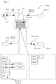
- Figure 1 represents a simplified ozone generating machine OGM comprising an ozone generator OG where a plurality of electrodes sets EKW are placed within a housing H, as shown in figure 3 .
- the ozone generating machine OGM comprises an Handler HDL, an identification code ID indicating a type of ozone generating machine, four data storing devices Mem1, Mem2, Mem3, Mem 4, being attached or not the ozone generating machine OGM and being or not grouped in a single common data storing device, an human-machine interface HMI to allow communication between an operator OP and the ozone generating machine OGM, a set of sensor MS arranged for emitting at least one sensor signal SSI, a set of actuators ACT arranged to be controlled by at least one actuator control signal ACS, a calculation unit CPU arranged for implementing a method for controlling the ozone generating machine OGM below illustrated, an inlet or input O2IN arranged to supply oxygen from an consumable source OCS, such as oxygen bottles or oxygen batch, and an outlet or output O3OUT arranged to exhaust ozone, an inlet of water cooling WCIN and an outlet of water cooling WCOUT.
- an identification code ID indicating a type of o
- Said ozone generating machine OGM further comprises an ozone concentration sensor O3S installed or mounted at the output of the ozone generating machine OGM, and arranged for measuring an actual ozone concentration O3CA.
- the ozone generating machine OGM further comprises at least an ozone pressure sensor OPS, an ozone circulation flow sensor O3Q, an inlet water cooling temperature sensor IWCTS and an outlet water cooling temperature sensor OWCTS, an inlet water cooling flow sensor IWCQS and an outlet water cooling flow sensor OWCQS, an electrode power sensor EPS, an electrode intensity sensor and an electrode voltage sensor, a consumable source sensor CCS, a circulation pump sensor CPS, such as pressure sensor and/or flow sensor.
- the ozone generating machine OGM further comprises at least an electric unit, an oxygen circulation pump OCP, and at least two electrodes EKW separated by an ozonizing gap OZ shown in figure 3 and a dielectric layer, wherein oxygen is supplied from the inlet O2IN of the ozone generating machine OGM by the oxygen circulation pump OCP to the ozonizing gap OZ where electrical power in form of electrical discharges allowing corona effect is transforming the oxygen into ozone, circulated to the outlet or output O3OUT of the ozone generating machine OGM.
- the ozone generating machine OGM further comprises a water cooling circuit arranged for cooling the electrodes EKW, comprising said water cooling inlet WCIN and said water cooling outlet WCOUT.
- the electrodes are metallic, and the dielectric layer comprises a ceramic coating, applied onto at least one of the electrodes.
- the ozone generating machine OGM further comprises a system configuration file Sysconf, comprising a set of sensor coefficients SK and a set of actuator coefficients AK.
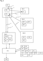
- Figure 2 represents a method for controlling an ozone generating machine according to the present invention.
- the operator OP is connecting to the ozone generating machine OGM the second data storing device Mem2 storing a set of base of setting files BSF, wherein each base setting file BSF is dedicated to a type of ozone generating machine OGM.
- This connection can be done either by connecting an USB storing device to a receiving docket of the machine OGM, by connecting the machine OGM to a Wi-Fi network in relation with the second data storing device Mem2, by connecting the machine OGM to a server with authentication key, or the like.
- the handler HDL part of the ozone generating machine OGM, is retrieving and reading 1 the identification code ID of the ozone generating machine OGM.
- the identification code has been put through 3 the human-machine interface HMI by 2 the operator OP in the first data storing device Mem1.
- the Handler HDL retrieves and reads in the second data storing device Mem2 a dedicated base setting file BSF corresponding to the type of ozone generating machine OGM indicated by the identification code ID.
- the Handler HDL encodes and writes 5 on the forth data storing device Mem4 the system configuration file Sysconf based on the dedicated base setting file BSF.
- the system configuration file Sysconf comprises the set of sensor coefficients SK and the set of actuator coefficients AK.
- the Handler HDL retrieves 6 on the third data storing device Mem3 storing a set of options setting files OSF an options setting file OSF corresponding to the type of ozone generating machine OGM indicated by the identification code ID.
- the Handler HDL overwrites 7 a part of the system configuration file Sysconf based on the options setting file OSF, adding or replacing part of the system configuration file Sysconf.
- the ozone generating machine OGM is producing ozone, with the step of correcting the at least one sensor signal SSI emitted by the at least one sensor MS with at least one sensor coefficients SK or actuating the at least one actuator ACT with the at least one actuator control signal ACS corrected by at least one actuator coefficients AK, thanks to the calculation unit CPU.
- the sensors MS are calibrated thanks to the sensor coefficients SK which correct the sensor signals SSI so that corrected signals or corrected values are available, in order to represent the real physical situation of the ozone generating machine OGM.
- the actuator coefficients AK are correcting the actuators signals ACS so that the actuators AC are well controlled.
- method further comprises a step of determining a predicted ozone concentration O3CP at the output of the ozone generating machine OGM, based on the sensor signals SSI and the actuator control signals ACS.
- the predicted ozone concentration O3CP is based on the pump flow value or measure given by the oxygen circulation pump OCP and measured by the circulation pump sensor CPS and on the power consumed by the two electrodes EKW separated by the ozonizing gap and the dielectric layer, and measured by the electrode power sensor EPS.
- Other sensor signals SSI and actuator control signals ACS may be used in order to refine the predicted ozone concentration O3CP.
- oxygen circulation pump OCP is a compressor and the ozone generating machine OGM further comprises a pressure regulator such as a relief valve or a pressure valve so that oxygen under pressure is supplied to the ozone generator OG where pressure is lower.
- the actual ozone concentration O3CA is measured thanks to the ozone concentration sensor O3S and compared to the predicted ozone concentration O3CP.
- a discrepancy DIS is revealed, that is to say a discrepancy DIS is higher than an ozone concentration threshold FT
- the set of sensor coefficients SK and the set of actuators coefficients AK is corrected and overwritten, based on the actual ozone concentration O3CA and/or the discrepancy DIS.
- the correction is preferred to be made with the actual ozone concentration O3CA and/or the discrepancy DIS
- the correction and overwriting can be made with any other relevant sensor signals SSI or actuator control signals ACS, or any other relevant information linked to the ozone generating machine OGM production.
- the set of sensor coefficients SK and set of actuator coefficients AK should be updated accordingly, to retrieve the expected or desired ozone concentration, as it is well known that ozone generating machine are producing ozone with the time drift.
- the set of actuator coefficients AK can be corrected by increasing the value of the coefficients corresponding respectively PFK, EPK to the flow of oxygen circulation pump OCP or to the power consumed by the electrodes EKW, so that a desired ozone concentration is reached again.
- the ozone concentration sensor O3S can be mounted directly at the output O3OUT of the ozone generating machine OGM or on a distribution circuit located downstream the output O3OUT of the ozone generating machine OGM, so that the ozone concentration sensor O3S can be either installed on a new machine, than on a revamped machine, already installed and running since a certain time, for which a better control of the ozone concentration is desired.
- the previous steps can be done on a regular basis according the ozone production, but also at higher frequency or more regularly.
- the ozone concentration threshold FT can be defined at 10%, more preferably at 5%.
- the ozone generating machine OGM is also equipped with the consumable source OCS such as oxygen tank or bottle or oxygen batch.
- the presence or status of the consumable source OCS is measured by the consumable source sensor CCS, emitting a status such as ready or empty.
- this change can be monitored by the consumable source sensor CCS or entered by the operator OP via the human-machine interface HMI, and the determination of the predicted ozone concentration O3CA, measuring actual concentration O3CA, comparing both, and correcting and overwriting the set of sensor coefficients SK or actuators coefficients AK and/or any other step can be done so that desired ozone concentration is reached or maintained.
- the consumable source sensor CCS can be a mechanical presence sensor arranged for detecting a removal of the oxygen tank or bottle, or can be a flow sensor if the oxygen tank contains several oxygen batches and a switching between the oxygen batches is operated and detected by the flow sensor.
- the power threshold ST can be defined at 10%, more preferably at 5%.
- Prompting a message to the operator OP can also be done to inform him about a ozone production drift, or any other information from the sensor signals or the predicted ozone concentration O3CP or actual ozone concentration O3CA.
- FIG. 3 shows that cooling water WC is present in the ozone generator OG.
- the ozone generator comprises an inlet of water cooling WCIN, and an outlet of water cooling WCOUT.
- the predicted ozone concentration O3CP can be determined as follow: the concentration is a function of feed gas pressure, power density, cooling water temperature, frequency of electric current applied to the ozone generator, specific flow as gas flow in kg/h per unit of active surface.
- the units for each parameters of the ozone generating machine OGM are indicated in parenthesis.
- Ozone concentration % by weight b 0 + b 1 * Pressure bara + b2 * Power Density kW/m 2 + b 3 * cooling water temperature C + b4 * frequency Hz + b5 * Specific Flow kg/h/m 2 + b6*Pressure bara * Pressure bara + b7 * Pressure bara * Power Density kW/m 2 + b8 * Pressure bara * cooling water temperature C + b9 * Pressure bara * frequency Hz + b10 * Pressure bara * Specific Flow kg/h/m 2 + b11 * Power Density kW/m 2 * Power Density kW/m 2 + b12 * Power Density kW/m 2 * cooling water Temperature C + b13 * Power Density kW/m 2 * frequency Hz + b14 * Power Density kW/m 2 * Specific Flow kg/h/m 2 + b15 * cooling water temperature C * cooling water temperature C + b16 * cooling water temperature C * frequency Hz + b
- the ozone generating machine OGM is set to produce 5kg/h of ozone at a certain concentration at the outlet of the machine.
- the request to change production to 7 kg/h comes from a plant control or from a user request: instead of sweeping power and flow to reach the new required production, the control unit will jump to value of power and gas flow supposed to deliver 7kg/h, based on the parameters and sensors and actuators coefficients SK, AK. If the predictions is not fully adequate, some further proportional-integral-derivative controller, well known as PID controller, will be engaged to reach the target. Still the change from 5 to 7 kg/h will be quicker and control of the ozone generating machine OGM will be improved.
- the predetermined coefficients are relevant especially to allow this quick or fast regulation.
- the auto-tune mode has the role to make this regulation more precise. Furthermore, the auto-tune mode could reveal drifts in the system (self-diagnostic, pre-warning for defects, deterioration or the like).
- the same can be done to jump to an other ozone concentration at the outlet of the machine, or to other parameter that the user would like to adjust.
- Such a model is typically determined by running a measurement campaign according to a design of experiments (DoE) measurement plan.
- DoE design of experiments
- a prototype for each new technology or a machine of existing technology is connected to process control and measurement instrumentation, preferably with high precision/accuracy.
- a measurement plan with variables according to the rules of design of experiments is generated where all variables are varied over the required range [Ref.: Myers, Raymond H. Response Surface Methodology. Boston: Allyn and Bacon, Inc., 1971 ]. This range could be, as an example:
Landscapes
- Chemical & Material Sciences (AREA)
- Organic Chemistry (AREA)
- Physics & Mathematics (AREA)
- General Physics & Mathematics (AREA)
- Engineering & Computer Science (AREA)
- Automation & Control Theory (AREA)
- Inorganic Chemistry (AREA)
- Oxygen, Ozone, And Oxides In General (AREA)
Description
- The present invention relates to the field of water treatment thanks to ozone, and relates in particular to a method for controlling an ozone generating machine.
- It is known from the prior art documents
WO97/49636 A1 US2006049738 a method for controlling an ozone generating machine, which presents a number a sensors, actuators and devices to be controlled so as to produce a required amount of ozone (concentration, flow, pressure...). Such machine is often dedicated to a specific range of production of ozone, or to specific requirements from a client and necessitates a specific control unit. In addition, it is known that sensors, actuators can deviate from their nominal functioning, thereby inducing deviations in the ozone production. - The disadvantages of the method proposed by this document are that it is required to design and manufacture a dedicated control unit for each specific range of production of ozone, or for each specific requirements of a client, and there is no possibility to have a flexible controlling method for an installed park of machines.
- An aim of the present invention is to deal with disadvantages of the prior art document mentioned above, and in particular to propose a method for controlling an ozone generating machine that is flexible and adaptable to different types of machine to improve maintainability and learnability of the whole installed park of machines, but also to reduce the ozone production variability despite variability or drift of sensors and actuators of the ozone generating machine.
- A first aspect of the present invention is a method for controlling an ozone generating machine comprising :
- a control unit,
- at least one sensor arranged for emitting at least one sensor signal to the control unit,
- at least one actuator arranged to be controlled by at least one actuator control signal generated by the control unit, and
- an ozone generating machine identification code,
- connecting to the ozone generating machine a data storing device storing a set of base setting files,
wherein each base setting file is dedicated to a type of ozone generating machine, and - reading the ozone generating machine identification code indicating the type of the ozone generating machine, and
- retrieving and reading on the data storing device a dedicated base setting file corresponding to the type of the ozone generating machine indicated by the identification code, and
- encoding and writing on an end user data storing device a system configuration file based on the dedicated base setting file, the system configuration file comprising at least a set of sensor coefficients and a set of actuator coefficients,
- producing ozone with the ozone generating machine, said ozone production step comprising at least a step of correcting the at least one sensor signal emitted by the at least one sensor with at least one sensor coefficient belonging to the set of sensor coefficients and/or actuating the at least one actuator with the at least one actuator control signal corrected by at least one actuator coefficient belonging to the set of actuator coefficients.
- This allows to propose a method for controlling an ozone generating machine with an high flexibility, with a common set of base setting files for the whole installed park of machines, but with a specific adaptation of the needs of a specific type of machine and also with an enhanced maintainability. Indeed, this allows a globalized correction of coefficients in all the installed park of machines but also to easier the installation and settings of coefficients on a specific machine. In particular, the same base setting files are available at the first run of the machine so that with the identification code, a specific configuration file is built to enable the adequate control of the machine with all its specific sensors and actuators. We hear by sensor signal a signal emitted by a sensor, representing the physical measure done by the sensor. We hear by actuator control signal a signal emitted by the control unit to control the actuator. Each type of ozone generating machine comprises an identification code. The system configuration file is used for controlling the ozone generating machine. In other words, the method allows to have several piloting coefficients files for sensor(s) and actuator(s), each file being dedicated to one of different machines.
- Advantageously, the method for controlling the ozone generating machine further comprises the steps of :
- determining a predicted ozone concentration at an output of the ozone generating machine based on the at least one sensor signal or on the at least one actuator control signal,
- measuring an actual ozone concentration with an ozone concentration sensor at the output of the ozone generating machine,
- comparing the predicted ozone concentration with the actual ozone concentration,
- correcting and overwriting the set of sensor coefficients and the set of actuator coefficients of the system configuration file based on the actual ozone concentration if a discrepancy between the predicted ozone concentration and the actual ozone concentration is more than an ozone concentration threshold.
- Advantageously, the method for controlling the ozone generating machine further comprises the steps of :
- step 1: determining a predicted ozone concentration at an output of the ozone generating machine based on the at least one sensor signal or on the at least one actuator control signal,
- step 2: measuring an actual ozone concentration with an ozone concentration sensor at the output of the ozone generating machine,
- step 3: comparing the predicted ozone concentration with the actual ozone concentration,
- step 4: correcting and overwriting the set of sensor coefficients and the set of actuator coefficients of the system configuration file based on the actual ozone concentration if a discrepancy between the predicted ozone concentration and the actual ozone concentration is more than an ozone concentration threshold.
- This allows to manage a drift of ozone concentration with the help of adjustments on sensors coefficients or actuators coefficients. This also allows to predict an ozone concentration so that both production and maintenance can be enhanced. Moreover, this allows to calibrate and to correct the sensor signals and the actuator control signals, thus improving the ozone production. Improvements can be then deployed on others machines due to the learnability of the ozone generating machine, thanks to the system configuration file. We hear by correcting the set of sensor coefficients and the set of actuator coefficient any correction that permits to reduce the discrepancy between the predicted ozone concentration and the actual ozone concentration either by correction the actuation or correcting the measurement. In other words, the method allows to control the machine, and not only to alert an operator with a failure message if a failure is detected.
- Advantageously, the method for controlling an ozone generating machine further comprises the step of:
- mounting the ozone concentration sensor on the ozone generating machine or on a distribution circuit located downstream an output connection of the ozone generating machine.
- This enables to better control the ozone concentration at the output of the ozone generating machine, and to allow an implementation of the method on the installed park of machine, for example on the distribution circuit. In particular, even if the machine is not equipped with an ozone concentration sensor, it is enough to install it on the machine, for the calibration step only. We hear by calibration step a measurement or checking of the signals emitted by sensors and emitted for controlling actuator and the corresponding correction of set of sensor coefficients and set of actuator coefficients. The mounting of the ozone concentration sensor is particularly interesting for a "plug and play" use, that is to say, using the ozone generating machine and checking on a regular basis, that there is no drift nor variation on the ozone production, and to recover expected ozone production if necessary.
- Advantageously, the method for controlling an ozone generating machine wherein the system configuration file contains a initial frequency to operate at least one of the steps of :
- determining a predicted ozone concentration at an output of the ozone generating machine based on the at least one sensor signal or on the at least one actuator control signal,
- measuring an actual ozone concentration with an ozone concentration sensor at the output of the ozone generating machine,
- comparing the predicted ozone concentration with the actual ozone concentration,
- correcting and overwriting the set of sensor coefficients and the set of actuator coefficients of the system configuration file based on the actual ozone concentration if a discrepancy between the predicted ozone concentration and the actual ozone concentration is more than an ozone concentration threshold,
- defining an updated frequency of the system configuration file to operate at least one of the steps of:
- determining a predicted ozone concentration at an output of the ozone generating machine based on the at least one sensor signal or on the at least one actuator control signal,
- measuring an actual ozone concentration with an ozone concentration sensor at the output of the ozone generating machine,
- comparing the predicted ozone concentration with the actual ozone concentration,
- correcting and overwriting the set of sensor coefficients and the set of actuator coefficients of the system configuration file based on the actual ozone concentration if a discrepancy between the predicted ozone concentration and the actual ozone concentration is more than an ozone concentration threshold,
based on the actual ozone concentration and/or the discrepancy, - correcting and overwriting said updated frequency of the system configuration file.
- Advantageously, the method for controlling an ozone generating machine further comprises the steps of:
- defining a frequency at which at least one of the steps of:
-
step 1 to 4 is implemented, - setting the frequency based on the actual ozone concentration and/or the discrepancy.
- This allows to better manage the ozone concentration and production, and to refine the precision of the prediction, the measurement, the comparison, the correction and the overwriting, so that values are checked whenever necessary. In other words, in normal conditions, low frequency is applied, to store/process minimum amount of data, but when necessary, the frequency is increased, to rapidly detect and react if a discrepancy or a drift is noticed.
- Advantageously, the method for controlling an ozone generating machine,
- the ozone generating machine further comprising at least one consumable source, such as at least one oxygen bottle or oxygen batch, and a consumable source sensor, arranged for indicating a status of the at least one consumable source, such as ready or empty,
- the method further comprises the steps of:
- monitoring the status of the at least one consumable source,
- executing at least one of the steps of:
- determining a predicted ozone concentration at an output of the ozone generating machine based on the at least one sensor signal or on the at least one actuator control signal,
- measuring an actual ozone concentration with an ozone concentration sensor at the output of the ozone generating machine,
- comparing the predicted ozone concentration with the actual ozone concentration,
- correcting and overwriting the set of sensor coefficients and the set of actuator coefficients of the system configuration file based on the actual ozone concentration if a discrepancy between the predicted ozone concentration and the actual ozone concentration is more than an ozone concentration threshold,
- if a change in the status is detected.
- Advantageously, the method for controlling an ozone generating machine,
- the ozone generating machine further comprising at least one consumable source, such as at least one oxygen bottle or oxygen batch, and a consumable source sensor, arranged for indicating a status of the at least one consumable source, such as ready or empty,
- the method further comprises the steps of:
- monitoring the status of the at least one consumable source,
- executing at least one of the steps of:
-
step 1 to 4,
- if a change in the status is detected.
- Advantageously, the method for controlling an ozone generating machine,
- the ozone generating machine further comprises at least one input arranged to supply oxygen from a consumable source, such as at least one oxygen tank,
- the method further comprising the steps of:
- executing at least one of the steps:
- determining a predicted ozone concentration at an output of the ozone generating machine based on the at least one sensor signal or on the at least one actuator control signal,
- measuring an actual ozone concentration with an ozone concentration sensor at the output of the ozone generating machine,
- comparing the predicted ozone concentration with the actual ozone concentration,
- correcting and overwriting the set of sensor coefficients and the set of actuator coefficients of the system configuration file based on the actual ozone concentration if a discrepancy between the predicted ozone concentration and the actual ozone concentration is more than an ozone concentration threshold,
- when the consumable source is changed.
- This allows a change of consumable and a fast calibration, correction and overwriting of the sensors coefficients and actuators coefficients, so that optimum control and efficiency of the ozone generating machine is reached.
- Advantageously, the ozone generating machine further comprises at least two electrodes separated by an ozonizing gap and a dielectric layer, and at least one electrode power sensor arranged for measuring a power consumed by the at least one electrode,
- the method further comprising:
- supplying electric power to the a least two electrodes so as to create electric discharges in the ozonizing gap,
- monitoring the power consumed by the at least two electrodes,
- executing at least one of the steps of:
- determining a predicted ozone concentration at an output of the ozone generating machine based on the at least one sensor signal or on the at least one actuator control signal,
- measuring an actual ozone concentration with an ozone concentration sensor at the output of the ozone generating machine,
- comparing the predicted ozone concentration with the actual ozone concentration,
- correcting and overwriting the set of sensor coefficients and the set of actuator coefficients of the system configuration file based on the actual ozone concentration if a discrepancy between the predicted ozone concentration and the actual ozone concentration is more than an ozone concentration threshold,
- when a power change higher than a power threshold is detected.
- Advantageously, the ozone generating machine further comprises at least two electrodes separated by an ozonizing gap and a dielectric layer, and at least one electrode power sensor arranged for measuring a power consumed by the at least one electrode,
- the method further comprising:
- supplying electric power to the a least two electrodes so as to create electric discharges in the ozonizing gap,
- monitoring the power consumed by the at least two electrodes,
- executing at least one of the steps of:
-
step 1 to 4,
- when a power change higher than a power threshold is detected.
- This allows to detect an electrode power drift of the electrode actuator so that fixing of the ozone generating machine can be done and ozone generation can be kept efficient and appropriate. A prompt message can be issued to alert on the power change or power drift.
- Advantageously, the ozone generating machine further comprising at least two electrodes, wherein the set of actuator coefficients comprises at least one electrode power coefficient,
the method further comprising the step of: - correcting and overwriting the at least one electrode power coefficient of the system configuration file based on the actual ozone concentration and/or the discrepancy.
- This enables to propose a highly efficient and flexible ozone generating machine, so that ozone concentration is maintained as desired, by adapting electrode power.
- Advantageously, the ozone generating machine further comprises at least one pump, such as a oxygen circulation pump,
wherein the set of actuator coefficients comprises a pump flow coefficient, the method further comprising the step of: - correcting and overwriting the pump flow coefficient of the system configuration file based on the actual ozone concentration and/or the discrepancy.
- Advantageously, the ozone generating machine is supplied with oxygen under pressure, and further comprises a pressure regulator to regulate oxygen pressure flowing from oxygen supply to ozone generator where pressure is lower.
- This allows to propose an efficient and adaptive ozone generating machine, so that ozone production is improved, by adapting pump flow of the pump actuator or compressor, or by adapting gas pressure.
- A second aspect of the present invention concerns an ozone generating machine, comprising:
- at least two electrodes,
- an electric power unit connected to the at least two electrodes,
- at least one sensor,
- at least one actuator,
- at least one data storing device, comprising an end user data storing device wherein a system configuration file comprising at least a set of sensor coefficients and a set of actuator coefficients is written, and
- a control unit arranged to control the at least one actuator, the electric power unit, the at least two electrodes, and to correct and overwrite the set of sensor coefficients and the set of actuator coefficients of the system configuration file, so as to implement the method according to the first aspect of the present invention.
- In summary, the control unit is arranged to retrieve and read in the at least one data storing device the identification code, the basic setting file, the options setting file, to encode and write on the end user data storing device the system configuration file, to generate the at least one actuator control signal to control the at least one actuator, to receive the at least one sensor signal emitted by the at least one sensor signal, to determine the predicted ozone concentration, to compare it with the actual ozone concentration, to correct and overwrite the set of sensor coefficients and set of actuator coefficients of the system configuration file, to define the updated frequency to operate the said method, to correct and overwrite said updated frequency, to monitor consumable change, to monitor power consumed by electrode, and in a general manner to monitor sensors, and in general manner also to implement any step of the method for controlling the ozone generating machine.
- This allows to propose an ozone generating machine with optimum control and efficiency, high flexibility and improved maintainability, arranged to implement a method according to the first aspect of the present invention.
- Other features and advantages of the present invention will appear more clearly from the following detailed description of particular non-limitative examples of the invention, illustrated by the appended drawings where:
-
figure 1 represents an ozone generating machine according to the present invention ; -
figure 2 represents a method for controlling an ozone generating machine according to the present invention; -
figure 3 represents a cross section of an ozone generator of the ozone generating machine offigure 1 . -
Figure 1 represents a simplified ozone generating machine OGM comprising an ozone generator OG where a plurality of electrodes sets EKW are placed within a housing H, as shown infigure 3 . - The ozone generating machine OGM comprises an Handler HDL, an identification code ID indicating a type of ozone generating machine, four data storing devices Mem1, Mem2, Mem3,
Mem 4, being attached or not the ozone generating machine OGM and being or not grouped in a single common data storing device, an human-machine interface HMI to allow communication between an operator OP and the ozone generating machine OGM, a set of sensor MS arranged for emitting at least one sensor signal SSI, a set of actuators ACT arranged to be controlled by at least one actuator control signal ACS, a calculation unit CPU arranged for implementing a method for controlling the ozone generating machine OGM below illustrated, an inlet or input O2IN arranged to supply oxygen from an consumable source OCS, such as oxygen bottles or oxygen batch, and an outlet or output O3OUT arranged to exhaust ozone, an inlet of water cooling WCIN and an outlet of water cooling WCOUT. - Said ozone generating machine OGM further comprises an ozone concentration sensor O3S installed or mounted at the output of the ozone generating machine OGM, and arranged for measuring an actual ozone concentration O3CA. The ozone generating machine OGM further comprises at least an ozone pressure sensor OPS, an ozone circulation flow sensor O3Q, an inlet water cooling temperature sensor IWCTS and an outlet water cooling temperature sensor OWCTS, an inlet water cooling flow sensor IWCQS and an outlet water cooling flow sensor OWCQS, an electrode power sensor EPS, an electrode intensity sensor and an electrode voltage sensor, a consumable source sensor CCS, a circulation pump sensor CPS, such as pressure sensor and/or flow sensor.
- The ozone generating machine OGM further comprises at least an electric unit, an oxygen circulation pump OCP, and at least two electrodes EKW separated by an ozonizing gap OZ shown in
figure 3 and a dielectric layer, wherein oxygen is supplied from the inlet O2IN of the ozone generating machine OGM by the oxygen circulation pump OCP to the ozonizing gap OZ where electrical power in form of electrical discharges allowing corona effect is transforming the oxygen into ozone, circulated to the outlet or output O3OUT of the ozone generating machine OGM. The ozone generating machine OGM further comprises a water cooling circuit arranged for cooling the electrodes EKW, comprising said water cooling inlet WCIN and said water cooling outlet WCOUT. - In an embodiment, the electrodes are metallic, and the dielectric layer comprises a ceramic coating, applied onto at least one of the electrodes.
- The ozone generating machine OGM further comprises a system configuration file Sysconf, comprising a set of sensor coefficients SK and a set of actuator coefficients AK.
-
Figure 2 represents a method for controlling an ozone generating machine according to the present invention. - The operator OP is connecting to the ozone generating machine OGM the second data storing device Mem2 storing a set of base of setting files BSF, wherein each base setting file BSF is dedicated to a type of ozone generating machine OGM. This connection can be done either by connecting an USB storing device to a receiving docket of the machine OGM, by connecting the machine OGM to a Wi-Fi network in relation with the second data storing device Mem2, by connecting the machine OGM to a server with authentication key, or the like.
- The handler HDL, part of the ozone generating machine OGM, is retrieving and reading 1 the identification code ID of the ozone generating machine OGM. In the example given only for illustration, the identification code has been put through 3 the human-machine interface HMI by 2 the operator OP in the first data storing device Mem1.
- Then, the Handler HDL retrieves and reads in the second data storing device Mem2 a dedicated base setting file BSF corresponding to the type of ozone generating machine OGM indicated by the identification code ID.
- Then, the Handler HDL encodes and writes 5 on the forth data storing device Mem4 the system configuration file Sysconf based on the dedicated base setting file BSF. The system configuration file Sysconf comprises the set of sensor coefficients SK and the set of actuator coefficients AK.
- Then, the Handler HDL retrieves 6 on the third data storing device Mem3 storing a set of options setting files OSF an options setting file OSF corresponding to the type of ozone generating machine OGM indicated by the identification code ID.
- Then, the Handler HDL overwrites 7 a part of the system configuration file Sysconf based on the options setting file OSF, adding or replacing part of the system configuration file Sysconf.
- Then, the ozone generating machine OGM is producing ozone, with the step of correcting the at least one sensor signal SSI emitted by the at least one sensor MS with at least one sensor coefficients SK or actuating the at least one actuator ACT with the at least one actuator control signal ACS corrected by at least one actuator coefficients AK, thanks to the calculation unit CPU.
- In other words, the sensors MS are calibrated thanks to the sensor coefficients SK which correct the sensor signals SSI so that corrected signals or corrected values are available, in order to represent the real physical situation of the ozone generating machine OGM. In a similar manner, the actuator coefficients AK are correcting the actuators signals ACS so that the actuators AC are well controlled.
- Then, method further comprises a step of determining a predicted ozone concentration O3CP at the output of the ozone generating machine OGM, based on the sensor signals SSI and the actuator control signals ACS. In other words, the predicted ozone concentration O3CP is based on the pump flow value or measure given by the oxygen circulation pump OCP and measured by the circulation pump sensor CPS and on the power consumed by the two electrodes EKW separated by the ozonizing gap and the dielectric layer, and measured by the electrode power sensor EPS. Other sensor signals SSI and actuator control signals ACS may be used in order to refine the predicted ozone concentration O3CP. In an advantageous example, oxygen circulation pump OCP is a compressor and the ozone generating machine OGM further comprises a pressure regulator such as a relief valve or a pressure valve so that oxygen under pressure is supplied to the ozone generator OG where pressure is lower.
- Then, the actual ozone concentration O3CA is measured thanks to the ozone concentration sensor O3S and compared to the predicted ozone concentration O3CP.
- If a discrepancy DIS is revealed, that is to say a discrepancy DIS is higher than an ozone concentration threshold FT, the set of sensor coefficients SK and the set of actuators coefficients AK is corrected and overwritten, based on the actual ozone concentration O3CA and/or the discrepancy DIS. Although the correction is preferred to be made with the actual ozone concentration O3CA and/or the discrepancy DIS, the correction and overwriting can be made with any other relevant sensor signals SSI or actuator control signals ACS, or any other relevant information linked to the ozone generating machine OGM production.
- In other words, if the prediction of ozone concentration is false or showing a time drift, the set of sensor coefficients SK and set of actuator coefficients AK should be updated accordingly, to retrieve the expected or desired ozone concentration, as it is well known that ozone generating machine are producing ozone with the time drift.
- For example, the set of actuator coefficients AK can be corrected by increasing the value of the coefficients corresponding respectively PFK, EPK to the flow of oxygen circulation pump OCP or to the power consumed by the electrodes EKW, so that a desired ozone concentration is reached again.
- The ozone concentration sensor O3S can be mounted directly at the output O3OUT of the ozone generating machine OGM or on a distribution circuit located downstream the output O3OUT of the ozone generating machine OGM, so that the ozone concentration sensor O3S can be either installed on a new machine, than on a revamped machine, already installed and running since a certain time, for which a better control of the ozone concentration is desired.
- The previous steps can be done on a regular basis according the ozone production, but also at higher frequency or more regularly. In other words, when a drift is detected on the ozone production or on the ozone concentration, the step of determining the predicted ozone concentration O3CP, measuring the actual ozone concentration O3CA and comparing the predicted ozone concentration O3CP to the actual ozone concentration O3CA, and correcting and overwriting the set of correcting and overwriting the set of sensor coefficients SK and the set of actuator coefficients AK of the system configuration file Sysconf based on the actual ozone concentration O3CA if a discrepancy DIS between the predicted ozone concentration O3CP and the actual ozone concentration O3CA is more than an ozone concentration threshold FT, can be done more frequently or oftently, so that the drift of ozone production or ozone concentration is kept into control or avoided. The ozone concentration threshold FT can be defined at 10%, more preferably at 5%. To this aim, the ozone generating machine OGM further comprises an oscilloscope to measure the frequencies.
- The ozone generating machine OGM is also equipped with the consumable source OCS such as oxygen tank or bottle or oxygen batch. The presence or status of the consumable source OCS is measured by the consumable source sensor CCS, emitting a status such as ready or empty. In other words, if the consumable source OCS is changed, this change can be monitored by the consumable source sensor CCS or entered by the operator OP via the human-machine interface HMI, and the determination of the predicted ozone concentration O3CA, measuring actual concentration O3CA, comparing both, and correcting and overwriting the set of sensor coefficients SK or actuators coefficients AK and/or any other step can be done so that desired ozone concentration is reached or maintained. That is to say the consumable source sensor CCS can be a mechanical presence sensor arranged for detecting a removal of the oxygen tank or bottle, or can be a flow sensor if the oxygen tank contains several oxygen batches and a switching between the oxygen batches is operated and detected by the flow sensor.
- Other step can also be done, such as monitoring the power consumed by the electrodes EKW and executing the steps of determining the predicted ozone concentration O3CA and other relevant steps, if a power change higher than a power threshold ST is detected. The power threshold ST can be defined at 10%, more preferably at 5%.
- Prompting a message to the operator OP can also be done to inform him about a ozone production drift, or any other information from the sensor signals or the predicted ozone concentration O3CP or actual ozone concentration O3CA.
- In addition, it is therefore possible to deploy and update the set of sensor coefficients SK and the set of actuator coefficients AK from an advanced ozone generating machine OGM, for example having more options in the options setting files OSF and options installed on the ozone generating machine OGM directly, so that awareness of the machine or production is enhanced, to other ozone generating machines OGM from the installed park of machines, so that experience feedback or return REX can be implemented.
-
Figure 3 shows that cooling water WC is present in the ozone generator OG. The ozone generator comprises an inlet of water cooling WCIN, and an outlet of water cooling WCOUT. - It is possible to produce ozone with a high efficiency and high management of the ozone generating machine OGM by determining the predicted ozone concentration O3CP, thereby trying to reach this value by the management of the set of sensor coefficients SK and set of actuator coefficients AK, and comparing the reached value of ozone, that is the measured ozone concentration or actual ozone concentration O3CA, and overwriting the set of coefficients SK, AK as necessary according to the discrepancy DIS detected between the predicted ozone concentration O3CP and the actual ozone concentration O3CA, to better adjust the running of the ozone generating machine OGM.
- As an example, the predicted ozone concentration O3CP can be determined as follow:
the concentration is a function of feed gas pressure, power density, cooling water temperature, frequency of electric current applied to the ozone generator, specific flow as gas flow in kg/h per unit of active surface. The units for each parameters of the ozone generating machine OGM are indicated in parenthesis.

- The coefficient b0 to b20 are given bellow, with a value of uncertainty +/-.


- In other words, it is possible to have an auto-tune mode to control the ozone generating machine OGM, wherein the values of sensors are checked after a certain time of production and the set of coefficients SK, AK are overwritten to refine the control of the ozone generating machine OGM. It is also possible to have a quick regulation mode, to go faster to a given running point of the ozone generating machine OGM while was in an other running point.
- As a running example, the ozone generating machine OGM is set to produce 5kg/h of ozone at a certain concentration at the outlet of the machine. The request to change production to 7 kg/h comes from a plant control or from a user request: instead of sweeping power and flow to reach the new required production, the control unit will jump to value of power and gas flow supposed to deliver 7kg/h, based on the parameters and sensors and actuators coefficients SK, AK. If the predictions is not fully adequate, some further proportional-integral-derivative controller, well known as PID controller, will be engaged to reach the target. Still the change from 5 to 7 kg/h will be quicker and control of the ozone generating machine OGM will be improved. The predetermined coefficients are relevant especially to allow this quick or fast regulation. The auto-tune mode has the role to make this regulation more precise. Furthermore, the auto-tune mode could reveal drifts in the system (self-diagnostic, pre-warning for defects, deterioration or the like).
- The same can be done to jump to an other ozone concentration at the outlet of the machine, or to other parameter that the user would like to adjust.
- Such a model is typically determined by running a measurement campaign according to a design of experiments (DoE) measurement plan. To determine the coefficients of the model describing the physical behaviour of the technology with changing variables, a prototype for each new technology or a machine of existing technology is connected to process control and measurement instrumentation, preferably with high precision/accuracy. Subsequently, a measurement plan with variables according to the rules of design of experiments is generated where all variables are varied over the required range [Ref.: Myers, Raymond H. Response Surface Methodology. Boston: Allyn and Bacon, Inc., 1971]. This range could be, as an example:
- ozone concentration between [1;5] %-wt
- pressure between [1;2] bar-a
- power density between [0.5;2.5] kW/m2
- cooling water temperature between [5;40] °C
- frequency between [500;1000] Hz.
- Subsequently, a mathematical function suitable to model the physical behaviour of the system in the required range of values for each variable, in our case a fully quadratic polynomial of the form is chosen. After measuring a sufficient number of variable combinations, a linear regression analysis of the recorded dataset is performed in order to determine the exact values of all coefficients bi (i = 0...20).
- It should be noted that other mathematical functions, included but not limited to polynomials of different order, logarithmic or exponential functions, power functions, or combinations thereof could be used. It is of course understood that obvious improvements and/or modifications for one skilled in the art may be implemented, still being under the scope of the invention as it is defined by the appended claims.
Claims (9)
- Method for controlling an ozone generating machine (OGM) comprising:- a control unit,- at least one sensor (MS) arranged for emitting at least one sensor signal (SSI) to the control unit,- at least one actuator (ACT) arranged to be controlled by at least one actuator control signal (ACS) generated by the control unit and- an ozone generating machine identification code (ID),the method comprising the steps of:- connecting to the ozone generating machine (OGM) a data storing device (Mem2) storing a set of base setting files (BSF),
wherein each base setting file (BSF) is dedicated to a type of ozone generating machine (OGM), and- reading the ozone generating machine identification code (ID) indicating the type of the ozone generating machine (OGM), and- retrieving and reading on the data storing device (Mem2) a dedicated base setting file (BSF) corresponding to the type of the ozone generating machine (OGM) indicated by the identification code (ID), and- encoding and writing on an end user data storing device (Mem4) a system configuration file (Sysconf) based on the dedicated base setting file (BSF), the system configuration file (Sysconf) comprising at least a set of sensor coefficients (SK) and a set of actuator coefficients (AK),- producing ozone with the ozone generating machine (OGM), said ozone production step comprising at least a step of correcting the at least one sensor signal (SSI) emitted by the at least one sensor (MS) with at least one sensor coefficient (SK) belonging to the set of sensor coefficients (SK) and/or actuating the at least one actuator (ACT) with the at least one actuator control signal (ACS) corrected by at least one actuator coefficient (AK) belonging to the set of actuator coefficients (AK). - Method for controlling an ozone generating machine (OGM) according to the preceding claim, further comprising the steps of :- determining a predicted ozone concentration (O3CP) at an output of the ozone generating machine (OGM) based on the at least one sensor signal (SSI) or on the at least one actuator control signal (ACS),- measuring an actual ozone concentration (O3CA) with an ozone concentration sensor (O3S) at the output of the ozone generating machine (OGM),- comparing the predicted ozone concentration (O3CP) with the actual ozone concentration (O3CA),- correcting and overwriting the set of sensor coefficients (SK) and the set of actuator coefficients (AK) of the system configuration file (Sysconf) based on the actual ozone concentration (O3CA) if a discrepancy (DIS) between the predicted ozone concentration (O3CP) and the actual ozone concentration (O3CA) is more than an ozone concentration threshold (FT).
- Method for controlling an ozone generating machine (OGM) according to the preceding claim, further comprising the step of:- mounting the ozone concentration sensor (O3S) on the ozone generating machine (OGM) or on a distribution circuit located downstream an output connection of the ozone generating machine (OGM).
- Method for controlling an ozone generating machine (OGM) according to claim 2 or 3, wherein the system configuration file (Sysconf) contains an initial frequency to operate at least one of the steps of claim 2, the method further comprising the steps of:- defining an updated frequency of the system configuration file (Sysconf) to operate at least one of the steps of claim 2 based on the actual ozone concentration (O3CA) and/or the discrepancy (DIS),- correcting and overwriting said updated frequency of the system configuration file (Sysconf).
- Method for controlling an ozone generating machine (OGM) according to any one of claims 2 to 4,
the ozone generating machine (OGM) further comprising at least one input (O2IN) arranged to supply oxygen from a consumable source (OCS), such as at least one oxygen tank, the method further comprising the steps of:- executing at least one of the steps of claim 2 when the consumable source (OCS) is changed. - Method for controlling an ozone generating machine (OGM) according to any one of claims 2 to 5,the ozone generating machine (OGM) further comprising at least two electrodes (EKW) separated by an ozonizing gap (OZ) (OZ) and a dielectric layer, and at least one electrode power sensor (EPS) arranged for measuring a power consumed by the at least one electrode (EKW),the method further comprising:- supplying electric power to the a least two electrodes (EKW) so as to create electric discharges in the ozonizing gap (OZ) (OZ),- monitoring the power consumed by the at least two electrodes (EKW),- executing at least one of the steps of claim 2 when a power change higher than a power threshold (ST) is detected.
- Method for controlling an ozone generating machine (OGM) according to any one of claims 2 to 5,the ozone generating machine (OGM) further comprising at least two electrodes (EKW), wherein the set of actuator coefficients (AK) comprises at least one electrode power coefficient (EPK),the method further comprising the step of:- correcting and overwriting the at least one electrode power coefficient (EPK) of the system configuration file (Sysconf) based on the actual ozone concentration (O3CA) and/or the discrepancy (DIS).
- Method for controlling an ozone generating machine (OGM) according to any one of claims 2 to 7,the ozone generating machine (OGM) further comprising at least one oxygen pump, such as an oxygen circulation pump,wherein the set of actuator coefficients (AK) comprises a pump flow coefficient (PFK),the method further comprising the step of:- correcting and overwriting the pump flow coefficient (PFK) of the system configuration file (Sysconf) based on the actual ozone concentration (O3CA) and/or the discrepancy (DIS).
- An ozone generating machine (OGM), comprising:- at least two electrodes (EKW),- an electric power unit connected to the at least two electrodes,- at least one sensor (MS),- at least one actuator (ACT),- at least one data storing device (Mem1, Mem2, Mem3, Mem4), comprising an end user data storing device (Mem4) wherein a system configuration file (Sysconf) comprising at least a set of sensor coefficients (SK) and a set of actuator coefficients (AK) is written, and- a control unit arranged to control the at least one actuator (ACT), the electric power unit, the at least two electrodes, and to correct and overwrite the set of sensor coefficients (SK) and the set of actuator coefficients (AK) of the system configuration file (Sysconf), so as to implement the method according to any one of the preceding claims.
Applications Claiming Priority (2)
| Application Number | Priority Date | Filing Date | Title |
|---|---|---|---|
| EP17305838.9A EP3422124A1 (en) | 2017-06-30 | 2017-06-30 | Method for controlling an ozone generating machine |
| PCT/EP2018/067519 WO2019002529A1 (en) | 2017-06-30 | 2018-06-29 | Method for controlling an ozone generating machine |
Publications (2)
| Publication Number | Publication Date |
|---|---|
| EP3646124A1 EP3646124A1 (en) | 2020-05-06 |
| EP3646124B1 true EP3646124B1 (en) | 2022-01-26 |
Family
ID=59350826
Family Applications (2)
| Application Number | Title | Priority Date | Filing Date |
|---|---|---|---|
| EP17305838.9A Withdrawn EP3422124A1 (en) | 2017-06-30 | 2017-06-30 | Method for controlling an ozone generating machine |
| EP18737846.8A Active EP3646124B1 (en) | 2017-06-30 | 2018-06-29 | Method for controlling an ozone generating machine |
Family Applications Before (1)
| Application Number | Title | Priority Date | Filing Date |
|---|---|---|---|
| EP17305838.9A Withdrawn EP3422124A1 (en) | 2017-06-30 | 2017-06-30 | Method for controlling an ozone generating machine |
Country Status (5)
| Country | Link |
|---|---|
| US (1) | US11366440B2 (en) |
| EP (2) | EP3422124A1 (en) |
| CN (1) | CN110892343B (en) |
| ES (1) | ES2908137T3 (en) |
| WO (1) | WO2019002529A1 (en) |
Families Citing this family (3)
| Publication number | Priority date | Publication date | Assignee | Title |
|---|---|---|---|---|
| US20220390131A1 (en) * | 2021-06-04 | 2022-12-08 | Clear Path Holdings Corp. | Techniques for disinfection and deodorization of interior of buildings using ozone |
| CN117346075B (en) * | 2023-11-08 | 2026-04-10 | 拓荆创益(沈阳)半导体设备有限公司 | Ozone transmission system and control method and control device thereof |
| CN117236528B (en) * | 2023-11-15 | 2024-01-23 | 成都信息工程大学 | Ozone concentration forecasting method and system based on combined model and factor screening |
Family Cites Families (32)
| Publication number | Priority date | Publication date | Assignee | Title |
|---|---|---|---|---|
| WO1997049636A1 (en) * | 1995-05-26 | 1997-12-31 | Vasogen Inc. | Apparatus and method for calibrating and verifying the generation and delivery of ozone |
| US5540898A (en) * | 1995-05-26 | 1996-07-30 | Vasogen Inc. | Ozone generator with in-line ozone sensor |
| GB0109283D0 (en) * | 2001-04-12 | 2001-05-30 | Advanced Risc Mach Ltd | Testing for compliance |
| JP2003001087A (en) * | 2001-06-21 | 2003-01-07 | Toyota Auto Body Co Ltd | Method for controlling ozone concentration for ozone water forming apparatus |
| WO2004095716A2 (en) * | 2003-04-17 | 2004-11-04 | Fieldbus Foundation | System and method for implementing safety instrumented systems in a fieldbus architecture |
| TW200528390A (en) | 2004-02-25 | 2005-09-01 | Toshiba Mitsubishi Elec Inc | Apparatus and method of producing ozone gas |
| WO2006122276A1 (en) * | 2005-05-11 | 2006-11-16 | University Of North Texas | Instrument, system and method for automated low cost atmospheric measurements |
| CN101243369B (en) * | 2005-07-07 | 2010-12-15 | Mks仪器股份有限公司 | Ozone systems for multi-chamber tools |
| JP4856998B2 (en) * | 2006-03-22 | 2012-01-18 | 株式会社リコー | Image forming apparatus and image forming method |
| JP4353249B2 (en) * | 2007-01-19 | 2009-10-28 | トヨタ自動車株式会社 | Hydraulic actuator controller |
| WO2008104056A1 (en) * | 2007-02-26 | 2008-09-04 | Groupe Gecko Alliance Inc. | A method, device and system for use in configuring a bathing unit controller |
| EP2240270A1 (en) * | 2007-11-27 | 2010-10-20 | Purfresh, Inc. | Distributed networked ozonation system |
| AU2009214455A1 (en) * | 2008-02-15 | 2009-08-20 | Georgia Tech Research Corporation | Systems and methods for providing environment monitoring |
| JP2011075545A (en) * | 2009-09-01 | 2011-04-14 | Horiba Ltd | Gas sensor |
| JP2013544221A (en) * | 2010-11-22 | 2013-12-12 | エコヴィエ・カナダ・テクノロジーズ・インコーポレーテッド | Ozone generation system with precision adjustment |
| EP2690062B1 (en) * | 2011-03-24 | 2017-08-09 | Toshiba Mitsubishi-Electric Industrial Systems Corporation | Ozone gas supply system |
| US20130249808A1 (en) * | 2012-03-21 | 2013-09-26 | S. David Silk | System for implementing an overlay for a touch sensor including actuators |
| US9302912B2 (en) * | 2012-03-28 | 2016-04-05 | Mks Instruments, Inc. | Compact, configurable power supply for energizing ozone-producing cells |
| JP2013230797A (en) * | 2012-05-01 | 2013-11-14 | Nhk Spring Co Ltd | Display apparatus |
| CN102855150B (en) * | 2012-08-14 | 2016-02-10 | 北京华环电子股份有限公司 | A kind of method and system to equipment burning information to be programmed |
| US20160263261A1 (en) * | 2012-11-16 | 2016-09-15 | Samuel Richard Trapani | Method for intracorporeal disinfection using ultraviolet light and or ozone gas |
| CN104781527B (en) * | 2012-12-04 | 2017-11-14 | 日本特殊陶业株式会社 | Sensor control, sensory-control system and sensor control method |
| US10786588B2 (en) * | 2013-01-10 | 2020-09-29 | Gene Therapy Systems, Inc. | System and methods for sterilizing enclosed spaces using ozone |
| KR20160040509A (en) * | 2013-06-11 | 2016-04-14 | 유니버시티 오브 휴스턴 | Fixed and portable coating apparatuses and methods |
| CN104543620A (en) * | 2013-10-28 | 2015-04-29 | 合肥丰瑞隆生物科技有限公司 | Ozone control system for water purification and disinfection in faucets and pools |
| JP6734621B2 (en) * | 2014-02-20 | 2020-08-05 | オルガノ株式会社 | Ozone water supply method and ozone water supply device |
| CN103840731A (en) * | 2014-03-20 | 2014-06-04 | 天津市松正电动汽车技术股份有限公司 | Universal motor controller based on parameter self-learning |
| US9792748B2 (en) * | 2015-10-06 | 2017-10-17 | Alfonso Campalans | Neutral atmosphere and sanitization storage apparatus, method and system |
| CN105912330B (en) * | 2016-04-07 | 2019-11-29 | 北京北方华创微电子装备有限公司 | Hardware equipment control method and device |
| CN106020139B (en) * | 2016-05-13 | 2018-10-19 | 国网辽宁省电力有限公司电力科学研究院 | A kind of substation configuration description file consistency ensuring method based on flow management and control |
| US10471165B2 (en) * | 2016-08-26 | 2019-11-12 | Chemtreat, Inc. | Sterilization or disinfection of workpieces, including medical and dental instruments |
| US20180193507A1 (en) * | 2017-01-11 | 2018-07-12 | ClearWater Tech, LLC | Apparatus for Ozone Gas Disinfection of Closed Conduits |
-
2017
- 2017-06-30 EP EP17305838.9A patent/EP3422124A1/en not_active Withdrawn
-
2018
- 2018-06-29 ES ES18737846T patent/ES2908137T3/en active Active
- 2018-06-29 US US16/622,909 patent/US11366440B2/en active Active
- 2018-06-29 CN CN201880042011.2A patent/CN110892343B/en active Active
- 2018-06-29 WO PCT/EP2018/067519 patent/WO2019002529A1/en not_active Ceased
- 2018-06-29 EP EP18737846.8A patent/EP3646124B1/en active Active
Also Published As
| Publication number | Publication date |
|---|---|
| CN110892343A (en) | 2020-03-17 |
| US20200117157A1 (en) | 2020-04-16 |
| ES2908137T3 (en) | 2022-04-27 |
| WO2019002529A1 (en) | 2019-01-03 |
| EP3422124A1 (en) | 2019-01-02 |
| EP3646124A1 (en) | 2020-05-06 |
| CN110892343B (en) | 2023-07-25 |
| US11366440B2 (en) | 2022-06-21 |
Similar Documents
| Publication | Publication Date | Title |
|---|---|---|
| US11366440B2 (en) | Method for controlling an ozone generating machine | |
| KR102062593B1 (en) | Methods for monitoring a flow controller coupled to a process chamber | |
| EP3336425B1 (en) | Water quality management device, water treatment system, water quality management method, and water treatment system optimization program | |
| JP6268091B2 (en) | Method for in-situ calibration of flow controller | |
| EP3874332B1 (en) | Apparatus and methods for non-invasive closed loop step testing with controllable optimization relaxation | |
| CN104345232A (en) | Method and apparatus for predicting lifetime of a solenoid coil | |
| KR102573770B1 (en) | How to Control an Ozone Generator | |
| TW201126289A (en) | Method and apparatus for monitoring a process and/or a technical installation | |
| EP4198655A1 (en) | Establishing or improving a simulation model of an electrolyzer plant | |
| EP3338188B1 (en) | Method for determining a mean time to failure of an electrical device | |
| CN120879018B (en) | Emergency treatment system based on internal short circuit of solid-state battery | |
| JP5672276B2 (en) | Boiler system | |
| CN107407917B (en) | A method of controlling process equipment using transitional data | |
| KR20060125839A (en) | Method and control device for operation of internal combustion engine with injection system | |
| JP3047947B2 (en) | Plant monitoring equipment | |
| US20250164126A1 (en) | Electrode steam humidifier and method for its operation | |
| CN117148710A (en) | An adaptive plasma monitoring method and system | |
| KR20200113751A (en) | Apparatus for fault diagnosis of heater using power consumption and method thereof | |
| US20210181004A1 (en) | Method for determining individual fuel consumption characteristics of different generator units of a generating assembly | |
| CN118915837B (en) | A method and system for controlling voltage stabilization of oral irrigator | |
| RU2474942C2 (en) | Method to diagnose condition of energy elements, monitoring and control of energy efficiency of consumer energy systems | |
| Cole | Adaptive identification and control for small modular reactors | |
| Kaur et al. | Development & Comparative Analysis of an Adaptive Fuzzy Logic LFC control model for Gain Scheduling using Fuzzy Logic & Adaptive Fuzzy Techniques | |
| JPH0571311A (en) | Boiler output controller | |
| JPH11294741A (en) | Combustion control method in incineration plant with boiler |
Legal Events
| Date | Code | Title | Description |
|---|---|---|---|
| STAA | Information on the status of an ep patent application or granted ep patent |
Free format text: STATUS: UNKNOWN |
|
| STAA | Information on the status of an ep patent application or granted ep patent |
Free format text: STATUS: THE INTERNATIONAL PUBLICATION HAS BEEN MADE |
|
| PUAI | Public reference made under article 153(3) epc to a published international application that has entered the european phase |
Free format text: ORIGINAL CODE: 0009012 |
|
| STAA | Information on the status of an ep patent application or granted ep patent |
Free format text: STATUS: REQUEST FOR EXAMINATION WAS MADE |
|
| 17P | Request for examination filed |
Effective date: 20200130 |
|
| AK | Designated contracting states |
Kind code of ref document: A1 Designated state(s): AL AT BE BG CH CY CZ DE DK EE ES FI FR GB GR HR HU IE IS IT LI LT LU LV MC MK MT NL NO PL PT RO RS SE SI SK SM TR |
|
| AX | Request for extension of the european patent |
Extension state: BA ME |
|
| DAV | Request for validation of the european patent (deleted) | ||
| DAX | Request for extension of the european patent (deleted) | ||
| GRAP | Despatch of communication of intention to grant a patent |
Free format text: ORIGINAL CODE: EPIDOSNIGR1 |
|
| STAA | Information on the status of an ep patent application or granted ep patent |
Free format text: STATUS: GRANT OF PATENT IS INTENDED |
|
| INTG | Intention to grant announced |
Effective date: 20210824 |
|
| GRAS | Grant fee paid |
Free format text: ORIGINAL CODE: EPIDOSNIGR3 |
|
| GRAA | (expected) grant |
Free format text: ORIGINAL CODE: 0009210 |
|
| STAA | Information on the status of an ep patent application or granted ep patent |
Free format text: STATUS: THE PATENT HAS BEEN GRANTED |
|
| AK | Designated contracting states |
Kind code of ref document: B1 Designated state(s): AL AT BE BG CH CY CZ DE DK EE ES FI FR GB GR HR HU IE IS IT LI LT LU LV MC MK MT NL NO PL PT RO RS SE SI SK SM TR |
|
| REG | Reference to a national code |
Ref country code: GB Ref legal event code: FG4D |
|
| REG | Reference to a national code |
Ref country code: CH Ref legal event code: EP |
|
| REG | Reference to a national code |
Ref country code: AT Ref legal event code: REF Ref document number: 1465769 Country of ref document: AT Kind code of ref document: T Effective date: 20220215 |
|
| REG | Reference to a national code |
Ref country code: IE Ref legal event code: FG4D |
|
| REG | Reference to a national code |
Ref country code: DE Ref legal event code: R096 Ref document number: 602018030081 Country of ref document: DE |
|
| REG | Reference to a national code |
Ref country code: ES Ref legal event code: FG2A Ref document number: 2908137 Country of ref document: ES Kind code of ref document: T3 Effective date: 20220427 |
|
| REG | Reference to a national code |
Ref country code: LT Ref legal event code: MG9D |
|
| REG | Reference to a national code |
Ref country code: NL Ref legal event code: MP Effective date: 20220126 |
|
| REG | Reference to a national code |
Ref country code: AT Ref legal event code: MK05 Ref document number: 1465769 Country of ref document: AT Kind code of ref document: T Effective date: 20220126 |
|
| PG25 | Lapsed in a contracting state [announced via postgrant information from national office to epo] |
Ref country code: NL Free format text: LAPSE BECAUSE OF FAILURE TO SUBMIT A TRANSLATION OF THE DESCRIPTION OR TO PAY THE FEE WITHIN THE PRESCRIBED TIME-LIMIT Effective date: 20220126 |
|
| PG25 | Lapsed in a contracting state [announced via postgrant information from national office to epo] |
Ref country code: SE Free format text: LAPSE BECAUSE OF FAILURE TO SUBMIT A TRANSLATION OF THE DESCRIPTION OR TO PAY THE FEE WITHIN THE PRESCRIBED TIME-LIMIT Effective date: 20220126 Ref country code: RS Free format text: LAPSE BECAUSE OF FAILURE TO SUBMIT A TRANSLATION OF THE DESCRIPTION OR TO PAY THE FEE WITHIN THE PRESCRIBED TIME-LIMIT Effective date: 20220126 Ref country code: PT Free format text: LAPSE BECAUSE OF FAILURE TO SUBMIT A TRANSLATION OF THE DESCRIPTION OR TO PAY THE FEE WITHIN THE PRESCRIBED TIME-LIMIT Effective date: 20220526 Ref country code: NO Free format text: LAPSE BECAUSE OF FAILURE TO SUBMIT A TRANSLATION OF THE DESCRIPTION OR TO PAY THE FEE WITHIN THE PRESCRIBED TIME-LIMIT Effective date: 20220426 Ref country code: LT Free format text: LAPSE BECAUSE OF FAILURE TO SUBMIT A TRANSLATION OF THE DESCRIPTION OR TO PAY THE FEE WITHIN THE PRESCRIBED TIME-LIMIT Effective date: 20220126 Ref country code: HR Free format text: LAPSE BECAUSE OF FAILURE TO SUBMIT A TRANSLATION OF THE DESCRIPTION OR TO PAY THE FEE WITHIN THE PRESCRIBED TIME-LIMIT Effective date: 20220126 Ref country code: BG Free format text: LAPSE BECAUSE OF FAILURE TO SUBMIT A TRANSLATION OF THE DESCRIPTION OR TO PAY THE FEE WITHIN THE PRESCRIBED TIME-LIMIT Effective date: 20220426 |
|
| PG25 | Lapsed in a contracting state [announced via postgrant information from national office to epo] |
Ref country code: PL Free format text: LAPSE BECAUSE OF FAILURE TO SUBMIT A TRANSLATION OF THE DESCRIPTION OR TO PAY THE FEE WITHIN THE PRESCRIBED TIME-LIMIT Effective date: 20220126 Ref country code: LV Free format text: LAPSE BECAUSE OF FAILURE TO SUBMIT A TRANSLATION OF THE DESCRIPTION OR TO PAY THE FEE WITHIN THE PRESCRIBED TIME-LIMIT Effective date: 20220126 Ref country code: GR Free format text: LAPSE BECAUSE OF FAILURE TO SUBMIT A TRANSLATION OF THE DESCRIPTION OR TO PAY THE FEE WITHIN THE PRESCRIBED TIME-LIMIT Effective date: 20220427 Ref country code: FI Free format text: LAPSE BECAUSE OF FAILURE TO SUBMIT A TRANSLATION OF THE DESCRIPTION OR TO PAY THE FEE WITHIN THE PRESCRIBED TIME-LIMIT Effective date: 20220126 Ref country code: AT Free format text: LAPSE BECAUSE OF FAILURE TO SUBMIT A TRANSLATION OF THE DESCRIPTION OR TO PAY THE FEE WITHIN THE PRESCRIBED TIME-LIMIT Effective date: 20220126 |
|
| PG25 | Lapsed in a contracting state [announced via postgrant information from national office to epo] |
Ref country code: IS Free format text: LAPSE BECAUSE OF FAILURE TO SUBMIT A TRANSLATION OF THE DESCRIPTION OR TO PAY THE FEE WITHIN THE PRESCRIBED TIME-LIMIT Effective date: 20220526 |
|
| REG | Reference to a national code |
Ref country code: DE Ref legal event code: R097 Ref document number: 602018030081 Country of ref document: DE |
|
| PG25 | Lapsed in a contracting state [announced via postgrant information from national office to epo] |
Ref country code: SM Free format text: LAPSE BECAUSE OF FAILURE TO SUBMIT A TRANSLATION OF THE DESCRIPTION OR TO PAY THE FEE WITHIN THE PRESCRIBED TIME-LIMIT Effective date: 20220126 Ref country code: SK Free format text: LAPSE BECAUSE OF FAILURE TO SUBMIT A TRANSLATION OF THE DESCRIPTION OR TO PAY THE FEE WITHIN THE PRESCRIBED TIME-LIMIT Effective date: 20220126 Ref country code: RO Free format text: LAPSE BECAUSE OF FAILURE TO SUBMIT A TRANSLATION OF THE DESCRIPTION OR TO PAY THE FEE WITHIN THE PRESCRIBED TIME-LIMIT Effective date: 20220126 Ref country code: EE Free format text: LAPSE BECAUSE OF FAILURE TO SUBMIT A TRANSLATION OF THE DESCRIPTION OR TO PAY THE FEE WITHIN THE PRESCRIBED TIME-LIMIT Effective date: 20220126 Ref country code: DK Free format text: LAPSE BECAUSE OF FAILURE TO SUBMIT A TRANSLATION OF THE DESCRIPTION OR TO PAY THE FEE WITHIN THE PRESCRIBED TIME-LIMIT Effective date: 20220126 Ref country code: CZ Free format text: LAPSE BECAUSE OF FAILURE TO SUBMIT A TRANSLATION OF THE DESCRIPTION OR TO PAY THE FEE WITHIN THE PRESCRIBED TIME-LIMIT Effective date: 20220126 |
|
| PG25 | Lapsed in a contracting state [announced via postgrant information from national office to epo] |
Ref country code: AL Free format text: LAPSE BECAUSE OF FAILURE TO SUBMIT A TRANSLATION OF THE DESCRIPTION OR TO PAY THE FEE WITHIN THE PRESCRIBED TIME-LIMIT Effective date: 20220126 |
|
| PLBE | No opposition filed within time limit |
Free format text: ORIGINAL CODE: 0009261 |
|
| STAA | Information on the status of an ep patent application or granted ep patent |
Free format text: STATUS: NO OPPOSITION FILED WITHIN TIME LIMIT |
|
| 26N | No opposition filed |
Effective date: 20221027 |
|
| PG25 | Lapsed in a contracting state [announced via postgrant information from national office to epo] |
Ref country code: MC Free format text: LAPSE BECAUSE OF FAILURE TO SUBMIT A TRANSLATION OF THE DESCRIPTION OR TO PAY THE FEE WITHIN THE PRESCRIBED TIME-LIMIT Effective date: 20220126 |
|
| REG | Reference to a national code |
Ref country code: BE Ref legal event code: MM Effective date: 20220630 |
|
| PG25 | Lapsed in a contracting state [announced via postgrant information from national office to epo] |
Ref country code: SI Free format text: LAPSE BECAUSE OF FAILURE TO SUBMIT A TRANSLATION OF THE DESCRIPTION OR TO PAY THE FEE WITHIN THE PRESCRIBED TIME-LIMIT Effective date: 20220126 |
|
| PG25 | Lapsed in a contracting state [announced via postgrant information from national office to epo] |
Ref country code: LU Free format text: LAPSE BECAUSE OF NON-PAYMENT OF DUE FEES Effective date: 20220629 Ref country code: IE Free format text: LAPSE BECAUSE OF NON-PAYMENT OF DUE FEES Effective date: 20220629 |
|
| PG25 | Lapsed in a contracting state [announced via postgrant information from national office to epo] |
Ref country code: BE Free format text: LAPSE BECAUSE OF NON-PAYMENT OF DUE FEES Effective date: 20220630 |
|
| P01 | Opt-out of the competence of the unified patent court (upc) registered |
Effective date: 20230521 |
|
| PG25 | Lapsed in a contracting state [announced via postgrant information from national office to epo] |
Ref country code: MK Free format text: LAPSE BECAUSE OF FAILURE TO SUBMIT A TRANSLATION OF THE DESCRIPTION OR TO PAY THE FEE WITHIN THE PRESCRIBED TIME-LIMIT Effective date: 20220126 Ref country code: CY Free format text: LAPSE BECAUSE OF FAILURE TO SUBMIT A TRANSLATION OF THE DESCRIPTION OR TO PAY THE FEE WITHIN THE PRESCRIBED TIME-LIMIT Effective date: 20220126 |
|
| PG25 | Lapsed in a contracting state [announced via postgrant information from national office to epo] |
Ref country code: HU Free format text: LAPSE BECAUSE OF FAILURE TO SUBMIT A TRANSLATION OF THE DESCRIPTION OR TO PAY THE FEE WITHIN THE PRESCRIBED TIME-LIMIT; INVALID AB INITIO Effective date: 20180629 |
|
| PG25 | Lapsed in a contracting state [announced via postgrant information from national office to epo] |
Ref country code: MT Free format text: LAPSE BECAUSE OF FAILURE TO SUBMIT A TRANSLATION OF THE DESCRIPTION OR TO PAY THE FEE WITHIN THE PRESCRIBED TIME-LIMIT Effective date: 20220126 |
|
| PGFP | Annual fee paid to national office [announced via postgrant information from national office to epo] |
Ref country code: DE Payment date: 20250627 Year of fee payment: 8 |
|
| PGFP | Annual fee paid to national office [announced via postgrant information from national office to epo] |
Ref country code: GB Payment date: 20250627 Year of fee payment: 8 |
|
| PGFP | Annual fee paid to national office [announced via postgrant information from national office to epo] |
Ref country code: FR Payment date: 20250625 Year of fee payment: 8 |
|
| PGFP | Annual fee paid to national office [announced via postgrant information from national office to epo] |
Ref country code: ES Payment date: 20250701 Year of fee payment: 8 |
|
| PGFP | Annual fee paid to national office [announced via postgrant information from national office to epo] |
Ref country code: IT Payment date: 20250619 Year of fee payment: 8 |
|
| PGFP | Annual fee paid to national office [announced via postgrant information from national office to epo] |
Ref country code: CH Payment date: 20250701 Year of fee payment: 8 |
|
| PG25 | Lapsed in a contracting state [announced via postgrant information from national office to epo] |
Ref country code: TR Free format text: LAPSE BECAUSE OF FAILURE TO SUBMIT A TRANSLATION OF THE DESCRIPTION OR TO PAY THE FEE WITHIN THE PRESCRIBED TIME-LIMIT Effective date: 20220126 |