EP3645983B1 - Force compensation for a vibrating flowmeter and related method - Google Patents
Force compensation for a vibrating flowmeter and related method Download PDFInfo
- Publication number
- EP3645983B1 EP3645983B1 EP17735756.3A EP17735756A EP3645983B1 EP 3645983 B1 EP3645983 B1 EP 3645983B1 EP 17735756 A EP17735756 A EP 17735756A EP 3645983 B1 EP3645983 B1 EP 3645983B1
- Authority
- EP
- European Patent Office
- Prior art keywords
- flowmeter
- platform
- meter electronics
- sensor assembly
- stabilizing
- Prior art date
- Legal status (The legal status is an assumption and is not a legal conclusion. Google has not performed a legal analysis and makes no representation as to the accuracy of the status listed.)
- Active
Links
Images



Classifications
-
- G—PHYSICS
- G01—MEASURING; TESTING
- G01F—MEASURING VOLUME, VOLUME FLOW, MASS FLOW OR LIQUID LEVEL; METERING BY VOLUME
- G01F1/00—Measuring the volume flow or mass flow of fluid or fluent solid material wherein the fluid passes through a meter in a continuous flow
- G01F1/76—Devices for measuring mass flow of a fluid or a fluent solid material
- G01F1/78—Direct mass flowmeters
- G01F1/80—Direct mass flowmeters operating by measuring pressure, force, momentum, or frequency of a fluid flow to which a rotational movement has been imparted
- G01F1/84—Coriolis or gyroscopic mass flowmeters
- G01F1/8409—Coriolis or gyroscopic mass flowmeters constructional details
- G01F1/8413—Coriolis or gyroscopic mass flowmeters constructional details means for influencing the flowmeter's motional or vibrational behaviour, e.g., conduit support or fixing means, or conduit attachments
- G01F1/8418—Coriolis or gyroscopic mass flowmeters constructional details means for influencing the flowmeter's motional or vibrational behaviour, e.g., conduit support or fixing means, or conduit attachments motion or vibration balancing means
-
- G—PHYSICS
- G01—MEASURING; TESTING
- G01F—MEASURING VOLUME, VOLUME FLOW, MASS FLOW OR LIQUID LEVEL; METERING BY VOLUME
- G01F1/00—Measuring the volume flow or mass flow of fluid or fluent solid material wherein the fluid passes through a meter in a continuous flow
- G01F1/76—Devices for measuring mass flow of a fluid or a fluent solid material
- G01F1/78—Direct mass flowmeters
- G01F1/80—Direct mass flowmeters operating by measuring pressure, force, momentum, or frequency of a fluid flow to which a rotational movement has been imparted
- G01F1/84—Coriolis or gyroscopic mass flowmeters
- G01F1/8409—Coriolis or gyroscopic mass flowmeters constructional details
- G01F1/8413—Coriolis or gyroscopic mass flowmeters constructional details means for influencing the flowmeter's motional or vibrational behaviour, e.g., conduit support or fixing means, or conduit attachments
-
- G—PHYSICS
- G01—MEASURING; TESTING
- G01C—MEASURING DISTANCES, LEVELS OR BEARINGS; SURVEYING; NAVIGATION; GYROSCOPIC INSTRUMENTS; PHOTOGRAMMETRY OR VIDEOGRAMMETRY
- G01C21/00—Navigation; Navigational instruments not provided for in groups G01C1/00 - G01C19/00
- G01C21/10—Navigation; Navigational instruments not provided for in groups G01C1/00 - G01C19/00 by using measurements of speed or acceleration
- G01C21/12—Navigation; Navigational instruments not provided for in groups G01C1/00 - G01C19/00 by using measurements of speed or acceleration executed aboard the object being navigated; Dead reckoning
- G01C21/16—Navigation; Navigational instruments not provided for in groups G01C1/00 - G01C19/00 by using measurements of speed or acceleration executed aboard the object being navigated; Dead reckoning by integrating acceleration or speed, i.e. inertial navigation
- G01C21/18—Stabilised platforms, e.g. by gyroscope
Definitions
- the present invention relates to flowmeters, and more particularly to a method and apparatus for determining accurate flow properties at acceleration.
- Vibrating sensors such as for example, vibrating densitometers and Coriolis flowmeters are generally known, and are used to measure mass flow and other information for materials flowing through a conduit in the flowmeter.
- Exemplary Coriolis flowmeters are disclosed in U.S. Patent 4,109,524 , U.S. Patent 4,491,025 , and Re. 31,450 , all to J.E. Smith et al, see also in US 2008/0184813 A1 .
- Each conduit configuration in a Coriolis mass flowmeter has a set of natural vibration modes, which may be of simple bending, torsional, or coupled type.
- Each conduit can be driven to oscillate at a preferred mode.
- the natural vibration modes of the vibrating system are defined in part by the combined mass of the conduits and the material flowing within the conduits.
- a driving force applied to the conduit(s) causes all points along the conduit(s) to oscillate with identical phase or a small "zero offset", which is a time delay measured at zero flow.
- Coriolis forces cause each point along the conduit(s) to have a different phase.
- the phase at the inlet end of the flowmeter lags the phase at the centralized driver position, while the phase at the outlet leads the phase at the centralized driver position.
- Pickoffs on the conduit(s) produce sinusoidal signals representative of the motion of the conduit(s). Signals output from the pickoffs are processed to determine the time delay between the pickoffs. The time delay between the two or more pickoffs is proportional to the mass flow rate of material flowing through the conduit(s).
- Meter electronics connected to the driver generate a drive signal to operate the driver and determine a mass flow rate and other properties of a material from signals received from the pickoffs.
- the driver may comprise one of many well-known arrangements; however, a magnet and an opposing drive coil have received great success in the flowmeter industry.
- An alternating current is passed to the drive coil for vibrating the conduit(s) at a desired flow tube amplitude and frequency.
- the pickoffs can use the motion provided by the driver to induce a voltage.
- the magnitude of the time delay measured by the pickoffs is very small; often measured in nanoseconds. Therefore, it is necessary to have the transducer output be very accurate.
- a Coriolis flowmeter can be initially calibrated and a flow calibration factor along with a zero offset can be generated.
- the flow calibration factor (FCF) can be multiplied by the time delay measured by the pickoffs ( ⁇ T) minus the zero offset ( ⁇ T 0 ) to generate a mass flow rate.
- Such mass flow calibrations may be represented by two calibration constants, which are equivalent to the slope (FCF) and intercept (zero offset) of a straight line.
- Coriolis mass flowmeters are generally used at or near the earth's surface. For measurements in high force applications, mass flow is typically measured using turbine flow meters. Turbine flowmeters lack the requisite accuracy required for the aerospace industry, however.
- the volume of a gallon of fuel will change significantly over certain temperature ranges, but the mass remains the same.
- the addition or removal of weight on an aircraft affects many performance variables such as takeoff speed, required runway length, cruise altitude, cruise range, optimum cruise speed, landing speed, and landing length required.
- Full fuel can take up as much as 40% of an aircraft's total weight, which greatly affects flight performance.
- a standard 747-200 aircraft for example, has 7 fuel tanks and a fuel capacity of 193,000 liters. At standard density, typical jet fuel weighs about 813 grams per liter. At such conditions, the tanks may be filled such that 156,800 Kg of fuel are onboard.
- the aircraft may only receive roughly 149,000 Kg of fuel.
- the tank may accept 162,000 Kg of fuel.
- the difference in fuel mass between the hot and cold extremes is approximately 13,000 Kg, which equates to a difference of 1 hour of flight time - or close to 885 Km of range.
- a typical turbine flow meter used in jet engine applications has an accuracy of around 0.5% to 1%. In some cases, this can amount to an inaccuracy of roughly 900 liters of fuel for a given flight. Besides paying for extra fuel (or conversely not having enough fuel onboard), a rich fuel mixture that results in uncombusted fuel leads to atmospheric pollution and increased environmental impact. Furthermore, the measurement error under inertial forces of 5-10 g, which are typical during flight, can increase error rate by approximately 3%, thus potentially increasing the error already inherent in a turbine flow meter by up to 6-fold. To mitigate such errors, it is common practice to use flow conditioners before the turbine meters and use two or even three flow meters in series. This, of course, adds extra cost, weight, and complexity to the system.
- the present invention overcomes the above-noted difficulties and other problems and an advance in the art is achieved.
- a Coriolis mass flow meter designed for dynamic applications and related methods are provided.
- a flowmeter that compensates and withstands the dynamic loads typical in vehicular and aeronautic applications is presented. The need for flowmeter redundancy and in-line conditioning are eliminated, and system accuracy is improved.
- a fluid measurement system comprises a Coriolis flowmeter comprising a meter electronics further comprising a processing system and a storage system.
- a sensor assembly comprises conduits, wherein the sensor assembly is in communication with meter electronics.
- a plurality of pickoffs are affixed to the conduits, wherein the plurality of pickoffs is in communication with the meter electronic.
- a driver is affixed to the conduits, wherein the driver is in communication with the meter electronics.
- a gyroscopic sensor is in communication with the meter electronics. At least one actuator is coupled to the Coriolis flowmeter.
- the meter electronics is configured to measure a fluid flow of a process fluid under acceleration through the sensor assembly.
- a method of stabilizing a Coriolis flowmeter is provided.
- the method comprises the steps of: determining a preferred orientation of a flowmeter sensor assembly; determining the actual orientation of the flowmeter sensor assembly; determining a difference between the actual orientation and the preferred orientation; and changing the actual orientation of the flowmeter sensor assembly by approximately the difference between the actual orientation and the preferred orientation.
- a method of stabilizing a Coriolis flowmeter is provided.
- the method comprises the steps of: coupling a flowmeter sensor assembly to a platform, wherein the platform is pivotable about an x, y, and z axis; coupling at least one gyroscopic gimbal to the platform, wherein the at least one gyroscopic gimbal aids in stabilizing the platform.
- a fluid measurement system comprises a Coriolis flowmeter comprising a meter electronics further comprising a processing system and a storage system.
- a sensor assembly comprises conduits, wherein the sensor assembly is in communication with meter electronics.
- a plurality of pickoffs are affixed to the conduits, wherein the plurality of pickoffs is in communication with the meter electronics.
- a driver is affixed to the conduits, wherein the driver is in communication with the meter electronics.
- At least one gyroscopic gimbal is coupled to the Coriolis flowmeter.
- a joint allows Coriolis flowmeter motion in the x, y, and z axes.
- the meter electronics is configured to measure a fluid flow of a process fluid under acceleration through the sensor assembly.
- a fluid measurement system comprises a Coriolis flowmeter comprising: a meter electronics comprising a processing system and a storage system; a sensor assembly comprising conduits, wherein the sensor assembly is in communication with meter electronics; a plurality of pickoffs affixed to the conduits, wherein the plurality of pickoffs is in communication with the meter electronics; and a driver affixed to the conduits, wherein the driver is in communication with the meter electronics.
- a gyroscopic sensor is in communication with the meter electronics. At least one actuator is coupled to the Coriolis flowmeter.
- the meter electronics is configured to measure a fluid flow of a process fluid under acceleration through the sensor assembly.
- the at least one actuator is coupled to the Coriolis flowmeter with a platform.
- the at least one actuator comprises: a first actuator coupled to the platform, and configured to move the platform about an x axis; a second actuator coupled to the platform, and configured to move the platform about a y axis; and a third actuator coupled to the platform, and configured to move the platform about a z axis.
- the first, second, and third actuators are in communication with meter electronics.
- the first, second, and third actuators comprise rotary actuators.
- the first, second, and third actuators comprise linear actuators.
- the fluid measurement system further comprises a flexible junction between the flowmeter and a process line.
- a method of stabilizing a Coriolis flowmeter comprises the steps of: determining a preferred orientation of a flowmeter sensor assembly; determining the actual orientation of the flowmeter sensor assembly; determining a difference between the actual orientation and the preferred orientation; and changing the actual orientation of the flowmeter sensor assembly by approximately the difference between the actual orientation and the preferred orientation.
- the actual orientation is determined with a gyroscopic sensor.
- the actual orientation is changed with at least one actuator.
- the method of stabilizing a flowmeter comprises the step of coupling the sensor assembly to a platform.
- the method of stabilizing a flowmeter comprises the step of coupling at least one actuator to the platform.
- the method of stabilizing a flowmeter comprises providing meter electronics in communication with the sensor assembly; connecting meter electronics to a gyroscopic sensor; and connecting meter electronics to at least one actuator.
- the method of stabilizing a flowmeter comprises connecting the sensor assembly to a process line with a flexible junction.
- a method of stabilizing a Coriolis flowmeter comprising the steps of: coupling a flowmeter sensor assembly to a platform, wherein the platform is pivotable about an x, y, and z axis, and coupling at least one gyroscopic gimbal to the platform, wherein the at least one gyroscopic gimbal aids in stabilizing the platform.
- the at least one gyroscopic gimbal comprises three gimbals.
- each gimbal is spaced 120° from a neighboring gimbal.
- a fluid measurement system comprising: a Coriolis flowmeter comprising: a meter electronics comprising a processing system and a storage system; a sensor assembly comprising conduits, wherein the sensor assembly is in communication with meter electronics; a plurality of pickoffs affixed to the conduits, wherein the plurality of pickoffs is in communication with the meter electronics; and a driver affixed to the conduits, wherein the driver is in communication with the meter electronics.
- At least one gyroscopic gimbal is coupled to the Coriolis flowmeter.
- a joint allows Coriolis flowmeter motion in the x, y, and z axes.
- the meter electronics is configured to measure a fluid flow of a process fluid under acceleration through the sensor assembly.
- FIGS. 1-5 and the following description depict specific examples to teach those skilled in the art how to make and use the best mode of the invention. For the purpose of teaching inventive principles, some conventional aspects have been simplified or omitted. Those skilled in the art will appreciate variations from these examples that fall within the scope of the invention, and will appreciate that the features described below can be combined in various ways to form multiple variations of the invention. As a result, the invention is not limited to the specific examples described below, but only by the claims and their equivalents.
- FIG. 1 illustrates an example of a flowmeter 5 in the form of a Coriolis flowmeter comprising a sensor assembly 10 and one or more meter electronics 20.
- the one or more meter electronics 20 are connected to sensor assembly 10 to measure a characteristic of a flowing material, such as, for example, density, pressure, mass flow rate, volume flow rate, totalized mass flow, temperature, and other information.
- the sensor assembly 10 includes a pair of flanges 101 and 101', manifolds 102 and 102', and conduits 103A and 103B.
- Manifolds 102, 102' are affixed to opposing ends of the conduits 103A, 103B.
- Flanges 101 and 101' of the present example are affixed to manifolds 102 and 102'.
- Manifolds 102 and 102' of the present example are affixed to opposite ends of spacer 106.
- the spacer 106 maintains the spacing between manifolds 102 and 102' in the present example to prevent undesired vibrations in conduits 103A and 103B.
- the conduits 103A and 103B extend outwardly from the manifolds 102 and 102' in an essentially parallel fashion.
- the material enters sensor assembly 10 through flange 101, passes through inlet manifold 102 where the total amount of material is directed to enter conduits 103A and 103B, flows through conduits 103A and 103B, and back into outlet manifold 102' where it exits the sensor assembly 10 through the flange 101'.
- the sensor assembly 10 includes a driver 104.
- the driver 104 is affixed to conduits 103A and 103B in a position where the driver 104 can vibrate the conduits 103A, 103B in the drive mode. More particularly, the driver 104 includes a first driver component (not shown) affixed to conduit 103A, and a second driver component (not shown) affixed to conduit 103B.
- the driver 104 may comprise one of many well-known arrangements, such as a magnet mounted to the conduit 103A and an opposing coil mounted to the conduit 103B.
- the drive mode is the first out of phase bending mode
- the conduits 103A and 103B are preferably selected and appropriately mounted to inlet manifold 102 and outlet manifold 102' so as to provide a balanced system having substantially the same mass distribution, moments of inertia, and elastic moduli about bending axes W-W and W'-W', respectively.
- the conduits 103A and 103B are driven by the driver 104 in opposite directions about their respective bending axes W-W and W'-W'.
- a drive signal in the form of an alternating current can be provided by one or more meter electronics 20, such as for example via lead 110, and passed through the coil to cause both conduits 103A, 103B to oscillate.
- meter electronics 20 such as for example via lead 110
- driver types and drive modes may be used within the scope of the present invention.
- the sensor assembly 10 shown includes a pair of pickoffs 105, 105' that are affixed to conduits 103A, 103B. More particularly, a first pickoff component (not shown) is located on conduit 103A, and a second pickoff component (not shown) is located on conduit 103B.
- the pickoffs 105, 105' may be electromagnetic detectors, for example-pickoff magnets and pickoff coils that produce pickoff signals that represent the velocity and position of the conduits 103A, 103B.
- the pickoffs 105, 105' may supply pickoff signals to the one or more meter electronics via pathways 111, 111'.
- the motion of the conduits 103A, 103B is proportional to certain characteristics of the flowing material, for example, the mass flow rate and density of the material flowing through the conduits 103A, 103B.
- the sensor assembly 10 described above comprises a dual flow conduit flowmeter, it is well within the scope of the present invention to implement a single conduit flowmeter.
- the flow conduits 103A, 103B are shown as comprising a curved flow conduit configuration, the present invention may be implemented with a flowmeter comprising a straight flow conduit configuration. Therefore, the particular embodiment of the sensor assembly 10 described above is merely one example and should in no way limit the scope of the present invention.
- the one or more meter electronics 20 receive the pickoff signals from the pickoffs 105, 105'.
- Path 26 provides an input and an output means that allows one or more meter electronics 20 to interface with an operator.
- the one or more meter electronics 20 measure a characteristic of a flowing material, such as, for example, a phase difference, a frequency, a time delay, a density, a mass flow rate, a volume flow rate, a totalized mass flow, a temperature, a meter verification, pressure, and other information.
- the one or more meter electronics 20 receive one or more signals, for example, from pickoffs 105, 105', and one or more temperature sensors 107, such as a resistive temperature detector (RTD), and use this information to measure a characteristic of a flowing material.
- one or more temperature sensors 107 such as a resistive temperature detector (RTD)
- FIG. 2 shows the meter electronics 20 according to an embodiment.
- the meter electronics 20 can include an interface 301 and a processing system 303.
- the processing system 303 may include a storage system 304.
- the storage system 304 may comprise an internal memory and/or may comprise an external memory.
- the meter electronics 20 can generate a drive signal 311 and supply the drive signal 311 to the driver 104.
- the meter electronics 20 can receive sensor signals 310 from the pickoffs 105, 105', such as pickoff/velocity sensor signals, strain signals, optical signals, or any other signals or sensors known in the art.
- the sensor signals 310 can be received from the driver 104.
- the meter electronics 20 can operate as a densitometer or can operate as a mass flowmeter, including operating as a Coriolis flowmeter. It should be appreciated that the meter electronics 20 may also operate as some other type of vibrating sensor assembly and the particular examples provided should not limit the scope of the present invention.
- the meter electronics 20 can process the sensor signals 310 in order to obtain flow characteristics of the material flowing through the flow conduits 103A, 103B. In some embodiments, the meter electronics 20 may receive a temperature signal 312 from one or more resistive temperature detector (RTD) sensors or other temperature sensors 107, for example.
- RTD resistive temperature detector
- the interface 301 can receive the sensor signals 310 from the driver 104 or pickoffs 105, 105', via leads 110, 111, 111'.
- the interface 301 may perform any necessary or desired signal conditioning, such as any manner of formatting, amplification, buffering, etc. Alternatively, some or all of the signal conditioning can be performed in the processing system 303.
- the interface 301 can enable communications between the meter electronics 20 and external devices.
- the interface 301 can be capable of any manner of electronic, optical, or wireless communication.
- the interface 301 in one embodiment can include a digitizer 302, wherein the sensor signal comprises an analog sensor signal.
- the digitizer 302 can sample and digitize the analog sensor signal and produce a digital sensor signal.
- the digitizer 302 can also perform any needed decimation, wherein the digital sensor signal is decimated in order to reduce the amount of signal processing needed and to reduce the processing time.
- the processing system 303 can conduct operations of the meter electronics 20 and process flow measurements from the sensor assembly 10.
- the processing system 303 can execute one or more processing routines, such as a general operating routine 314.
- the processing system 303 can comprise a general purpose computer, a micro-processing system, a logic circuit, or some other general purpose or customized processing device.
- the processing system 303 can be distributed among multiple processing devices.
- the processing system 303 can include any manner of integral or independent electronic storage medium, such as storage system 304.
- the processing system 303 processes the sensor signals 310 in order to generate a drive signal 311, among other things.
- the drive signal 311 is supplied to the driver 104 via lead 110 in order to vibrate the associated flow tube(s), such as the conduits 103A, 103B of FIG. 1 .
- a motion compensation routine 316 communicates with and processes data received from at least one gyroscopic sensor 404.
- Meter electronics may calibrate, update, and send and receive data to and from the gyroscopic sensor 404.
- Positional signals and motion signals from the gyroscopic sensor 404 may be processed via the motion compensation routine 316 to generate corresponding signals for actuators 406X, 406Y, 406Z, and 412, such that compensatory motion and position may be obtained, as will be described in greater detail below.
- positional signals and motion signals from the gyroscopic sensor 404 may be processed via the motion compensation routine 316 to adjust mass flow rate, density, volume flow rate, and other measured values, to mathematically compensate measured Coriolis bending forces so to reduce or eliminate the effect of external inertial forces on the bending modes that are measured in response to process fluid flow through the flowmeter 5.
- the preferred or starting orientation of the flowmeter is predetermined, and this position is saved in meter electronics.
- the gyroscopic sensor 404 determines the actual orientation of the flowmeter 5, and a difference between the actual orientation and the preferred orientation is calculated. This difference is calculated by meter electronics or by external electronics, and the actual orientation of the flowmeter may be altered by approximately the difference between the actual orientation and the preferred orientation.
- the rate and positional changes may be calculated with meter electronics 20 or external electronics.
- meter electronics 20 may include various other components and functions that are generally known in the art. These additional features are omitted from the description and the figures for the purpose of brevity. Therefore, the present invention should not be limited to the specific embodiments shown and discussed.
- the Coriolis flow meters measure flow tube motion from the pick offs 105, 105', which are attached to the flow tubes 103A, 103B, which are thus on an independent frame of reference from the case, mounting points, or even the earth.
- flow tube motion may be measured from a stationary frame of reference, but in embodiments provided, flow tube 103A, 103B displacement is measured from a flow tube-to-flow tube manner, such that when mounted on an aircraft, for example without limitation, Coriolis motion is measurable.
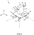
- a Coriolis flowmeter 5 is mounted on a platform 400.
- a case 402 may be provided to enclose the sensor assembly 10 (not visible due to case).
- the platform 400 comprises a gyroscopic sensor 404, which may detect the position and/or acceleration of the platform 400 in three (x, y, z) axes. It should be noted that the platform 400 may be a base upon which the flowmeter 5 is mounted, or may comprise a case, manifold, standoffs, or any other portion of the flowmeter 5, thus obviating the need for a separate mounting stage.
- the gyroscopic sensor 404 is in communication with meter electronics 20.
- An actuator 406X, 406Y, 406Z is coupled to the platform 400, such that the actuator 406X may move the platform 400 in the x plane, the actuator 406Y may move the platform 400 in the y plane, and the actuator 406Z may move the platform 400 in the z plane.
- the actuators 406X, 406Y, 406Z are in communication with meter electronics 20.
- the gyroscopic sensor 404 detects a change in spatial position of the platform 400, and a signal is generated that is sent to meter electronics 20. In response, a desired compensatory motion path that cancels, or at least attenuates, the measured change in spatial position of the platform 400 is calculated.
- a signal is sent from meter electronics 20 to the actuators 406X, 406Y, 406Z such that the motion and position of the platform 400 may be adjusted so to compensate for the non-inertial frame-related spatial position or rate of position change of the platform 400.
- inertial changes detected by the gyroscopic sensor 404 may be utilized to mathematically compensate measured Coriolis bending forces to reduce or eliminate the effect of external inertial forces on the bending modes that are measured in response to process fluid flow through the flowmeter 5. For example, the extra dynamic loads coming from speeding up or slowing down of a vehicle can be detected and compensated for using this embodiment.
- the driver 104 and pickoffs 105, 105' may be replaced with MEMS-based sensors in order to reduce mass and therefore to reduce the dynamic stresses on the tubes while measuring during motion.
- each of the actuators 406X, 406Y, 406Z is illustrated as being disposed in-line with a central axis of the platform 400 (or the center of the flowmeter 5), in an embodiment, one of the actuators may be located at the edge of the platform 400, aligned parallel with the axis defined by said edge. In such an embodiment, the actuator is coupled to the platform 400, such that rotational motion of the actuator is coupled directly to the platform, and rotational motion is conferred directly thereto.
- process line 408 is connected to the flowmeter 5 using a flexible junction 410.
- the flexible junction 410 allows the flowmeter 5 to have a predetermined range of motion that is not constrained by anchoring to a rigid conduit.
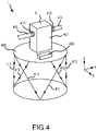
- FIG. 4 illustrates an embodiment of the invention wherein linear actuators 412 are coupled to the platform 400.
- the linear actuators 412 may move the platform 400 in the x plane, the y plane, and the z plane.
- the platform 400 comprises a gyroscopic sensor 404, which may detect the positon and/or acceleration of the platform 400 in three (x, y, z) axes.
- the gyroscopic sensor 404 is in communication with meter electronics 20.
- the linear actuators 412 are in communication with meter electronics 20.
- the gyroscopic sensor 404 detects a change in spatial position of the platform 400, and a signal is generated that is sent to meter electronics 20. In response, a desired compensatory motion path that cancels, or at least attenuates, the measured change in spatial position of the platform 400 is calculated. A signal is sent from meter electronics 20 to the linear actuators 412 such that the motion and position of the platform 400 may be adjusted by either extension or contraction of an actuator so to compensate for the non-inertial frame-related spatial position or rate of position change of the platform 400.
- inertial changes detected by the gyroscopic sensor 404 may be utilized to mathematically compensate measured Coriolis bending forces to reduce or eliminate the effect of external inertial forces on the bending modes that are measured in response to process fluid flow through the flowmeter 5.
- FIGS 3 and 4 show active compensation schemes for dealing with externally applied inertial forces.
- FIG. 5 illustrates a relatively passive approach.
- the Coriolis flowmeter 5 is still mounted on a platform 400, and the platform 400 may comprise a gyroscopic sensor 404 that may detect the position and/or acceleration of the platform 400 in three (x, y, z) axes.
- a gyroscopic sensor is not required.
- the position of the gyroscopic sensor may be such that it is not strictly mounted on the platform 400 itself, but may be on the flowmeter 5, case 402, standoffs, or other appropriate location.
- a gyroscopic sensor 404 may be in communication with meter electronics 20, and inertial changes detected by the gyroscopic sensor 404 may be utilized to mathematically compensate measured Coriolis bending forces to reduce or eliminate the effect of external inertial forces on the bending modes that are measured in response to process fluid flow through the flowmeter 5.
- a gyroscopic gimbal 420 is coupled to the platform 400. In the embodiment illustrated, three gimbals 420 are coupled to the platform 400, and are spaced approximately 120° from each other. The gimbals 420 each comprise a spinning wheel 422 or disc in which the axis of rotation is free to assume any orientation.
- the center of the platform 400 may be mounted on a joint that allows motion in the x, y, and z axis.
- the platform may comprise a case, manifold, standoffs, or any other portion of the flowmeter 5, thus obviating the need for a separate mounting stage. Therefore, case, manifold, standoffs, or any other portion of the flowmeter 5 may be mounted on a joint that allows motion in the x, y, and z axis.
- the platform 400 When mounted on substrate that experiences motion, such as a plane, for example without limitation, as the substrate experiences acceleration or changes roll, pitch, and/or yaw, the platform 400 tends to self-stabilize due to the gimbals 420. Therefore, inertial changes of the substrate are automatically compensated for, and Coriolis bending forces being measured by the flowmeter 5 are not affected by external inertial forces. Therefore, accurate readings of the bending modes that are measured in response to process fluid flow through the flowmeter 5 may be made.
Landscapes
- Engineering & Computer Science (AREA)
- Radar, Positioning & Navigation (AREA)
- Remote Sensing (AREA)
- Physics & Mathematics (AREA)
- General Physics & Mathematics (AREA)
- Fluid Mechanics (AREA)
- Automation & Control Theory (AREA)
- Measuring Volume Flow (AREA)
Description
- The present invention relates to flowmeters, and more particularly to a method and apparatus for determining accurate flow properties at acceleration.
- Vibrating sensors, such as for example, vibrating densitometers and Coriolis flowmeters are generally known, and are used to measure mass flow and other information for materials flowing through a conduit in the flowmeter. Exemplary Coriolis flowmeters are disclosed in
U.S. Patent 4,109,524 ,U.S. Patent 4,491,025 , andRe. 31,450 , all to J.E. Smith et al, see also inUS 2008/0184813 A1 . - These flowmeters have one or more conduits of a straight or curved configuration. Each conduit configuration in a Coriolis mass flowmeter, for example, has a set of natural vibration modes, which may be of simple bending, torsional, or coupled type. Each conduit can be driven to oscillate at a preferred mode.
- Material flows into the flowmeter from a connected pipeline on the inlet side of the flowmeter, is directed through the conduit(s), and exits the flowmeter through the outlet side of the flowmeter. The natural vibration modes of the vibrating system are defined in part by the combined mass of the conduits and the material flowing within the conduits.
- When there is no flow through the flowmeter, a driving force applied to the conduit(s) causes all points along the conduit(s) to oscillate with identical phase or a small "zero offset", which is a time delay measured at zero flow. As material begins to flow through the flowmeter, Coriolis forces cause each point along the conduit(s) to have a different phase. For example, the phase at the inlet end of the flowmeter lags the phase at the centralized driver position, while the phase at the outlet leads the phase at the centralized driver position. Pickoffs on the conduit(s) produce sinusoidal signals representative of the motion of the conduit(s). Signals output from the pickoffs are processed to determine the time delay between the pickoffs. The time delay between the two or more pickoffs is proportional to the mass flow rate of material flowing through the conduit(s).
- Meter electronics connected to the driver generate a drive signal to operate the driver and determine a mass flow rate and other properties of a material from signals received from the pickoffs. The driver may comprise one of many well-known arrangements; however, a magnet and an opposing drive coil have received great success in the flowmeter industry. An alternating current is passed to the drive coil for vibrating the conduit(s) at a desired flow tube amplitude and frequency. It is also known in the art to provide the pickoffs as a magnet and coil arrangement very similar to the driver arrangement. However, while the driver receives a current which induces a motion, the pickoffs can use the motion provided by the driver to induce a voltage. The magnitude of the time delay measured by the pickoffs is very small; often measured in nanoseconds. Therefore, it is necessary to have the transducer output be very accurate.
- Generally, a Coriolis flowmeter can be initially calibrated and a flow calibration factor along with a zero offset can be generated. In use, the flow calibration factor (FCF) can be multiplied by the time delay measured by the pickoffs (ΔT) minus the zero offset (ΔT0) to generate a mass flow rate. Such mass flow calibrations may be represented by two calibration constants, which are equivalent to the slope (FCF) and intercept (zero offset) of a straight line. An example of a mass flow rate equation utilizing a flow calibration factor (FCF) and a zero offset (ΔT0) is described by Equation (1):

- Where:
- ṁ = mass flow rate
- FCF = flow calibration factor
- ΔTmeasured = measured time delay
- ΔT0 = initial zero offset
- Coriolis mass flowmeters are generally used at or near the earth's surface. For measurements in high force applications, mass flow is typically measured using turbine flow meters. Turbine flowmeters lack the requisite accuracy required for the aerospace industry, however.
- For example, the volume of a gallon of fuel will change significantly over certain temperature ranges, but the mass remains the same. The addition or removal of weight on an aircraft affects many performance variables such as takeoff speed, required runway length, cruise altitude, cruise range, optimum cruise speed, landing speed, and landing length required. Full fuel can take up as much as 40% of an aircraft's total weight, which greatly affects flight performance. A standard 747-200 aircraft, for example, has 7 fuel tanks and a fuel capacity of 193,000 liters. At standard density, typical jet fuel weighs about 813 grams per liter. At such conditions, the tanks may be filled such that 156,800 Kg of fuel are onboard. However, if the fuel is hot, such as may be the case in a tropical climate, the aircraft may only receive roughly 149,000 Kg of fuel. Likewise, in a cold climate, such as during an Alaskan winter, the tank may accept 162,000 Kg of fuel. The difference in fuel mass between the hot and cold extremes is approximately 13,000 Kg, which equates to a difference of 1 hour of flight time - or close to 885 Km of range.
- A typical turbine flow meter used in jet engine applications, for example, has an accuracy of around 0.5% to 1%. In some cases, this can amount to an inaccuracy of roughly 900 liters of fuel for a given flight. Besides paying for extra fuel (or conversely not having enough fuel onboard), a rich fuel mixture that results in uncombusted fuel leads to atmospheric pollution and increased environmental impact. Furthermore, the measurement error under inertial forces of 5-10 g, which are typical during flight, can increase error rate by approximately 3%, thus potentially increasing the error already inherent in a turbine flow meter by up to 6-fold. To mitigate such errors, it is common practice to use flow conditioners before the turbine meters and use two or even three flow meters in series. This, of course, adds extra cost, weight, and complexity to the system.
- As a Coriolis flow meter has an accuracy of about 0.05%, using such a meter in an aeronautic setting would improve accuracy and overall flight economics due to reduced fuel-related losses. Furthermore, several factors, such as fuel temperature, the velocity profile of the fuel, bearing friction, viscous drag, fluid density, rotor stability, noise and vibration are far less prone to interfering with system accuracy when using a Coriolis flowmeter as compared to a turbine flow meter.
- Therefore, there is a need in the art for an apparatus and method to accurately measure process fluid flow under high-force conditions. The present invention overcomes the above-noted difficulties and other problems and an advance in the art is achieved. To overcome these difficulties, a Coriolis mass flow meter designed for dynamic applications and related methods are provided. In particular, a flowmeter that compensates and withstands the dynamic loads typical in vehicular and aeronautic applications is presented. The need for flowmeter redundancy and in-line conditioning are eliminated, and system accuracy is improved.
- According to an embodiment, a fluid measurement system is provided. The fluid measurement system comprises a Coriolis flowmeter comprising a meter electronics further comprising a processing system and a storage system. A sensor assembly comprises conduits, wherein the sensor assembly is in communication with meter electronics. A plurality of pickoffs are affixed to the conduits, wherein the plurality of pickoffs is in communication with the meter electronic. A driver is affixed to the conduits, wherein the driver is in communication with the meter electronics. A gyroscopic sensor is in communication with the meter electronics. At least one actuator is coupled to the Coriolis flowmeter. The meter electronics is configured to measure a fluid flow of a process fluid under acceleration through the sensor assembly.
- According to an embodiment, a method of stabilizing a Coriolis flowmeter is provided.
- The method comprises the steps of: determining a preferred orientation of a flowmeter sensor assembly; determining the actual orientation of the flowmeter sensor assembly; determining a difference between the actual orientation and the preferred orientation; and changing the actual orientation of the flowmeter sensor assembly by approximately the difference between the actual orientation and the preferred orientation.
- According to an embodiment, a method of stabilizing a Coriolis flowmeter is provided.
- The method comprises the steps of: coupling a flowmeter sensor assembly to a platform, wherein the platform is pivotable about an x, y, and z axis; coupling at least one gyroscopic gimbal to the platform, wherein the at least one gyroscopic gimbal aids in stabilizing the platform.
- According to an embodiment, a fluid measurement system is provided. The fluid measurement system comprises a Coriolis flowmeter comprising a meter electronics further comprising a processing system and a storage system. A sensor assembly comprises conduits, wherein the sensor assembly is in communication with meter electronics. A plurality of pickoffs are affixed to the conduits, wherein the plurality of pickoffs is in communication with the meter electronics. A driver is affixed to the conduits, wherein the driver is in communication with the meter electronics. At least one gyroscopic gimbal is coupled to the Coriolis flowmeter. A joint allows Coriolis flowmeter motion in the x, y, and z axes. The meter electronics is configured to measure a fluid flow of a process fluid under acceleration through the sensor assembly.
- According to an aspect, a fluid measurement system comprises a Coriolis flowmeter comprising: a meter electronics comprising a processing system and a storage system; a sensor assembly comprising conduits, wherein the sensor assembly is in communication with meter electronics; a plurality of pickoffs affixed to the conduits, wherein the plurality of pickoffs is in communication with the meter electronics; and a driver affixed to the conduits, wherein the driver is in communication with the meter electronics. A gyroscopic sensor is in communication with the meter electronics. At least one actuator is coupled to the Coriolis flowmeter. The meter electronics is configured to measure a fluid flow of a process fluid under acceleration through the sensor assembly.
- Preferably, the at least one actuator is coupled to the Coriolis flowmeter with a platform.
- Preferably, the at least one actuator comprises: a first actuator coupled to the platform, and configured to move the platform about an x axis; a second actuator coupled to the platform, and configured to move the platform about a y axis; and a third actuator coupled to the platform, and configured to move the platform about a z axis.
- Preferably, the first, second, and third actuators are in communication with meter electronics.
- Preferably, the first, second, and third actuators comprise rotary actuators.
- Preferably, the first, second, and third actuators comprise linear actuators.
- Preferably, the fluid measurement system further comprises a flexible junction between the flowmeter and a process line.
- According to an aspect, a method of stabilizing a Coriolis flowmeter comprises the steps of: determining a preferred orientation of a flowmeter sensor assembly; determining the actual orientation of the flowmeter sensor assembly; determining a difference between the actual orientation and the preferred orientation; and changing the actual orientation of the flowmeter sensor assembly by approximately the difference between the actual orientation and the preferred orientation.
- Preferably, the actual orientation is determined with a gyroscopic sensor.
- Preferably, the actual orientation is changed with at least one actuator.
- Preferably, the method of stabilizing a flowmeter comprises the step of coupling the sensor assembly to a platform.
- Preferably, the method of stabilizing a flowmeter comprises the step of coupling at least one actuator to the platform.
- Preferably, the method of stabilizing a flowmeter comprises providing meter electronics in communication with the sensor assembly; connecting meter electronics to a gyroscopic sensor; and connecting meter electronics to at least one actuator.
- Preferably, the method of stabilizing a flowmeter comprises connecting the sensor assembly to a process line with a flexible junction.
- According to an aspect, a method of stabilizing a Coriolis flowmeter, comprising the steps of: coupling a flowmeter sensor assembly to a platform, wherein the platform is pivotable about an x, y, and z axis, and coupling at least one gyroscopic gimbal to the platform, wherein the at least one gyroscopic gimbal aids in stabilizing the platform.
- Preferably, the at least one gyroscopic gimbal comprises three gimbals.
- Preferably, each gimbal is spaced 120° from a neighboring gimbal.
- According to an aspect, a fluid measurement system, comprising: a Coriolis flowmeter comprising: a meter electronics comprising a processing system and a storage system; a sensor assembly comprising conduits, wherein the sensor assembly is in communication with meter electronics; a plurality of pickoffs affixed to the conduits, wherein the plurality of pickoffs is in communication with the meter electronics; and a driver affixed to the conduits, wherein the driver is in communication with the meter electronics. At least one gyroscopic gimbal is coupled to the Coriolis flowmeter. A joint allows Coriolis flowmeter motion in the x, y, and z axes. The meter electronics is configured to measure a fluid flow of a process fluid under acceleration through the sensor assembly.
-
-
FIG. 1 shows a vibrating sensor assembly according to an embodiment; -
FIG. 2 shows meter electronics according to an embodiment; -
FIG. 3 illustrates a flowmeter according to an embodiment; -
FIG. 4 illustrates a flowmeter according to an alternate embodiment; and -
FIG. 5 illustrates a flowmeter according to yet another embodiment. -
FIGS. 1-5 and the following description depict specific examples to teach those skilled in the art how to make and use the best mode of the invention. For the purpose of teaching inventive principles, some conventional aspects have been simplified or omitted. Those skilled in the art will appreciate variations from these examples that fall within the scope of the invention, and will appreciate that the features described below can be combined in various ways to form multiple variations of the invention. As a result, the invention is not limited to the specific examples described below, but only by the claims and their equivalents. -
FIG. 1 illustrates an example of aflowmeter 5 in the form of a Coriolis flowmeter comprising a sensor assembly 10 and one ormore meter electronics 20. The one ormore meter electronics 20 are connected to sensor assembly 10 to measure a characteristic of a flowing material, such as, for example, density, pressure, mass flow rate, volume flow rate, totalized mass flow, temperature, and other information. - The sensor assembly 10 includes a pair of
flanges 101 and 101',manifolds 102 and 102', andconduits Manifolds 102, 102' are affixed to opposing ends of theconduits Flanges 101 and 101' of the present example are affixed tomanifolds 102 and 102'.Manifolds 102 and 102' of the present example are affixed to opposite ends ofspacer 106. Thespacer 106 maintains the spacing betweenmanifolds 102 and 102' in the present example to prevent undesired vibrations inconduits conduits manifolds 102 and 102' in an essentially parallel fashion. When the sensor assembly 10 is inserted into a pipeline system (not shown) which carries the flowing material, the material enters sensor assembly 10 throughflange 101, passes throughinlet manifold 102 where the total amount of material is directed to enterconduits conduits - The sensor assembly 10 includes a
driver 104. Thedriver 104 is affixed toconduits driver 104 can vibrate theconduits driver 104 includes a first driver component (not shown) affixed toconduit 103A, and a second driver component (not shown) affixed toconduit 103B. Thedriver 104 may comprise one of many well-known arrangements, such as a magnet mounted to theconduit 103A and an opposing coil mounted to theconduit 103B. - In the present example, the drive mode is the first out of phase bending mode, and the
conduits inlet manifold 102 and outlet manifold 102' so as to provide a balanced system having substantially the same mass distribution, moments of inertia, and elastic moduli about bending axes W-W and W'-W', respectively. In the present example, where the drive mode is the first out of phase bending mode, theconduits driver 104 in opposite directions about their respective bending axes W-W and W'-W'. A drive signal in the form of an alternating current can be provided by one ormore meter electronics 20, such as for example vialead 110, and passed through the coil to cause bothconduits - The sensor assembly 10 shown includes a pair of
pickoffs 105, 105' that are affixed toconduits conduit 103A, and a second pickoff component (not shown) is located onconduit 103B. In the embodiment depicted, thepickoffs 105, 105' may be electromagnetic detectors, for example-pickoff magnets and pickoff coils that produce pickoff signals that represent the velocity and position of theconduits pickoffs 105, 105' may supply pickoff signals to the one or more meter electronics viapathways 111, 111'. Those of ordinary skill in the art will appreciate that the motion of theconduits conduits - It should be appreciated that while the sensor assembly 10 described above comprises a dual flow conduit flowmeter, it is well within the scope of the present invention to implement a single conduit flowmeter. Furthermore, while the
flow conduits - In the example shown in
FIG. 1 , the one ormore meter electronics 20 receive the pickoff signals from thepickoffs 105, 105'.Path 26 provides an input and an output means that allows one ormore meter electronics 20 to interface with an operator. The one ormore meter electronics 20 measure a characteristic of a flowing material, such as, for example, a phase difference, a frequency, a time delay, a density, a mass flow rate, a volume flow rate, a totalized mass flow, a temperature, a meter verification, pressure, and other information. More particularly, the one ormore meter electronics 20 receive one or more signals, for example, frompickoffs 105, 105', and one ormore temperature sensors 107, such as a resistive temperature detector (RTD), and use this information to measure a characteristic of a flowing material. - The techniques by which vibrating sensor assemblies, such as, for example, Coriolis flowmeters or densitometers, measure a characteristic of a flowing material are well understood; therefore, a more detailed discussion is omitted for brevity of this description.
-
FIG. 2 shows themeter electronics 20 according to an embodiment. Themeter electronics 20 can include aninterface 301 and a processing system 303. The processing system 303 may include a storage system 304. The storage system 304 may comprise an internal memory and/or may comprise an external memory. Themeter electronics 20 can generate adrive signal 311 and supply thedrive signal 311 to thedriver 104. In addition, themeter electronics 20 can receivesensor signals 310 from thepickoffs 105, 105', such as pickoff/velocity sensor signals, strain signals, optical signals, or any other signals or sensors known in the art. In some embodiments, the sensor signals 310 can be received from thedriver 104. Themeter electronics 20 can operate as a densitometer or can operate as a mass flowmeter, including operating as a Coriolis flowmeter. It should be appreciated that themeter electronics 20 may also operate as some other type of vibrating sensor assembly and the particular examples provided should not limit the scope of the present invention. Themeter electronics 20 can process the sensor signals 310 in order to obtain flow characteristics of the material flowing through theflow conduits meter electronics 20 may receive atemperature signal 312 from one or more resistive temperature detector (RTD) sensors orother temperature sensors 107, for example. - The
interface 301 can receive the sensor signals 310 from thedriver 104 orpickoffs 105, 105', via leads 110, 111, 111'. Theinterface 301 may perform any necessary or desired signal conditioning, such as any manner of formatting, amplification, buffering, etc. Alternatively, some or all of the signal conditioning can be performed in the processing system 303. In addition, theinterface 301 can enable communications between themeter electronics 20 and external devices. Theinterface 301 can be capable of any manner of electronic, optical, or wireless communication. - The
interface 301 in one embodiment can include adigitizer 302, wherein the sensor signal comprises an analog sensor signal. Thedigitizer 302 can sample and digitize the analog sensor signal and produce a digital sensor signal. Thedigitizer 302 can also perform any needed decimation, wherein the digital sensor signal is decimated in order to reduce the amount of signal processing needed and to reduce the processing time. - The processing system 303 can conduct operations of the
meter electronics 20 and process flow measurements from the sensor assembly 10. The processing system 303 can execute one or more processing routines, such as ageneral operating routine 314. - The processing system 303 can comprise a general purpose computer, a micro-processing system, a logic circuit, or some other general purpose or customized processing device. The processing system 303 can be distributed among multiple processing devices. The processing system 303 can include any manner of integral or independent electronic storage medium, such as storage system 304.
- The processing system 303 processes the sensor signals 310 in order to generate a
drive signal 311, among other things. Thedrive signal 311 is supplied to thedriver 104 vialead 110 in order to vibrate the associated flow tube(s), such as theconduits FIG. 1 . - A
motion compensation routine 316 communicates with and processes data received from at least onegyroscopic sensor 404. Meter electronics may calibrate, update, and send and receive data to and from thegyroscopic sensor 404. Positional signals and motion signals from thegyroscopic sensor 404 may be processed via themotion compensation routine 316 to generate corresponding signals foractuators 406X, 406Y, 406Z, and 412, such that compensatory motion and position may be obtained, as will be described in greater detail below. Furthermore, positional signals and motion signals from thegyroscopic sensor 404 may be processed via themotion compensation routine 316 to adjust mass flow rate, density, volume flow rate, and other measured values, to mathematically compensate measured Coriolis bending forces so to reduce or eliminate the effect of external inertial forces on the bending modes that are measured in response to process fluid flow through theflowmeter 5. In an embodiment, the preferred or starting orientation of the flowmeter is predetermined, and this position is saved in meter electronics. In an embodiment, thegyroscopic sensor 404 determines the actual orientation of theflowmeter 5, and a difference between the actual orientation and the preferred orientation is calculated. This difference is calculated by meter electronics or by external electronics, and the actual orientation of the flowmeter may be altered by approximately the difference between the actual orientation and the preferred orientation. This may be effectuated by actuators, as will be discussed below. This compensates for motion, and places theflowmeter 5 in approximately the preferred orientation. Besides position, the rate of position change may be calculated, and theflowmeter 5 may be moved at a rate that at least partially counteracts the forces that accompany a positional change. The rate and positional changes may be calculated withmeter electronics 20 or external electronics. - It should be understood that the
meter electronics 20 may include various other components and functions that are generally known in the art. These additional features are omitted from the description and the figures for the purpose of brevity. Therefore, the present invention should not be limited to the specific embodiments shown and discussed. - Turning to
FIGS. 3-5 , embodiments offluid measurement systems 3 havingflowmeters 5 are provided that are suitable for high-force applications, such as in vehicular or aeronautic applications, for example without limitation. In the embodiments, the Coriolis flow meters measure flow tube motion from thepick offs 105, 105', which are attached to theflow tubes flow tube - With particular reference to
FIG. 3 , aCoriolis flowmeter 5 is mounted on aplatform 400. Acase 402 may be provided to enclose the sensor assembly 10 (not visible due to case). Theplatform 400 comprises agyroscopic sensor 404, which may detect the position and/or acceleration of theplatform 400 in three (x, y, z) axes. It should be noted that theplatform 400 may be a base upon which theflowmeter 5 is mounted, or may comprise a case, manifold, standoffs, or any other portion of theflowmeter 5, thus obviating the need for a separate mounting stage. Thegyroscopic sensor 404 is in communication withmeter electronics 20. An actuator 406X, 406Y, 406Z is coupled to theplatform 400, such that the actuator 406X may move theplatform 400 in the x plane, the actuator 406Y may move theplatform 400 in the y plane, and the actuator 406Z may move theplatform 400 in the z plane. The actuators 406X, 406Y, 406Z are in communication withmeter electronics 20. In an embodiment, thegyroscopic sensor 404 detects a change in spatial position of theplatform 400, and a signal is generated that is sent tometer electronics 20. In response, a desired compensatory motion path that cancels, or at least attenuates, the measured change in spatial position of theplatform 400 is calculated. A signal is sent frommeter electronics 20 to the actuators 406X, 406Y, 406Z such that the motion and position of theplatform 400 may be adjusted so to compensate for the non-inertial frame-related spatial position or rate of position change of theplatform 400. Furthermore, inertial changes detected by thegyroscopic sensor 404 may be utilized to mathematically compensate measured Coriolis bending forces to reduce or eliminate the effect of external inertial forces on the bending modes that are measured in response to process fluid flow through theflowmeter 5. For example, the extra dynamic loads coming from speeding up or slowing down of a vehicle can be detected and compensated for using this embodiment. - In order to reduce the effects of external inertial interference, in an embodiment, the
driver 104 andpickoffs 105, 105' may be replaced with MEMS-based sensors in order to reduce mass and therefore to reduce the dynamic stresses on the tubes while measuring during motion. - Although each of the actuators 406X, 406Y, 406Z is illustrated as being disposed in-line with a central axis of the platform 400 (or the center of the flowmeter 5), in an embodiment, one of the actuators may be located at the edge of the
platform 400, aligned parallel with the axis defined by said edge. In such an embodiment, the actuator is coupled to theplatform 400, such that rotational motion of the actuator is coupled directly to the platform, and rotational motion is conferred directly thereto. - It should be noted that the
process line 408 is connected to theflowmeter 5 using aflexible junction 410. Theflexible junction 410 allows theflowmeter 5 to have a predetermined range of motion that is not constrained by anchoring to a rigid conduit. - The actuators 406X, 406Y, 406Z illustrated in
FIG. 3 are rotary in nature, and confer a rotational motion through an axis of theplatform 400.FIG. 4 illustrates an embodiment of the invention whereinlinear actuators 412 are coupled to theplatform 400. In the same vein as the embodiment shown inFIG. 3 , thelinear actuators 412 may move theplatform 400 in the x plane, the y plane, and the z plane. Theplatform 400 comprises agyroscopic sensor 404, which may detect the positon and/or acceleration of theplatform 400 in three (x, y, z) axes. Thegyroscopic sensor 404 is in communication withmeter electronics 20. Thelinear actuators 412 are in communication withmeter electronics 20. In an embodiment, thegyroscopic sensor 404 detects a change in spatial position of theplatform 400, and a signal is generated that is sent tometer electronics 20. In response, a desired compensatory motion path that cancels, or at least attenuates, the measured change in spatial position of theplatform 400 is calculated. A signal is sent frommeter electronics 20 to thelinear actuators 412 such that the motion and position of theplatform 400 may be adjusted by either extension or contraction of an actuator so to compensate for the non-inertial frame-related spatial position or rate of position change of theplatform 400. Like other embodiments, inertial changes detected by thegyroscopic sensor 404 may be utilized to mathematically compensate measured Coriolis bending forces to reduce or eliminate the effect of external inertial forces on the bending modes that are measured in response to process fluid flow through theflowmeter 5. - The embodiments illustrated in
FIGS 3 and4 show active compensation schemes for dealing with externally applied inertial forces.FIG. 5 illustrates a relatively passive approach. In this, and related embodiments, theCoriolis flowmeter 5 is still mounted on aplatform 400, and theplatform 400 may comprise agyroscopic sensor 404 that may detect the position and/or acceleration of theplatform 400 in three (x, y, z) axes. For this embodiment, however, a gyroscopic sensor is not required. It should be noted that for all embodiments, the position of the gyroscopic sensor may be such that it is not strictly mounted on theplatform 400 itself, but may be on theflowmeter 5,case 402, standoffs, or other appropriate location. Agyroscopic sensor 404 may be in communication withmeter electronics 20, and inertial changes detected by thegyroscopic sensor 404 may be utilized to mathematically compensate measured Coriolis bending forces to reduce or eliminate the effect of external inertial forces on the bending modes that are measured in response to process fluid flow through theflowmeter 5. Agyroscopic gimbal 420 is coupled to theplatform 400. In the embodiment illustrated, threegimbals 420 are coupled to theplatform 400, and are spaced approximately 120° from each other. Thegimbals 420 each comprise aspinning wheel 422 or disc in which the axis of rotation is free to assume any orientation. When rotating, the orientation of this axis of thespinning wheel 422 is unaffected by tilting or rotation of the mounting 424, due to the well-known property of conservation of angular momentum. This property aids in maintaining the orientation of thegimbal 420. The center of theplatform 400 may be mounted on a joint that allows motion in the x, y, and z axis. Alternatively, in instances without a mounting state, the platform may comprise a case, manifold, standoffs, or any other portion of theflowmeter 5, thus obviating the need for a separate mounting stage. Therefore, case, manifold, standoffs, or any other portion of theflowmeter 5 may be mounted on a joint that allows motion in the x, y, and z axis. When mounted on substrate that experiences motion, such as a plane, for example without limitation, as the substrate experiences acceleration or changes roll, pitch, and/or yaw, theplatform 400 tends to self-stabilize due to thegimbals 420. Therefore, inertial changes of the substrate are automatically compensated for, and Coriolis bending forces being measured by theflowmeter 5 are not affected by external inertial forces. Therefore, accurate readings of the bending modes that are measured in response to process fluid flow through theflowmeter 5 may be made. - The detailed descriptions of the above embodiments are not exhaustive descriptions of all embodiments contemplated by the inventors to be within the scope of the invention.
- Accordingly, the scope of the invention should be determined from the following claims.
Claims (16)
- A fluid measurement system (3), comprising:
a Coriolis flowmeter (5) comprising:a meter electronics (20) comprising a processing system (303) and a storage system (304);a sensor assembly (10) comprising conduits (103A, 103B), wherein the sensor assembly (10) is in communication with meter electronics (20);a plurality of pickoffs (105, 105') affixed to the conduits (103A, 103B), wherein the plurality of pickoffs (105, 105') is in communication with the meter electronics (20); anda driver (104) affixed to the conduits (103A, 103B), wherein the driver (104) is in communication with the meter electronics (20);wherein the meter electronics (20) is configured to measure a fluid flow of a process fluid under acceleration through the sensor assembly (10), andcharacterized in that the fluid measurement system (3) comprises:a gyroscopic sensor in communication with the meter electronics (20); andat least one actuator (406X, 406Y, 406Z, 412) coupled to the Coriolis flowmeter (5). - The fluid measurement system (3) of Claim 1, wherein the at least one actuator (406X, 406Y, 406Z, 412) is coupled to the Coriolis flowmeter with a platform (400).
- The fluid measurement system (3) of Claim 1, wherein the at least one actuator (406X, 406Y, 406Z, 412) comprises:a first actuator (406X, 412) coupled to the platform (400), and configured to move the platform (400) about a first axis;a second actuator (406Y, 412) coupled to the platform (400), and configured to move the platform (400) about a second axis; anda third actuator (406Z, 412) coupled to the platform (400), and configured to move the platform (400) about a third axis.
- The fluid measurement system (3) of Claim 3, wherein the first, second, and third actuators (406X, 406Y, 406Z, 412) are in communication with meter electronics (20).
- The fluid measurement system (3) of Claim 1, further comprising a flexible junction (410) between the flowmeter (5) and a process line (408).
- A method of stabilizing a Coriolis flowmeter, characterized by:
the steps of:determining a preferred orientation of a flowmeter sensor assembly;determining the actual orientation of the flowmeter sensor assembly;determining a difference between the actual orientation and the preferred orientation; andchanging the actual orientation of the flowmeter sensor assembly by approximately the difference between the actual orientation and the preferred orientation. - The method of stabilizing a flowmeter of Claim 6, wherein the actual orientation is determined with a gyroscopic sensor.
- The method of stabilizing a flowmeter of Claim 6, wherein the actual orientation is changed with at least one actuator.
- The method of stabilizing a flowmeter of Claim 6, comprising the step of coupling the sensor assembly to a platform.
- The method of stabilizing a flowmeter of Claim 9, comprising the step of coupling at least one actuator to the platform.
- The method of stabilizing a flowmeter of Claim 6, characterized by the steps of:providing meter electronics in communication with the sensor assembly;connecting meter electronics to a gyroscopic sensor; andconnecting meter electronics to at least one actuator.
- The method of stabilizing a flowmeter of Claim 11, comprising the steps of connecting the sensor assembly to a process line with a flexible junction.
- A method of stabilizing a Coriolis flowmeter, comprising the steps of:coupling a flowmeter sensor assembly to a platform, wherein the platform is pivotable about three axes; andcoupling at least one gyroscopic gimbal to the platform,wherein the at least one gyroscopic gimbal aids in stabilizing the platform.
- The method of stabilizing a flowmeter of Claim 13, wherein the at least one gyroscopic gimbal comprises three gimbals.
- The method of stabilizing a flowmeter of Claim 14, wherein each gimbal is spaced 120° from a neighboring gimbal.
- A fluid measurement system (3), comprising:
a Coriolis flowmeter (5) comprising:a meter electronics (20) comprising a processing system (303) and a storage system (304);a sensor assembly (10) comprising conduits (103A, 103B), wherein the sensor assembly (10) is in communication with meter electronics (20);a plurality of pickoffs (105, 105') affixed to the conduits (103A, 103B), wherein the plurality of pickoffs (105, 105') is in communication with the meter electronics (20); anda driver (104) affixed to the conduits (103A, 103B), wherein the driver (104) is in communication with the meter electronics (20);wherein the meter electronics (20) is configured to measure a fluid flow of a process fluid under acceleration through the sensor assembly (10), andcharacterized in that the fluid measurement system (3) comprises:at least one gyroscopic gimbal (420) coupled to the Coriolis flowmeter (5); anda joint that allows Coriolis flowmeter (5) motion in three axes.
Applications Claiming Priority (1)
| Application Number | Priority Date | Filing Date | Title |
|---|---|---|---|
| PCT/US2017/039446 WO2019005008A1 (en) | 2017-06-27 | 2017-06-27 | Force compensation for a vibrating flowmeter and related method |
Publications (2)
| Publication Number | Publication Date |
|---|---|
| EP3645983A1 EP3645983A1 (en) | 2020-05-06 |
| EP3645983B1 true EP3645983B1 (en) | 2022-08-24 |
Family
ID=59285396
Family Applications (1)
| Application Number | Title | Priority Date | Filing Date |
|---|---|---|---|
| EP17735756.3A Active EP3645983B1 (en) | 2017-06-27 | 2017-06-27 | Force compensation for a vibrating flowmeter and related method |
Country Status (5)
| Country | Link |
|---|---|
| US (1) | US11060897B2 (en) |
| EP (1) | EP3645983B1 (en) |
| JP (1) | JP6949151B2 (en) |
| CN (1) | CN110809709B (en) |
| WO (1) | WO2019005008A1 (en) |
Families Citing this family (3)
| Publication number | Priority date | Publication date | Assignee | Title |
|---|---|---|---|---|
| DE102019123344B3 (en) * | 2019-08-30 | 2021-02-25 | Endress+Hauser Flowtec Ag | Coriolis measuring sensor and Coriolis measuring device with a device for determining the age of magnets of a sensor or exciter and a method for determining the age |
| DE102019126883A1 (en) * | 2019-10-07 | 2021-04-08 | Endress+Hauser Flowtec Ag | Method for monitoring a measuring device system |
| US12455220B2 (en) | 2019-11-13 | 2025-10-28 | Micro Motion, Inc. | Detecting an orientation of a vibratory meter and compensating a measurement based on the detected orientation |
Citations (3)
| Publication number | Priority date | Publication date | Assignee | Title |
|---|---|---|---|---|
| US3638502A (en) * | 1969-12-01 | 1972-02-01 | Westinghouse Canada Ltd | Stabilized camera mount |
| US4989466A (en) * | 1989-08-02 | 1991-02-05 | Goodman Ronald C | Gyroscopically stabilized sensor positioning system |
| US20080184813A1 (en) * | 2005-03-29 | 2008-08-07 | Micro Motion, Inc. | Coriolis Flow Meter and Method for Determining Flow Characteristics |
Family Cites Families (12)
| Publication number | Priority date | Publication date | Assignee | Title |
|---|---|---|---|---|
| US4109524A (en) | 1975-06-30 | 1978-08-29 | S & F Associates | Method and apparatus for mass flow rate measurement |
| USRE31450E (en) | 1977-07-25 | 1983-11-29 | Micro Motion, Inc. | Method and structure for flow measurement |
| US4491025A (en) | 1982-11-03 | 1985-01-01 | Micro Motion, Inc. | Parallel path Coriolis mass flow rate meter |
| EP0658746A1 (en) * | 1993-12-15 | 1995-06-21 | Shell Internationale Researchmaatschappij B.V. | Device for carrying equipment through a conduit |
| US6314820B1 (en) * | 1999-02-10 | 2001-11-13 | Micro Motion, Inc. | Lateral mode stabilizer for Coriolis flowmeter |
| US6520028B1 (en) * | 2000-11-28 | 2003-02-18 | Micro Motion, Inc. | Gyroscopic mass flowmeter |
| JP3689738B2 (en) * | 2002-02-26 | 2005-08-31 | 独立行政法人産業技術総合研究所 | Coriolis flow meter |
| US7628083B2 (en) * | 2004-04-16 | 2009-12-08 | Micro Motion, Inc. | Method and apparatus for force balancing |
| US7784359B2 (en) * | 2008-04-17 | 2010-08-31 | Rosemount Aerospace Inc. | Coriolis effect mass flow meter and gyroscope |
| WO2012005734A1 (en) * | 2010-07-09 | 2012-01-12 | Micro Motion, Inc. | A vibrating meter including a damped meter component |
| DE102011119980A1 (en) * | 2011-12-02 | 2013-06-06 | Krohne Ag | Coriolis mass flowmeter |
| DE102015122439A1 (en) * | 2015-12-21 | 2017-06-22 | Endress + Hauser Flowtec Ag | Flowmeter with gyroscopic sensor |
-
2017
- 2017-06-27 CN CN201780092718.XA patent/CN110809709B/en active Active
- 2017-06-27 EP EP17735756.3A patent/EP3645983B1/en active Active
- 2017-06-27 WO PCT/US2017/039446 patent/WO2019005008A1/en not_active Ceased
- 2017-06-27 US US16/617,723 patent/US11060897B2/en active Active
- 2017-06-27 JP JP2019572155A patent/JP6949151B2/en active Active
Patent Citations (3)
| Publication number | Priority date | Publication date | Assignee | Title |
|---|---|---|---|---|
| US3638502A (en) * | 1969-12-01 | 1972-02-01 | Westinghouse Canada Ltd | Stabilized camera mount |
| US4989466A (en) * | 1989-08-02 | 1991-02-05 | Goodman Ronald C | Gyroscopically stabilized sensor positioning system |
| US20080184813A1 (en) * | 2005-03-29 | 2008-08-07 | Micro Motion, Inc. | Coriolis Flow Meter and Method for Determining Flow Characteristics |
Also Published As
| Publication number | Publication date |
|---|---|
| WO2019005008A1 (en) | 2019-01-03 |
| US11060897B2 (en) | 2021-07-13 |
| CN110809709A (en) | 2020-02-18 |
| CN110809709B (en) | 2022-02-11 |
| JP2020525788A (en) | 2020-08-27 |
| US20200109979A1 (en) | 2020-04-09 |
| JP6949151B2 (en) | 2021-10-13 |
| EP3645983A1 (en) | 2020-05-06 |
Similar Documents
| Publication | Publication Date | Title |
|---|---|---|
| KR102248131B1 (en) | Flowmeter calibration method and related devices | |
| EP2464950B1 (en) | Method and meter electronics for determining a zero offset in a vibrating flow meter | |
| KR102042009B1 (en) | Apparatus for applying a variable zero algorithm in a vibrating flowmeter and related method | |
| EP2771656B1 (en) | Collocated sensor for a vibrating fluid meter | |
| EP4097427B1 (en) | Method of correcting flow meter variable | |
| EP3645983B1 (en) | Force compensation for a vibrating flowmeter and related method | |
| JP2017525947A (en) | Fluid momentum detection method and related apparatus | |
| EP3411672B1 (en) | Pressure compensation for a vibrating flowmeter and related method | |
| HU225071B1 (en) | Combined mass flow meter device and method for measuring mass flow of a non solid medium | |
| HK40024520B (en) | Force compensation for a vibrating flowmeter and related method | |
| HK40024520A (en) | Force compensation for a vibrating flowmeter and related method | |
| EP3837501B1 (en) | Determining a decay characteristic of a meter assembly | |
| US20250180384A1 (en) | Mode excitation detection for a vibratory flowmeter and related methods | |
| HK1261585A1 (en) | Pressure compensation for a vibrating flowmeter and related method | |
| HK40050711A (en) | Determining a decay characteristic of a meter assembly | |
| HK1135464B (en) | Meter electronics and methods for geometric thermal compensation in a flow meter | |
| HK1135464A1 (en) | Meter electronics and methods for geometric thermal compensation in a flow meter |
Legal Events
| Date | Code | Title | Description |
|---|---|---|---|
| STAA | Information on the status of an ep patent application or granted ep patent |
Free format text: STATUS: UNKNOWN |
|
| STAA | Information on the status of an ep patent application or granted ep patent |
Free format text: STATUS: THE INTERNATIONAL PUBLICATION HAS BEEN MADE |
|
| PUAI | Public reference made under article 153(3) epc to a published international application that has entered the european phase |
Free format text: ORIGINAL CODE: 0009012 |
|
| STAA | Information on the status of an ep patent application or granted ep patent |
Free format text: STATUS: REQUEST FOR EXAMINATION WAS MADE |
|
| 17P | Request for examination filed |
Effective date: 20200127 |
|
| AK | Designated contracting states |
Kind code of ref document: A1 Designated state(s): AL AT BE BG CH CY CZ DE DK EE ES FI FR GB GR HR HU IE IS IT LI LT LU LV MC MK MT NL NO PL PT RO RS SE SI SK SM TR |
|
| AX | Request for extension of the european patent |
Extension state: BA ME |
|
| DAV | Request for validation of the european patent (deleted) | ||
| DAX | Request for extension of the european patent (deleted) | ||
| GRAP | Despatch of communication of intention to grant a patent |
Free format text: ORIGINAL CODE: EPIDOSNIGR1 |
|
| STAA | Information on the status of an ep patent application or granted ep patent |
Free format text: STATUS: GRANT OF PATENT IS INTENDED |
|
| INTG | Intention to grant announced |
Effective date: 20220314 |
|
| GRAS | Grant fee paid |
Free format text: ORIGINAL CODE: EPIDOSNIGR3 |
|
| GRAA | (expected) grant |
Free format text: ORIGINAL CODE: 0009210 |
|
| STAA | Information on the status of an ep patent application or granted ep patent |
Free format text: STATUS: THE PATENT HAS BEEN GRANTED |
|
| AK | Designated contracting states |
Kind code of ref document: B1 Designated state(s): AL AT BE BG CH CY CZ DE DK EE ES FI FR GB GR HR HU IE IS IT LI LT LU LV MC MK MT NL NO PL PT RO RS SE SI SK SM TR |
|
| REG | Reference to a national code |
Ref country code: CH Ref legal event code: EP |
|
| REG | Reference to a national code |
Ref country code: DE Ref legal event code: R096 Ref document number: 602017060991 Country of ref document: DE |
|
| REG | Reference to a national code |
Ref country code: IE Ref legal event code: FG4D |
|
| REG | Reference to a national code |
Ref country code: AT Ref legal event code: REF Ref document number: 1513954 Country of ref document: AT Kind code of ref document: T Effective date: 20220915 |
|
| REG | Reference to a national code |
Ref country code: LT Ref legal event code: MG9D |
|
| REG | Reference to a national code |
Ref country code: NL Ref legal event code: MP Effective date: 20220824 |
|
| PG25 | Lapsed in a contracting state [announced via postgrant information from national office to epo] |
Ref country code: SE Free format text: LAPSE BECAUSE OF FAILURE TO SUBMIT A TRANSLATION OF THE DESCRIPTION OR TO PAY THE FEE WITHIN THE PRESCRIBED TIME-LIMIT Effective date: 20220824 Ref country code: RS Free format text: LAPSE BECAUSE OF FAILURE TO SUBMIT A TRANSLATION OF THE DESCRIPTION OR TO PAY THE FEE WITHIN THE PRESCRIBED TIME-LIMIT Effective date: 20220824 Ref country code: PT Free format text: LAPSE BECAUSE OF FAILURE TO SUBMIT A TRANSLATION OF THE DESCRIPTION OR TO PAY THE FEE WITHIN THE PRESCRIBED TIME-LIMIT Effective date: 20221226 Ref country code: NO Free format text: LAPSE BECAUSE OF FAILURE TO SUBMIT A TRANSLATION OF THE DESCRIPTION OR TO PAY THE FEE WITHIN THE PRESCRIBED TIME-LIMIT Effective date: 20221124 Ref country code: NL Free format text: LAPSE BECAUSE OF FAILURE TO SUBMIT A TRANSLATION OF THE DESCRIPTION OR TO PAY THE FEE WITHIN THE PRESCRIBED TIME-LIMIT Effective date: 20220824 Ref country code: LV Free format text: LAPSE BECAUSE OF FAILURE TO SUBMIT A TRANSLATION OF THE DESCRIPTION OR TO PAY THE FEE WITHIN THE PRESCRIBED TIME-LIMIT Effective date: 20220824 Ref country code: LT Free format text: LAPSE BECAUSE OF FAILURE TO SUBMIT A TRANSLATION OF THE DESCRIPTION OR TO PAY THE FEE WITHIN THE PRESCRIBED TIME-LIMIT Effective date: 20220824 Ref country code: FI Free format text: LAPSE BECAUSE OF FAILURE TO SUBMIT A TRANSLATION OF THE DESCRIPTION OR TO PAY THE FEE WITHIN THE PRESCRIBED TIME-LIMIT Effective date: 20220824 |
|
| REG | Reference to a national code |
Ref country code: AT Ref legal event code: MK05 Ref document number: 1513954 Country of ref document: AT Kind code of ref document: T Effective date: 20220824 |
|
| PG25 | Lapsed in a contracting state [announced via postgrant information from national office to epo] |
Ref country code: PL Free format text: LAPSE BECAUSE OF FAILURE TO SUBMIT A TRANSLATION OF THE DESCRIPTION OR TO PAY THE FEE WITHIN THE PRESCRIBED TIME-LIMIT Effective date: 20220824 Ref country code: IS Free format text: LAPSE BECAUSE OF FAILURE TO SUBMIT A TRANSLATION OF THE DESCRIPTION OR TO PAY THE FEE WITHIN THE PRESCRIBED TIME-LIMIT Effective date: 20221224 Ref country code: HR Free format text: LAPSE BECAUSE OF FAILURE TO SUBMIT A TRANSLATION OF THE DESCRIPTION OR TO PAY THE FEE WITHIN THE PRESCRIBED TIME-LIMIT Effective date: 20220824 Ref country code: GR Free format text: LAPSE BECAUSE OF FAILURE TO SUBMIT A TRANSLATION OF THE DESCRIPTION OR TO PAY THE FEE WITHIN THE PRESCRIBED TIME-LIMIT Effective date: 20221125 |
|
| PG25 | Lapsed in a contracting state [announced via postgrant information from national office to epo] |
Ref country code: SM Free format text: LAPSE BECAUSE OF FAILURE TO SUBMIT A TRANSLATION OF THE DESCRIPTION OR TO PAY THE FEE WITHIN THE PRESCRIBED TIME-LIMIT Effective date: 20220824 Ref country code: RO Free format text: LAPSE BECAUSE OF FAILURE TO SUBMIT A TRANSLATION OF THE DESCRIPTION OR TO PAY THE FEE WITHIN THE PRESCRIBED TIME-LIMIT Effective date: 20220824 Ref country code: ES Free format text: LAPSE BECAUSE OF FAILURE TO SUBMIT A TRANSLATION OF THE DESCRIPTION OR TO PAY THE FEE WITHIN THE PRESCRIBED TIME-LIMIT Effective date: 20220824 Ref country code: DK Free format text: LAPSE BECAUSE OF FAILURE TO SUBMIT A TRANSLATION OF THE DESCRIPTION OR TO PAY THE FEE WITHIN THE PRESCRIBED TIME-LIMIT Effective date: 20220824 Ref country code: CZ Free format text: LAPSE BECAUSE OF FAILURE TO SUBMIT A TRANSLATION OF THE DESCRIPTION OR TO PAY THE FEE WITHIN THE PRESCRIBED TIME-LIMIT Effective date: 20220824 Ref country code: AT Free format text: LAPSE BECAUSE OF FAILURE TO SUBMIT A TRANSLATION OF THE DESCRIPTION OR TO PAY THE FEE WITHIN THE PRESCRIBED TIME-LIMIT Effective date: 20220824 |
|
| REG | Reference to a national code |
Ref country code: DE Ref legal event code: R097 Ref document number: 602017060991 Country of ref document: DE |
|
| PG25 | Lapsed in a contracting state [announced via postgrant information from national office to epo] |
Ref country code: SK Free format text: LAPSE BECAUSE OF FAILURE TO SUBMIT A TRANSLATION OF THE DESCRIPTION OR TO PAY THE FEE WITHIN THE PRESCRIBED TIME-LIMIT Effective date: 20220824 Ref country code: EE Free format text: LAPSE BECAUSE OF FAILURE TO SUBMIT A TRANSLATION OF THE DESCRIPTION OR TO PAY THE FEE WITHIN THE PRESCRIBED TIME-LIMIT Effective date: 20220824 |
|
| PG25 | Lapsed in a contracting state [announced via postgrant information from national office to epo] |
Ref country code: AL Free format text: LAPSE BECAUSE OF FAILURE TO SUBMIT A TRANSLATION OF THE DESCRIPTION OR TO PAY THE FEE WITHIN THE PRESCRIBED TIME-LIMIT Effective date: 20220824 |
|
| PLBE | No opposition filed within time limit |
Free format text: ORIGINAL CODE: 0009261 |
|
| STAA | Information on the status of an ep patent application or granted ep patent |
Free format text: STATUS: NO OPPOSITION FILED WITHIN TIME LIMIT |
|
| P01 | Opt-out of the competence of the unified patent court (upc) registered |
Effective date: 20230530 |
|
| 26N | No opposition filed |
Effective date: 20230525 |
|
| PG25 | Lapsed in a contracting state [announced via postgrant information from national office to epo] |
Ref country code: SI Free format text: LAPSE BECAUSE OF FAILURE TO SUBMIT A TRANSLATION OF THE DESCRIPTION OR TO PAY THE FEE WITHIN THE PRESCRIBED TIME-LIMIT Effective date: 20220824 |
|
| PG25 | Lapsed in a contracting state [announced via postgrant information from national office to epo] |
Ref country code: MC Free format text: LAPSE BECAUSE OF FAILURE TO SUBMIT A TRANSLATION OF THE DESCRIPTION OR TO PAY THE FEE WITHIN THE PRESCRIBED TIME-LIMIT Effective date: 20220824 |
|
| PG25 | Lapsed in a contracting state [announced via postgrant information from national office to epo] |
Ref country code: MC Free format text: LAPSE BECAUSE OF FAILURE TO SUBMIT A TRANSLATION OF THE DESCRIPTION OR TO PAY THE FEE WITHIN THE PRESCRIBED TIME-LIMIT Effective date: 20220824 |
|
| REG | Reference to a national code |
Ref country code: BE Ref legal event code: MM Effective date: 20230630 |
|
| PG25 | Lapsed in a contracting state [announced via postgrant information from national office to epo] |
Ref country code: LU Free format text: LAPSE BECAUSE OF NON-PAYMENT OF DUE FEES Effective date: 20230627 |
|
| REG | Reference to a national code |
Ref country code: IE Ref legal event code: MM4A |
|
| PG25 | Lapsed in a contracting state [announced via postgrant information from national office to epo] |
Ref country code: LU Free format text: LAPSE BECAUSE OF NON-PAYMENT OF DUE FEES Effective date: 20230627 |
|
| PG25 | Lapsed in a contracting state [announced via postgrant information from national office to epo] |
Ref country code: IE Free format text: LAPSE BECAUSE OF NON-PAYMENT OF DUE FEES Effective date: 20230627 |
|
| PG25 | Lapsed in a contracting state [announced via postgrant information from national office to epo] |
Ref country code: IE Free format text: LAPSE BECAUSE OF NON-PAYMENT OF DUE FEES Effective date: 20230627 |
|
| PG25 | Lapsed in a contracting state [announced via postgrant information from national office to epo] |
Ref country code: IT Free format text: LAPSE BECAUSE OF FAILURE TO SUBMIT A TRANSLATION OF THE DESCRIPTION OR TO PAY THE FEE WITHIN THE PRESCRIBED TIME-LIMIT Effective date: 20220824 Ref country code: FR Free format text: LAPSE BECAUSE OF NON-PAYMENT OF DUE FEES Effective date: 20230630 Ref country code: BE Free format text: LAPSE BECAUSE OF NON-PAYMENT OF DUE FEES Effective date: 20230630 |
|
| PG25 | Lapsed in a contracting state [announced via postgrant information from national office to epo] |
Ref country code: BG Free format text: LAPSE BECAUSE OF FAILURE TO SUBMIT A TRANSLATION OF THE DESCRIPTION OR TO PAY THE FEE WITHIN THE PRESCRIBED TIME-LIMIT Effective date: 20220824 |
|
| PG25 | Lapsed in a contracting state [announced via postgrant information from national office to epo] |
Ref country code: BG Free format text: LAPSE BECAUSE OF FAILURE TO SUBMIT A TRANSLATION OF THE DESCRIPTION OR TO PAY THE FEE WITHIN THE PRESCRIBED TIME-LIMIT Effective date: 20220824 |
|
| PGFP | Annual fee paid to national office [announced via postgrant information from national office to epo] |
Ref country code: DE Payment date: 20250520 Year of fee payment: 9 |
|
| PGFP | Annual fee paid to national office [announced via postgrant information from national office to epo] |
Ref country code: GB Payment date: 20250520 Year of fee payment: 9 |
|
| PG25 | Lapsed in a contracting state [announced via postgrant information from national office to epo] |
Ref country code: CY Free format text: LAPSE BECAUSE OF FAILURE TO SUBMIT A TRANSLATION OF THE DESCRIPTION OR TO PAY THE FEE WITHIN THE PRESCRIBED TIME-LIMIT; INVALID AB INITIO Effective date: 20170627 |
|
| PG25 | Lapsed in a contracting state [announced via postgrant information from national office to epo] |
Ref country code: HU Free format text: LAPSE BECAUSE OF FAILURE TO SUBMIT A TRANSLATION OF THE DESCRIPTION OR TO PAY THE FEE WITHIN THE PRESCRIBED TIME-LIMIT; INVALID AB INITIO Effective date: 20170627 |
|
| PGFP | Annual fee paid to national office [announced via postgrant information from national office to epo] |
Ref country code: CH Payment date: 20250701 Year of fee payment: 9 |
|
| PG25 | Lapsed in a contracting state [announced via postgrant information from national office to epo] |
Ref country code: TR Free format text: LAPSE BECAUSE OF FAILURE TO SUBMIT A TRANSLATION OF THE DESCRIPTION OR TO PAY THE FEE WITHIN THE PRESCRIBED TIME-LIMIT Effective date: 20220824 |