EP3645943B1 - Method for constructing impingement/effusion cooling features in a component of a combustion turbine engine, and transition duct of a combustion turbine engine with impingement/effusion cooling features constructed according to said method - Google Patents
Method for constructing impingement/effusion cooling features in a component of a combustion turbine engine, and transition duct of a combustion turbine engine with impingement/effusion cooling features constructed according to said method Download PDFInfo
- Publication number
- EP3645943B1 EP3645943B1 EP18743258.8A EP18743258A EP3645943B1 EP 3645943 B1 EP3645943 B1 EP 3645943B1 EP 18743258 A EP18743258 A EP 18743258A EP 3645943 B1 EP3645943 B1 EP 3645943B1
- Authority
- EP
- European Patent Office
- Prior art keywords
- component
- impingement
- drilling
- wall
- effusion
- Prior art date
- Legal status (The legal status is an assumption and is not a legal conclusion. Google has not performed a legal analysis and makes no representation as to the accuracy of the status listed.)
- Active
Links
Images

Classifications
-
- F—MECHANICAL ENGINEERING; LIGHTING; HEATING; WEAPONS; BLASTING
- F23—COMBUSTION APPARATUS; COMBUSTION PROCESSES
- F23R—GENERATING COMBUSTION PRODUCTS OF HIGH PRESSURE OR HIGH VELOCITY, e.g. GAS-TURBINE COMBUSTION CHAMBERS
- F23R3/00—Continuous combustion chambers using liquid or gaseous fuel
- F23R3/02—Continuous combustion chambers using liquid or gaseous fuel characterised by the air-flow or gas-flow configuration
- F23R3/04—Air inlet arrangements
- F23R3/06—Arrangement of apertures along the flame tube
-
- F—MECHANICAL ENGINEERING; LIGHTING; HEATING; WEAPONS; BLASTING
- F23—COMBUSTION APPARATUS; COMBUSTION PROCESSES
- F23R—GENERATING COMBUSTION PRODUCTS OF HIGH PRESSURE OR HIGH VELOCITY, e.g. GAS-TURBINE COMBUSTION CHAMBERS
- F23R3/00—Continuous combustion chambers using liquid or gaseous fuel
- F23R3/002—Wall structures
-
- F—MECHANICAL ENGINEERING; LIGHTING; HEATING; WEAPONS; BLASTING
- F01—MACHINES OR ENGINES IN GENERAL; ENGINE PLANTS IN GENERAL; STEAM ENGINES
- F01D—NON-POSITIVE DISPLACEMENT MACHINES OR ENGINES, e.g. STEAM TURBINES
- F01D5/00—Blades; Blade-carrying members; Heating, heat-insulating, cooling or antivibration means on the blades or the members
- F01D5/12—Blades
- F01D5/14—Form or construction
- F01D5/18—Hollow blades, i.e. blades with cooling or heating channels or cavities; Heating, heat-insulating or cooling means on blades
- F01D5/186—Film cooling
-
- F—MECHANICAL ENGINEERING; LIGHTING; HEATING; WEAPONS; BLASTING
- F01—MACHINES OR ENGINES IN GENERAL; ENGINE PLANTS IN GENERAL; STEAM ENGINES
- F01D—NON-POSITIVE DISPLACEMENT MACHINES OR ENGINES, e.g. STEAM TURBINES
- F01D5/00—Blades; Blade-carrying members; Heating, heat-insulating, cooling or antivibration means on the blades or the members
- F01D5/12—Blades
- F01D5/14—Form or construction
- F01D5/18—Hollow blades, i.e. blades with cooling or heating channels or cavities; Heating, heat-insulating or cooling means on blades
- F01D5/187—Convection cooling
- F01D5/188—Convection cooling with an insert in the blade cavity to guide the cooling fluid, e.g. forming a separation wall
- F01D5/189—Convection cooling with an insert in the blade cavity to guide the cooling fluid, e.g. forming a separation wall the insert having a tubular cross-section, e.g. airfoil shape
-
- F—MECHANICAL ENGINEERING; LIGHTING; HEATING; WEAPONS; BLASTING
- F01—MACHINES OR ENGINES IN GENERAL; ENGINE PLANTS IN GENERAL; STEAM ENGINES
- F01D—NON-POSITIVE DISPLACEMENT MACHINES OR ENGINES, e.g. STEAM TURBINES
- F01D9/00—Stators
- F01D9/02—Nozzles; Nozzle boxes; Stator blades; Guide conduits, e.g. individual nozzles
- F01D9/023—Transition ducts between combustor cans and first stage of the turbine in gas-turbine engines; their cooling or sealings
-
- B—PERFORMING OPERATIONS; TRANSPORTING
- B23—MACHINE TOOLS; METAL-WORKING NOT OTHERWISE PROVIDED FOR
- B23P—METAL-WORKING NOT OTHERWISE PROVIDED FOR; COMBINED OPERATIONS; UNIVERSAL MACHINE TOOLS
- B23P2700/00—Indexing scheme relating to the articles being treated, e.g. manufactured, repaired, assembled, connected or other operations covered in the subgroups
- B23P2700/06—Cooling passages of turbine components, e.g. unblocking or preventing blocking of cooling passages of turbine components
-
- B—PERFORMING OPERATIONS; TRANSPORTING
- B23—MACHINE TOOLS; METAL-WORKING NOT OTHERWISE PROVIDED FOR
- B23P—METAL-WORKING NOT OTHERWISE PROVIDED FOR; COMBINED OPERATIONS; UNIVERSAL MACHINE TOOLS
- B23P2700/00—Indexing scheme relating to the articles being treated, e.g. manufactured, repaired, assembled, connected or other operations covered in the subgroups
- B23P2700/13—Parts of turbine combustion chambers
-
- F—MECHANICAL ENGINEERING; LIGHTING; HEATING; WEAPONS; BLASTING
- F05—INDEXING SCHEMES RELATING TO ENGINES OR PUMPS IN VARIOUS SUBCLASSES OF CLASSES F01-F04
- F05D—INDEXING SCHEME FOR ASPECTS RELATING TO NON-POSITIVE-DISPLACEMENT MACHINES OR ENGINES, GAS-TURBINES OR JET-PROPULSION PLANTS
- F05D2230/00—Manufacture
- F05D2230/10—Manufacture by removing material
- F05D2230/13—Manufacture by removing material using lasers
-
- F—MECHANICAL ENGINEERING; LIGHTING; HEATING; WEAPONS; BLASTING
- F05—INDEXING SCHEMES RELATING TO ENGINES OR PUMPS IN VARIOUS SUBCLASSES OF CLASSES F01-F04
- F05D—INDEXING SCHEME FOR ASPECTS RELATING TO NON-POSITIVE-DISPLACEMENT MACHINES OR ENGINES, GAS-TURBINES OR JET-PROPULSION PLANTS
- F05D2260/00—Function
- F05D2260/20—Heat transfer, e.g. cooling
- F05D2260/201—Heat transfer, e.g. cooling by impingement of a fluid
-
- F—MECHANICAL ENGINEERING; LIGHTING; HEATING; WEAPONS; BLASTING
- F05—INDEXING SCHEMES RELATING TO ENGINES OR PUMPS IN VARIOUS SUBCLASSES OF CLASSES F01-F04
- F05D—INDEXING SCHEME FOR ASPECTS RELATING TO NON-POSITIVE-DISPLACEMENT MACHINES OR ENGINES, GAS-TURBINES OR JET-PROPULSION PLANTS
- F05D2260/00—Function
- F05D2260/20—Heat transfer, e.g. cooling
- F05D2260/202—Heat transfer, e.g. cooling by film cooling
-
- F—MECHANICAL ENGINEERING; LIGHTING; HEATING; WEAPONS; BLASTING
- F05—INDEXING SCHEMES RELATING TO ENGINES OR PUMPS IN VARIOUS SUBCLASSES OF CLASSES F01-F04
- F05D—INDEXING SCHEME FOR ASPECTS RELATING TO NON-POSITIVE-DISPLACEMENT MACHINES OR ENGINES, GAS-TURBINES OR JET-PROPULSION PLANTS
- F05D2260/00—Function
- F05D2260/20—Heat transfer, e.g. cooling
- F05D2260/204—Heat transfer, e.g. cooling by the use of microcircuits
-
- F—MECHANICAL ENGINEERING; LIGHTING; HEATING; WEAPONS; BLASTING
- F23—COMBUSTION APPARATUS; COMBUSTION PROCESSES
- F23R—GENERATING COMBUSTION PRODUCTS OF HIGH PRESSURE OR HIGH VELOCITY, e.g. GAS-TURBINE COMBUSTION CHAMBERS
- F23R2900/00—Special features of, or arrangements for continuous combustion chambers; Combustion processes therefor
- F23R2900/00018—Manufacturing combustion chamber liners or subparts
-
- F—MECHANICAL ENGINEERING; LIGHTING; HEATING; WEAPONS; BLASTING
- F23—COMBUSTION APPARATUS; COMBUSTION PROCESSES
- F23R—GENERATING COMBUSTION PRODUCTS OF HIGH PRESSURE OR HIGH VELOCITY, e.g. GAS-TURBINE COMBUSTION CHAMBERS
- F23R2900/00—Special features of, or arrangements for continuous combustion chambers; Combustion processes therefor
- F23R2900/03041—Effusion cooled combustion chamber walls or domes
-
- F—MECHANICAL ENGINEERING; LIGHTING; HEATING; WEAPONS; BLASTING
- F23—COMBUSTION APPARATUS; COMBUSTION PROCESSES
- F23R—GENERATING COMBUSTION PRODUCTS OF HIGH PRESSURE OR HIGH VELOCITY, e.g. GAS-TURBINE COMBUSTION CHAMBERS
- F23R2900/00—Special features of, or arrangements for continuous combustion chambers; Combustion processes therefor
- F23R2900/03044—Impingement cooled combustion chamber walls or subassemblies
Definitions
- Disclosed embodiments are generally related to combustion turbine engines, such as gas turbine engines and, more particularly, to method for constructing impingement/effusion cooling features in components of a combustion turbine engine.
- gas turbine engines typically include a compressor for compressing air, a combustor for mixing the compressed air with fuel and igniting the mixture, and a turbine section for producing power.
- Combustors often operate at substantially high temperatures. Accordingly, components, such as transition ducts and other components in the turbine engine should be appropriately cooled.
- the inventors of the present invention have recognized certain issues that can arise in the context of constructing impingement/effusion cooling features in components of a combustion turbine engine.
- the cooling features may involve impingement and effusion holes that without limitation may be constructed between two or more panels (e.g., a multi-panel arrangement) that may be bonded (e.g., diffusion bonding) or otherwise affixed to one another to form the body of the component, such as transition ducts, ring segments, combustor liners, etc. While bonded panel technology may be discussed herein, it should be understood that other techniques may be employed for affixing the panels, such as without limitation, casting, welding and brazing.
- the holes involved in the cooling features are generally drilled in individual panels prior to the bonding and forming of the component. That is, there may be drilling operations involved prior to the bonding and forming of the component. As a result of such drilling operations prior to the bonding and forming of the component, at least the following issues can arise. For example, hole geometry may distort from one panel to another panel during the hole-drilling operations. Similarly, hole positioning may shift from one panel to another panel during the hole-drilling operations.
- holes may need to be masked during a coating operation, such as when applying a thermal barrier coating to a surface of the component that may be subject to a hot-flow of combustion gases.
- This masking operation can be substantially burdensome and costly, as the holes may not be straight through, and may not be readily masked.
- pin or polymer masking is generally substantially labor intensive. For example, in certain components there may be several thousand holes that may involve masking, and thus this masking can quickly become prohibitively costly. It will be appreciated that during servicing of a given component, stripping and recoating operations may be involved, and in this case, once again the holes would have to be masked during the recoating operation, which as noted above can be substantially burdensome and costly.
- the present inventors propose an innovative methodology for constructing impingement/effusion cooling features in a component of a combustion turbine engine, where the proposed methodology in a cost-effective and reliable manner successfully overcomes the foregoing issues.
- the proposed methodology can make use of a single lasing device to construct highly efficient and low-flow impingement/effusion cooling features.
- the single lasing device may be configured by appropriately setting in a controller of the lasing device applicable lasing parameters for performing a desired laser operation, such as laser drilling and welding, to construct the impingement/effusion cooling features in components of the combustion turbine engine without having to perform drilling operations on the panels prior to affixing such panels to one another and thus overcoming the foregoing issues.
- FIG. 1 is a flow chart 10 of a disclosed method for constructing impingement/effusion cooling features in a component of a combustion turbine engine.
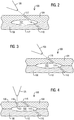
- a section, fragmentary view of a component 100 that may benefit from the disclosed method is shown in FIGs. 2-4 that collectively illustrate a flow sequence in connection with the disclosed method for constructing the impingement/effusion cooling features.
- the description below makes reference both to the flow chart and to the flow sequence and to facilitate the reader tracking the reference numerals in such figures, it is noted that the reference numerals in the flow chart start with the number 10 while the reference numbers in the flow sequence start with the number 100.
- step 14 allows arranging a pocket 102 between an outer wall 104 and an inner wall 106 of the component (for example walls 104,106 may respectively comprise the cold side and the hot side of the component).
- step 16 allows drilling with a lasing device 108 through the component to form an effusion hole 110 for the impingement/effusion cooling feature.
- Effusion hole 110 may be slanted relative to a surface 112 of the inner wall of the component and in flow communication with pocket 102 in the component via a pocket exit opening 114.
- pocket 102 and effusion hole 110, as illustrated in the drawings, should be construed in an example sense and not in a limiting sense since such configurations could be tailored based on the needs of a given application.
- pocket 102 could be construed as an elongated channel with one or more inlets (i.e., impingement holes) and one or more outlets (i.e., effusion holes). Accordingly, the number of holes and pocket configuration illustrated in the drawings should be construed in an example sense and not in a limiting sense.
- a thermal barrier coating may be optionally disposed on the surface of the inner wall prior to drilling step 16 with the lasing device through the component.
- drilling step 116 would allow drilling through the thermal barrier coating disposed on the surface of the inner wall of the component.
- the component may be optionally formed by an arrangement of diffusion bonded panels, and in this case drilling step 16 would allow drilling through the arrangement of diffusion bonded panels.
- the arrangement of diffusion bonded panels may comprise an intermediate panel disposed between an inner panel that constitutes the inner wall of the component and an outer panel that constitutes the outer wall of the component. Pocket 102 would be arranged in the intermediate panel, effusion hole 110 would be formed in the inner panel and impingement hole 118 would be formed in the outer panel.
- Step 18 allows closing (schematically represented by ellipse 116 in FIGs. 3-4 ) with lasing device 108 an opening 117 ( FIG. 2 ) formed at outer wall 104 of the component during the drilling with the lasing device through the component.
- closing step 18 may comprise welding opening 117 formed at the outer wall of the component during the drilling with the lasing device through the component.
- step 20 allows drilling with lasing device 108 through outer wall 104 of the component to form an impingement hole 118 ( FIG. 4 ) for the impingement/effusion cooling feature.
- Impingement hole 118 may be perpendicular relative to a surface 120 of outer wall 104 of the component and in flow communication with the pocket in the component via a pocket entry opening 122.
- FIG. 5 is a flow chart 50 of another disclosed method for constructing impingement/effusion cooling features in a component of a combustion turbine engine such as may comprise a multi-panel arrangement including a thermal barrier coating at a hot side of the component.
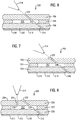
- a sectional fragmentary view of a component 200 that may benefit from the disclosed method is shown in FIGs. 6-8 that collectively illustrate a flow sequence in connection with the disclosed method for constructing the impingement/effusion cooling features.
- the description below makes reference both to the flow chart and to the flow sequence and to facilitate the reader tracking reference numerals in such figures, it is noted that the reference numerals in the flow chart start with the number 50 while the reference numbers in the flow sequence start with the number 200.
- step 54 allows arranging a pocket 202 disposed in an intermediate panel 204 as may be disposed between an outer panel 206 and an inner panel 208 of component 200 (for example panels 206, 208 may respectively comprise the cold side and the hot side of the component).
- step 56 allows disposing a thermal barrier coating 210 on a surface 212 of inner panel 208 of component 200.
- Step 58 allows drilling with a lasing device 214 through the component to form an effusion hole 216 for the impingement/effusion cooling feature.
- Effusion hole 216 may extend through inner panel 208 and thermal barrier coating 210.
- Effusion hole 216 may be slanted relative to a surface 218 of thermal barrier coating 210 and may be in flow communication with pocket 202 in the component via a pocket exit opening 220.
- an affixing of panels 204, 206, 208 may be performed prior to drilling step 58.
- the affixing of panels 204, 206, 208 to one another may comprise diffusion bonding of the panels. Since the disposing of thermal barrier coating on surface 212 of inner panel 208 is performed prior to drilling step 58, this avoids a masking of holes that otherwise would be present on surface 212 of inner panel 208.
- Step 60 allows closing (schematically represented by ellipse 222 in FIGs. 7-8 ) with the lasing device an opening 224 ( FIG. 6 ) formed at outer panel 206 of the component during the drilling with the lasing device through the component.
- closing step 60 comprises welding opening 224 formed at the outer wall of the component during the drilling with the lasing device through the component.
- step 62 Prior to return step 64, step 62 allows drilling with lasing device 214 through outer panel 206 of the component to form an impingement hole 226 ( FIG. 8 ) for the impingement/effusion cooling feature.
- Impingement hole 226 may be perpendicular relative to a surface 228 of outer panel 206 of the component and in flow communication with pocket 202 in the component via a pocket entry opening 230.
- the proposed methodology would allow performing an application of a thermal barrier coating without having to mask potentially thousands of pre-drilled holes disposed at the hot side of the component.
- Servicing operations can make use of the proposed methodology to strip and recoat a component without considering previous hole locations.
- bonding quality for joining such panels may be improved since such holes would not be present prior to the bonding and forming of the component.
- cooling air savings compared to a conventional cast design or a channel cooled bonded design, are estimated to improve by approximately 2-3% G1C depending on firing temperatures and coating characteristics. This is conducive to significant efficiency benefits for the engine.
Landscapes
- Engineering & Computer Science (AREA)
- Mechanical Engineering (AREA)
- General Engineering & Computer Science (AREA)
- Chemical & Material Sciences (AREA)
- Combustion & Propulsion (AREA)
- Turbine Rotor Nozzle Sealing (AREA)
Description
- Disclosed embodiments are generally related to combustion turbine engines, such as gas turbine engines and, more particularly, to method for constructing impingement/effusion cooling features in components of a combustion turbine engine.
- Typically, gas turbine engines include a compressor for compressing air, a combustor for mixing the compressed air with fuel and igniting the mixture, and a turbine section for producing power. Combustors often operate at substantially high temperatures. Accordingly, components, such as transition ducts and other components in the turbine engine should be appropriately cooled.
- See, for example, patent application
PCT/US2015/043966 , titled "Component Having Impingement Cooled Pockets Formed by Raised Ribs and a Cover Sheet Diffusion Bonded to the Raised Ribs"; and patent applicationPCT/US2016/043809 titled "Cooling Features for a Gas Turbine Engine", for non-limiting examples of impingement/effusion cooling features that may be used in components of a gas turbine engine. -
-
FIG. 1 is a flow chart of a disclosed method for constructing impingement/effusion cooling features in a component of a combustion turbine engine. -
FIGs. 2-4 show a flow sequence in connection with a component that may benefit from the disclosed method for constructing the impingement/effusion cooling features. -
FIG. 5 is a flow chart of a variant of the disclosed method for constructing impingement/effusion cooling features in a component of a combustion turbine engine, where, for example, the component may comprise a multi-panel arrangement. -
FIGs. 6-8 show a flow sequence in connection with a multi-panel arrangement that may benefit from the disclosed method for constructing the impingement/effusion cooling features. - The inventors of the present invention have recognized certain issues that can arise in the context of constructing impingement/effusion cooling features in components of a combustion turbine engine. The cooling features may involve impingement and effusion holes that without limitation may be constructed between two or more panels (e.g., a multi-panel arrangement) that may be bonded (e.g., diffusion bonding) or otherwise affixed to one another to form the body of the component, such as transition ducts, ring segments, combustor liners, etc. While bonded panel technology may be discussed herein, it should be understood that other techniques may be employed for affixing the panels, such as without limitation, casting, welding and brazing.
- In certain known techniques for constructing the impingement/effusion cooling features, the holes involved in the cooling features are generally drilled in individual panels prior to the bonding and forming of the component. That is, there may be drilling operations involved prior to the bonding and forming of the component. As a result of such drilling operations prior to the bonding and forming of the component, at least the following issues can arise. For example, hole geometry may distort from one panel to another panel during the hole-drilling operations. Similarly, hole positioning may shift from one panel to another panel during the hole-drilling operations.
- Another issue that can arise is that such holes may need to be masked during a coating operation, such as when applying a thermal barrier coating to a surface of the component that may be subject to a hot-flow of combustion gases. This masking operation can be substantially burdensome and costly, as the holes may not be straight through, and may not be readily masked. As will be appreciated by those skilled in the art, pin or polymer masking is generally substantially labor intensive. For example, in certain components there may be several thousand holes that may involve masking, and thus this masking can quickly become prohibitively costly. It will be appreciated that during servicing of a given component, stripping and recoating operations may be involved, and in this case, once again the holes would have to be masked during the recoating operation, which as noted above can be substantially burdensome and costly.
- In view of such a recognition, the present inventors propose an innovative methodology for constructing impingement/effusion cooling features in a component of a combustion turbine engine, where the proposed methodology in a cost-effective and reliable manner successfully overcomes the foregoing issues. In one non-limiting embodiment, the proposed methodology can make use of a single lasing device to construct highly efficient and low-flow impingement/effusion cooling features. The single lasing device may be configured by appropriately setting in a controller of the lasing device applicable lasing parameters for performing a desired laser operation, such as laser drilling and welding, to construct the impingement/effusion cooling features in components of the combustion turbine engine without having to perform drilling operations on the panels prior to affixing such panels to one another and thus overcoming the foregoing issues.
- In the following detailed description, various specific details are set forth in order to provide a thorough understanding of such embodiments. However, those skilled in the art will understand that embodiments of the present invention may be practiced without these specific details, that the present invention is not limited to the depicted embodiments, and that the present invention may be practiced in a variety of alternative embodiments. In other instances, methods, procedures, and components, which would be well-understood by one skilled in the art have not been described in detail to avoid unnecessary and burdensome explanation.
- Furthermore, various operations may be described as multiple discrete steps performed in a manner that is helpful for understanding embodiments of the present invention. However, the order of description should not be construed as to imply that these operations need be performed in the order they are presented, nor that they are even order dependent, unless otherwise indicated. Moreover, repeated usage of the phrase "in one embodiment" does not necessarily refer to the same embodiment, although it may. It is noted that disclosed embodiments need not be construed as mutually exclusive embodiments, since aspects of such disclosed embodiments may be appropriately combined by one skilled in the art depending on the needs of a given application.
- The terms "comprising", "including", "having", and the like, as used in the present application, are intended to be synonymous unless otherwise indicated. Lastly, as used herein, the phrases "configured to" or "arranged to" embrace the concept that the feature preceding the phrases "configured to" or "arranged to" is intentionally and specifically designed or made to act or function in a specific way and should not be construed to mean that the feature just has a capability or suitability to act or function in the specified way, unless so indicated.
-
FIG. 1 is aflow chart 10 of a disclosed method for constructing impingement/effusion cooling features in a component of a combustion turbine engine. A section, fragmentary view of acomponent 100 that may benefit from the disclosed method is shown inFIGs. 2-4 that collectively illustrate a flow sequence in connection with the disclosed method for constructing the impingement/effusion cooling features. The description below makes reference both to the flow chart and to the flow sequence and to facilitate the reader tracking the reference numerals in such figures, it is noted that the reference numerals in the flow chart start with thenumber 10 while the reference numbers in the flow sequence start with thenumber 100. - In one non-limiting embodiment, subsequent to a
start step 12,step 14 allows arranging apocket 102 between anouter wall 104 and aninner wall 106 of the component (for example walls 104,106 may respectively comprise the cold side and the hot side of the component).Step 16 allows drilling with alasing device 108 through the component to form aneffusion hole 110 for the impingement/effusion cooling feature.Effusion hole 110 may be slanted relative to asurface 112 of the inner wall of the component and in flow communication withpocket 102 in the component via apocket exit opening 114. It will be appreciated that the configuration ofpocket 102, andeffusion hole 110, as illustrated in the drawings, should be construed in an example sense and not in a limiting sense since such configurations could be tailored based on the needs of a given application. Without limitation,pocket 102 could be construed as an elongated channel with one or more inlets (i.e., impingement holes) and one or more outlets (i.e., effusion holes). Accordingly, the number of holes and pocket configuration illustrated in the drawings should be construed in an example sense and not in a limiting sense. - In one non-limiting embodiment, a thermal barrier coating may be optionally disposed on the surface of the inner wall prior to drilling
step 16 with the lasing device through the component. In this case,drilling step 116 would allow drilling through the thermal barrier coating disposed on the surface of the inner wall of the component. - In one non-limiting embodiment, the component may be optionally formed by an arrangement of diffusion bonded panels, and in this case drilling
step 16 would allow drilling through the arrangement of diffusion bonded panels. The arrangement of diffusion bonded panels may comprise an intermediate panel disposed between an inner panel that constitutes the inner wall of the component and an outer panel that constitutes the outer wall of the component. Pocket 102 would be arranged in the intermediate panel,effusion hole 110 would be formed in the inner panel andimpingement hole 118 would be formed in the outer panel. -
Step 18 allows closing (schematically represented byellipse 116 inFIGs. 3-4 ) withlasing device 108 an opening 117 (FIG. 2 ) formed atouter wall 104 of the component during the drilling with the lasing device through the component. In one non-limiting embodiment, closingstep 18 may comprise welding opening 117 formed at the outer wall of the component during the drilling with the lasing device through the component. - Prior to return
step 22,step 20 allows drilling withlasing device 108 throughouter wall 104 of the component to form an impingement hole 118 (FIG. 4 ) for the impingement/effusion cooling feature.Impingement hole 118 may be perpendicular relative to asurface 120 ofouter wall 104 of the component and in flow communication with the pocket in the component via apocket entry opening 122. -
FIG. 5 is aflow chart 50 of another disclosed method for constructing impingement/effusion cooling features in a component of a combustion turbine engine such as may comprise a multi-panel arrangement including a thermal barrier coating at a hot side of the component. A sectional fragmentary view of acomponent 200 that may benefit from the disclosed method is shown inFIGs. 6-8 that collectively illustrate a flow sequence in connection with the disclosed method for constructing the impingement/effusion cooling features. The description below makes reference both to the flow chart and to the flow sequence and to facilitate the reader tracking reference numerals in such figures, it is noted that the reference numerals in the flow chart start with thenumber 50 while the reference numbers in the flow sequence start with thenumber 200. - In one non-limiting embodiment, subsequent to a
start step 52,step 54 allows arranging apocket 202 disposed in anintermediate panel 204 as may be disposed between anouter panel 206 and aninner panel 208 of component 200 (forexample panels step 56 allows disposing athermal barrier coating 210 on asurface 212 ofinner panel 208 ofcomponent 200. -
Step 58 allows drilling with alasing device 214 through the component to form aneffusion hole 216 for the impingement/effusion cooling feature.Effusion hole 216 may extend throughinner panel 208 andthermal barrier coating 210.Effusion hole 216 may be slanted relative to asurface 218 ofthermal barrier coating 210 and may be in flow communication withpocket 202 in the component via apocket exit opening 220. In one non-limiting embodiment, an affixing ofpanels drilling step 58. - In one non-limiting embodiment, the affixing of
panels surface 212 ofinner panel 208 is performed prior todrilling step 58, this avoids a masking of holes that otherwise would be present onsurface 212 ofinner panel 208. -
Step 60 allows closing (schematically represented byellipse 222 inFIGs. 7-8 ) with the lasing device an opening 224 (FIG. 6 ) formed atouter panel 206 of the component during the drilling with the lasing device through the component. In one non-limiting embodiment, closingstep 60 compriseswelding opening 224 formed at the outer wall of the component during the drilling with the lasing device through the component. - Prior to return
step 64,step 62 allows drilling withlasing device 214 throughouter panel 206 of the component to form an impingement hole 226 (FIG. 8 ) for the impingement/effusion cooling feature.Impingement hole 226 may be perpendicular relative to asurface 228 ofouter panel 206 of the component and in flow communication withpocket 202 in the component via apocket entry opening 230. - In operation, the proposed methodology, for example, would allow performing an application of a thermal barrier coating without having to mask potentially thousands of pre-drilled holes disposed at the hot side of the component. Servicing operations can make use of the proposed methodology to strip and recoat a component without considering previous hole locations. Additionally, bonding quality for joining such panels may be improved since such holes would not be present prior to the bonding and forming of the component. Lastly, cooling air savings, compared to a conventional cast design or a channel cooled bonded design, are estimated to improve by approximately 2-3% G1C depending on firing temperatures and coating characteristics. This is conducive to significant efficiency benefits for the engine.
- While embodiments of the present disclosure have been disclosed in exemplary forms, it will be apparent to those skilled in the art that many modifications, additions, and deletions can be made therein without departing from the scope of the invention and its equivalents, as set forth in the following claims.
Claims (12)
- A method for constructing impingement/effusion cooling features in a component (100, 200) of a combustion turbine engine, the method comprising:arranging a pocket (102, 202) between an outer wall (104, 206) and an inner wall (106, 208) of the component (100, 200);drilling with a lasing device (108) through the component (100, 200) to form an effusion hole (110, 216) for the impingement/effusion cooling features, the effusion hole (110, 216) being slanted relative to a surface (112, 212) of the inner wall (106, 208) of the component (100, 200) and in flow communication with the pocket (102, 202) in the component (100, 200) via a pocket exit opening (114, 220);closing with the lasing device (108) an opening (117, 224) formed at the outer wall (104, 206) of the component (100, 200) during the drilling with the lasing device (108) through the component (100, 200); anddrilling with the lasing device (108) through the outer wall (104, 206) of the component (100, 200) to form an impingement hole (118, 226) in the impingement/effusion cooling arrangement, the impingement hole (118, 226) being perpendicular relative to a surface (120, 228) of the outer wall (104, 206) of the component (100, 200) and in flow communication with the pocket (102, 202) in the component (100, 200) via a pocket entry opening (122, 230).
- The method of claim 1,
further comprising disposing a thermal barrier coating on the surface (112) of the inner wall (106) prior to the drilling with the lasing device (108) through the component (100). - The method of claim 2,
wherein the drilling with the lasing device (108) through the component (100) to form the effusion hole (110) in the impingement/effusion cooling arrangement comprises drilling through the thermal barrier coating disposed on the surface (112) of the inner wall (106) of the component (100). - The method of claim 1,
wherein the component (200) is formed by an arrangement of panels affixed to one another. - The method of claim 4,
wherein the panels affixed to one another form an arrangement of diffusion bonded panels. - The method of claim 4 or 5,
wherein the drilling with the lasing device (108) through the component (200) to form the effusion hole (216) in the impingement/effusion cooling arrangement comprises drilling through the arrangement of panels. - The method of claim 6,
wherein the arrangement of panels comprises an intermediate panel (204) disposed between an inner panel (208) that constitutes the inner wall (106) of the component (100, 200) and an outer panel (206) that constitutes the outer wall (104) of the component (100, 200), wherein the pocket (202) is arranged in the intermediate panel (204), wherein the effusion hole (216) is formed in the inner panel (208) and the impingement hole (226) is formed in the outer panel (206). - The method of claim 7,
further comprising disposing a thermal barrier coating (210) on an inner panel surface (212) prior to the drilling with the lasing device (108) through the component (200). - The method of claim 8,
wherein the drilling with the lasing device (108) through the component (200) to form the effusion hole (216) in the impingement/effusion cooling arrangement comprises drilling through the arrangement of panels and the thermal barrier coating (210) disposed on the inner panel surface (212). - The method of one of the claims 1 to 9,
wherein the closing with the lasing device (108) comprises welding the opening (117, 224) formed at the outer wall (104, 206) of the component (100, 200) during the drilling with the lasing device (108) through the component (100, 200). - The method of one of the claims 3 or 9,
wherein the disposing of the thermal barrier coating (210) on the surface (112, 212) of the inner wall (106, 208) or the inner panel surface (212) is performed prior to the drilling with the lasing device (108) through the component (100, 200), thereby avoiding a masking of holes
that otherwise would be present on the surface (112, 212) of the inner wall (106, 208) or the inner panel surface (212) of the component (100, 200) when disposing the thermal barrier coating (210). - A transition duct of a combustion turbine engine comprising impingement/effusion cooling features constructed in said transition duct in
accordance with the method of any of the preceding claims.
Applications Claiming Priority (2)
| Application Number | Priority Date | Filing Date | Title |
|---|---|---|---|
| US201762526565P | 2017-06-29 | 2017-06-29 | |
| PCT/US2018/039911 WO2019006067A1 (en) | 2017-06-29 | 2018-06-28 | Method for constructing impingement/effusion cooling features in a component of a combustion turbine engine |
Publications (2)
| Publication Number | Publication Date |
|---|---|
| EP3645943A1 EP3645943A1 (en) | 2020-05-06 |
| EP3645943B1 true EP3645943B1 (en) | 2021-08-11 |
Family
ID=62976261
Family Applications (1)
| Application Number | Title | Priority Date | Filing Date |
|---|---|---|---|
| EP18743258.8A Active EP3645943B1 (en) | 2017-06-29 | 2018-06-28 | Method for constructing impingement/effusion cooling features in a component of a combustion turbine engine, and transition duct of a combustion turbine engine with impingement/effusion cooling features constructed according to said method |
Country Status (3)
| Country | Link |
|---|---|
| US (1) | US11092338B2 (en) |
| EP (1) | EP3645943B1 (en) |
| WO (1) | WO2019006067A1 (en) |
Family Cites Families (18)
| Publication number | Priority date | Publication date | Assignee | Title |
|---|---|---|---|---|
| US5498133A (en) * | 1995-06-06 | 1996-03-12 | General Electric Company | Pressure regulated film cooling |
| JP2003065068A (en) * | 2001-08-29 | 2003-03-05 | Mitsubishi Heavy Ind Ltd | Method for closing used hole on top of gas turbine blade |
| US20060016191A1 (en) * | 2004-07-23 | 2006-01-26 | Honeywell International Inc. | Combined effusion and thick TBC cooling method |
| US7219498B2 (en) * | 2004-09-10 | 2007-05-22 | Honeywell International, Inc. | Waffled impingement effusion method |
| US7625180B1 (en) * | 2006-11-16 | 2009-12-01 | Florida Turbine Technologies, Inc. | Turbine blade with near-wall multi-metering and diffusion cooling circuit |
| WO2010080502A2 (en) * | 2008-12-18 | 2010-07-15 | Nelson Stud Welding, Inc. | Turbine wheel and shaft joining processes |
| US20100272953A1 (en) * | 2009-04-28 | 2010-10-28 | Honeywell International Inc. | Cooled hybrid structure for gas turbine engine and method for the fabrication thereof |
| US8987629B2 (en) * | 2009-07-29 | 2015-03-24 | General Electric Company | Process of closing an opening in a component |
| US8647053B2 (en) * | 2010-08-09 | 2014-02-11 | Siemens Energy, Inc. | Cooling arrangement for a turbine component |
| US20120156020A1 (en) * | 2010-12-20 | 2012-06-21 | General Electric Company | Method of repairing a transition piece of a gas turbine engine |
| EP3055530B1 (en) * | 2013-10-07 | 2020-08-12 | United Technologies Corporation | Bonded combustor wall for a turbine engine |
| US9410702B2 (en) * | 2014-02-10 | 2016-08-09 | Honeywell International Inc. | Gas turbine engine combustors with effusion and impingement cooling and methods for manufacturing the same using additive manufacturing techniques |
| EP2995863B1 (en) | 2014-09-09 | 2018-05-23 | United Technologies Corporation | Single-walled combustor for a gas turbine engine and method of manufacture |
| US10731857B2 (en) * | 2014-09-09 | 2020-08-04 | Raytheon Technologies Corporation | Film cooling circuit for a combustor liner |
| US20160109130A1 (en) * | 2014-10-17 | 2016-04-21 | Pratt & Whitney Canada Corp. | Production of turbine components with heat-extracting features using additive manufacturing |
| EP3018415B1 (en) * | 2014-11-07 | 2020-01-01 | United Technologies Corporation | Combustor dilution hole cooling |
| CN109348723A (en) | 2015-08-06 | 2019-02-15 | 西门子公司 | Component with impingement cooling cavities formed by raised ribs and cover plates diffusion bonded to raised ribs |
| US10775044B2 (en) * | 2018-10-26 | 2020-09-15 | Honeywell International Inc. | Gas turbine engine dual-wall hot section structure |
-
2018
- 2018-06-28 US US16/609,336 patent/US11092338B2/en active Active
- 2018-06-28 EP EP18743258.8A patent/EP3645943B1/en active Active
- 2018-06-28 WO PCT/US2018/039911 patent/WO2019006067A1/en not_active Ceased
Also Published As
| Publication number | Publication date |
|---|---|
| EP3645943A1 (en) | 2020-05-06 |
| US20200063962A1 (en) | 2020-02-27 |
| WO2019006067A1 (en) | 2019-01-03 |
| US11092338B2 (en) | 2021-08-17 |
Similar Documents
| Publication | Publication Date | Title |
|---|---|---|
| EP2058475B1 (en) | Combustion liners for a combustion section of a gas turbine engine, corresponding combustion section, and gas turbine engine | |
| CN104061599B (en) | System for providing from fuel to burner | |
| EP2148139B1 (en) | Flow sleeve impingement cooling using a plenum ring | |
| US8186167B2 (en) | Combustor transition piece aft end cooling and related method | |
| EP2901081B1 (en) | Cooled combustor liner grommet | |
| US7805944B2 (en) | Combustion chamber air inlet | |
| EP3828468B1 (en) | System comprising a combustor and turbine inlet stator vanes | |
| US20110011563A1 (en) | Cooling method and apparatus | |
| EP3315866B1 (en) | Combustor assembly with mounted auxiliary component | |
| EP3066322B1 (en) | Coated cooling passage | |
| JP2009085222A (en) | Rear end liner assembly with turbulator and cooling method thereof | |
| US20220128007A1 (en) | Inleakage management apparatus | |
| EP3076078B1 (en) | Combustor configurations for a gas turbine engine | |
| EP3279568A1 (en) | Heat shield panel for gas turbine engine | |
| EP3026345B1 (en) | Nozzle guide with internal cooling for a gas turbine engine combustor | |
| US6865892B2 (en) | Combustion chamber/venturi configuration and assembly method | |
| EP3643968A1 (en) | Gas turbine engine dual-wall hot section structure | |
| EP1676993B1 (en) | Exhaust liner for gas turbine | |
| EP3236008B1 (en) | Systems and methods for producing one or more cooling holes in an airfoil for a gas turbine engine | |
| US11092338B2 (en) | Method for constructing impingement/effusion cooling features in a component of a combustion turbine engine | |
| JP2009103127A (en) | Cooling blade for turbomachine | |
| US7360364B2 (en) | Method and apparatus for assembling gas turbine engine combustors | |
| US10690345B2 (en) | Combustor assemblies for use in turbine engines and methods of assembling same | |
| US11320144B2 (en) | Combustion chamber assembly with different curvatures for a combustion chamber wall and a combustion chamber shingle fixed thereto | |
| EP3263840B1 (en) | Transition part assembly and combustor including the same |
Legal Events
| Date | Code | Title | Description |
|---|---|---|---|
| STAA | Information on the status of an ep patent application or granted ep patent |
Free format text: STATUS: UNKNOWN |
|
| STAA | Information on the status of an ep patent application or granted ep patent |
Free format text: STATUS: THE INTERNATIONAL PUBLICATION HAS BEEN MADE |
|
| PUAI | Public reference made under article 153(3) epc to a published international application that has entered the european phase |
Free format text: ORIGINAL CODE: 0009012 |
|
| STAA | Information on the status of an ep patent application or granted ep patent |
Free format text: STATUS: REQUEST FOR EXAMINATION WAS MADE |
|
| 17P | Request for examination filed |
Effective date: 20191227 |
|
| AK | Designated contracting states |
Kind code of ref document: A1 Designated state(s): AL AT BE BG CH CY CZ DE DK EE ES FI FR GB GR HR HU IE IS IT LI LT LU LV MC MK MT NL NO PL PT RO RS SE SI SK SM TR |
|
| AX | Request for extension of the european patent |
Extension state: BA ME |
|
| DAV | Request for validation of the european patent (deleted) | ||
| DAX | Request for extension of the european patent (deleted) | ||
| RAP1 | Party data changed (applicant data changed or rights of an application transferred) |
Owner name: SIEMENS ENERGY GLOBAL GMBH & CO. KG |
|
| GRAP | Despatch of communication of intention to grant a patent |
Free format text: ORIGINAL CODE: EPIDOSNIGR1 |
|
| STAA | Information on the status of an ep patent application or granted ep patent |
Free format text: STATUS: GRANT OF PATENT IS INTENDED |
|
| INTG | Intention to grant announced |
Effective date: 20210407 |
|
| GRAS | Grant fee paid |
Free format text: ORIGINAL CODE: EPIDOSNIGR3 |
|
| GRAA | (expected) grant |
Free format text: ORIGINAL CODE: 0009210 |
|
| STAA | Information on the status of an ep patent application or granted ep patent |
Free format text: STATUS: THE PATENT HAS BEEN GRANTED |
|
| AK | Designated contracting states |
Kind code of ref document: B1 Designated state(s): AL AT BE BG CH CY CZ DE DK EE ES FI FR GB GR HR HU IE IS IT LI LT LU LV MC MK MT NL NO PL PT RO RS SE SI SK SM TR |
|
| REG | Reference to a national code |
Ref country code: CH Ref legal event code: EP |
|
| REG | Reference to a national code |
Ref country code: DE Ref legal event code: R096 Ref document number: 602018021714 Country of ref document: DE |
|
| REG | Reference to a national code |
Ref country code: IE Ref legal event code: FG4D Ref country code: AT Ref legal event code: REF Ref document number: 1419754 Country of ref document: AT Kind code of ref document: T Effective date: 20210915 |
|
| REG | Reference to a national code |
Ref country code: LT Ref legal event code: MG9D |
|
| REG | Reference to a national code |
Ref country code: NL Ref legal event code: MP Effective date: 20210811 |
|
| REG | Reference to a national code |
Ref country code: AT Ref legal event code: MK05 Ref document number: 1419754 Country of ref document: AT Kind code of ref document: T Effective date: 20210811 |
|
| PG25 | Lapsed in a contracting state [announced via postgrant information from national office to epo] |
Ref country code: FI Free format text: LAPSE BECAUSE OF FAILURE TO SUBMIT A TRANSLATION OF THE DESCRIPTION OR TO PAY THE FEE WITHIN THE PRESCRIBED TIME-LIMIT Effective date: 20210811 Ref country code: ES Free format text: LAPSE BECAUSE OF FAILURE TO SUBMIT A TRANSLATION OF THE DESCRIPTION OR TO PAY THE FEE WITHIN THE PRESCRIBED TIME-LIMIT Effective date: 20210811 Ref country code: HR Free format text: LAPSE BECAUSE OF FAILURE TO SUBMIT A TRANSLATION OF THE DESCRIPTION OR TO PAY THE FEE WITHIN THE PRESCRIBED TIME-LIMIT Effective date: 20210811 Ref country code: RS Free format text: LAPSE BECAUSE OF FAILURE TO SUBMIT A TRANSLATION OF THE DESCRIPTION OR TO PAY THE FEE WITHIN THE PRESCRIBED TIME-LIMIT Effective date: 20210811 Ref country code: SE Free format text: LAPSE BECAUSE OF FAILURE TO SUBMIT A TRANSLATION OF THE DESCRIPTION OR TO PAY THE FEE WITHIN THE PRESCRIBED TIME-LIMIT Effective date: 20210811 Ref country code: BG Free format text: LAPSE BECAUSE OF FAILURE TO SUBMIT A TRANSLATION OF THE DESCRIPTION OR TO PAY THE FEE WITHIN THE PRESCRIBED TIME-LIMIT Effective date: 20211111 Ref country code: AT Free format text: LAPSE BECAUSE OF FAILURE TO SUBMIT A TRANSLATION OF THE DESCRIPTION OR TO PAY THE FEE WITHIN THE PRESCRIBED TIME-LIMIT Effective date: 20210811 Ref country code: LT Free format text: LAPSE BECAUSE OF FAILURE TO SUBMIT A TRANSLATION OF THE DESCRIPTION OR TO PAY THE FEE WITHIN THE PRESCRIBED TIME-LIMIT Effective date: 20210811 Ref country code: NO Free format text: LAPSE BECAUSE OF FAILURE TO SUBMIT A TRANSLATION OF THE DESCRIPTION OR TO PAY THE FEE WITHIN THE PRESCRIBED TIME-LIMIT Effective date: 20211111 Ref country code: PT Free format text: LAPSE BECAUSE OF FAILURE TO SUBMIT A TRANSLATION OF THE DESCRIPTION OR TO PAY THE FEE WITHIN THE PRESCRIBED TIME-LIMIT Effective date: 20211213 |
|
| PG25 | Lapsed in a contracting state [announced via postgrant information from national office to epo] |
Ref country code: PL Free format text: LAPSE BECAUSE OF FAILURE TO SUBMIT A TRANSLATION OF THE DESCRIPTION OR TO PAY THE FEE WITHIN THE PRESCRIBED TIME-LIMIT Effective date: 20210811 Ref country code: LV Free format text: LAPSE BECAUSE OF FAILURE TO SUBMIT A TRANSLATION OF THE DESCRIPTION OR TO PAY THE FEE WITHIN THE PRESCRIBED TIME-LIMIT Effective date: 20210811 Ref country code: GR Free format text: LAPSE BECAUSE OF FAILURE TO SUBMIT A TRANSLATION OF THE DESCRIPTION OR TO PAY THE FEE WITHIN THE PRESCRIBED TIME-LIMIT Effective date: 20211112 |
|
| PG25 | Lapsed in a contracting state [announced via postgrant information from national office to epo] |
Ref country code: NL Free format text: LAPSE BECAUSE OF FAILURE TO SUBMIT A TRANSLATION OF THE DESCRIPTION OR TO PAY THE FEE WITHIN THE PRESCRIBED TIME-LIMIT Effective date: 20210811 |
|
| PG25 | Lapsed in a contracting state [announced via postgrant information from national office to epo] |
Ref country code: DK Free format text: LAPSE BECAUSE OF FAILURE TO SUBMIT A TRANSLATION OF THE DESCRIPTION OR TO PAY THE FEE WITHIN THE PRESCRIBED TIME-LIMIT Effective date: 20210811 |
|
| REG | Reference to a national code |
Ref country code: DE Ref legal event code: R097 Ref document number: 602018021714 Country of ref document: DE |
|
| PG25 | Lapsed in a contracting state [announced via postgrant information from national office to epo] |
Ref country code: SM Free format text: LAPSE BECAUSE OF FAILURE TO SUBMIT A TRANSLATION OF THE DESCRIPTION OR TO PAY THE FEE WITHIN THE PRESCRIBED TIME-LIMIT Effective date: 20210811 Ref country code: SK Free format text: LAPSE BECAUSE OF FAILURE TO SUBMIT A TRANSLATION OF THE DESCRIPTION OR TO PAY THE FEE WITHIN THE PRESCRIBED TIME-LIMIT Effective date: 20210811 Ref country code: RO Free format text: LAPSE BECAUSE OF FAILURE TO SUBMIT A TRANSLATION OF THE DESCRIPTION OR TO PAY THE FEE WITHIN THE PRESCRIBED TIME-LIMIT Effective date: 20210811 Ref country code: EE Free format text: LAPSE BECAUSE OF FAILURE TO SUBMIT A TRANSLATION OF THE DESCRIPTION OR TO PAY THE FEE WITHIN THE PRESCRIBED TIME-LIMIT Effective date: 20210811 Ref country code: CZ Free format text: LAPSE BECAUSE OF FAILURE TO SUBMIT A TRANSLATION OF THE DESCRIPTION OR TO PAY THE FEE WITHIN THE PRESCRIBED TIME-LIMIT Effective date: 20210811 Ref country code: AL Free format text: LAPSE BECAUSE OF FAILURE TO SUBMIT A TRANSLATION OF THE DESCRIPTION OR TO PAY THE FEE WITHIN THE PRESCRIBED TIME-LIMIT Effective date: 20210811 |
|
| PLBE | No opposition filed within time limit |
Free format text: ORIGINAL CODE: 0009261 |
|
| STAA | Information on the status of an ep patent application or granted ep patent |
Free format text: STATUS: NO OPPOSITION FILED WITHIN TIME LIMIT |
|
| 26N | No opposition filed |
Effective date: 20220512 |
|
| PG25 | Lapsed in a contracting state [announced via postgrant information from national office to epo] |
Ref country code: SI Free format text: LAPSE BECAUSE OF FAILURE TO SUBMIT A TRANSLATION OF THE DESCRIPTION OR TO PAY THE FEE WITHIN THE PRESCRIBED TIME-LIMIT Effective date: 20210811 |
|
| PG25 | Lapsed in a contracting state [announced via postgrant information from national office to epo] |
Ref country code: MC Free format text: LAPSE BECAUSE OF FAILURE TO SUBMIT A TRANSLATION OF THE DESCRIPTION OR TO PAY THE FEE WITHIN THE PRESCRIBED TIME-LIMIT Effective date: 20210811 |
|
| REG | Reference to a national code |
Ref country code: BE Ref legal event code: MM Effective date: 20220630 |
|
| PG25 | Lapsed in a contracting state [announced via postgrant information from national office to epo] |
Ref country code: LU Free format text: LAPSE BECAUSE OF NON-PAYMENT OF DUE FEES Effective date: 20220628 Ref country code: IE Free format text: LAPSE BECAUSE OF NON-PAYMENT OF DUE FEES Effective date: 20220628 |
|
| PG25 | Lapsed in a contracting state [announced via postgrant information from national office to epo] |
Ref country code: BE Free format text: LAPSE BECAUSE OF NON-PAYMENT OF DUE FEES Effective date: 20220630 |
|
| PG25 | Lapsed in a contracting state [announced via postgrant information from national office to epo] |
Ref country code: MK Free format text: LAPSE BECAUSE OF FAILURE TO SUBMIT A TRANSLATION OF THE DESCRIPTION OR TO PAY THE FEE WITHIN THE PRESCRIBED TIME-LIMIT Effective date: 20210811 Ref country code: CY Free format text: LAPSE BECAUSE OF FAILURE TO SUBMIT A TRANSLATION OF THE DESCRIPTION OR TO PAY THE FEE WITHIN THE PRESCRIBED TIME-LIMIT Effective date: 20210811 |
|
| PG25 | Lapsed in a contracting state [announced via postgrant information from national office to epo] |
Ref country code: HU Free format text: LAPSE BECAUSE OF FAILURE TO SUBMIT A TRANSLATION OF THE DESCRIPTION OR TO PAY THE FEE WITHIN THE PRESCRIBED TIME-LIMIT; INVALID AB INITIO Effective date: 20180628 |
|
| PG25 | Lapsed in a contracting state [announced via postgrant information from national office to epo] |
Ref country code: MT Free format text: LAPSE BECAUSE OF FAILURE TO SUBMIT A TRANSLATION OF THE DESCRIPTION OR TO PAY THE FEE WITHIN THE PRESCRIBED TIME-LIMIT Effective date: 20210811 |
|
| PGFP | Annual fee paid to national office [announced via postgrant information from national office to epo] |
Ref country code: DE Payment date: 20250626 Year of fee payment: 8 |
|
| PGFP | Annual fee paid to national office [announced via postgrant information from national office to epo] |
Ref country code: GB Payment date: 20250617 Year of fee payment: 8 |
|
| PGFP | Annual fee paid to national office [announced via postgrant information from national office to epo] |
Ref country code: FR Payment date: 20250624 Year of fee payment: 8 |
|
| PGFP | Annual fee paid to national office [announced via postgrant information from national office to epo] |
Ref country code: IT Payment date: 20250623 Year of fee payment: 8 |
|
| PGFP | Annual fee paid to national office [announced via postgrant information from national office to epo] |
Ref country code: CH Payment date: 20250701 Year of fee payment: 8 |
|
| PG25 | Lapsed in a contracting state [announced via postgrant information from national office to epo] |
Ref country code: TR Free format text: LAPSE BECAUSE OF FAILURE TO SUBMIT A TRANSLATION OF THE DESCRIPTION OR TO PAY THE FEE WITHIN THE PRESCRIBED TIME-LIMIT Effective date: 20210811 |