EP3645769B1 - Method of making an article - Google Patents
Method of making an article Download PDFInfo
- Publication number
- EP3645769B1 EP3645769B1 EP18755304.5A EP18755304A EP3645769B1 EP 3645769 B1 EP3645769 B1 EP 3645769B1 EP 18755304 A EP18755304 A EP 18755304A EP 3645769 B1 EP3645769 B1 EP 3645769B1
- Authority
- EP
- European Patent Office
- Prior art keywords
- film
- thermally
- cex
- graphite
- softenable
- Prior art date
- Legal status (The legal status is an assumption and is not a legal conclusion. Google has not performed a legal analysis and makes no representation as to the accuracy of the status listed.)
- Active
Links
Images
Classifications
-
- C—CHEMISTRY; METALLURGY
- C23—COATING METALLIC MATERIAL; COATING MATERIAL WITH METALLIC MATERIAL; CHEMICAL SURFACE TREATMENT; DIFFUSION TREATMENT OF METALLIC MATERIAL; COATING BY VACUUM EVAPORATION, BY SPUTTERING, BY ION IMPLANTATION OR BY CHEMICAL VAPOUR DEPOSITION, IN GENERAL; INHIBITING CORROSION OF METALLIC MATERIAL OR INCRUSTATION IN GENERAL
- C23C—COATING METALLIC MATERIAL; COATING MATERIAL WITH METALLIC MATERIAL; SURFACE TREATMENT OF METALLIC MATERIAL BY DIFFUSION INTO THE SURFACE, BY CHEMICAL CONVERSION OR SUBSTITUTION; COATING BY VACUUM EVAPORATION, BY SPUTTERING, BY ION IMPLANTATION OR BY CHEMICAL VAPOUR DEPOSITION, IN GENERAL
- C23C24/00—Coating starting from inorganic powder
- C23C24/02—Coating starting from inorganic powder by application of pressure only
-
- C—CHEMISTRY; METALLURGY
- C23—COATING METALLIC MATERIAL; COATING MATERIAL WITH METALLIC MATERIAL; CHEMICAL SURFACE TREATMENT; DIFFUSION TREATMENT OF METALLIC MATERIAL; COATING BY VACUUM EVAPORATION, BY SPUTTERING, BY ION IMPLANTATION OR BY CHEMICAL VAPOUR DEPOSITION, IN GENERAL; INHIBITING CORROSION OF METALLIC MATERIAL OR INCRUSTATION IN GENERAL
- C23C—COATING METALLIC MATERIAL; COATING MATERIAL WITH METALLIC MATERIAL; SURFACE TREATMENT OF METALLIC MATERIAL BY DIFFUSION INTO THE SURFACE, BY CHEMICAL CONVERSION OR SUBSTITUTION; COATING BY VACUUM EVAPORATION, BY SPUTTERING, BY ION IMPLANTATION OR BY CHEMICAL VAPOUR DEPOSITION, IN GENERAL
- C23C24/00—Coating starting from inorganic powder
- C23C24/02—Coating starting from inorganic powder by application of pressure only
- C23C24/04—Impact or kinetic deposition of particles
Definitions
- the present disclosure broadly relates to methods for improving the durability of particle coatings on thermally-softenable films, and articles preparable thereby.
- Coatings of certain particles (e.g., graphite) on substrates can be formed by rubbing a powder containing the particles against a substrate such as, for example, a thermoplastic film.
- a powder coating will be referred to herein as "powder-rubbed coatings".
- powder-rubbed coatings examples include those disclosed in U. S. Pat. No. 6,511,701 B1 (Divigalpitiya et al. ).
- powder-rubbed coatings and methods of forming them include those disclosed in U. S. Pat. No. 6,511,701 B1 (Divigalpitiya et al. ).
- such films are typically prone to damage by methods such as abrasion and/or rinsing with solvent.
- US Patent 6511701B1 discloses a method of coating a polymer substrate with a dry composition comprising particles.
- the particles have a Mohs hardness between 1 and 2.5 and preferably a largest dimension of less than 100 microns.
- the particles are buffed on the substrate with an applicator which moves in a manner parallel to the surface of the substrate.
- US patent US4741918 discloses a abstract coated with a coating material by rubbing substantially dry discrete particles of the coating material across the surface of the substrate with a sufficient rate of energy input to cause them to adhere. The particles are carried on the surface of a soft, resilient buffing wheel rotating sufficient rapidly to give peripheral speeds of from 2 to 200 m/s.
- Exemplified coating materials include metals, metal oxides and plastics.
- US patent application US2014329082 discloses an article including a substrate having a first major surface and optionally a second major surface. A layering arrangement is disposed on either or both of the first major surface and the second major surface. The layering arrangement includes a carbon layer and a conducting polymer layer.
- US patent US5925402 discloses coating powder is applied to a substrate as a means of providing a patterned coating on a substrate, either decorative or functional. Then the coating powder is fused or fused and cured in selected portions by computer-guided laser.
- US patent application US2015344712 discloses methods and compositions for creating durable surface marks and/or decorations on substrates including metal, glass, ceramic, porcelain, natural and engineered stone, as well as plastics, polymer composites and other organic materials with color, high resolution and high contrast using inkjet technology and laser, NIR diode or UV LED energy. Smoothness and durability are obtained by using nanoparticles of silica, pigments and other materials in such marking processes.
- the present disclosure provides a method of making an article comprising exposing a particle coating disposed on a thermally-softenable film to a modulated source of electromagnetic radiation wherein the thermally-softenable film comprises a thermoplastic polymer, wherein the modulated source of electromagnetic radiation comprises a flashlamp, wherein the particle coating consists essentially of graphite, wherein the particle coating comprises loosely bound distinct particles that are not covalently bonded to each other, and are not retained in a binder material other than the thermally-softenable film.
- An article prepared according to the above method comprises a thermally-softenable film having a particle coating disposed thereon, wherein the particle coating comprises distinct particles that are not covalently bonded to each other, and are not retained in a binder material other than the thermally-softenable film, and wherein at least one portion of the particle coating corresponding to a predetermined pattern has a greater transmittance to visible light than at least one portion of the particle coating that is not disposed within the predetermined pattern.
- An article prepared according to the above method comprises a thermally-softenable film having a particle coating disposed thereon, wherein the particle coating comprises distinct particles that are not chemically bonded to each other and are not retained in a binder material other than the thermally-softenable film, and wherein the change in transmittance is at most 60 percent after abrading the particle coating according to ASTM D6279-15 "Standard Test Method for Rub Abrasion Mar Resistance of High Gloss Coatings" with the 25 mm friction element being outfitted with a two inch square Crockmeter cloth soaked in isopropanol for three seconds.
- powder refers to a free-flowing collection of minute particles.
- pulsed electromagnetic radiation refers to electromagnetic radiation that is modulated to become a series of discrete spikes with increased intensity.
- the spikes may be relative to a background level of electromagnetic radiation that is negligible or zero, or the background level may be at a higher level that is substantially ineffective to increase adhesion of particles in the particle coating to the film.
- thermo-softenable means softenable upon heating.
- particle coating refers to a coating of minute particles which may or may not be free-flowing.
- the present disclosure provides an easy method to enhance the durability of particle coatings (e.g., to solvent abrading) on thermally-softenable films using instantaneous heating by exposure to a modulated source of electromagnetic radiation comprising a flashlamp.
- exemplary article 100 comprises a thermally-softenable (e.g., thermoplastic) film 110 having a particle coating 120 disposed thereon.
- the particle coating comprises distinct particles that are not covalently bonded to each other and are not retained in a binder material other than the thermally-softenable film.
- Particle coatings on thermally-softenable films can be prepared by various known methods including, for example, exposure to an aerosolized powder cloud, contact with a powder bed, coating with a solvent-based powder dispersion coating followed by evaporation of solvent, and/or triboadhesion (rubbing dry particles against a substrate to form a powder-rubbed coating) of the powder using a rubbing process.
- triboadhesion methods can be found in U. S. Pat. Nos. 6,511,701 B1 (Divigalpitiya et al. ), 6,025,014 (Stango ), and 4,741,918 (Nagybaczon et al. ). The remaining methods will be familiar to those of ordinary skill in the art.
- Useful powders comprise minute loosely bound particles capable of absorbing at least one wavelength of the pulsed electromagnetic radiation, preferably corresponding to a majority of the energy of the pulsed electromagnetic radiation.
- Suitable powders are preferably at least substantially unaffected by electromagnetic radiation, but are moderate to strong absorbers of it. This is desirable to maximize the light (electromagnetic radiation) to heat conversion yield without altering the chemical nature of the powder particles.
- Powders include powders comprising graphite, clays, hexagonal boron nitride, pigments, inorganic oxides (e.g., alumina, calcia, silica, ceria, zinc oxide, or titania), metal(s), organic polymeric particles (e.g., polytetrafluoroethylene, polyvinylidene difluoride), carbides (e.g., silicon carbide), flame retardants (e.g., aluminum trihydrate, aluminum hydroxide, magnesium hydroxide, sodium hexametaphosphate, organic phosphonates and phosphates and ester thereof), carbonates (e.g., calcium carbonate, magnesium carbonate, sodium carbonate), dry biological powders (e.g., spores, bacteria), and combinations thereof.
- inorganic oxides e.g., alumina, calcia, silica, ceria, zinc oxide, or titania
- metal(s) e.g., aluminum boronitride,
- the powder particles have an average particle size of 0.1 to 100 micrometers, more preferably 1 to 50 micrometers, and more preferably 1 to 25 micrometers, although this is not a requirement.
- the particle coating according to the invention consists essentially of graphite.
- the particle coating after application, consists essentially of (i.e., be at least 98 percent by weight, preferably at least 99 percent by weight, or even consist of) graphite particles.
- the particle coating Prior to exposure to the electromagnetic radiation the particle coating comprises loosely bound distinct particles that are not covalently bonded to each other, and are not retained in a binder material other than the thermally-softenable film itself.
- the thermally-softenable film comprises one or more thermally-softenable (e.g., lightly crosslinked and/or thermoplastic) polymers.
- thermally-softenable polymers that may be suitable for inclusion in a thermally-softenable film include polycarbonates, polyesters, polyamides, polyimides, polyurethanes, polyetherketone (PEK), polyetheretherketone (PEEK), polyphenylene sulfide, polyacrylics (e.g., polymethyl methacrylate), polyolefins (e.g., polyethylene, polypropylene, biaxially-oriented polypropylene), and combinations of such resins.
- a pulsed electromagnetic radiation may come from any source(s) capable of generating sufficient fluence and pulse duration to effect sufficient heating of the thermally-softenable film to cause the particle coating to bind more tightly to it.
- sources may be effective for this purpose: flashlamps, lasers, and shuttered lamps.
- flashlamps lasers
- shuttered lamps The selection of appropriate sources will typically be influenced by desired process conditions such as, for example, line speed, line width, spectral output, and cost.
- the pulsed electromagnetic radiation is generated using a flashlamp.
- xenon and krypton flashlamps are the most common. Both provide a broad continuous output over the wavelength range 200 to 1000 nanometers, however the krypton flashlamps have higher relative output intensity in the 750-900 nm wavelength range as compared to xenon flashlamps which have more relative output in the 300 to 750 nm wavelength range.
- xenon flashlamps are preferred for most applications, and especially those involving graphite powder.
- Many suitable xenon and krypton flashlamps are commercially available from vendors such as Excelitas Technologies Corp. of Waltham, Massachusetts and Heraeus of Hanau, Germany.
- a pulsed electromagnetic radiation can be generated using a pulsed laser.
- Suitable lasers may include, for example, excimer lasers (e.g., XeF (351 nm), XeCl (308 nm), and KrF (248 nm)), solid state lasers (e.g., ruby 694 nm)), and nitrogen lasers (337.1 nm).
- a pulsed electromagnetic radiation is generated using a continuous light source and a shutter (preferably a rotating aperture/shutter to reduce overheating of the shutter).
- Suitable light sources may include high-pressure mercury lamps, xenon lamps, and metal-halide lamps.
- the electromagnetic radiation spectrum is preferably most intense at wavelength(s) that are strongly absorbed by the powder particles, although this is not a requirement.
- the electromagnetic radiation spectrum is preferably most intense in spectral regions in which the powder is least reflective, although this is not a requirement.
- the source of pulsed electromagnetic radiation is capable of generating a high fluence (energy density) with high intensity (high power per unit area), although this is not a requirement.
- high fluence energy density
- intensity high power per unit area
- the pulse duration is preferably short; e.g., less than 10 milliseconds, less than 1 millisecond, less than 100 microseconds, less than 10 microseconds, or even less than 1 microsecond, although this is not a requirement.
- the pulsed electromagnetic radiation preferably be powerful, but the exposure area is preferably large and the pulse repetition rate is preferably fast (e.g., 100 to 500 Hz).
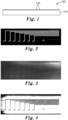
- the modulated electromagnetic radiation may be directed through a mask having transmissive and non-transmissive regions according to a predetermined pattern (e.g., see Fig 2 .). Accordingly, exposed regions of the particle coating may become more transparent to visible light than unexposed region of the particle coating (see Fig. 3 ).
- an optional development step e.g., mild abrasion with a solvent-soaked wiper
- a particle coating remains in the exposed region according to the predetermined pattern while it is substantially or completely removed in the unexposed (i.e., blocked) region (see FIG. 4 ).
- the present disclosure provides a method comprising exposing a particle coating disposed on a thermally-softenable film to a modulated source of electromagnetic radiation, wherein the thermally-softenable film comprises a thermoplastic polymer, wherein the modulated source of electromagnetic radiation comprises a flashlamp, wherein the particle coating consists essentially of graphite, wherein the particle coating comprises loosely bound distinct particles that are not covalently bonded to each other, and are not retained in a binder material other than the thermally-softenable film.
- the present disclosure provides a method according to the first wherein the particle coating comprises a powder-rubbed coating.
- the present disclosure provides a method according to any one of the first to second embodiments, wherein the particle coating is exposed to the pulsed electromagnetic radiation according to a predetermined pattern.
- PET polyethylene terephthalate (PET) film 125 micrometers thick, glass transition temperature (T g ) of 76°C, obtained from DuPont Tejin Films, Chester Virginia, as MELINEX ST505 polyester film
- T g glass transition temperature
- MELINEX ST505 polyester film Bare PET PET film, 2-mil, (51 micrometers) thickness
- MICRO 850 Graphite powder 3-5 micrometers particle size, 13 m 2 /g surface area, 0.088 ohm ⁇ cm resistivity, obtained from Ashbury Graphite Mills, Inc., Kittanning, Pennsylvania as MICRO850 graphite Isopropanol (IPA) solvent, obtained from Aldrich Chemical Company, Milwaukee, Wisconsin
- graphite coatings were applied onto PET films by placing a small amount of MICRO850 on the PET films. The graphite was then rubbed against the film using a WEN 10PMC 10-inch (25.8-cm) random orbital waxer/polisher (WEN Products, Elgin, Illinois) equipped with a wool polishing bonnet. The relative amount of graphite coating deposited on the PET film was determined by measuring the surface resistivity using a four-point probe and/or light transmittance.
- CEX-C and EX10 to EX12 were evaluated for durability according to ASTM D6279-15 "Standard Test Method for Rub Abrasion Mar Resistance of High Gloss Coatings", ASTM International, West Conshocken, Pennsylvania, with the 25 mm friction element being outfitted with a two inch (5.1 cm) square Crockmeter cloth soaked in isopropanol for three seconds.
- Crockmeter cloth is available from Testfabrics, Inc. West Pittson, Pennsylvania.
- Crockmeter cloth conforms to the specifications of ASTM D3690-02(2009) "Standard Performance Specification for Vinyl-Coated and Urethane-Coated Upholstery Fabrics-Indoor".
- Transmittance of graphite-coated film specimens was measured before and after durability testing. All transmittance measurements represent an average of at least 3 measurements.
- T film is the transmittance of the underlying polymer film
- T C is the transmittance of that same film after the coating and treatments had been applied
- T abraded is the transmittance of the coating after being subjected to the desired number of abrading cycles.
- Transmittance values of the films are typically around 92 ⁇ 5%, depending on the quality of the substrate used. Smaller changes in transmittance ( ⁇ T, %) are indicative of higher retention of the total fraction of carbon on the original film.
- CEX-A to CEX-C and EX-1 to EX-12 were prepared by subjecting graphite coated PET substrate films prepared as described above to an Intense Pulsed Light (IPL) irradiation.
- IPL Intense Pulsed Light
- the source used was a SINTERON S-2100 Xe flashlamp equipped with Type C bulb from Xenon Corporation, Wilmington, Massachusetts.
- the substrate was Bare PET.
- EX-1 was placed under the flashlamp with the graphite-coated surface facing up and treated ten times at a pulse rate of 1 Hz and an energy density of 0.4 J/cm 2 .
- CEX-B was prepared in the same manner as CEX-A, except that the substrate was Melinex PET.
- EX-2 was prepared in the same manner as EX-1, except that the substrate was Melinex PET and treated 5 times at a pulse rate of 1 Hz and an energy density of 0.3 J/cm 2 .
- EX-3 and EX-4 were prepared in the same manner as EX-2, except that the film was treated 1 time at a pulse rate of 1 Hz and an energy density of 0.5 J/cm 2 (EX-3) and 1.0 J/cm 2 (EX-4).
- EX-5 was prepared similarly to EX-4, except the film was flipped over such that the graphite coated surface was facing away from the flashlamp bulb.
- EX-6 to EX-8 were prepared by coating three separate sheets of Bare PET with differing amounts of graphite to achieve differing surface resistivity values for each Example. EX-6 to EX-8 were placed under the flashlamp with the graphite-coated surface facing up and treated ten times at a pulse rate of 1 Hz and an energy density of 0.4 J/cm 2 . Table 2, below, reports the change in transmittance ⁇ T in %. TABLE 2 EXAMPLE INITIAL SURFACE RESISTIVITY, ⁇ /square ⁇ T, % EX-6 250 14.5 EX-7 564 22.3 EX-8 975 23.4
- the substrate coated with graphite was Bare PET.
- a chromium/glass patterned photomask shown in Fig. 2
- the area directly adjacent to the mask is denoted as the unmasked area, whereas the area beneath the mask was shielded from IPL and is denoted as the masked area.
- the photomask included linear shape openings in the chrome layer having width of approximately about 250 micrometers or having width of approximately about 500 micrometers. This demonstrates the ability of these coatings to be patterned, with the openings portion of the mask representing a desired pattern for improved particle retention.
- Table 3 report the effects of IPL on particle retention of masked and unmasked (patterned) graphite coated PET.
- Fig. 3 shows the resulting pattern, with the portion beneath the openings and masked portion.
- Fig. 4 shows the resulting pattern after being subjected to abrasion as described above, with the portion beneath the openings remaining coated with carbon and the masked portion being devoid of carbon due to abrasion.
- the substrate was Bare PET.
- EX-10 was placed under the flashlamp with the graphite-coated surface facing up and treated ten times at a pulse rate of 1 Hz and an energy density of 0.4 J/cm 2 .
- EX-11 was prepared in the same manner as EX-10, except that the film was coated with a different amount of graphite to achieve a higher surface resistivity value than EX-10.
- EX-12 was prepared in the same manner EX-10, except that the substrate was Melinex PET and treated 5 times at a pulse rate of 1 Hz and an energy density of 0.3 J/cm 2 .
- Tables 5-7 summarize the effect of heat gun (Table 5), e-beam (Table 6), and biaxial stretch (Table 7) exposures had on particle retention ( ⁇ T, %, average normalized change in transmission).
- ⁇ T particle retention
- % average normalized change in transmission
Landscapes
- Chemical & Material Sciences (AREA)
- Chemical Kinetics & Catalysis (AREA)
- Engineering & Computer Science (AREA)
- Materials Engineering (AREA)
- Mechanical Engineering (AREA)
- Metallurgy (AREA)
- Organic Chemistry (AREA)
- Laminated Bodies (AREA)
- Paints Or Removers (AREA)
- Coating Of Shaped Articles Made Of Macromolecular Substances (AREA)
- Application Of Or Painting With Fluid Materials (AREA)
Description
- The present disclosure broadly relates to methods for improving the durability of particle coatings on thermally-softenable films, and articles preparable thereby.
- Coatings of certain particles (e.g., graphite) on substrates can be formed by rubbing a powder containing the particles against a substrate such as, for example, a thermoplastic film. Such powder coatings will be referred to herein as "powder-rubbed coatings". Examples of powder-rubbed coatings and methods of forming them include those disclosed in
U. S. Pat. No. 6,511,701 B1 (Divigalpitiya et al. ). However, such films are typically prone to damage by methods such as abrasion and/or rinsing with solvent. -
US Patent 6511701B1 discloses a method of coating a polymer substrate with a dry composition comprising particles. The particles have a Mohs hardness between 1 and 2.5 and preferably a largest dimension of less than 100 microns. The particles are buffed on the substrate with an applicator which moves in a manner parallel to the surface of the substrate. - US patent
US4741918 discloses a abstract coated with a coating material by rubbing substantially dry discrete particles of the coating material across the surface of the substrate with a sufficient rate of energy input to cause them to adhere. The particles are carried on the surface of a soft, resilient buffing wheel rotating sufficient rapidly to give peripheral speeds of from 2 to 200 m/s. Exemplified coating materials include metals, metal oxides and plastics.US patent applicationUS2014329082 discloses an article including a substrate having a first major surface and optionally a second major surface. A layering arrangement is disposed on either or both of the first major surface and the second major surface. The layering arrangement includes a carbon layer and a conducting polymer layer. - US patent
US5925402 discloses coating powder is applied to a substrate as a means of providing a patterned coating on a substrate, either decorative or functional. Then the coating powder is fused or fused and cured in selected portions by computer-guided laser. - US patent application
US2015344712 discloses methods and compositions for creating durable surface marks and/or decorations on substrates including metal, glass, ceramic, porcelain, natural and engineered stone, as well as plastics, polymer composites and other organic materials with color, high resolution and high contrast using inkjet technology and laser, NIR diode or UV LED energy. Smoothness and durability are obtained by using nanoparticles of silica, pigments and other materials in such marking processes. - In a first aspect, the present disclosure provides a method of making an article comprising exposing a particle coating disposed on a thermally-softenable film to a modulated source of electromagnetic radiation wherein the thermally-softenable film comprises a thermoplastic polymer, wherein the modulated source of electromagnetic radiation comprises a flashlamp, wherein the particle coating consists essentially of graphite, wherein the particle coating comprises loosely bound distinct particles that are not covalently bonded to each other, and are not retained in a binder material other than the thermally-softenable film.
- By this technique, durability of the powder coating is improved, while alternative heating methods were prone to damaging (e.g., warping) the thermally-softenable film.
- An article prepared according to the above method comprises a thermally-softenable film having a particle coating disposed thereon, wherein the particle coating comprises distinct particles that are not covalently bonded to each other, and are not retained in a binder material other than the thermally-softenable film, and wherein at least one portion of the particle coating corresponding to a predetermined pattern has a greater transmittance to visible light than at least one portion of the particle coating that is not disposed within the predetermined pattern.
- An article prepared according to the above method comprises a thermally-softenable film having a particle coating disposed thereon, wherein the particle coating comprises distinct particles that are not chemically bonded to each other and are not retained in a binder material other than the thermally-softenable film, and wherein the change in transmittance is at most 60 percent after abrading the particle coating according to ASTM D6279-15 "Standard Test Method for Rub Abrasion Mar Resistance of High Gloss Coatings" with the 25 mm friction element being outfitted with a two inch square Crockmeter cloth soaked in isopropanol for three seconds.
- As used herein:
The term "visible light" refers to electromagnetic radiation having a wavelength of 400 to 700 nanometers (nm). - The term "powder" refers to a free-flowing collection of minute particles.
- The term "pulsed electromagnetic radiation" refers to electromagnetic radiation that is modulated to become a series of discrete spikes with increased intensity. The spikes may be relative to a background level of electromagnetic radiation that is negligible or zero, or the background level may be at a higher level that is substantially ineffective to increase adhesion of particles in the particle coating to the film.
- The term "thermally-softenable" means softenable upon heating.
- The term "particle coating" refers to a coating of minute particles which may or may not be free-flowing.
- Features and advantages of the present disclosure will be further understood upon consideration of the detailed description as well as the appended claims.
-
-
Fig. 1 is an enlarged schematic side view of anexemplary article 100 according to the present disclosure. -
Fig. 2 is a digital photograph of a mask used in Example 9 (EX-9). -
Fig. 3 is a digital photograph of the flashlamp treated graphite-coated film in EX-9. -
Fig. 4 is a digital photograph of the flashlamp treated graphite-coated film in EX-9 after abrading with a solvent soaked wiper. - It should be understood that numerous other modifications and embodiments can be devised by those skilled in the art, which fall within the scope and spirit of the principles of the disclosure.
- Advantageously, the present disclosure provides an easy method to enhance the durability of particle coatings (e.g., to solvent abrading) on thermally-softenable films using instantaneous heating by exposure to a modulated source of electromagnetic radiation comprising a flashlamp.
- Referring now to
Fig. 1 ,exemplary article 100 comprises a thermally-softenable (e.g., thermoplastic)film 110 having aparticle coating 120 disposed thereon. The particle coating comprises distinct particles that are not covalently bonded to each other and are not retained in a binder material other than the thermally-softenable film. - Particle coatings on thermally-softenable films can be prepared by various known methods including, for example, exposure to an aerosolized powder cloud, contact with a powder bed, coating with a solvent-based powder dispersion coating followed by evaporation of solvent, and/or triboadhesion (rubbing dry particles against a substrate to form a powder-rubbed coating) of the powder using a rubbing process. Examples of triboadhesion methods can be found in
U. S. Pat. Nos. 6,511,701 B1 (Divigalpitiya et al. ),6,025,014 (Stango ), and4,741,918 (Nagybaczon et al. ). The remaining methods will be familiar to those of ordinary skill in the art. - Useful powders comprise minute loosely bound particles capable of absorbing at least one wavelength of the pulsed electromagnetic radiation, preferably corresponding to a majority of the energy of the pulsed electromagnetic radiation. Suitable powders are preferably at least substantially unaffected by electromagnetic radiation, but are moderate to strong absorbers of it. This is desirable to maximize the light (electromagnetic radiation) to heat conversion yield without altering the chemical nature of the powder particles.
- Powders include powders comprising graphite, clays, hexagonal boron nitride, pigments, inorganic oxides (e.g., alumina, calcia, silica, ceria, zinc oxide, or titania), metal(s), organic polymeric particles (e.g., polytetrafluoroethylene, polyvinylidene difluoride), carbides (e.g., silicon carbide), flame retardants (e.g., aluminum trihydrate, aluminum hydroxide, magnesium hydroxide, sodium hexametaphosphate, organic phosphonates and phosphates and ester thereof), carbonates (e.g., calcium carbonate, magnesium carbonate, sodium carbonate), dry biological powders (e.g., spores, bacteria), and combinations thereof. Preferably, the powder particles have an average particle size of 0.1 to 100 micrometers, more preferably 1 to 50 micrometers, and more preferably 1 to 25 micrometers, although this is not a requirement. The particle coating according to the invention consists essentially of graphite.
- - The particle coating, after application, consists essentially of (i.e., be at least 98 percent by weight, preferably at least 99 percent by weight, or even consist of) graphite particles.
- Prior to exposure to the electromagnetic radiation the particle coating comprises loosely bound distinct particles that are not covalently bonded to each other, and are not retained in a binder material other than the thermally-softenable film itself.
- The thermally-softenable film comprises one or more thermally-softenable (e.g., lightly crosslinked and/or thermoplastic) polymers. Exemplary thermally-softenable polymers that may be suitable for inclusion in a thermally-softenable film include polycarbonates, polyesters, polyamides, polyimides, polyurethanes, polyetherketone (PEK), polyetheretherketone (PEEK), polyphenylene sulfide, polyacrylics (e.g., polymethyl methacrylate), polyolefins (e.g., polyethylene, polypropylene, biaxially-oriented polypropylene), and combinations of such resins.
- In general, a pulsed electromagnetic radiation may come from any source(s) capable of generating sufficient fluence and pulse duration to effect sufficient heating of the thermally-softenable film to cause the particle coating to bind more tightly to it. At least three types of sources may be effective for this purpose: flashlamps, lasers, and shuttered lamps. The selection of appropriate sources will typically be influenced by desired process conditions such as, for example, line speed, line width, spectral output, and cost.
- According to the invention, the pulsed electromagnetic radiation is generated using a flashlamp. Of these, xenon and krypton flashlamps are the most common. Both provide a broad continuous output over the wavelength range 200 to 1000 nanometers, however the krypton flashlamps have higher relative output intensity in the 750-900 nm wavelength range as compared to xenon flashlamps which have more relative output in the 300 to 750 nm wavelength range. In general, xenon flashlamps are preferred for most applications, and especially those involving graphite powder. Many suitable xenon and krypton flashlamps are commercially available from vendors such as Excelitas Technologies Corp. of Waltham, Massachusetts and Heraeus of Hanau, Germany.
- A pulsed electromagnetic radiation can be generated using a pulsed laser. Suitable lasers may include, for example, excimer lasers (e.g., XeF (351 nm), XeCl (308 nm), and KrF (248 nm)), solid state lasers (e.g., ruby 694 nm)), and nitrogen lasers (337.1 nm).
- A pulsed electromagnetic radiation is generated using a continuous light source and a shutter (preferably a rotating aperture/shutter to reduce overheating of the shutter). Suitable light sources may include high-pressure mercury lamps, xenon lamps, and metal-halide lamps.
- For maximum efficiency, the electromagnetic radiation spectrum is preferably most intense at wavelength(s) that are strongly absorbed by the powder particles, although this is not a requirement. Likewise, in the case of reflective powders, the electromagnetic radiation spectrum is preferably most intense in spectral regions in which the powder is least reflective, although this is not a requirement.
- Preferably, the source of pulsed electromagnetic radiation is capable of generating a high fluence (energy density) with high intensity (high power per unit area), although this is not a requirement. These conditions assure that the sufficient heat is absorbed to effect increased adhesion of the powder particles to the film. However, the combination of intensity and fluence should not be so great/high as to cause ablation, excessive degradation, or volatilization of the thermally-softenable film. Selection of appropriate conditions is within the capability of one of ordinary skill in the art.
- To minimize heating of interior portions of the thermally-softenable film that cannot interact with the powder particles, the pulse duration is preferably short; e.g., less than 10 milliseconds, less than 1 millisecond, less than 100 microseconds, less than 10 microseconds, or even less than 1 microsecond, although this is not a requirement.
- To achieve high line speed in continuous manufacturing processes, not only should the pulsed electromagnetic radiation preferably be powerful, but the exposure area is preferably large and the pulse repetition rate is preferably fast (e.g., 100 to 500 Hz).
- Advantageously, the modulated electromagnetic radiation may be directed through a mask having transmissive and non-transmissive regions according to a predetermined pattern (e.g., see
Fig 2 .). Accordingly, exposed regions of the particle coating may become more transparent to visible light than unexposed region of the particle coating (seeFig. 3 ). After, an optional development step (e.g., mild abrasion with a solvent-soaked wiper), a particle coating remains in the exposed region according to the predetermined pattern while it is substantially or completely removed in the unexposed (i.e., blocked) region (seeFIG. 4 ). - In a first embodiment, the present disclosure provides a method comprising exposing a particle coating disposed on a thermally-softenable film to a modulated source of electromagnetic radiation, wherein the thermally-softenable film comprises a thermoplastic polymer, wherein the modulated source of electromagnetic radiation comprises a flashlamp, wherein the particle coating consists essentially of graphite, wherein the particle coating comprises loosely bound distinct particles that are not covalently bonded to each other, and are not retained in a binder material other than the thermally-softenable film.
- In a second embodiment, the present disclosure provides a method according to the first wherein the particle coating comprises a powder-rubbed coating.
- In a third embodiment, the present disclosure provides a method according to any one of the first to second embodiments, wherein the particle coating is exposed to the pulsed electromagnetic radiation according to a predetermined pattern.
- Objects and advantages of this disclosure are further illustrated by the following non-limiting examples, but the particular materials and amounts thereof recited in these examples, as well as other conditions and details, should not be construed to unduly limit this disclosure.
- Unless otherwise noted, all parts, percentages, ratios, etc. in the Examples and the rest of the specification are by weight. All reagents used in the examples were obtained, or are available, from general chemical suppliers such as, for example, Sigma-Aldrich Company, Saint Louis, Missouri, or may be synthesized by conventional methods.
-
DESIGNATION DESCRIPTION Melinex PET polyethylene terephthalate (PET) film, 125 micrometers thick, glass transition temperature (Tg) of 76°C, obtained from DuPont Tejin Films, Chester Virginia, as MELINEX ST505 polyester film Bare PET PET film, 2-mil, (51 micrometers) thickness MICRO 850 Graphite powder, 3-5 micrometers particle size, 13 m2/g surface area, 0.088 ohm·cm resistivity, obtained from Ashbury Graphite Mills, Inc., Kittanning, Pennsylvania as MICRO850 graphite Isopropanol (IPA) solvent, obtained from Aldrich Chemical Company, Milwaukee, Wisconsin - To make Examples and Comparative Examples described below, graphite coatings were applied onto PET films by placing a small amount of MICRO850 on the PET films. The graphite was then rubbed against the film using a WEN 10PMC 10-inch (25.8-cm) random orbital waxer/polisher (WEN Products, Elgin, Illinois) equipped with a wool polishing bonnet. The relative amount of graphite coating deposited on the PET film was determined by measuring the surface resistivity using a four-point probe and/or light transmittance.
- For Examples EX-1 to EX-12 and Comparative Examples CEX-A to CEX-C, visible light transmittance was measured using a HAZE-GARD PLUS haze meter from BYK Additives and Instruments, Wesel, Germany.
- For Examples EX-6 to EX-8, surface resistivity was measured using an RC2175 R-CHEK Surface Resistivity Meter form EDTM, Inc, Toledo, Ohio.
- For Comparative Examples CEX-D to CEX-L, light transmittance was measured using a Flame-T-XR1-ES spectrophotometer from Ocean Optics, Dunedin, Florida. These transmittance measurements were recorded over the range of wavelengths from 325 to 1000 nm and averaged.
- If thicker coatings were desired, more graphite was applied and the coating step was repeated.
- The samples prepared according to the Examples and Comparative Examples, described below, were tested for durability (resilience of coatings).
- Durability of graphite-coated film specimens was evaluated using a Model 5750 Linear Abrader from Taber Industries, North Tonawanda, New York. For CEX-A, CEX-B, EX-1 to EX-9, and CEX-D to CEX-L, a 25mm flat head on the linear abrader was covered with an L40 WYPALL all-purpose wiper from Kimberly-Clark and saturated with isopropanol. The films were then subjected to 60 cycles/minute of abrasion using the 5750 Linear Abrader for a total of one minute, with a total mass loading of 350 g on the head. CEX-C and EX10 to EX12 were evaluated for durability according to ASTM D6279-15 "Standard Test Method for Rub Abrasion Mar Resistance of High Gloss Coatings", ASTM International, West Conshocken, Pennsylvania, with the 25 mm friction element being outfitted with a two inch (5.1 cm) square Crockmeter cloth soaked in isopropanol for three seconds. Crockmeter cloth is available from Testfabrics, Inc. West Pittson, Pennsylvania. Crockmeter cloth conforms to the specifications of ASTM D3690-02(2009) "Standard Performance Specification for Vinyl-Coated and Urethane-Coated Upholstery Fabrics-Indoor". Transmittance of graphite-coated film specimens was measured before and after durability testing. All transmittance measurements represent an average of at least 3 measurements.
- All reported percent changes in transmittance were calculations from the following equation:

- Where Tfilm is the transmittance of the underlying polymer film, TC is the transmittance of that same film after the coating and treatments had been applied, and Tabraded is the transmittance of the coating after being subjected to the desired number of abrading cycles. Transmittance values of the films are typically around 92 ± 5%, depending on the quality of the substrate used. Smaller changes in transmittance (ΔT, %) are indicative of higher retention of the total fraction of carbon on the original film.
- CEX-A to CEX-C and EX-1 to EX-12 were prepared by subjecting graphite coated PET substrate films prepared as described above to an Intense Pulsed Light (IPL) irradiation. In all cases of IPL, the source used was a SINTERON S-2100 Xe flashlamp equipped with Type C bulb from Xenon Corporation, Wilmington, Massachusetts.
- For CEX-A and EX-1, the substrate was Bare PET. EX-1 was placed under the flashlamp with the graphite-coated surface facing up and treated ten times at a pulse rate of 1 Hz and an energy density of 0.4 J/cm2.
- CEX-B was prepared in the same manner as CEX-A, except that the substrate was Melinex PET.
- EX-2 was prepared in the same manner as EX-1, except that the substrate was Melinex PET and treated 5 times at a pulse rate of 1 Hz and an energy density of 0.3 J/cm2.
- EX-3 and EX-4 were prepared in the same manner as EX-2, except that the film was treated 1 time at a pulse rate of 1 Hz and an energy density of 0.5 J/cm2 (EX-3) and 1.0 J/cm2 (EX-4).
- EX-5 was prepared similarly to EX-4, except the film was flipped over such that the graphite coated surface was facing away from the flashlamp bulb.
- Table 1, below, reports the IPL effects on Bare PET and Melinex PET.
TABLE 1 EXAMPLE IPL PULSES ENERGY DENSITY PER PULSE, J/cm2 ΔT, % CEX-A 0 0 100.0 EX-1 10 0.4 13.3 CEX-B 0 0 98.3 EX-2 5 0.3 29.9 EX-3 1 0.5 20.9 EX-4 1 1.0 10.5 EX-5 1 1.0 5.4 - EX-6 to EX-8 were prepared by coating three separate sheets of Bare PET with differing amounts of graphite to achieve differing surface resistivity values for each Example. EX-6 to EX-8 were placed under the flashlamp with the graphite-coated surface facing up and treated ten times at a pulse rate of 1 Hz and an energy density of 0.4 J/cm2. Table 2, below, reports the change in transmittance ΔT in %.
TABLE 2 EXAMPLE INITIAL SURFACE RESISTIVITY, Ω/square ΔT, % EX-6 250 14.5 EX-7 564 22.3 EX-8 975 23.4 - For EX-9, the substrate coated with graphite was Bare PET. Prior to exposure to IPL, a chromium/glass patterned photomask (shown in
Fig. 2 ) was situated between the flashlamp and the graphite. The area directly adjacent to the mask is denoted as the unmasked area, whereas the area beneath the mask was shielded from IPL and is denoted as the masked area. Additionally, the photomask included linear shape openings in the chrome layer having width of approximately about 250 micrometers or having width of approximately about 500 micrometers. This demonstrates the ability of these coatings to be patterned, with the openings portion of the mask representing a desired pattern for improved particle retention. Table 3 report the effects of IPL on particle retention of masked and unmasked (patterned) graphite coated PET. -
Fig. 3 shows the resulting pattern, with the portion beneath the openings and masked portion.Fig. 4 shows the resulting pattern after being subjected to abrasion as described above, with the portion beneath the openings remaining coated with carbon and the masked portion being devoid of carbon due to abrasion.TABLE 3 EX-9 ΔT, % Masked 99.3 Unmasked 15.0 - For CEX-C to EX-10, the substrate was Bare PET. EX-10 was placed under the flashlamp with the graphite-coated surface facing up and treated ten times at a pulse rate of 1 Hz and an energy density of 0.4 J/cm2.
- EX-11 was prepared in the same manner as EX-10, except that the film was coated with a different amount of graphite to achieve a higher surface resistivity value than EX-10.
- EX-12 was prepared in the same manner EX-10, except that the substrate was Melinex PET and treated 5 times at a pulse rate of 1 Hz and an energy density of 0.3 J/cm2.
- Table 4, below, reports the change in transmittance ΔT in %.
TABLE 4 EXAMPLE IPL PULSES ENERGY DENSITY PER PULSE, J/cm2 ΔT, % CEX-C 0 0 79.4 EX-10 10 0.4 5.9 EX-11 10 0.4 11.1 EX-12 5 0.3 8.2 - For CEX-D to CEX-L, several sheets of Bare PET were coated with graphite as described above and subjected to several different methods to induce particle retention.
- For CEX-D to CEX-F, graphite coated Bare PET films were subjected to blowing heat from a temperature controlled heat gun (Steinel Electronic Heat Gun, Model HL 2010 E, Type 3482 from Steinel America Inc., Bloomington, Minnesota). With the heat gun setting on level II, the end of the nozzle was situated 2 inches (about 5 cm) above and normal to the film surface, which was secured to the bench top with tape at each end, and applied heat to the film for a given amount of time.
- For CEX-G to CEX-J, graphite coated Bare PET films were subject to e-beam irradiation, carried out using an electron beam system (MODEL CB-300 ELECTRON BEAM SYSTEM from Energy Sciences, Inc., Wilmington, Massachusetts). The coated PET specimens were taped on to a moving PET web and conveyed through the e-beam processor at a voltage of 110 keV. The web speed and e-beam current applied to the cathode were varied to ensure delivery of the targeted dose.
- For CEX-K to CEX-L, graphite coated Bare PET films were subject to biaxial strain using a laboratory stretching machine (Brückner Maschinenbau, Model Karo IV Biaxial Stretcher from Brückner Maschinenbau GmbH & Co. KG, Siegsdorf, Germany). The machine's oven was set to 150°C, and the sample was placed in the oven for 5 minutes before being stretched biaxially at a constant rate of 1% per second.
- Tables 5-7 summarize the effect of heat gun (Table 5), e-beam (Table 6), and biaxial stretch (Table 7) exposures had on particle retention (ΔT, %, average normalized change in transmission). For heat gun, an output greater than 232°C and/or for longer than 10 minutes was also applied, but was found to result in both excessive thermal degradation of the polymer or unrealistic processing conditions for manufacturing. For biaxial stretching, stretching larger than 5% was also applied, but was found to result in excessive tension of the polymer leading to film fracture.
TABLE 5 EXAMPLE TEMPERATURE, °C DURATION, minutes ΔT, % CEX-D 232 1 90.4 CEX-E 232 5 89.1 CEX-F 232 10 81.3 TABLE 6 EXAMPLE DOSAGE, MRad ΔT, % CEX-G 2.5 90.0 CEX-H 5 88.9 CEX-I 10 91.3 CEX-J 20 90.4 TABLE 7 EXAMPLE TEMPERATURE, °C % STRETCH ΔT, % CEX-K 150 0 92 CEX-L 150 5 93.8
Claims (3)
- A method of making an article, the method comprising exposing a particle coating disposed on a thermally-softenable film to a modulated source of electromagnetic radiation, wherein the thermally-softenable film comprises a thermally softenable polymer, wherein the modulated source of electromagnetic radiation comprises a flashlamp, wherein the particle coating consists essentially of graphite, wherein the particle coating comprises loosely bound distinct particles that are not covalently bonded to each other, and are not retained in a binder material other than the thermally-softenable film.
- The method of claim 1, wherein the particle coating comprises a powder-rubbed coating.
- The method of claim 1 or 2, wherein the particle coating is exposed to the pulsed electromagnetic radiation according to a predetermined pattern.
Applications Claiming Priority (2)
| Application Number | Priority Date | Filing Date | Title |
|---|---|---|---|
| US201762526720P | 2017-06-29 | 2017-06-29 | |
| PCT/IB2018/054772 WO2019003153A1 (en) | 2017-06-29 | 2018-06-27 | Article and method of making the same |
Publications (2)
| Publication Number | Publication Date |
|---|---|
| EP3645769A1 EP3645769A1 (en) | 2020-05-06 |
| EP3645769B1 true EP3645769B1 (en) | 2025-04-30 |
Family
ID=63207795
Family Applications (1)
| Application Number | Title | Priority Date | Filing Date |
|---|---|---|---|
| EP18755304.5A Active EP3645769B1 (en) | 2017-06-29 | 2018-06-27 | Method of making an article |
Country Status (5)
| Country | Link |
|---|---|
| US (1) | US20200115804A1 (en) |
| EP (1) | EP3645769B1 (en) |
| JP (1) | JP7170677B2 (en) |
| CN (1) | CN110832116B (en) |
| WO (1) | WO2019003153A1 (en) |
Families Citing this family (3)
| Publication number | Priority date | Publication date | Assignee | Title |
|---|---|---|---|---|
| US11241711B2 (en) | 2017-03-22 | 2022-02-08 | 3M Innovative Properties Company | Buff-coated article and method of making the same |
| EP3646069A1 (en) | 2017-06-29 | 2020-05-06 | 3M Innovative Properties Company | Article and methods of making the same |
| KR102461992B1 (en) * | 2020-12-30 | 2022-11-03 | 마이크로컴퍼지트 주식회사 | Coating method of coating solution comprising hexagonal boron nitride particles and heat dissipation member manufactured thereby |
Family Cites Families (12)
| Publication number | Priority date | Publication date | Assignee | Title |
|---|---|---|---|---|
| GB8401838D0 (en) | 1984-01-24 | 1984-02-29 | Tribohesion Ltd | Coating process |
| US5827368A (en) | 1997-06-02 | 1998-10-27 | Marquette University | Device for depositing a layer of material on a surface |
| US5925402A (en) * | 1998-07-15 | 1999-07-20 | Morton International, Inc. | Method of forming a hidden identification using powder coating |
| US6511701B1 (en) | 2000-05-09 | 2003-01-28 | 3M Innovative Properties Company | Coatings and methods |
| JP3631982B2 (en) * | 2000-06-16 | 2005-03-23 | 三菱重工業株式会社 | Manufacturing method of thermal barrier coating material |
| FR2832736B1 (en) * | 2001-11-28 | 2004-12-10 | Eppra | IMPROVED METHOD FOR COATING A SUPPORT WITH A MATERIAL |
| JP3979464B2 (en) * | 2001-12-27 | 2007-09-19 | 株式会社荏原製作所 | Electroless plating pretreatment apparatus and method |
| US7569174B2 (en) * | 2004-12-07 | 2009-08-04 | 3D Systems, Inc. | Controlled densification of fusible powders in laser sintering |
| JP2009124029A (en) | 2007-11-16 | 2009-06-04 | Shinshu Univ | Method of manufacturing electronic circuit board by inkjet |
| WO2013096350A1 (en) * | 2011-12-22 | 2013-06-27 | 3M Innovative Properties Company | Carbon coated articles and methods for making the same |
| US9744559B2 (en) * | 2014-05-27 | 2017-08-29 | Paul W Harrison | High contrast surface marking using nanoparticle materials |
| US20170145554A1 (en) * | 2014-06-26 | 2017-05-25 | Shell Oil Company | Coating method and coated substrate |
-
2018
- 2018-06-27 WO PCT/IB2018/054772 patent/WO2019003153A1/en not_active Ceased
- 2018-06-27 EP EP18755304.5A patent/EP3645769B1/en active Active
- 2018-06-27 US US16/626,238 patent/US20200115804A1/en not_active Abandoned
- 2018-06-27 JP JP2019572188A patent/JP7170677B2/en active Active
- 2018-06-27 CN CN201880042667.4A patent/CN110832116B/en active Active
Also Published As
| Publication number | Publication date |
|---|---|
| CN110832116A (en) | 2020-02-21 |
| JP2020525271A (en) | 2020-08-27 |
| WO2019003153A1 (en) | 2019-01-03 |
| EP3645769A1 (en) | 2020-05-06 |
| CN110832116B (en) | 2023-01-13 |
| US20200115804A1 (en) | 2020-04-16 |
| JP7170677B2 (en) | 2022-11-14 |
Similar Documents
| Publication | Publication Date | Title |
|---|---|---|
| KR890000150B1 (en) | Coating method | |
| US3895155A (en) | Surface protective coating on an article at least surface of which is formed of a synthetic resin | |
| AU604537B2 (en) | Process for the surface modification of semicrystalline polymers | |
| CA2303233A1 (en) | Laser marking method | |
| US20200115804A1 (en) | Article and method of making the same | |
| CZ378297A3 (en) | Removal of material by polarized radiation and due to the action of radiation on the bottom side | |
| KR20040090413A (en) | Mask blank for use in euv lithography and method for its production | |
| Kononenko et al. | Photoinduced laser etching of a diamond surface | |
| WO2010114085A1 (en) | Member for masking film, process for producing masking film using same, and process for producing photosensitive resin printing plate | |
| EP3645776B1 (en) | Nonwoven article and method of making the same | |
| Ritsko et al. | Laser‐assisted chemical etching of copper | |
| Eva et al. | Nonlinear absorption phenomena in optical materials for the UV-spectral range | |
| EP0287216B1 (en) | Surface modification of semicrystalline polymers | |
| Turovets et al. | Cleaning of daguerreotypes with an excimer laser | |
| CN114040820A (en) | Method for removing particles from a surface using laser energy | |
| Böhme et al. | Laser backside etching of fused silica with ultra-short pulses | |
| Heber et al. | Changes in optical interference coatings exposed to 193-nm excimer laser radiation | |
| JPH06262133A (en) | Matte decorative material | |
| Dyer et al. | VUV F2 laser ablation of sodium chloride | |
| CN109536061B (en) | an adhesive film | |
| Lazare et al. | New surface modifications of polymer films with the excimer laser radiation | |
| CA1334185C (en) | Adhesive bonding to polymer surfaces | |
| JPH0530594B2 (en) | ||
| Tsunoda et al. | AFM study of excimer laser ablation of polythiophene films | |
| Kononenko et al. | KrF excimer laser etching of diamondlike carbon films |
Legal Events
| Date | Code | Title | Description |
|---|---|---|---|
| STAA | Information on the status of an ep patent application or granted ep patent |
Free format text: STATUS: UNKNOWN |
|
| STAA | Information on the status of an ep patent application or granted ep patent |
Free format text: STATUS: THE INTERNATIONAL PUBLICATION HAS BEEN MADE |
|
| PUAI | Public reference made under article 153(3) epc to a published international application that has entered the european phase |
Free format text: ORIGINAL CODE: 0009012 |
|
| STAA | Information on the status of an ep patent application or granted ep patent |
Free format text: STATUS: REQUEST FOR EXAMINATION WAS MADE |
|
| 17P | Request for examination filed |
Effective date: 20200107 |
|
| AK | Designated contracting states |
Kind code of ref document: A1 Designated state(s): AL AT BE BG CH CY CZ DE DK EE ES FI FR GB GR HR HU IE IS IT LI LT LU LV MC MK MT NL NO PL PT RO RS SE SI SK SM TR |
|
| AX | Request for extension of the european patent |
Extension state: BA ME |
|
| DAV | Request for validation of the european patent (deleted) | ||
| DAX | Request for extension of the european patent (deleted) | ||
| STAA | Information on the status of an ep patent application or granted ep patent |
Free format text: STATUS: EXAMINATION IS IN PROGRESS |
|
| 17Q | First examination report despatched |
Effective date: 20201105 |
|
| GRAP | Despatch of communication of intention to grant a patent |
Free format text: ORIGINAL CODE: EPIDOSNIGR1 |
|
| STAA | Information on the status of an ep patent application or granted ep patent |
Free format text: STATUS: GRANT OF PATENT IS INTENDED |
|
| INTG | Intention to grant announced |
Effective date: 20241129 |
|
| P01 | Opt-out of the competence of the unified patent court (upc) registered |
Free format text: CASE NUMBER: APP_2104/2025 Effective date: 20250113 |
|
| P01 | Opt-out of the competence of the unified patent court (upc) registered |
Free format text: CASE NUMBER: APP_2104/2025 Effective date: 20250113 |
|
| GRAS | Grant fee paid |
Free format text: ORIGINAL CODE: EPIDOSNIGR3 |
|
| GRAA | (expected) grant |
Free format text: ORIGINAL CODE: 0009210 |
|
| STAA | Information on the status of an ep patent application or granted ep patent |
Free format text: STATUS: THE PATENT HAS BEEN GRANTED |
|
| AK | Designated contracting states |
Kind code of ref document: B1 Designated state(s): AL AT BE BG CH CY CZ DE DK EE ES FI FR GB GR HR HU IE IS IT LI LT LU LV MC MK MT NL NO PL PT RO RS SE SI SK SM TR |
|
| REG | Reference to a national code |
Ref country code: CH Ref legal event code: EP Ref country code: GB Ref legal event code: FG4D |
|
| REG | Reference to a national code |
Ref country code: IE Ref legal event code: FG4D |
|
| REG | Reference to a national code |
Ref country code: DE Ref legal event code: R096 Ref document number: 602018081511 Country of ref document: DE |
|
| PGFP | Annual fee paid to national office [announced via postgrant information from national office to epo] |
Ref country code: DE Payment date: 20250520 Year of fee payment: 8 |
|
| REG | Reference to a national code |
Ref country code: NL Ref legal event code: MP Effective date: 20250430 |
|
| REG | Reference to a national code |
Ref country code: AT Ref legal event code: MK05 Ref document number: 1790080 Country of ref document: AT Kind code of ref document: T Effective date: 20250430 |
|
| PG25 | Lapsed in a contracting state [announced via postgrant information from national office to epo] |
Ref country code: FI Free format text: LAPSE BECAUSE OF FAILURE TO SUBMIT A TRANSLATION OF THE DESCRIPTION OR TO PAY THE FEE WITHIN THE PRESCRIBED TIME-LIMIT Effective date: 20250430 Ref country code: PT Free format text: LAPSE BECAUSE OF FAILURE TO SUBMIT A TRANSLATION OF THE DESCRIPTION OR TO PAY THE FEE WITHIN THE PRESCRIBED TIME-LIMIT Effective date: 20250901 Ref country code: ES Free format text: LAPSE BECAUSE OF FAILURE TO SUBMIT A TRANSLATION OF THE DESCRIPTION OR TO PAY THE FEE WITHIN THE PRESCRIBED TIME-LIMIT Effective date: 20250430 |
|
| REG | Reference to a national code |
Ref country code: LT Ref legal event code: MG9D |
|
| PG25 | Lapsed in a contracting state [announced via postgrant information from national office to epo] |
Ref country code: GR Free format text: LAPSE BECAUSE OF FAILURE TO SUBMIT A TRANSLATION OF THE DESCRIPTION OR TO PAY THE FEE WITHIN THE PRESCRIBED TIME-LIMIT Effective date: 20250731 Ref country code: NO Free format text: LAPSE BECAUSE OF FAILURE TO SUBMIT A TRANSLATION OF THE DESCRIPTION OR TO PAY THE FEE WITHIN THE PRESCRIBED TIME-LIMIT Effective date: 20250730 |
|
| PG25 | Lapsed in a contracting state [announced via postgrant information from national office to epo] |
Ref country code: NL Free format text: LAPSE BECAUSE OF FAILURE TO SUBMIT A TRANSLATION OF THE DESCRIPTION OR TO PAY THE FEE WITHIN THE PRESCRIBED TIME-LIMIT Effective date: 20250430 Ref country code: PL Free format text: LAPSE BECAUSE OF FAILURE TO SUBMIT A TRANSLATION OF THE DESCRIPTION OR TO PAY THE FEE WITHIN THE PRESCRIBED TIME-LIMIT Effective date: 20250430 |
|
| PG25 | Lapsed in a contracting state [announced via postgrant information from national office to epo] |
Ref country code: BG Free format text: LAPSE BECAUSE OF FAILURE TO SUBMIT A TRANSLATION OF THE DESCRIPTION OR TO PAY THE FEE WITHIN THE PRESCRIBED TIME-LIMIT Effective date: 20250430 |
|
| PG25 | Lapsed in a contracting state [announced via postgrant information from national office to epo] |
Ref country code: HR Free format text: LAPSE BECAUSE OF FAILURE TO SUBMIT A TRANSLATION OF THE DESCRIPTION OR TO PAY THE FEE WITHIN THE PRESCRIBED TIME-LIMIT Effective date: 20250430 |
|
| PG25 | Lapsed in a contracting state [announced via postgrant information from national office to epo] |
Ref country code: AT Free format text: LAPSE BECAUSE OF FAILURE TO SUBMIT A TRANSLATION OF THE DESCRIPTION OR TO PAY THE FEE WITHIN THE PRESCRIBED TIME-LIMIT Effective date: 20250430 |
|
| PG25 | Lapsed in a contracting state [announced via postgrant information from national office to epo] |
Ref country code: RS Free format text: LAPSE BECAUSE OF FAILURE TO SUBMIT A TRANSLATION OF THE DESCRIPTION OR TO PAY THE FEE WITHIN THE PRESCRIBED TIME-LIMIT Effective date: 20250731 |
|
| PG25 | Lapsed in a contracting state [announced via postgrant information from national office to epo] |
Ref country code: IS Free format text: LAPSE BECAUSE OF FAILURE TO SUBMIT A TRANSLATION OF THE DESCRIPTION OR TO PAY THE FEE WITHIN THE PRESCRIBED TIME-LIMIT Effective date: 20250830 |
|
| PG25 | Lapsed in a contracting state [announced via postgrant information from national office to epo] |
Ref country code: LV Free format text: LAPSE BECAUSE OF FAILURE TO SUBMIT A TRANSLATION OF THE DESCRIPTION OR TO PAY THE FEE WITHIN THE PRESCRIBED TIME-LIMIT Effective date: 20250430 |
|
| PG25 | Lapsed in a contracting state [announced via postgrant information from national office to epo] |
Ref country code: SM Free format text: LAPSE BECAUSE OF FAILURE TO SUBMIT A TRANSLATION OF THE DESCRIPTION OR TO PAY THE FEE WITHIN THE PRESCRIBED TIME-LIMIT Effective date: 20250430 Ref country code: DK Free format text: LAPSE BECAUSE OF FAILURE TO SUBMIT A TRANSLATION OF THE DESCRIPTION OR TO PAY THE FEE WITHIN THE PRESCRIBED TIME-LIMIT Effective date: 20250430 |
|
| PG25 | Lapsed in a contracting state [announced via postgrant information from national office to epo] |
Ref country code: CZ Free format text: LAPSE BECAUSE OF FAILURE TO SUBMIT A TRANSLATION OF THE DESCRIPTION OR TO PAY THE FEE WITHIN THE PRESCRIBED TIME-LIMIT Effective date: 20250430 |
|
| PG25 | Lapsed in a contracting state [announced via postgrant information from national office to epo] |
Ref country code: EE Free format text: LAPSE BECAUSE OF FAILURE TO SUBMIT A TRANSLATION OF THE DESCRIPTION OR TO PAY THE FEE WITHIN THE PRESCRIBED TIME-LIMIT Effective date: 20250430 |
|
| PG25 | Lapsed in a contracting state [announced via postgrant information from national office to epo] |
Ref country code: RO Free format text: LAPSE BECAUSE OF FAILURE TO SUBMIT A TRANSLATION OF THE DESCRIPTION OR TO PAY THE FEE WITHIN THE PRESCRIBED TIME-LIMIT Effective date: 20250430 Ref country code: SK Free format text: LAPSE BECAUSE OF FAILURE TO SUBMIT A TRANSLATION OF THE DESCRIPTION OR TO PAY THE FEE WITHIN THE PRESCRIBED TIME-LIMIT Effective date: 20250430 |
|
| REG | Reference to a national code |
Ref country code: CH Ref legal event code: H13 Free format text: ST27 STATUS EVENT CODE: U-0-0-H10-H13 (AS PROVIDED BY THE NATIONAL OFFICE) Effective date: 20260127 |
|
| PG25 | Lapsed in a contracting state [announced via postgrant information from national office to epo] |
Ref country code: IT Free format text: LAPSE BECAUSE OF FAILURE TO SUBMIT A TRANSLATION OF THE DESCRIPTION OR TO PAY THE FEE WITHIN THE PRESCRIBED TIME-LIMIT Effective date: 20250430 |
|
| PG25 | Lapsed in a contracting state [announced via postgrant information from national office to epo] |
Ref country code: MC Free format text: LAPSE BECAUSE OF FAILURE TO SUBMIT A TRANSLATION OF THE DESCRIPTION OR TO PAY THE FEE WITHIN THE PRESCRIBED TIME-LIMIT Effective date: 20250430 |
|
| REG | Reference to a national code |
Ref country code: DE Ref legal event code: R097 Ref document number: 602018081511 Country of ref document: DE |
|
| PG25 | Lapsed in a contracting state [announced via postgrant information from national office to epo] |
Ref country code: LU Free format text: LAPSE BECAUSE OF NON-PAYMENT OF DUE FEES Effective date: 20250627 |
|
| REG | Reference to a national code |
Ref country code: BE Ref legal event code: MM Effective date: 20250630 |
|
| PLBE | No opposition filed within time limit |
Free format text: ORIGINAL CODE: 0009261 |
|
| STAA | Information on the status of an ep patent application or granted ep patent |
Free format text: STATUS: NO OPPOSITION FILED WITHIN TIME LIMIT |
|
| REG | Reference to a national code |
Ref country code: CH Ref legal event code: L10 Free format text: ST27 STATUS EVENT CODE: U-0-0-L10-L00 (AS PROVIDED BY THE NATIONAL OFFICE) Effective date: 20260311 |
|
| GBPC | Gb: european patent ceased through non-payment of renewal fee |
Effective date: 20250730 |
|
| 26N | No opposition filed |
Effective date: 20260202 |
|
| PG25 | Lapsed in a contracting state [announced via postgrant information from national office to epo] |
Ref country code: GB Free format text: LAPSE BECAUSE OF NON-PAYMENT OF DUE FEES Effective date: 20250730 |
|
| PG25 | Lapsed in a contracting state [announced via postgrant information from national office to epo] |
Ref country code: IE Free format text: LAPSE BECAUSE OF NON-PAYMENT OF DUE FEES Effective date: 20250627 |
|
| PG25 | Lapsed in a contracting state [announced via postgrant information from national office to epo] |
Ref country code: BE Free format text: LAPSE BECAUSE OF NON-PAYMENT OF DUE FEES Effective date: 20250630 |
|
| PG25 | Lapsed in a contracting state [announced via postgrant information from national office to epo] |
Ref country code: FR Free format text: LAPSE BECAUSE OF NON-PAYMENT OF DUE FEES Effective date: 20250630 |
|
| PG25 | Lapsed in a contracting state [announced via postgrant information from national office to epo] |
Ref country code: CH Free format text: LAPSE BECAUSE OF NON-PAYMENT OF DUE FEES Effective date: 20250630 |