EP3645432B1 - Method and apparatus for transferring items from and to a transport line - Google Patents
Method and apparatus for transferring items from and to a transport line Download PDFInfo
- Publication number
- EP3645432B1 EP3645432B1 EP18740913.1A EP18740913A EP3645432B1 EP 3645432 B1 EP3645432 B1 EP 3645432B1 EP 18740913 A EP18740913 A EP 18740913A EP 3645432 B1 EP3645432 B1 EP 3645432B1
- Authority
- EP
- European Patent Office
- Prior art keywords
- transport line
- item
- items
- supporting arm
- engaging elements
- Prior art date
- Legal status (The legal status is an assumption and is not a legal conclusion. Google has not performed a legal analysis and makes no representation as to the accuracy of the status listed.)
- Active
Links
Images


Classifications
-
- B—PERFORMING OPERATIONS; TRANSPORTING
- B65—CONVEYING; PACKING; STORING; HANDLING THIN OR FILAMENTARY MATERIAL
- B65G—TRANSPORT OR STORAGE DEVICES, e.g. CONVEYORS FOR LOADING OR TIPPING, SHOP CONVEYOR SYSTEMS OR PNEUMATIC TUBE CONVEYORS
- B65G47/00—Article or material-handling devices associated with conveyors; Methods employing such devices
- B65G47/74—Feeding, transfer, or discharging devices of particular kinds or types
- B65G47/90—Devices for picking-up and depositing articles or materials
-
- B—PERFORMING OPERATIONS; TRANSPORTING
- B25—HAND TOOLS; PORTABLE POWER-DRIVEN TOOLS; MANIPULATORS
- B25J—MANIPULATORS; CHAMBERS PROVIDED WITH MANIPULATION DEVICES
- B25J9/00—Program-controlled manipulators
- B25J9/0093—Program-controlled manipulators co-operating with conveyor means
-
- B—PERFORMING OPERATIONS; TRANSPORTING
- B65—CONVEYING; PACKING; STORING; HANDLING THIN OR FILAMENTARY MATERIAL
- B65G—TRANSPORT OR STORAGE DEVICES, e.g. CONVEYORS FOR LOADING OR TIPPING, SHOP CONVEYOR SYSTEMS OR PNEUMATIC TUBE CONVEYORS
- B65G2201/00—Indexing codes relating to handling devices, e.g. conveyors, characterised by the type of product or load being conveyed or handled
- B65G2201/02—Articles
- B65G2201/0235—Containers
- B65G2201/0244—Bottles
-
- B—PERFORMING OPERATIONS; TRANSPORTING
- B65—CONVEYING; PACKING; STORING; HANDLING THIN OR FILAMENTARY MATERIAL
- B65G—TRANSPORT OR STORAGE DEVICES, e.g. CONVEYORS FOR LOADING OR TIPPING, SHOP CONVEYOR SYSTEMS OR PNEUMATIC TUBE CONVEYORS
- B65G2203/00—Indexing code relating to control or detection of the articles or the load carriers during conveying
- B65G2203/04—Detection means
- B65G2203/041—Camera
-
- B—PERFORMING OPERATIONS; TRANSPORTING
- B65—CONVEYING; PACKING; STORING; HANDLING THIN OR FILAMENTARY MATERIAL
- B65G—TRANSPORT OR STORAGE DEVICES, e.g. CONVEYORS FOR LOADING OR TIPPING, SHOP CONVEYOR SYSTEMS OR PNEUMATIC TUBE CONVEYORS
- B65G43/00—Control devices, e.g. for safety, warning or fault-correcting
- B65G43/08—Control devices operated by article or material being fed, conveyed or discharged
-
- B—PERFORMING OPERATIONS; TRANSPORTING
- B65—CONVEYING; PACKING; STORING; HANDLING THIN OR FILAMENTARY MATERIAL
- B65G—TRANSPORT OR STORAGE DEVICES, e.g. CONVEYORS FOR LOADING OR TIPPING, SHOP CONVEYOR SYSTEMS OR PNEUMATIC TUBE CONVEYORS
- B65G47/00—Article or material-handling devices associated with conveyors; Methods employing such devices
- B65G47/52—Devices for transferring articles or materials between conveyors i.e. discharging or feeding devices
-
- B—PERFORMING OPERATIONS; TRANSPORTING
- B65—CONVEYING; PACKING; STORING; HANDLING THIN OR FILAMENTARY MATERIAL
- B65G—TRANSPORT OR STORAGE DEVICES, e.g. CONVEYORS FOR LOADING OR TIPPING, SHOP CONVEYOR SYSTEMS OR PNEUMATIC TUBE CONVEYORS
- B65G47/00—Article or material-handling devices associated with conveyors; Methods employing such devices
- B65G47/74—Feeding, transfer, or discharging devices of particular kinds or types
- B65G47/90—Devices for picking-up and depositing articles or materials
- B65G47/904—Devices for picking-up and depositing articles or materials provided with rotary movements only
Definitions
- the present invention relates to a method and an apparatus for transferring items from and to a transport line, more particularly a transport line moving at high speed.
- the present invention is applied in particular, but not exclusively, in the field of item packaging, for instance in bottling systems.
- the bottles are made to advance in line along a transport line passing through a succession of working stations, including for instance a filling station, a capping station, a labelling station and so on.
- the known packaging systems are not provided with means for effectively reintroducing onto the transport line the items that are deemed satisfactory as a consequence of the checks carried out in the inspection stations.
- the productivity of the systems depends on the number of items packaged per time unit. Consequently, in order to maintain a high productivity, it is desirable to make the items to be packaged advance as close as possible to each other and at a speed as high as possible. This makes reintroducing the items onto the transport line particularly complex.
- Buffers are known enabling reintroducing the transported items, but such devices are cumbersome, are not suitable for transport lines moving at high speed and do not allow maintaining a correlation with the upstream operating sequence.
- Documents JP-H-1-134263 and EP 2720028 disclose packaging systems comprising one or more inspection stations arranged along a transport line, means for picking one or more items from said transport line and transferring them to an inspection station, and means for reintroducing the items that have been inspected and deemed satisfactory onto said transport line, and method according to the preamble of claim 1.
- Document US 9611102 discloses a laning robot system according to the preamble of claim 3, comprising a robot arm configured to simultaneously lift all of the articles in all of the rows of a group of articles from a feed conveyor and to sequentially place the articles of each of the rows on a given lane of a laning conveyor.
- the transferring means disclosed in the above documents do not seem capable of picking/reintroducing items advancing in line and close to each other on a transport line moving at high speed.
- the method according to the invention comprises the steps listed in claim 1.
- the method according to the invention comprises the steps of picking a first item to be inspected from a transport line and, at an immediately subsequent time, placing onto said transport line, into the gap left by said first item, a second item of the same kind that has been already inspected and deemed satisfactory.
- the items that have been inspected in said inspection station and deemed satisfactory are reintroduced onto the transport line substantially at the same position where they have been picked, and they resume advancing onto the transport line from said position.
- the apparatus comprises a transferring device provided with first engaging elements designed for selectively engaging/releasing a first item and with second engaging elements designed for selectively engaging/releasing a second item.
- the transferring device is carried by a supporting arm, which in turn is carried by a base body so as to be movable in at least two different directions.
- said supporting arm can be displaced in a direction substantially parallel to the advance direction of the transport line at the location of the apparatus according to the invention, synchronously with said transport line, so that the transferring device can be maintained at the same position of the transport line during the operations of picking the first item from said transport line and reintroducing the second item onto said transport line.
- said supporting arm can be displaced in a direction transverse to the advance direction of the transport line at the location of the apparatus according to the invention, so that at a first time the first engaging elements of the transferring device can be kept in alignment with the transport line for picking the first item from said transport line and, subsequently, at a second time, the second engaging elements of said transferring device can be brought into alignment with the transport line for reintroducing the second item onto said transport line
- said supporting arm is also movable in a third direction, perpendicular to the plane on which the transport line advances, whereby it can be lifted/lowered relative to the transport line.
- the apparatus according to the invention can be provided with a sensor intended to signal the passage of the items on the transport line to the apparatus, and more particularly to signal the passage of an item to be picked to the apparatus and, consequently, to start the operating sequence of said apparatus.
- the apparatus according to the invention can also be provided with a detecting device located along the transport line and arranged to detect the position and/or the speed of said transport line, thereby enabling synchronisation of the supporting arm of said apparatus with said transport line
- a transport line 100 of a bottling system comprising a conveyor belt 101 on which bottles 10 of plastic material (e.g. PET) advance in line and close to each other.
- plastic material e.g. PET
- the working stations of the bottling system inside which the bottles undergo the desired operations (filling, capping, labelling and so on), are located along transport line 100.
- an inspection station (not shown) can be provided, where a limited number of bottles, selected in spot manner (at random or according to a predetermined logic), undergo a number of checks in order to verify their conformity with predetermined quality standards.
- the present invention comprises the steps of transferring the bottles selected for being inspected from conveyor belt 101 of transport line 100 to the inspection station, and transferring the bottles that have been inspected and deemed satisfactory from said inspection station to said conveyor belt of said transport line.
- the invention comprises the steps of picking a first bottle to be inspected from transport line 100 in order to transfer it to the inspection station, and reintroducing a second bottle that has been already inspected in the inspection station and deemed satisfactory onto said transport line, into the gap left by said first bottle that has just been picked.
- the invention comprises the steps of picking a first bottle to be inspected from transport line 100 and reintroducing a second bottle that has been already inspected and deemed satisfactory onto said transport line, at an immediately subsequent time, into the gap left by said first bottle that has just been picked.
- Said invention is implemented by means of apparatus 1 shown in Fig. 1 .
- Said apparatus 1 comprises a transferring device 3, shown in greater detail in Fig. 2 .
- Transferring device 3 is provided with first engaging elements 5 designed for selectively engaging/releasing a first bottle 10a.
- the first engaging elements 5 include first pliers 7, which can be closed in order to tighten about the neck of said first bottle 10a or can be opened to release the neck of said first bottle 10a.
- Transferring device 3 is also provided with second engaging elements 9 designed for selectively engaging/releasing a second bottle 10b.
- the second engaging elements 9 include second pliers 11, which can be closed in order to tighten about the neck of said second bottle 10b or can be opened to release the neck of said second bottle 10b.
- first and the second engaging elements 5, 9 are provided with pliers engaging the neck of the bottles (in particular, below the neck ledge), such a configuration is not limiting, and it is possible to think of engaging elements provided with means arranged to engage other parts of the bottle (e.g., the cap or the neck).
- Actuators of any kind and sort can be used to make the first and second pliers 7, 11 switch from their engagement configuration to the release configuration, and vice versa.
- the first and the second engaging elements 5, 9 are mounted in line on an interface plate 13.
- interface plate 13 is in turn secured to a supporting arm 15, more particularly a robotic supporting arm, carried by a base body 17.
- Supporting arm 15 is carried by said base body 17 so as to be movable at least in two different directions on a plane parallel to the plane on which transport line 100 advances.
- said supporting arm 15 can be displaced in a first direction substantially parallel to the advance direction of transport line 100 at the location of apparatus 1 according to the invention. More particularly, said supporting arm 15 can be displaced in a first direction substantially parallel to the advance direction of transport line 100 synchronously with the advance of transport line 100.
- transferring device 3 carried by supporting arm 15 can be kept substantially at the same point of conveyor belt 101 while said conveyor belt is advancing at high speed.
- supporting arm 15 can be displaced in a second direction transverse to the advance direction of transport line 100 at the location of apparatus 1 according to the invention.
- supporting arm 15 can be moved from a first position, in which the first engaging elements 5 of transferring device 3 are aligned with transport line 100 for picking a first bottle from said transport line, to a second position in which the second engaging elements 9 of said transferring device 3 are aligned with transport line 100 for reintroducing a second bottle onto said transport line, into the gap left by said first bottle.
- Supporting arm 15 will also be movable in a third direction perpendicular to the plane on which transport line 100 lies, in order to be lowered relative to said transport line for engaging said first bottle to be picked from the transport line and to be lifted relative to said transport line after having released said second bottle to be reintroduced onto the transport line.
- Actuators of any kind and sort, well in the reach of the person skilled in the art for instance hydraulic actuators or pneumatic actuators can be used to move supporting arm 15.
- Apparatus 1 will further comprise a controller for controlling the movements of supporting arm 15, as well as for controlling switching of the first and second engaging elements 5, 9 from their engaging position to their releasing position, and vice versa.
- apparatus 1 In order to synchronise the movements of supporting arm 15 with transport line 100, apparatus 1 will preferably be equipped with a detecting device 18 (e.g. an encoder), preferably located upstream of said apparatus in the direction of advance of the transport line, capable of detecting the position and/or the speed of transport line 100 and of transmitting the detected data to the controller of said apparatus 1.
- a detecting device 18 e.g. an encoder
- apparatus 1 in order to properly control switching of the first and the second engaging elements 5, 9 from their engaging position to their releasing position and vice versa, apparatus 1 will preferably be equipped with a sensor 19, capable of detecting the passage of the bottles conveyed by said transport line and of transmitting such information to the controller of said apparatus 1.
- said sensor 19 e.g. a photocell
- said sensor 19 is located along the transport line, upstream of said apparatus in the direction of advance of the transport line and at a known distance from said apparatus.
- said sensor could be installed on the apparatus itself (e.g., it could be a video camera installed on supporting arm 15 or base body 17).
- detecting device 18 and sensor 19 described above are not to be intended in a limiting sense and that any detecting device allowing detecting in real time the speed of the transport line and/or of the items advancing on the same line and the position of said items can be used.
- any identification device suitable to identify the specific item to be picked from the transport line can be used.
- Said identification device preferably will allow relating said specific article with its past "history" in the working stations upstream of apparatus 1, so that the checks carried out on said item can be used to perform possible corrections in the calibration of the instruments in said working stations.
- apparatus 1 picks a bottle 10b that has been already inspected and deemed satisfactory from the inspection station, and the supporting arm moves from an idle position in the inspection station to a starting position, in which said supporting arm 15 is arranged so that the first engaging elements 5 of transferring device 3 are aligned with transport line 100. Moreoverr, the supporting arm is lifted relative to said transport line so that said first engaging elements 5 are located above the top of the bottles advancing on conveyor belt 101 of transport line 100.
- pliers 7 of the first engaging elements 5 are in their releasing position and do not carry any bottle, whereas pliers 11 of the second engaging elements 9 are in their engaging position and are tightened about the neck of bottle 10b.
- the supporting arm starts moving in a direction parallel to transport line 100. Thanks to the information coming from encoder 18 and photocell 19, the supporting arm starts moving when bottle 10a to be picked and inspected is aligned below the first engaging elements 5, and moves synchronously with conveyor belt 101 of transport line 100.
- a second step depicted in Fig. 3b , the supporting arm, while moving parallel to transport line 100 and synchronously therewith, is lowered relative to said transport line 100, and the first engaging elements 5 of transferring device 3 switch from their releasing position to their engaging position so that the first pliers 7 tighten about the neck of bottle 10a to be picked from the transport line.
- a third step depicted in Fig. 3c , supporting arm 15, while continuing moving in a direction substantially parallel to transport line 100 and synchronously therewith, is displaced in a second direction, transversely to transport line 100, so as to bring the second engaging elements 9 of transferring device 3 (and hence bottle 10b to be reintroduced onto the transport line) in alignment with the conveyor belt of said transport line.
- a fourth step depicted in Fig. 3d , the second engaging elements 9 of transferring device 3 move from their engaging position to their releasing position in order the second pliers 11 release the neck of bottle 10b to be reintroduced onto the transport line.
- a fifth and last step depicted in Fig. 3e , supporting arm 15 is lifted again relative to transport line 100, so as to transfer bottle 10a that has been picked from the transport line to the inspection station without interfering with the advance of the other bottles on transport line 100.
- the second pliers 11 of the second engaging elements 9 are in their releasing position and do not carry any bottle, whereas the first pliers 7 of the first engaging elements 5 are in their engaging position and are tightened about the neck of bottle 10a.
- bottle 10b that had been previously inspected and deemed satisfactory is reintroduced onto transport line 100 into the gap just left by bottle 10a to be inspected, and resumes advancing on transport line 100 substantially from the same position whence it had been previously picked for inspection.
- Bottle 10a that has been picked from the transport line for being inspected will undergo the specific checks provided for in the inspection station.
- said bottle will be released by the first pliers 7 of the first engaging elements 5 of apparatus 1. If, at the end of the checks carried out in the inspection station, the bottle is deemed satisfactory, it will be loaded by apparatus 1 in order to be reintroduced onto the transport line, and to this end it will be seized by the second pliers 11 of the second engaging elements 9 of said apparatus.
- an item always interacts with the same engaging elements, both during picking from the transport line and during reintroduction onto said transport line. This maybe advantageous, for instance, if the operations to be performed on said item are very simple and can be carried out by keeping the item continuously in engagement with the apparatus according to the invention.
- the interface plate is mounted on the supporting arm so as to be rotatable by 180° about an axis perpendicular to the plane on which the transport line advances, so that the same engaging elements of the transferring device may be moved, depending on the operating step, to a proximal position or a distal position relative to the transport line.
- a supply of satisfactory bottles could be provided at the inspection station, so that, if bottle 10a is discarded, it can be replaced by a bottle taken form said supply.
Landscapes
- Engineering & Computer Science (AREA)
- Mechanical Engineering (AREA)
- Robotics (AREA)
- Specific Conveyance Elements (AREA)
- Control Of Conveyors (AREA)
- Discharge Of Articles From Conveyors (AREA)
- Attitude Control For Articles On Conveyors (AREA)
Description
- The present invention relates to a method and an apparatus for transferring items from and to a transport line, more particularly a transport line moving at high speed.
- The present invention is applied in particular, but not exclusively, in the field of item packaging, for instance in bottling systems.
- In the field of item packaging, systems are known and widespread in which the items to be packaged are made to advance in line along a transport line comprising one or more conveyor belts moving through a succession of working stations, inside which said items undergo the different operations required for their packaging.
- For instance, in case of bottling systems, the bottles are made to advance in line along a transport line passing through a succession of working stations, including for instance a filling station, a capping station, a labelling station and so on.
- In most working stations, all items that are made to advance along the transport line undergo the same operations.
- Yet, situations exist in which only some of the items being conveyed undergo specific operations,
This is for instance the case of quality control stations, in which only some items are selected in spot manner and undergo specific checks. In such inspection stations, a single item (selected in random manner or according to a predetermined logic) is picked from the transport line and transferred to the apparatuses intended to check whether the item meets the criteria set by the regulations in force and/or internal standards of the manufacturer. As a consequence of the checks carried out, items that are not deemed satisfactory can be discarded. - In known packaging systems, the existence of inspection stations of the kind described above (or of other stations to which only a limited sample of items is transferred for undergoing specific operations) raises a number of problems.
- First, the known packaging systems are not provided with means for effectively reintroducing onto the transport line the items that are deemed satisfactory as a consequence of the checks carried out in the inspection stations.
- More particularly, it is to be taken into account that the productivity of the systems depends on the number of items packaged per time unit. Consequently, in order to maintain a high productivity, it is desirable to make the items to be packaged advance as close as possible to each other and at a speed as high as possible. This makes reintroducing the items onto the transport line particularly complex.
- Actually, since the items advance close to each other and at a high speed, reintroducing an item into a proper position and without perturbing the advance of the other items (and hence the production flow) may be extremely complex.
- Devices (buffers) are known enabling reintroducing the transported items, but such devices are cumbersome, are not suitable for transport lines moving at high speed and do not allow maintaining a correlation with the upstream operating sequence.
- Documents
JP-H-1-134263 EP 2720028 disclose packaging systems comprising one or more inspection stations arranged along a transport line, means for picking one or more items from said transport line and transferring them to an inspection station, and means for reintroducing the items that have been inspected and deemed satisfactory onto said transport line, and method according to the preamble of claim 1. - Document
US 9611102 claim 3, comprising a robot arm configured to simultaneously lift all of the articles in all of the rows of a group of articles from a feed conveyor and to sequentially place the articles of each of the rows on a given lane of a laning conveyor. - Yet, the transferring means disclosed in the above documents do not seem capable of picking/reintroducing items advancing in line and close to each other on a transport line moving at high speed.
- It is a main object of the present invention to overcome the drawbacks of the prior art, by providing a method and an apparatus that enable picking/reintroducing items advancing in line and close to each other on a transport line moving at high speed..
- It is another object of the present invention to provide a method and an apparatus that enable picking/reintroducing items advancing on a transport line of a system in such a manner that the production flow of said system is not perturbed and the risk of failures and malfunctioning is minimised.
- The above and other objects are achieved by a method and an apparatus for transferring items from and to a transport line as claimed in the appended claims.
- The method according to the invention comprises the steps listed in claim 1.
- More particularly, in case of application to an inspection station in a packaging system, the method according to the invention comprises the steps of picking a first item to be inspected from a transport line and, at an immediately subsequent time, placing onto said transport line, into the gap left by said first item, a second item of the same kind that has been already inspected and deemed satisfactory.
- Thanks to the method according to the invention, the items that have been inspected in said inspection station and deemed satisfactory are reintroduced onto the transport line substantially at the same position where they have been picked, and they resume advancing onto the transport line from said position.
- Thanks to the method according to the invention, no discontinuity is created in the line of products advancing onto the transport line downstream of said inspection station, and this allows maintaining the high productivity and reducing the risk of failures and malfunctioning.
- Correspondingly, the apparatus according to the invention comprises a transferring device provided with first engaging elements designed for selectively engaging/releasing a first item and with second engaging elements designed for selectively engaging/releasing a second item.
- The transferring device is carried by a supporting arm, which in turn is carried by a base body so as to be movable in at least two different directions. First, said supporting arm can be displaced in a direction substantially parallel to the advance direction of the transport line at the location of the apparatus according to the invention, synchronously with said transport line, so that the transferring device can be maintained at the same position of the transport line during the operations of picking the first item from said transport line and reintroducing the second item onto said transport line. Second, said supporting arm can be displaced in a direction transverse to the advance direction of the transport line at the location of the apparatus according to the invention, so that at a first time the first engaging elements of the transferring device can be kept in alignment with the transport line for picking the first item from said transport line and, subsequently, at a second time, the second engaging elements of said transferring device can be brought into alignment with the transport line for reintroducing the second item onto said transport line
- Advantageously, said supporting arm is also movable in a third direction, perpendicular to the plane on which the transport line advances, whereby it can be lifted/lowered relative to the transport line.
- Advantageously, the apparatus according to the invention can be provided with a sensor intended to signal the passage of the items on the transport line to the apparatus, and more particularly to signal the passage of an item to be picked to the apparatus and, consequently, to start the operating sequence of said apparatus.
- Advantageously, the apparatus according to the invention can also be provided with a detecting device located along the transport line and arranged to detect the position and/or the speed of said transport line, thereby enabling synchronisation of the supporting arm of said apparatus with said transport line
- A preferred embodiment of the invention will be described hereinafter by way of non-limiting example with reference to the accompanying Figures, in which:
-
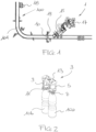
Fig. 1 schematically shows, in a top view, a portion of a transport line of a packaging system and the apparatus according to the invention located along said portion of said transport line; -
Fig. 2 shows in detail the transferring device of the apparatus according to the invention; -
Figs. 3a to 3e schematically show, in a top view, successive steps of the method according to the invention. - In the embodiment described hereinafter, reference will be made to an application of the method and the apparatus according to the invention to a bottling system, and more particularly to an inspection station of a bottling system. Yet, in no way such an application is to be intended in a limiting sense, and the invention can be applied in all situations where it is necessary or desirable to pick items from a transport line and to reintroduce items onto said transport line, more particularly when said transport line moves at high speed.
- Referring first to
Fig. 1 , there is schematically shown a portion of atransport line 100 of a bottling system, comprising aconveyor belt 101 on whichbottles 10 of plastic material (e.g. PET) advance in line and close to each other. - In such systems, in order to maintain a high productivity, the advance speed of
bottles 10 ontransport line 100 is very high, up to and beyond 70,000 bottles per hour. - In a manner known per se, the working stations of the bottling system, inside which the bottles undergo the desired operations (filling, capping, labelling and so on), are located along
transport line 100. - More particularly, along
transport line 100 an inspection station (not shown) can be provided, where a limited number of bottles, selected in spot manner (at random or according to a predetermined logic), undergo a number of checks in order to verify their conformity with predetermined quality standards. - The present invention comprises the steps of transferring the bottles selected for being inspected from
conveyor belt 101 oftransport line 100 to the inspection station, and transferring the bottles that have been inspected and deemed satisfactory from said inspection station to said conveyor belt of said transport line. - More particularly, the invention comprises the steps of picking a first bottle to be inspected from
transport line 100 in order to transfer it to the inspection station, and reintroducing a second bottle that has been already inspected in the inspection station and deemed satisfactory onto said transport line, into the gap left by said first bottle that has just been picked. Even more particularly, the invention comprises the steps of picking a first bottle to be inspected fromtransport line 100 and reintroducing a second bottle that has been already inspected and deemed satisfactory onto said transport line, at an immediately subsequent time, into the gap left by said first bottle that has just been picked. - Said invention is implemented by means of apparatus 1 shown in
Fig. 1 . - Said apparatus 1 comprises a transferring
device 3, shown in greater detail inFig. 2 . - Transferring
device 3 is provided with firstengaging elements 5 designed for selectively engaging/releasing a first bottle 10a. For instance, in the embodiment illustrated, the firstengaging elements 5 includefirst pliers 7, which can be closed in order to tighten about the neck of said first bottle 10a or can be opened to release the neck of said first bottle 10a. Transferringdevice 3 is also provided with secondengaging elements 9 designed for selectively engaging/releasing a second bottle 10b. In the embodiment illustrated, the secondengaging elements 9 includesecond pliers 11, which can be closed in order to tighten about the neck of said second bottle 10b or can be opened to release the neck of said second bottle 10b. - It is to be appreciated that, even if in the embodiment illustrated the first and the second
engaging elements - Actuators of any kind and sort, well in the reach of the person skilled in the art (for instance hydraulic actuators or pneumatic actuators), can be used to make the first and
second pliers - The first and the second
engaging elements interface plate 13. - Turning back to
Fig. 1 ,interface plate 13 is in turn secured to a supportingarm 15, more particularly a robotic supporting arm, carried by abase body 17. - Supporting
arm 15 is carried by saidbase body 17 so as to be movable at least in two different directions on a plane parallel to the plane on whichtransport line 100 advances. - More particularly, said supporting
arm 15 can be displaced in a first direction substantially parallel to the advance direction oftransport line 100 at the location of apparatus 1 according to the invention. More particularly, said supportingarm 15 can be displaced in a first direction substantially parallel to the advance direction oftransport line 100 synchronously with the advance oftransport line 100. - In this way, transferring
device 3 carried by supportingarm 15 can be kept substantially at the same point ofconveyor belt 101 while said conveyor belt is advancing at high speed. - Moreover, supporting
arm 15 can be displaced in a second direction transverse to the advance direction oftransport line 100 at the location of apparatus 1 according to the invention. - In this way, supporting
arm 15 can be moved from a first position, in which the firstengaging elements 5 of transferringdevice 3 are aligned withtransport line 100 for picking a first bottle from said transport line, to a second position in which the secondengaging elements 9 of said transferringdevice 3 are aligned withtransport line 100 for reintroducing a second bottle onto said transport line, into the gap left by said first bottle. - Supporting
arm 15 will also be movable in a third direction perpendicular to the plane on whichtransport line 100 lies, in order to be lowered relative to said transport line for engaging said first bottle to be picked from the transport line and to be lifted relative to said transport line after having released said second bottle to be reintroduced onto the transport line. - Actuators of any kind and sort, well in the reach of the person skilled in the art (for instance hydraulic actuators or pneumatic actuators) can be used to move supporting
arm 15. - Apparatus 1 will further comprise a controller for controlling the movements of supporting
arm 15, as well as for controlling switching of the first and secondengaging elements - In order to synchronise the movements of supporting
arm 15 withtransport line 100, apparatus 1 will preferably be equipped with a detecting device 18 (e.g. an encoder), preferably located upstream of said apparatus in the direction of advance of the transport line, capable of detecting the position and/or the speed oftransport line 100 and of transmitting the detected data to the controller of said apparatus 1. - Moreover, in order to properly control switching of the first and the second
engaging elements sensor 19, capable of detecting the passage of the bottles conveyed by said transport line and of transmitting such information to the controller of said apparatus 1. - In the embodiment illustrated, said sensor 19 (e.g. a photocell) is located along the transport line, upstream of said apparatus in the direction of advance of the transport line and at a known distance from said apparatus. Yet, in alternative embodiments of the invention, said sensor could be installed on the apparatus itself (e.g., it could be a video camera installed on supporting
arm 15 or base body 17). - It will be apparent to the person skilled in the art that detecting
device 18 andsensor 19 described above are not to be intended in a limiting sense and that any detecting device allowing detecting in real time the speed of the transport line and/or of the items advancing on the same line and the position of said items can be used. - Similarly, any identification device suitable to identify the specific item to be picked from the transport line can be used. Said identification device preferably will allow relating said specific article with its past "history" in the working stations upstream of apparatus 1, so that the checks carried out on said item can be used to perform possible corrections in the calibration of the instruments in said working stations.
- The operation of apparatus 1 will now be described with reference to
Figs. 3a to 3e . - In a first step, depicted in
Fig. 3a , apparatus 1 picks a bottle 10b that has been already inspected and deemed satisfactory from the inspection station, and the supporting arm moves from an idle position in the inspection station to a starting position, in which said supportingarm 15 is arranged so that the firstengaging elements 5 of transferringdevice 3 are aligned withtransport line 100. Moreoverr, the supporting arm is lifted relative to said transport line so that said firstengaging elements 5 are located above the top of the bottles advancing onconveyor belt 101 oftransport line 100. In such a first step,pliers 7 of the firstengaging elements 5 are in their releasing position and do not carry any bottle, whereaspliers 11 of the secondengaging elements 9 are in their engaging position and are tightened about the neck of bottle 10b. - From such a starting position, the supporting arm starts moving in a direction parallel to transport
line 100. Thanks to the information coming fromencoder 18 andphotocell 19, the supporting arm starts moving when bottle 10a to be picked and inspected is aligned below the firstengaging elements 5, and moves synchronously withconveyor belt 101 oftransport line 100. - In a second step, depicted in
Fig. 3b , the supporting arm, while moving parallel to transportline 100 and synchronously therewith, is lowered relative to saidtransport line 100, and the firstengaging elements 5 of transferringdevice 3 switch from their releasing position to their engaging position so that thefirst pliers 7 tighten about the neck of bottle 10a to be picked from the transport line. - In a third step, depicted in
Fig. 3c , supportingarm 15, while continuing moving in a direction substantially parallel to transportline 100 and synchronously therewith, is displaced in a second direction, transversely to transportline 100, so as to bring the secondengaging elements 9 of transferring device 3 (and hence bottle 10b to be reintroduced onto the transport line) in alignment with the conveyor belt of said transport line. - Since supporting
arm 15 moves synchronously with the transport line, bottle 10b carried by the secondengaging elements 9 will exactly occupy the gap left by bottle 10a that has just been picked by the firstengaging elements 5. - In a fourth step, depicted in
Fig. 3d , the secondengaging elements 9 of transferringdevice 3 move from their engaging position to their releasing position in order thesecond pliers 11 release the neck of bottle 10b to be reintroduced onto the transport line. - In a fifth and last step, depicted in
Fig. 3e , supportingarm 15 is lifted again relative to transportline 100, so as to transfer bottle 10a that has been picked from the transport line to the inspection station without interfering with the advance of the other bottles ontransport line 100. During this step, thesecond pliers 11 of the secondengaging elements 9 are in their releasing position and do not carry any bottle, whereas thefirst pliers 7 of the firstengaging elements 5 are in their engaging position and are tightened about the neck of bottle 10a. - From the above description, it is clearly apparent that bottle 10b that had been previously inspected and deemed satisfactory is reintroduced onto
transport line 100 into the gap just left by bottle 10a to be inspected, and resumes advancing ontransport line 100 substantially from the same position whence it had been previously picked for inspection. - It is also clearly apparent that, thanks to the replacement of bottle 10a that has been picked for the inspection with bottle 10b that had been previously inspected and deemed satisfactory, the bottles, when leaving the inspection station, are arranged onto the transport line without discontinuities and gaps.
- Bottle 10a that has been picked from the transport line for being inspected will undergo the specific checks provided for in the inspection station.
- To this end, in the embodiment illustrated, said bottle will be released by the
first pliers 7 of the firstengaging elements 5 of apparatus 1. If, at the end of the checks carried out in the inspection station, the bottle is deemed satisfactory, it will be loaded by apparatus 1 in order to be reintroduced onto the transport line, and to this end it will be seized by thesecond pliers 11 of the secondengaging elements 9 of said apparatus. - In an alternative embodiment, it might be deemed preferable that an item always interacts with the same engaging elements, both during picking from the transport line and during reintroduction onto said transport line. This maybe advantageous, for instance, if the operations to be performed on said item are very simple and can be carried out by keeping the item continuously in engagement with the apparatus according to the invention.
- In such an alternative embodiment, it is possible to envisage that the interface plate is mounted on the supporting arm so as to be rotatable by 180° about an axis perpendicular to the plane on which the transport line advances, so that the same engaging elements of the transferring device may be moved, depending on the operating step, to a proximal position or a distal position relative to the transport line.
- Should bottle 10a picked from the transport line for being inspected be judged unsatisfactory, it will be discarded.
- In a particularly simple embodiment of the invention, in such case a bottle that has been subsequently picked from the transport line will not be replaced.
- In an alternative embodiment of the invention, a supply of satisfactory bottles could be provided at the inspection station, so that, if bottle 10a is discarded, it can be replaced by a bottle taken form said supply. Such a measure advantageously allows avoiding the occurrence of gaps on the transport line downstream of apparatus 1 according to the invention and the occurrence of discontinuities in the bottle line advancing on said transport line.
- In a further alternative embodiment of the invention, it could be possible to envisage that also the bottles that have been checked and deemed unsatisfactory are reintroduced onto the transport line, after having been marked in some manner to denote that they are unsatisfactory in respect of one or more specific checks.
- From the above description, it will be clearly apparent to the person skilled in the art that the method and the apparatus according to the invention allow effectively achieving the objects stated above.
- Moreover, it will be clearly apparent to the person skilled in the art that in no way the embodiment as described and illustrated is to be intended in a limiting sense, and that several variations and modifications are possible, which are well in the reach of the person skilled in the art and anyway fall within the scope of the appended claims.
- For instance, even if in the embodiment described reference has been made to the application of the method and the apparatus according to the invention to a working station where only some items selected in spot manner are picked from the transport line, it cannot be excluded that said method and said apparatus can be used in applications in which all items advancing on the transport line are picked from the line and subsequently reintroduced thereon, the gap left by an item that has just been picked being exploited in order to reintroduce an item that had been previously picked and had already undergone the desired operations.
Claims (8)
- Method for transferring items from and to a transport line (100) along which a plurality of items (10) advance in line and close to each other, comprising the step of picking a first item (10a) of said plurality of items from said transport line (100), wherein said method comprises the step of placing a second item (10b) onto said transport line, into the gap left by said first item after picking thereof, characterized in that said second item (10b) is placed onto said transport line (100) at a time immediately following the time at which said first item (10a) has been picked from said transport line (100).
- Method according to claim 1, wherein said method comprises the steps of reintroducing onto said transport line a second item (10b) that had been previously picked from said transport line.
- Apparatus (1) for transferring items from and to a transport line (100) along which a plurality of items (10) advance in line and close to each other, said apparatus comprising a transferring device (3) wherein said transferring device (3) is provided with first engaging elements (5) designed for selectively engaging/releasing a first item (10a) of said plurality of items, which has to be picked from said transport line (100), and with second engaging elements (9) designed for selectively engaging/releasing a second item (10b), which has to be introduced onto said transport line (100), and wherein said transferring device (3) is carried by a supporting arm (15), characterized in that said supporting arm (15) is configured to move between a first position in which said first engaging elements (5) are aligned with a given point of said transport line for picking said first item (10a) from said transport line (100), and a second position in which said second engaging elements (9) are aligned with said given point of said transport line for introducing said second item (10b) onto said transport line (100), into the gap left by said first item and,
wherein said supporting arm (15) is movable along at least two different directions on a plane parallel to the plane on which said transport line (100) advances, a first one of said directions being substantially parallel to the advance direction of said transport line at the location of said apparatus (1) and a second one of said directions being transverse to the advance direction of said transport line at the location of said apparatus (1). - Apparatus (1) according to claim 3, wherein said supporting arm (15) is movable along said first direction, which is substantially parallel to the advance direction of said transport line at the location of said apparatus (1), at a speed that is substantially the same as the advancing speed of said transport line.
- Apparatus (1) according to claim 3 or 4, wherein said supporting arm (15) is also movable along a direction substantially perpendicular to the plane on which said transport line (100) advances.
- Apparatus (1) according to any of the claims 3 to 5, further comprising a controller for controlling the movements of said supporting arm (15) as well as for controlling the switching of said first and second engaging elements (5, 9) from their engaging position to their releasing position, and vice versa.
- Apparatus (1) according to claim 6, comprising a detecting device (18), suitable to detect the position and/or the speed of said transport line (100) and to transmit the detected data to said controller.
- Apparatus (1) according to claim 7, comprising a sensor (19), suitable to detect the passage of said items (10) carried by said transport line and to transmit the detected information to said controller.
Applications Claiming Priority (2)
| Application Number | Priority Date | Filing Date | Title |
|---|---|---|---|
| IT102017000072654A IT201700072654A1 (en) | 2017-06-28 | 2017-06-28 | Method and apparatus for transferring items to and from a transport line |
| PCT/IB2018/054797 WO2019003170A1 (en) | 2017-06-28 | 2018-06-28 | Method and apparatus for transferring items from and to a transport line |
Publications (2)
| Publication Number | Publication Date |
|---|---|
| EP3645432A1 EP3645432A1 (en) | 2020-05-06 |
| EP3645432B1 true EP3645432B1 (en) | 2023-06-07 |
Family
ID=60183005
Family Applications (1)
| Application Number | Title | Priority Date | Filing Date |
|---|---|---|---|
| EP18740913.1A Active EP3645432B1 (en) | 2017-06-28 | 2018-06-28 | Method and apparatus for transferring items from and to a transport line |
Country Status (9)
| Country | Link |
|---|---|
| US (1) | US11679942B2 (en) |
| EP (1) | EP3645432B1 (en) |
| CN (1) | CN111032540B (en) |
| BR (1) | BR112019028119B1 (en) |
| CA (1) | CA3067935A1 (en) |
| ES (1) | ES2954373T3 (en) |
| IT (1) | IT201700072654A1 (en) |
| MX (1) | MX2020000149A (en) |
| WO (1) | WO2019003170A1 (en) |
Families Citing this family (2)
| Publication number | Priority date | Publication date | Assignee | Title |
|---|---|---|---|---|
| CN112150048B (en) * | 2019-06-26 | 2024-06-18 | 北京京东乾石科技有限公司 | Transport control method, device, electronic equipment and storage medium |
| DE102023132891A1 (en) | 2023-11-24 | 2025-06-26 | Krones Aktiengesellschaft | Method and device for inspecting container closures attached to containers |
Family Cites Families (14)
| Publication number | Priority date | Publication date | Assignee | Title |
|---|---|---|---|---|
| US3951283A (en) * | 1973-04-17 | 1976-04-20 | Lingl Corporation | Method for blending bricks |
| JP2707088B2 (en) | 1987-11-20 | 1998-01-28 | 株式会社ニッテク | Container transfer method and apparatus |
| IT1305277B1 (en) * | 1998-10-20 | 2001-04-19 | Sipa Spa | DEVICE FOR THE IDENTIFICATION AND ELIMINATION OF PREFORMS HOOKED BY A CONTINUOUS TRANSFER LINE. |
| ITBO20000357A1 (en) * | 2000-06-16 | 2001-12-16 | Marchesini Group Spa | METHOD FOR THE TRANSFER OF BLISTER PACKAGES AND SIMILAR TO THE SUPPLY LINE OF A CARTONING MACHINE AND DEVICE FOR IMPLEMENTATION |
| US20040073333A1 (en) * | 2001-11-27 | 2004-04-15 | Brill Eric A. | System, method, and program for sorting objects |
| IT1393421B1 (en) * | 2009-03-20 | 2012-04-20 | Berchi Group S P A | GRIPPING HEAD IN PARTICULAR FOR PACKAGING SYSTEM AND ITS PACKAGING SYSTEM |
| EP2331300B1 (en) * | 2009-07-27 | 2013-08-21 | J&L Group International, LLC | System and methods for forming stacks |
| DE102011009181A1 (en) * | 2011-01-21 | 2012-07-26 | Krones Aktiengesellschaft | Device and method for transporting articles |
| JP5877657B2 (en) * | 2011-06-06 | 2016-03-08 | 倉敷紡績株式会社 | Method and apparatus for inspecting base of bottle can |
| US9611102B2 (en) * | 2012-10-26 | 2017-04-04 | Illinois Tool Works Inc. | Laning robot systems and methods |
| PL2801790T3 (en) | 2013-01-30 | 2017-04-28 | Nittan Valve Co., Ltd. | Workpiece inspection equipment |
| WO2014145412A2 (en) * | 2013-03-15 | 2014-09-18 | Illinois Tool Works Inc. | Continuous motion article arranging systems and methods |
| FR3026097B1 (en) | 2014-09-19 | 2017-09-29 | Visio Nerf | DEVICE FOR TRANSFERRING WORKPIECES |
| ITMI20150573A1 (en) | 2015-04-21 | 2016-10-21 | Ima Spa | CONTAINER TRANSFER DEVICE AND METHOD |
-
2017
- 2017-06-28 IT IT102017000072654A patent/IT201700072654A1/en unknown
-
2018
- 2018-06-28 US US16/626,945 patent/US11679942B2/en active Active
- 2018-06-28 ES ES18740913T patent/ES2954373T3/en active Active
- 2018-06-28 WO PCT/IB2018/054797 patent/WO2019003170A1/en not_active Ceased
- 2018-06-28 EP EP18740913.1A patent/EP3645432B1/en active Active
- 2018-06-28 BR BR112019028119-3A patent/BR112019028119B1/en active IP Right Grant
- 2018-06-28 MX MX2020000149A patent/MX2020000149A/en unknown
- 2018-06-28 CN CN201880043615.9A patent/CN111032540B/en active Active
- 2018-06-28 CA CA3067935A patent/CA3067935A1/en active Pending
Also Published As
| Publication number | Publication date |
|---|---|
| ES2954373T3 (en) | 2023-11-21 |
| US11679942B2 (en) | 2023-06-20 |
| WO2019003170A1 (en) | 2019-01-03 |
| US20200172349A1 (en) | 2020-06-04 |
| CN111032540A (en) | 2020-04-17 |
| CN111032540B (en) | 2021-12-07 |
| BR112019028119B1 (en) | 2023-09-26 |
| BR112019028119A2 (en) | 2020-07-28 |
| EP3645432A1 (en) | 2020-05-06 |
| IT201700072654A1 (en) | 2018-12-28 |
| CA3067935A1 (en) | 2019-01-03 |
| MX2020000149A (en) | 2020-07-22 |
Similar Documents
| Publication | Publication Date | Title |
|---|---|---|
| US11186444B2 (en) | Apparatus for unscrambling randomly arranged containers | |
| US11485586B2 (en) | Apparatus and method for handling piece goods moved one after another | |
| US9957117B2 (en) | Method for transferring articles | |
| CN111051225B (en) | Apparatus and method for orienting a cluster | |
| US20090205929A1 (en) | Article selection and loading system | |
| CA2839710C (en) | Robotic unscrambler and method | |
| US11053082B2 (en) | Method and apparatus for handling piece goods moved one after the other in at least one row | |
| EP4025354B1 (en) | Method and system of feeding groups of products to a processing unit | |
| US11897639B2 (en) | Automated packaging applicator system and methods of using the same | |
| US11530060B2 (en) | Handling apparatus and/or packaging apparatus and method used to package article groups in outer packaging | |
| US11932495B2 (en) | Robotic unscrambler | |
| US11679942B2 (en) | Method and apparatus for transferring items from and to a transport line | |
| US20030231317A1 (en) | System and device for detecting and separating out of position objects during manufacturing process | |
| CN209758431U (en) | Equipment for handling multiple items of a stream | |
| US20200182737A1 (en) | Leakage inspection device for container, leakage inspection method for container, and conveyed container processing device | |
| CN207275750U (en) | The pipeline system that a kind of yard of case and code bottle automatically switch |
Legal Events
| Date | Code | Title | Description |
|---|---|---|---|
| STAA | Information on the status of an ep patent application or granted ep patent |
Free format text: STATUS: UNKNOWN |
|
| STAA | Information on the status of an ep patent application or granted ep patent |
Free format text: STATUS: THE INTERNATIONAL PUBLICATION HAS BEEN MADE |
|
| PUAI | Public reference made under article 153(3) epc to a published international application that has entered the european phase |
Free format text: ORIGINAL CODE: 0009012 |
|
| STAA | Information on the status of an ep patent application or granted ep patent |
Free format text: STATUS: REQUEST FOR EXAMINATION WAS MADE |
|
| 17P | Request for examination filed |
Effective date: 20191223 |
|
| AK | Designated contracting states |
Kind code of ref document: A1 Designated state(s): AL AT BE BG CH CY CZ DE DK EE ES FI FR GB GR HR HU IE IS IT LI LT LU LV MC MK MT NL NO PL PT RO RS SE SI SK SM TR |
|
| AX | Request for extension of the european patent |
Extension state: BA ME |
|
| DAV | Request for validation of the european patent (deleted) | ||
| DAX | Request for extension of the european patent (deleted) | ||
| GRAP | Despatch of communication of intention to grant a patent |
Free format text: ORIGINAL CODE: EPIDOSNIGR1 |
|
| STAA | Information on the status of an ep patent application or granted ep patent |
Free format text: STATUS: GRANT OF PATENT IS INTENDED |
|
| INTG | Intention to grant announced |
Effective date: 20220922 |
|
| GRAS | Grant fee paid |
Free format text: ORIGINAL CODE: EPIDOSNIGR3 |
|
| GRAA | (expected) grant |
Free format text: ORIGINAL CODE: 0009210 |
|
| STAA | Information on the status of an ep patent application or granted ep patent |
Free format text: STATUS: THE PATENT HAS BEEN GRANTED |
|
| AK | Designated contracting states |
Kind code of ref document: B1 Designated state(s): AL AT BE BG CH CY CZ DE DK EE ES FI FR GB GR HR HU IE IS IT LI LT LU LV MC MK MT NL NO PL PT RO RS SE SI SK SM TR |
|
| REG | Reference to a national code |
Ref country code: GB Ref legal event code: FG4D |
|
| REG | Reference to a national code |
Ref country code: CH Ref legal event code: EP Ref country code: AT Ref legal event code: REF Ref document number: 1574456 Country of ref document: AT Kind code of ref document: T Effective date: 20230615 |
|
| REG | Reference to a national code |
Ref country code: DE Ref legal event code: R096 Ref document number: 602018051066 Country of ref document: DE |
|
| REG | Reference to a national code |
Ref country code: LT Ref legal event code: MG9D |
|
| REG | Reference to a national code |
Ref country code: NL Ref legal event code: MP Effective date: 20230607 |
|
| PG25 | Lapsed in a contracting state [announced via postgrant information from national office to epo] |
Ref country code: SE Free format text: LAPSE BECAUSE OF FAILURE TO SUBMIT A TRANSLATION OF THE DESCRIPTION OR TO PAY THE FEE WITHIN THE PRESCRIBED TIME-LIMIT Effective date: 20230607 Ref country code: NO Free format text: LAPSE BECAUSE OF FAILURE TO SUBMIT A TRANSLATION OF THE DESCRIPTION OR TO PAY THE FEE WITHIN THE PRESCRIBED TIME-LIMIT Effective date: 20230907 |
|
| P01 | Opt-out of the competence of the unified patent court (upc) registered |
Effective date: 20230926 |
|
| REG | Reference to a national code |
Ref country code: AT Ref legal event code: MK05 Ref document number: 1574456 Country of ref document: AT Kind code of ref document: T Effective date: 20230607 |
|
| REG | Reference to a national code |
Ref country code: ES Ref legal event code: FG2A Ref document number: 2954373 Country of ref document: ES Kind code of ref document: T3 Effective date: 20231121 |
|
| PG25 | Lapsed in a contracting state [announced via postgrant information from national office to epo] |
Ref country code: RS Free format text: LAPSE BECAUSE OF FAILURE TO SUBMIT A TRANSLATION OF THE DESCRIPTION OR TO PAY THE FEE WITHIN THE PRESCRIBED TIME-LIMIT Effective date: 20230607 Ref country code: NL Free format text: LAPSE BECAUSE OF FAILURE TO SUBMIT A TRANSLATION OF THE DESCRIPTION OR TO PAY THE FEE WITHIN THE PRESCRIBED TIME-LIMIT Effective date: 20230607 Ref country code: LV Free format text: LAPSE BECAUSE OF FAILURE TO SUBMIT A TRANSLATION OF THE DESCRIPTION OR TO PAY THE FEE WITHIN THE PRESCRIBED TIME-LIMIT Effective date: 20230607 Ref country code: LT Free format text: LAPSE BECAUSE OF FAILURE TO SUBMIT A TRANSLATION OF THE DESCRIPTION OR TO PAY THE FEE WITHIN THE PRESCRIBED TIME-LIMIT Effective date: 20230607 Ref country code: HR Free format text: LAPSE BECAUSE OF FAILURE TO SUBMIT A TRANSLATION OF THE DESCRIPTION OR TO PAY THE FEE WITHIN THE PRESCRIBED TIME-LIMIT Effective date: 20230607 Ref country code: GR Free format text: LAPSE BECAUSE OF FAILURE TO SUBMIT A TRANSLATION OF THE DESCRIPTION OR TO PAY THE FEE WITHIN THE PRESCRIBED TIME-LIMIT Effective date: 20230908 |
|
| PG25 | Lapsed in a contracting state [announced via postgrant information from national office to epo] |
Ref country code: FI Free format text: LAPSE BECAUSE OF FAILURE TO SUBMIT A TRANSLATION OF THE DESCRIPTION OR TO PAY THE FEE WITHIN THE PRESCRIBED TIME-LIMIT Effective date: 20230607 |
|
| PG25 | Lapsed in a contracting state [announced via postgrant information from national office to epo] |
Ref country code: SK Free format text: LAPSE BECAUSE OF FAILURE TO SUBMIT A TRANSLATION OF THE DESCRIPTION OR TO PAY THE FEE WITHIN THE PRESCRIBED TIME-LIMIT Effective date: 20230607 |
|
| PG25 | Lapsed in a contracting state [announced via postgrant information from national office to epo] |
Ref country code: IS Free format text: LAPSE BECAUSE OF FAILURE TO SUBMIT A TRANSLATION OF THE DESCRIPTION OR TO PAY THE FEE WITHIN THE PRESCRIBED TIME-LIMIT Effective date: 20231007 |
|
| PG25 | Lapsed in a contracting state [announced via postgrant information from national office to epo] |
Ref country code: SM Free format text: LAPSE BECAUSE OF FAILURE TO SUBMIT A TRANSLATION OF THE DESCRIPTION OR TO PAY THE FEE WITHIN THE PRESCRIBED TIME-LIMIT Effective date: 20230607 Ref country code: SK Free format text: LAPSE BECAUSE OF FAILURE TO SUBMIT A TRANSLATION OF THE DESCRIPTION OR TO PAY THE FEE WITHIN THE PRESCRIBED TIME-LIMIT Effective date: 20230607 Ref country code: RO Free format text: LAPSE BECAUSE OF FAILURE TO SUBMIT A TRANSLATION OF THE DESCRIPTION OR TO PAY THE FEE WITHIN THE PRESCRIBED TIME-LIMIT Effective date: 20230607 Ref country code: PT Free format text: LAPSE BECAUSE OF FAILURE TO SUBMIT A TRANSLATION OF THE DESCRIPTION OR TO PAY THE FEE WITHIN THE PRESCRIBED TIME-LIMIT Effective date: 20231009 Ref country code: IS Free format text: LAPSE BECAUSE OF FAILURE TO SUBMIT A TRANSLATION OF THE DESCRIPTION OR TO PAY THE FEE WITHIN THE PRESCRIBED TIME-LIMIT Effective date: 20231007 Ref country code: EE Free format text: LAPSE BECAUSE OF FAILURE TO SUBMIT A TRANSLATION OF THE DESCRIPTION OR TO PAY THE FEE WITHIN THE PRESCRIBED TIME-LIMIT Effective date: 20230607 Ref country code: CZ Free format text: LAPSE BECAUSE OF FAILURE TO SUBMIT A TRANSLATION OF THE DESCRIPTION OR TO PAY THE FEE WITHIN THE PRESCRIBED TIME-LIMIT Effective date: 20230607 Ref country code: AT Free format text: LAPSE BECAUSE OF FAILURE TO SUBMIT A TRANSLATION OF THE DESCRIPTION OR TO PAY THE FEE WITHIN THE PRESCRIBED TIME-LIMIT Effective date: 20230607 |
|
| REG | Reference to a national code |
Ref country code: CH Ref legal event code: PL |
|
| REG | Reference to a national code |
Ref country code: BE Ref legal event code: MM Effective date: 20230630 |
|
| PG25 | Lapsed in a contracting state [announced via postgrant information from national office to epo] |
Ref country code: PL Free format text: LAPSE BECAUSE OF FAILURE TO SUBMIT A TRANSLATION OF THE DESCRIPTION OR TO PAY THE FEE WITHIN THE PRESCRIBED TIME-LIMIT Effective date: 20230607 |
|
| PG25 | Lapsed in a contracting state [announced via postgrant information from national office to epo] |
Ref country code: LU Free format text: LAPSE BECAUSE OF NON-PAYMENT OF DUE FEES Effective date: 20230628 |
|
| REG | Reference to a national code |
Ref country code: DE Ref legal event code: R097 Ref document number: 602018051066 Country of ref document: DE |
|
| PG25 | Lapsed in a contracting state [announced via postgrant information from national office to epo] |
Ref country code: MC Free format text: LAPSE BECAUSE OF FAILURE TO SUBMIT A TRANSLATION OF THE DESCRIPTION OR TO PAY THE FEE WITHIN THE PRESCRIBED TIME-LIMIT Effective date: 20230607 |
|
| REG | Reference to a national code |
Ref country code: IE Ref legal event code: MM4A |
|
| PG25 | Lapsed in a contracting state [announced via postgrant information from national office to epo] |
Ref country code: MC Free format text: LAPSE BECAUSE OF FAILURE TO SUBMIT A TRANSLATION OF THE DESCRIPTION OR TO PAY THE FEE WITHIN THE PRESCRIBED TIME-LIMIT Effective date: 20230607 Ref country code: LU Free format text: LAPSE BECAUSE OF NON-PAYMENT OF DUE FEES Effective date: 20230628 |
|
| PLBE | No opposition filed within time limit |
Free format text: ORIGINAL CODE: 0009261 |
|
| STAA | Information on the status of an ep patent application or granted ep patent |
Free format text: STATUS: NO OPPOSITION FILED WITHIN TIME LIMIT |
|
| PG25 | Lapsed in a contracting state [announced via postgrant information from national office to epo] |
Ref country code: IE Free format text: LAPSE BECAUSE OF NON-PAYMENT OF DUE FEES Effective date: 20230628 |
|
| PG25 | Lapsed in a contracting state [announced via postgrant information from national office to epo] |
Ref country code: IE Free format text: LAPSE BECAUSE OF NON-PAYMENT OF DUE FEES Effective date: 20230628 Ref country code: DK Free format text: LAPSE BECAUSE OF FAILURE TO SUBMIT A TRANSLATION OF THE DESCRIPTION OR TO PAY THE FEE WITHIN THE PRESCRIBED TIME-LIMIT Effective date: 20230607 Ref country code: CH Free format text: LAPSE BECAUSE OF NON-PAYMENT OF DUE FEES Effective date: 20230630 |
|
| PG25 | Lapsed in a contracting state [announced via postgrant information from national office to epo] |
Ref country code: SI Free format text: LAPSE BECAUSE OF FAILURE TO SUBMIT A TRANSLATION OF THE DESCRIPTION OR TO PAY THE FEE WITHIN THE PRESCRIBED TIME-LIMIT Effective date: 20230607 |
|
| 26N | No opposition filed |
Effective date: 20240308 |
|
| GBPC | Gb: european patent ceased through non-payment of renewal fee |
Effective date: 20230907 |
|
| PG25 | Lapsed in a contracting state [announced via postgrant information from national office to epo] |
Ref country code: SI Free format text: LAPSE BECAUSE OF FAILURE TO SUBMIT A TRANSLATION OF THE DESCRIPTION OR TO PAY THE FEE WITHIN THE PRESCRIBED TIME-LIMIT Effective date: 20230607 Ref country code: BE Free format text: LAPSE BECAUSE OF NON-PAYMENT OF DUE FEES Effective date: 20230630 |
|
| PG25 | Lapsed in a contracting state [announced via postgrant information from national office to epo] |
Ref country code: GB Free format text: LAPSE BECAUSE OF NON-PAYMENT OF DUE FEES Effective date: 20230907 |
|
| PG25 | Lapsed in a contracting state [announced via postgrant information from national office to epo] |
Ref country code: GB Free format text: LAPSE BECAUSE OF NON-PAYMENT OF DUE FEES Effective date: 20230907 |
|
| PG25 | Lapsed in a contracting state [announced via postgrant information from national office to epo] |
Ref country code: BG Free format text: LAPSE BECAUSE OF FAILURE TO SUBMIT A TRANSLATION OF THE DESCRIPTION OR TO PAY THE FEE WITHIN THE PRESCRIBED TIME-LIMIT Effective date: 20230607 |
|
| PG25 | Lapsed in a contracting state [announced via postgrant information from national office to epo] |
Ref country code: BG Free format text: LAPSE BECAUSE OF FAILURE TO SUBMIT A TRANSLATION OF THE DESCRIPTION OR TO PAY THE FEE WITHIN THE PRESCRIBED TIME-LIMIT Effective date: 20230607 |
|
| PGFP | Annual fee paid to national office [announced via postgrant information from national office to epo] |
Ref country code: DE Payment date: 20250620 Year of fee payment: 8 |
|
| PGFP | Annual fee paid to national office [announced via postgrant information from national office to epo] |
Ref country code: FR Payment date: 20250522 Year of fee payment: 8 |
|
| PG25 | Lapsed in a contracting state [announced via postgrant information from national office to epo] |
Ref country code: CY Free format text: LAPSE BECAUSE OF FAILURE TO SUBMIT A TRANSLATION OF THE DESCRIPTION OR TO PAY THE FEE WITHIN THE PRESCRIBED TIME-LIMIT; INVALID AB INITIO Effective date: 20180628 |
|
| PG25 | Lapsed in a contracting state [announced via postgrant information from national office to epo] |
Ref country code: HU Free format text: LAPSE BECAUSE OF FAILURE TO SUBMIT A TRANSLATION OF THE DESCRIPTION OR TO PAY THE FEE WITHIN THE PRESCRIBED TIME-LIMIT; INVALID AB INITIO Effective date: 20180628 |
|
| PGFP | Annual fee paid to national office [announced via postgrant information from national office to epo] |
Ref country code: ES Payment date: 20250828 Year of fee payment: 8 |
|
| PGFP | Annual fee paid to national office [announced via postgrant information from national office to epo] |
Ref country code: IT Payment date: 20250617 Year of fee payment: 8 |
|
| PG25 | Lapsed in a contracting state [announced via postgrant information from national office to epo] |
Ref country code: TR Free format text: LAPSE BECAUSE OF FAILURE TO SUBMIT A TRANSLATION OF THE DESCRIPTION OR TO PAY THE FEE WITHIN THE PRESCRIBED TIME-LIMIT Effective date: 20230607 |