EP3645405B1 - System for assembling and filling electronic cigarettes - Google Patents
System for assembling and filling electronic cigarettes Download PDFInfo
- Publication number
- EP3645405B1 EP3645405B1 EP18747006.7A EP18747006A EP3645405B1 EP 3645405 B1 EP3645405 B1 EP 3645405B1 EP 18747006 A EP18747006 A EP 18747006A EP 3645405 B1 EP3645405 B1 EP 3645405B1
- Authority
- EP
- European Patent Office
- Prior art keywords
- conveyor
- electronic cigarette
- cigarette parts
- filling
- cartridges
- Prior art date
- Legal status (The legal status is an assumption and is not a legal conclusion. Google has not performed a legal analysis and makes no representation as to the accuracy of the status listed.)
- Active
Links
Images





Classifications
-
- A—HUMAN NECESSITIES
- A24—TOBACCO; CIGARS; CIGARETTES; SIMULATED SMOKING DEVICES; SMOKERS' REQUISITES
- A24F—SMOKERS' REQUISITES; MATCH BOXES; SIMULATED SMOKING DEVICES
- A24F40/00—Electrically operated smoking devices; Component parts thereof; Manufacture thereof; Maintenance or testing thereof; Charging means specially adapted therefor
- A24F40/70—Manufacture
-
- B—PERFORMING OPERATIONS; TRANSPORTING
- B65—CONVEYING; PACKING; STORING; HANDLING THIN OR FILAMENTARY MATERIAL
- B65B—MACHINES, APPARATUS OR DEVICES FOR, OR METHODS OF, PACKAGING ARTICLES OR MATERIALS; UNPACKING
- B65B43/00—Forming, feeding, opening or setting-up containers or receptacles in association with packaging
- B65B43/42—Feeding or positioning bags, boxes, or cartons in the distended, opened, or set-up state; Feeding preformed rigid containers, e.g. tins, capsules, glass tubes, glasses, to the packaging position; Locating containers or receptacles at the filling position; Supporting containers or receptacles during the filling operation
- B65B43/50—Feeding or positioning bags, boxes, or cartons in the distended, opened, or set-up state; Feeding preformed rigid containers, e.g. tins, capsules, glass tubes, glasses, to the packaging position; Locating containers or receptacles at the filling position; Supporting containers or receptacles during the filling operation using rotary tables or turrets
-
- A—HUMAN NECESSITIES
- A24—TOBACCO; CIGARS; CIGARETTES; SIMULATED SMOKING DEVICES; SMOKERS' REQUISITES
- A24F—SMOKERS' REQUISITES; MATCH BOXES; SIMULATED SMOKING DEVICES
- A24F40/00—Electrically operated smoking devices; Component parts thereof; Manufacture thereof; Maintenance or testing thereof; Charging means specially adapted therefor
- A24F40/10—Devices using liquid inhalable precursors
-
- B—PERFORMING OPERATIONS; TRANSPORTING
- B65—CONVEYING; PACKING; STORING; HANDLING THIN OR FILAMENTARY MATERIAL
- B65B—MACHINES, APPARATUS OR DEVICES FOR, OR METHODS OF, PACKAGING ARTICLES OR MATERIALS; UNPACKING
- B65B1/00—Packaging fluent solid material, e.g. powders, granular or loose fibrous material, loose masses of small articles, in individual containers or receptacles, e.g. bags, sacks, boxes, cartons, cans, or jars
- B65B1/04—Methods of, or means for, filling the material into the containers or receptacles
-
- B—PERFORMING OPERATIONS; TRANSPORTING
- B65—CONVEYING; PACKING; STORING; HANDLING THIN OR FILAMENTARY MATERIAL
- B65B—MACHINES, APPARATUS OR DEVICES FOR, OR METHODS OF, PACKAGING ARTICLES OR MATERIALS; UNPACKING
- B65B1/00—Packaging fluent solid material, e.g. powders, granular or loose fibrous material, loose masses of small articles, in individual containers or receptacles, e.g. bags, sacks, boxes, cartons, cans, or jars
- B65B1/30—Devices or methods for controlling or determining the quantity or quality or the material fed or filled
- B65B1/32—Devices or methods for controlling or determining the quantity or quality or the material fed or filled by weighing
-
- B—PERFORMING OPERATIONS; TRANSPORTING
- B65—CONVEYING; PACKING; STORING; HANDLING THIN OR FILAMENTARY MATERIAL
- B65B—MACHINES, APPARATUS OR DEVICES FOR, OR METHODS OF, PACKAGING ARTICLES OR MATERIALS; UNPACKING
- B65B43/00—Forming, feeding, opening or setting-up containers or receptacles in association with packaging
- B65B43/42—Feeding or positioning bags, boxes, or cartons in the distended, opened, or set-up state; Feeding preformed rigid containers, e.g. tins, capsules, glass tubes, glasses, to the packaging position; Locating containers or receptacles at the filling position; Supporting containers or receptacles during the filling operation
- B65B43/52—Feeding or positioning bags, boxes, or cartons in the distended, opened, or set-up state; Feeding preformed rigid containers, e.g. tins, capsules, glass tubes, glasses, to the packaging position; Locating containers or receptacles at the filling position; Supporting containers or receptacles during the filling operation using roller-ways or endless conveyors
-
- B—PERFORMING OPERATIONS; TRANSPORTING
- B65—CONVEYING; PACKING; STORING; HANDLING THIN OR FILAMENTARY MATERIAL
- B65B—MACHINES, APPARATUS OR DEVICES FOR, OR METHODS OF, PACKAGING ARTICLES OR MATERIALS; UNPACKING
- B65B43/00—Forming, feeding, opening or setting-up containers or receptacles in association with packaging
- B65B43/42—Feeding or positioning bags, boxes, or cartons in the distended, opened, or set-up state; Feeding preformed rigid containers, e.g. tins, capsules, glass tubes, glasses, to the packaging position; Locating containers or receptacles at the filling position; Supporting containers or receptacles during the filling operation
- B65B43/54—Means for supporting containers or receptacles during the filling operation
- B65B43/60—Means for supporting containers or receptacles during the filling operation rotatable
-
- B—PERFORMING OPERATIONS; TRANSPORTING
- B65—CONVEYING; PACKING; STORING; HANDLING THIN OR FILAMENTARY MATERIAL
- B65B—MACHINES, APPARATUS OR DEVICES FOR, OR METHODS OF, PACKAGING ARTICLES OR MATERIALS; UNPACKING
- B65B65/00—Details peculiar to packaging machines and not otherwise provided for; Arrangements of such details
- B65B65/003—Packaging lines, e.g. general layout
-
- B—PERFORMING OPERATIONS; TRANSPORTING
- B65—CONVEYING; PACKING; STORING; HANDLING THIN OR FILAMENTARY MATERIAL
- B65G—TRANSPORT OR STORAGE DEVICES, e.g. CONVEYORS FOR LOADING OR TIPPING, SHOP CONVEYOR SYSTEMS OR PNEUMATIC TUBE CONVEYORS
- B65G37/00—Combinations of mechanical conveyors of the same kind, or of different kinds, of interest apart from their application in particular machines or use in particular manufacturing processes
-
- B—PERFORMING OPERATIONS; TRANSPORTING
- B65—CONVEYING; PACKING; STORING; HANDLING THIN OR FILAMENTARY MATERIAL
- B65B—MACHINES, APPARATUS OR DEVICES FOR, OR METHODS OF, PACKAGING ARTICLES OR MATERIALS; UNPACKING
- B65B1/00—Packaging fluent solid material, e.g. powders, granular or loose fibrous material, loose masses of small articles, in individual containers or receptacles, e.g. bags, sacks, boxes, cartons, cans, or jars
-
- B—PERFORMING OPERATIONS; TRANSPORTING
- B65—CONVEYING; PACKING; STORING; HANDLING THIN OR FILAMENTARY MATERIAL
- B65B—MACHINES, APPARATUS OR DEVICES FOR, OR METHODS OF, PACKAGING ARTICLES OR MATERIALS; UNPACKING
- B65B3/00—Packaging plastic material, semiliquids, liquids or mixed solids and liquids, in individual containers or receptacles, e.g. bags, sacks, boxes, cartons, cans, or jars
-
- B—PERFORMING OPERATIONS; TRANSPORTING
- B65—CONVEYING; PACKING; STORING; HANDLING THIN OR FILAMENTARY MATERIAL
- B65G—TRANSPORT OR STORAGE DEVICES, e.g. CONVEYORS FOR LOADING OR TIPPING, SHOP CONVEYOR SYSTEMS OR PNEUMATIC TUBE CONVEYORS
- B65G2201/00—Indexing codes relating to handling devices, e.g. conveyors, characterised by the type of product or load being conveyed or handled
- B65G2201/02—Articles
- B65G2201/0235—Containers
- B65G2201/0261—Puck as article support
Definitions
- This invention addresses the technical field of electronic cigarettes.
- the invention relates to a system for assembling and filling electronic cigarettes.
- the system further comprises
- the degree of precision required for one operation may be very different from that required for other operations and managing them all may be very complex.
- the aim of this invention is to overcome the above mentioned drawbacks.
- this invention allows increasing overall productivity not only because it allows assembling and filling two groups of electronic cigarettes simultaneously but also because it offers a high level of flexibility.
- the numeral 1 denotes a system according to this invention, for assembling and filling electronic cigarette parts comprising cartridges.
- electronic cigarette parts is used to mean complete electronic cigarettes or components of electronic cigarettes, in both cases comprising cartridges (which need to be filled).
- the system 1 also comprises a first group of working stations 21 for assembling and/or inspecting the electronic cigarette parts conveyed along the first conveyor 2 and held by the first group of carrier units 20.
- the system 1 also comprises a second, endless linear motor conveyor 4, downstream of the first conveyor 2; and a second group of carrier units 40 connected to the second conveyor 4 in order to be movable along the second conveyor 4 independently of one another.
- Each carrier unit of the second group of carrier units 40 is configured to receive and hold electronic cigarette parts.
- the system 1 also comprises a second group of working stations 41 for assembling and/or inspecting the electronic cigarette parts conveyed along the second conveyor 4; and held by the second group of working units 40.
- the system 1 further comprises a filling station S5 which is interposed between the first conveyor 2 and the second conveyor 4 and which is configured to receive the electronic cigarette parts at a loading zone 50 from the first conveyor 2, to fill the respective cartridges, and, at an unloading zone 51, to feed the electronic cigarette parts with the respective filled cartridges towards the second conveyor 4.
- a filling station S5 which is interposed between the first conveyor 2 and the second conveyor 4 and which is configured to receive the electronic cigarette parts at a loading zone 50 from the first conveyor 2, to fill the respective cartridges, and, at an unloading zone 51, to feed the electronic cigarette parts with the respective filled cartridges towards the second conveyor 4.
- the system 1 it is possible to sequentially perform a series of operations which require different degrees of precision, even very different from each other.
- the first group of working stations 21 and the second group of working stations 41 perform assembly / inspection operations on the electronic cigarette parts: these operations are often complicate and require a high level of precision (because they involve manipulating/assembling very small parts/components).
- the cartridges are filled by the filling station S5, which is interposed between the first conveyor 2 and the second conveyor 4: this operation is much simpler than the assembling/inspection operations and, compared to these, require a lower level of precision.
- first group of working stations 21 and the second group of working stations 41 are located at the upper section of the first conveyor 2 and of the second conveyor 4, respectively.
- the first group of carrier units 20 and the second group of carrier units 40 have magnets (not shown) mounted on them to allow movement along the first conveyor 2 and along the second conveyor 4.
- the system 1 further comprises a first weighing station S1 (illustrated schematically), disposed upstream of the loading zone 50 of the filling station S5 to allow weighing the electronic cigarette parts conveyed by the first conveyor 2, before the cartridges are filled; and a second weighing a station S2 (illustrated schematically), disposed downstream of the unloading zone 51 of the filling station S5 to allow weighing the electronic cigarette parts leaving the filling station S5, after the cartridges have been filled and before transfer to the second conveyor 4.
- a first weighing station S1 illustrated schematically
- a second weighing a station S2 illustrated schematically
- the system 1 may comprise a processing unit (not illustrated) capable of calculating the difference, for each cartridge, between the weight measured at the first weighing station S1 and the weight measured at the second weighing station S2.
- the processing unit is also capable of comparing the quantity of product filled into each cartridge with a reference value. If the value measured does not coincide with the reference value, the processing unit flags the cartridge as "non-conforming" and causes it to rejected at a dedicated station (not illustrated).
- the quantity of product filled into each cartridge is measured at a single measuring station located downstream of the unloading zone of the filling station, which involves, for example, a volumetric or pressure measurement of each cartridge (using measuring methods not described in this specification).
- a processing unit is provided in this case, too, which is capable of comparing the quantity of product filled into each cartridge with a reference value, causing the cartridge to be rejected if it is found to be "non-conforming".
- the filling station S5 comprises housings 6 positioned along a circular path 10 and rotatable in a first rotation direction W about the axis of the circular path 10 to receive and hold the electronic cigarette parts; and a plurality of filling heads 7 for filling the cartridges of the electronic cigarette parts when disposed at the housings 6.
- the filling heads 7 are mounted to a carousel having a circular profile, positioned above the housings 6 and rotatable about its axis in the first rotation direction W simultaneously with the housings 6.
- the axis of rotation of the carousel is preferably parallel to, and still more preferably, coincident with, the axis of rotation of the circular profile 10 defined by the housings 6.
- the number of filling heads 7 is equal to the number of housings 6 which receive the electronic cigarette parts (comprising the cartridges).
- the filling station S5 is a horizontally oriented carousel which rotates continuously about the respective vertical axis.
- the first group of filling heads 7 is also movable axially between an idle position and an operating position, where the operating position is axially below the idle position and where the electronic cigarette parts are filled.
- the filling heads 7 are mounted to a sector 8 that is rotatable about a rotation axis (which, in the drawings, is represented as a circular sector) in the first rotation direction W while the electronic cigarette parts are being filled, performing a forward stroke, and in a second rotation direction, opposite to the first rotation direction W, after the electronic cigarette parts have been filled, performing a backward stroke.
- a rotation axis which, in the drawings, is represented as a circular sector
- the axis of rotation of the sector 8 is a vertical axis.
- the axis of rotation is preferably parallel to, and still more preferably, coincident with, the axis of rotation of the circular profile 10 defined by the housings 6.
- the filling heads move with alternating rotary motion along respective forward strokes (during which they fill the cartridges) and return strokes (during which they are idle, that is to say, they do not fill the electronic cigarettes) (rotational following).
- the filling heads 7 are also movable axially between an idle position and an operating position, where the operating position is axially below the idle position and where the electronic cigarette parts are filled.
- corresponding transfer devices 500, 510 - for example of the star wheel type - which transfer the electronic cigarette parts into the housings 6 and disengage them from the housings 6.
- the filling station S5 comprises a row of housings 6 (not visible in the accompanying drawings) to receive the electronic cigarette parts and movable translationally in first translation direction T1 and in a second translation direction T2, opposite to the first translation direction T1.
- the filling station S5 comprises a plurality of filling heads 7 - for example, a row of filling heads 7 - for filling the electronic cigarette parts and movable translationally in the first translation direction T1 and in the second translation direction T2, simultaneously with the housings 6 (linear following).
- the filling heads 7 are also movable vertically between an idle position and an operating position, where the operating position is axially below the idle position and where the electronic cigarette parts (cartridges) are filled.
- the system 1 comprises a plurality of support containers (also known as buckets, not illustrated) for supporting the electronic cigarette parts while the cartridges are being filled in the filling station S5.
- support containers also known as buckets, not illustrated
- Use of these support containers is necessary because the cigarette parts, and in particular, the cartridges to be filled, are of reduced size, and in some cases are fragile or have unstable positions which would make them difficult to fill.
- the system 1 also comprises first pickup means 9 for picking up the electronic cigarette parts from the first group of carrier units 20 as they leave the first conveyor 2 and for placing them in the containers.
- the second embodiment of the system 1 also comprises second pickup means 90 for picking up the electronic cigarette parts from the containers as they leave the filling station S5, and placing them at the second group of carrier units 40 as they enter the second conveyor 4.
- the first pickup means 9 and the second pickup means 90 comprise a plurality of robotized arms (also known as "pick and place arms").
- the system 1 further comprises an auxiliary path P2 connecting the unloading zone 51 with the loading zone 50 of the filling station S5, on the outside of the filling station S5.
- the support containers are conveyed along the auxiliary path P2 (which comprises a rail) after the electronic cigarette parts have been picked up from the containers.
- the first pickup means 9 therefore pick up the electronic cigarette parts which have been conveyed along the first conveyor 2 (at an outfeed zone thereof) and place them in the containers on the first auxiliary path (before being placed in the containers, the electronic cigarette parts are, if necessary, weighed at the first weighing station S1, as described above).
- the support containers then move along one stretch of the auxiliary path P2 and reach the loading zone 50 of the filling station.
- the containers are held in the housings 6 of the filling station while the cartridges are filled.
- the second pickup means 90 pick up the electronic cigarette parts and place them at the second group of carrier units 40, that is, on the second conveyor 4 (at a respective infeed zone).
- the empty containers move along the auxiliary path P2 from the unloading zone 51 to the loading zone 50, where they are once again filled by the first pickup means 9.
- the system 1 is advantageously made even more flexible.
- the first conveyor, the filling station S5 and the second conveyor 4 are disposed in such a way that the electronic cigarette parts travel along a C-shaped path P1 passing through the system 1 itself.
- the first conveyor, the filling station S5 and the second conveyor 4 are disposed in such a way that the electronic cigarette parts travel along an I-shaped path P1 passing through the system 1 itself.
- the system 1 allows the layout to be configured according to the available space, making it particularly flexible and versatile.
- the system 1 is advantageously made even more flexible.
Landscapes
- Engineering & Computer Science (AREA)
- Mechanical Engineering (AREA)
- Microelectronics & Electronic Packaging (AREA)
- Quality & Reliability (AREA)
- Wrapping Of Specific Fragile Articles (AREA)
- Basic Packing Technique (AREA)
- Specific Conveyance Elements (AREA)
Description
- This invention addresses the technical field of electronic cigarettes.
- More specifically, the invention relates to a system for assembling and filling electronic cigarettes.
- As is known, electronic cigarettes are made up of different components which are assembled to each other.
- In recent times, the production of electronic cigarettes has become more and more automated; in particular, automatic stations are dedicated to operations which differ greatly from each other: for example, assembling the electronic components, filling the cartridges with the liquid to be vaporized, inspecting the assembled groups, etc. Document
WO 2015/140768 discloses a system for assembling electronic cigarette parts comprising cartridges and for filling said cartridges, the system comprising: - a first, endless linear motor conveyor and being configured to convey, receive and hold electronic cigarette parts;
- a first group of working stations for assembling and/or inspecting the electronic cigarette parts conveyed along the first conveyor
- a second, endless linear motor conveyor located downstream of the first conveyor and being configured to convey, receive and hold electronic cigarette parts;
- a second group of working stations for assembling and/or inspecting the electronic cigarette parts conveyed along the second conveyor; and
- a filling station, disposed between the first conveyor and the second conveyor to
- receive the electronic cigarette parts at a loading zone, from the first conveyor
- fill the respective cartridges, and, at an unloading zone,
- feed the electronic cigarette parts with the respective filled cartridges towards the second conveyor.
- The system further comprises
- a plurality of support containers for supporting the electronic cigarette parts while the cartridges are being filled in the filling station; and
- an auxiliary path connecting the unloading zone with the loading zone of the filling station, on the outside of the filling station; said support containers being conveyed along the auxiliary path after the electronic cigarette parts have been picked up from the containers.
- The degree of precision required for one operation may be very different from that required for other operations and managing them all may be very complex.
- Some operations, such as filling the cartridges, for example, may indeed be very simple and do not require particularly high levels of precision. Other operations, such as assembling, on the other hand, are clearly more complex and require very high levels of precision.
- In many cases, therefore, two or more systems placed in parallel are necessary to perform different operations at different times. As a result, assembling and filling electronic cigarettes require considerable lengths of time and the overall dimensions of the systems used for these purposes are very often also considerable.
- The aim of this invention is to overcome the above mentioned drawbacks.
- This aim is achieved by proposing a system for assembling and filling electronic cigarettes according to the accompanying claims.
- Advantageously, this invention allows increasing overall productivity not only because it allows assembling and filling two groups of electronic cigarettes simultaneously but also because it offers a high level of flexibility.
- Further advantages are more apparent in the specification which follows, with reference to the accompanying drawings, in which:
-
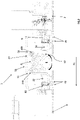
Figure 1 is a schematic plan view of a system according to the invention, in a first embodiment of it; -
Figure 2 is an enlarged view of the system ofFigure 1 ; -
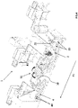
Figure 3 is a perspective view of the system ofFigure 1 ; -
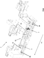
Figure 4 is a schematic perspective view of a system according to the invention, in a second embodiment of it; -
Figure 5 is an enlarged view ofFigure 4 ; -
Figures 6 and7 are two views like those ofFigure 4 andFigure 5 , respectively, according to a third embodiment of the invention; -
Figures 8 and9 are, respectively, a schematic plan view and a schematic perspective view of the second embodiment of the system of the invention in a variant that differs from what is illustrated inFigure 4 andFigure 5 . - With reference to the accompanying drawings, the
numeral 1 denotes a system according to this invention, for assembling and filling electronic cigarette parts comprising cartridges. - The expression "electronic cigarette parts" is used to mean complete electronic cigarettes or components of electronic cigarettes, in both cases comprising cartridges (which need to be filled).
- The
system 1 for assembling electronic cigarette parts comprising cartridges and for filling the cartridges comprises a first, endlesslinear motor conveyor 2; a first group ofcarrier units 20 connected to thefirst conveyor 2 in order to be movable along thefirst conveyor 2 independently of one another. Each working unit of the first group ofcarrier units 20 is configured to receive and hold electronic cigarette parts. Thesystem 1 also comprises a first group ofworking stations 21 for assembling and/or inspecting the electronic cigarette parts conveyed along thefirst conveyor 2 and held by the first group ofcarrier units 20. - The
system 1 also comprises a second, endlesslinear motor conveyor 4, downstream of thefirst conveyor 2; and a second group ofcarrier units 40 connected to thesecond conveyor 4 in order to be movable along thesecond conveyor 4 independently of one another. Each carrier unit of the second group ofcarrier units 40 is configured to receive and hold electronic cigarette parts. - The
system 1 also comprises a second group ofworking stations 41 for assembling and/or inspecting the electronic cigarette parts conveyed along thesecond conveyor 4; and held by the second group of workingunits 40. - The
system 1 further comprises a filling station S5 which is interposed between thefirst conveyor 2 and thesecond conveyor 4 and which is configured to receive the electronic cigarette parts at aloading zone 50 from thefirst conveyor 2, to fill the respective cartridges, and, at anunloading zone 51, to feed the electronic cigarette parts with the respective filled cartridges towards thesecond conveyor 4. - Advantageously, thanks to the
system 1, it is possible to sequentially perform a series of operations which require different degrees of precision, even very different from each other. Specifically, the first group ofworking stations 21 and the second group ofworking stations 41 perform assembly / inspection operations on the electronic cigarette parts: these operations are often complicate and require a high level of precision (because they involve manipulating/assembling very small parts/components). - The cartridges, on the other hand, are filled by the filling station S5, which is interposed between the
first conveyor 2 and the second conveyor 4: this operation is much simpler than the assembling/inspection operations and, compared to these, require a lower level of precision. - The above mentioned operations, with such different technical and management requirements, are perfectly integrated in the
system 1. This reduces production times compared to parallel systems, where the electronic cigarettes must be transferred from/to the assembling stations to/from the filling station. Furthermore, the overall dimensions of thesystem 1 are particularly limited. - In the accompanying drawings, the first group of
working stations 21 and the second group of working stations 41 (represented schematically and by way of example) are located at the upper section of thefirst conveyor 2 and of thesecond conveyor 4, respectively. In a variant not illustrated, there may be other working stations - inspection stations, for example - at the bottom section of thefirst conveyor 2 and/or of thesecond conveyor 4. That way, the overall dimensions can be even further reduced. - The first group of
carrier units 20 and the second group ofcarrier units 40 have magnets (not shown) mounted on them to allow movement along thefirst conveyor 2 and along thesecond conveyor 4. - In the preferred embodiment illustrated in
Figures 1-5 , thesystem 1 further comprises a first weighing station S1 (illustrated schematically), disposed upstream of theloading zone 50 of the filling station S5 to allow weighing the electronic cigarette parts conveyed by thefirst conveyor 2, before the cartridges are filled; and a second weighing a station S2 (illustrated schematically), disposed downstream of theunloading zone 51 of the filling station S5 to allow weighing the electronic cigarette parts leaving the filling station S5, after the cartridges have been filled and before transfer to thesecond conveyor 4. - It is thus advantageously possible to control the quantity of product filled into the cartridges (which may be a liquid or a powder). For this purpose, the
system 1 may comprise a processing unit (not illustrated) capable of calculating the difference, for each cartridge, between the weight measured at the first weighing station S1 and the weight measured at the second weighing station S2. The processing unit is also capable of comparing the quantity of product filled into each cartridge with a reference value. If the value measured does not coincide with the reference value, the processing unit flags the cartridge as "non-conforming" and causes it to rejected at a dedicated station (not illustrated). - In an alternative embodiment, not illustrated, the quantity of product filled into each cartridge is measured at a single measuring station located downstream of the unloading zone of the filling station, which involves, for example, a volumetric or pressure measurement of each cartridge (using measuring methods not described in this specification). In the same way as what is described above, a processing unit is provided in this case, too, which is capable of comparing the quantity of product filled into each cartridge with a reference value, causing the cartridge to be rejected if it is found to be "non-conforming".
- With reference in particular to the embodiments illustrated in
Figures 1-5 and8-9 , the filling station S5 compriseshousings 6 positioned along acircular path 10 and rotatable in a first rotation direction W about the axis of thecircular path 10 to receive and hold the electronic cigarette parts; and a plurality offilling heads 7 for filling the cartridges of the electronic cigarette parts when disposed at thehousings 6. - In the embodiment of the invention illustrated in
Figures 4 ,5 ,8 ,9 , thefilling heads 7 are mounted to a carousel having a circular profile, positioned above thehousings 6 and rotatable about its axis in the first rotation direction W simultaneously with thehousings 6. - The axis of rotation of the carousel is preferably parallel to, and still more preferably, coincident with, the axis of rotation of the
circular profile 10 defined by thehousings 6. - According to the embodiment just described, the number of filling heads 7 is equal to the number of
housings 6 which receive the electronic cigarette parts (comprising the cartridges). - In this embodiment, therefore, the filling station S5 is a horizontally oriented carousel which rotates continuously about the respective vertical axis. For example, the first group of filling
heads 7 is also movable axially between an idle position and an operating position, where the operating position is axially below the idle position and where the electronic cigarette parts are filled. - In the embodiment illustrated in
Figures 1-3 , the filling heads 7 are mounted to asector 8 that is rotatable about a rotation axis (which, in the drawings, is represented as a circular sector) in the first rotation direction W while the electronic cigarette parts are being filled, performing a forward stroke, and in a second rotation direction, opposite to the first rotation direction W, after the electronic cigarette parts have been filled, performing a backward stroke. - Again with reference to
Figures 1-3 , the axis of rotation of thesector 8 is a vertical axis. The axis of rotation is preferably parallel to, and still more preferably, coincident with, the axis of rotation of thecircular profile 10 defined by thehousings 6. - In this embodiment, unlike the embodiment described previously, the filling heads move with alternating rotary motion along respective forward strokes (during which they fill the cartridges) and return strokes (during which they are idle, that is to say, they do not fill the electronic cigarettes) (rotational following).
- For example, the filling heads 7 are also movable axially between an idle position and an operating position, where the operating position is axially below the idle position and where the electronic cigarette parts are filled. With reference to the two embodiments described above, there are provided at the
loading zone 50 and at the unloadingzone 51, correspondingtransfer devices 500, 510 - for example of the star wheel type - which transfer the electronic cigarette parts into thehousings 6 and disengage them from thehousings 6. - In the embodiment illustrated in
Figures 6 and7 , the filling station S5 comprises a row of housings 6 (not visible in the accompanying drawings) to receive the electronic cigarette parts and movable translationally in first translation direction T1 and in a second translation direction T2, opposite to the first translation direction T1. The filling station S5 comprises a plurality of filling heads 7 - for example, a row of filling heads 7 - for filling the electronic cigarette parts and movable translationally in the first translation direction T1 and in the second translation direction T2, simultaneously with the housings 6 (linear following). - In this case, too, the filling heads 7 are also movable vertically between an idle position and an operating position, where the operating position is axially below the idle position and where the electronic cigarette parts (cartridges) are filled.
- Preferably, the
system 1 comprises a plurality of support containers (also known as buckets, not illustrated) for supporting the electronic cigarette parts while the cartridges are being filled in the filling station S5. Use of these support containers is necessary because the cigarette parts, and in particular, the cartridges to be filled, are of reduced size, and in some cases are fragile or have unstable positions which would make them difficult to fill. - The
system 1 also comprises first pickup means 9 for picking up the electronic cigarette parts from the first group ofcarrier units 20 as they leave thefirst conveyor 2 and for placing them in the containers. The second embodiment of thesystem 1 also comprises second pickup means 90 for picking up the electronic cigarette parts from the containers as they leave the filling station S5, and placing them at the second group ofcarrier units 40 as they enter thesecond conveyor 4. As shown in the drawings, the first pickup means 9 and the second pickup means 90 comprise a plurality of robotized arms (also known as "pick and place arms"). - With reference to the accompanying drawings, the
system 1 further comprises an auxiliary path P2 connecting the unloadingzone 51 with theloading zone 50 of the filling station S5, on the outside of the filling station S5. The support containers are conveyed along the auxiliary path P2 (which comprises a rail) after the electronic cigarette parts have been picked up from the containers. - The first pickup means 9 therefore pick up the electronic cigarette parts which have been conveyed along the first conveyor 2 (at an outfeed zone thereof) and place them in the containers on the first auxiliary path (before being placed in the containers, the electronic cigarette parts are, if necessary, weighed at the first weighing station S1, as described above). The support containers then move along one stretch of the auxiliary path P2 and reach the
loading zone 50 of the filling station. The containers are held in thehousings 6 of the filling station while the cartridges are filled. Next, once filling is over, the containers with the electronic cigarette parts inside them reach theunloading zone 51 and the second pickup means 90 pick up the electronic cigarette parts and place them at the second group ofcarrier units 40, that is, on the second conveyor 4 (at a respective infeed zone). At this point, the empty containers move along the auxiliary path P2 from the unloadingzone 51 to theloading zone 50, where they are once again filled by the first pickup means 9. - By suitably setting up different working stations along the first and
second conveyors system 1 is advantageously made even more flexible. - As shown in
Figures 8 and9 , the first conveyor, the filling station S5 and thesecond conveyor 4 are disposed in such a way that the electronic cigarette parts travel along a C-shaped path P1 passing through thesystem 1 itself. - Alternatively, as shown in
Figures 1-7 , the first conveyor, the filling station S5 and thesecond conveyor 4 are disposed in such a way that the electronic cigarette parts travel along an I-shaped path P1 passing through thesystem 1 itself. - Advantageously, the
system 1 allows the layout to be configured according to the available space, making it particularly flexible and versatile. - By suitably setting up different working stations along the first and
second conveyors system 1 is advantageously made even more flexible.
Claims (7)
- A system (1) for assembling electronic cigarette parts comprising cartridges and for filling said cartridges, the system (1) comprising:a first, endless linear motor conveyor (2); a first group of carrier units (20) connected to the first conveyor (2) in order to be movable independently of one another along the first conveyor (2); each carrier unit (20) being configured to receive and hold electronic cigarette parts;a first group of working stations (21) for assembling and/or inspecting the electronic cigarette parts conveyed along the first conveyor (2) and held by the first group of carrier units (20);a second, endless linear motor conveyor (4), located downstream of the first conveyor (2); a second group of carrier units (40) connected to the second conveyor (4) in order to be movable independently of one another along the second conveyor (4); each carrier unit (40) being configured to receive and hold electronic cigarette parts;a second group of working stations (41) for assembling and/or inspecting the electronic cigarette parts conveyed along the second conveyor (4); andheld by the second group of carrier units (40);and a filling station (S5), disposed between the first conveyor (2) and the second conveyor (4) to receive the electronic cigarette parts at a loading zone (50) from the first conveyor (2), fill the respective cartridges, and, at an unloading zone (51), feed the electronic cigarette parts with the respective filled cartridges towards the second conveyor (4);wherein the filling station (S5) comprises housings (6) positioned along a circular path (10) and rotatable in a first rotation direction (W) about the axis of the circular path (10) to receive and hold the electronic cigarette parts;and a plurality of filling heads (7) for filling the cartridges of the electronic cigarette parts when disposed at the housings (6); andthe system (1) further comprising a plurality of support containers designed to be held in the housings (6) of the filling station (S5) for supporting the electronic cigarette parts while the cartridges are being filled in the filling station (S5); first pickup means (9), for picking up the electronic cigarette parts from the first group of carrier units (20) as they leave the first conveyor (2),and for placing them in the support containers; second pickup means (90), for picking up the electronic cigarette parts from the support containers as they leave the filling station (S5), and placing them at the second group of carrier units (40) as they enter the second conveyor (4); andan auxiliary path (P2) connecting the unloading zone (51) with the loading zone (50) of the filling station (S5), on the outside of the filling station (S5); said support containers being conveyed along the auxiliary path (P2) after the electronic cigarette parts have been picked up from the containers.
- The system (1) according to claim 1, further comprising a first weighing station (S1), disposed upstream of the loading zone (50) of the filling station (S5) to allow weighing the electronic cigarette parts conveyed by the first conveyor (2), before the cartridges are filled; and a second weighing a station (S2), disposed downstream of the unloading zone (51) of the filling station (S5) to allow weighing the electronic cigarette parts leaving the filling station (S5), after the cartridges have been filled and before transfer to the second conveyor (4).
- The system (1) according to either one of the preceding claims, wherein the filling heads (7) are mounted to a carousel having a circular profile, positioned above the housings (6) and rotatable about its axis in the first rotation direction (W) simultaneously with the housings (6).
- The system (1) according to claim 1 or 2, wherein the filling heads (7) are mounted to a sector (8) that is rotatable about a rotation axis in the first rotation direction (W) while the electronic cigarette parts are being filled, performing a forward stroke, and in a second rotation direction, opposite to the first rotation direction (W), after the electronic cigarette parts have been filled, performing a backward stroke.
- The system (1) according to any one of the preceding claims, wherein the first conveyor (2), the filling station (S5) and the second conveyor (4) are disposed in such a way that the electronic cigarette parts travel along a C-shaped path (P1) passing through the system (1) itself.
- The system (1) according to any one of the preceding claims, further comprising, at the loading zone (50) and at the unloading zone (51), corresponding transfer devices (500, 510) which transfer the electronic cigarette parts into the housings (6) and disengage the electronic cigarette parts from the housings (6).
- The system (1) according to claim 6, wherein the transfer devices (500, 510) are of the star wheel type.
Priority Applications (1)
| Application Number | Priority Date | Filing Date | Title |
|---|---|---|---|
| PL18747006T PL3645405T3 (en) | 2017-06-29 | 2018-06-27 | System for assembling and filling electronic cigarettes |
Applications Claiming Priority (2)
| Application Number | Priority Date | Filing Date | Title |
|---|---|---|---|
| IT102017000072715A IT201700072715A1 (en) | 2017-06-29 | 2017-06-29 | System for assembling and filling electronic cigarettes |
| PCT/IB2018/054737 WO2019003127A2 (en) | 2017-06-29 | 2018-06-27 | System for assembling and filling electronic cigarettes |
Publications (2)
| Publication Number | Publication Date |
|---|---|
| EP3645405A2 EP3645405A2 (en) | 2020-05-06 |
| EP3645405B1 true EP3645405B1 (en) | 2022-04-06 |
Family
ID=60202315
Family Applications (1)
| Application Number | Title | Priority Date | Filing Date |
|---|---|---|---|
| EP18747006.7A Active EP3645405B1 (en) | 2017-06-29 | 2018-06-27 | System for assembling and filling electronic cigarettes |
Country Status (6)
| Country | Link |
|---|---|
| US (1) | US12171273B2 (en) |
| EP (1) | EP3645405B1 (en) |
| JP (1) | JP7177102B2 (en) |
| IT (1) | IT201700072715A1 (en) |
| PL (1) | PL3645405T3 (en) |
| WO (1) | WO2019003127A2 (en) |
Families Citing this family (9)
| Publication number | Priority date | Publication date | Assignee | Title |
|---|---|---|---|---|
| EP3823478B1 (en) * | 2018-07-19 | 2022-11-30 | Sluis Cigar Machinery B.V. | A system for performing a processing step on device parts of simulated smoking devices, such as electronic cigarettes |
| GB201901201D0 (en) * | 2019-01-29 | 2019-03-20 | British American Tobacco Investments Ltd | Equipment and methods for there automated assembly of inhalation devices and components thereof |
| GB201901210D0 (en) | 2019-01-29 | 2019-03-20 | British American Tobacco Investments Ltd | Method and apparatus for manufacturing a consumable unit for an inhalation device, and a consumable unit for an inhalation device |
| IT201900021369A1 (en) | 2019-11-18 | 2021-05-18 | Gd Spa | Packaging machine and packaging method for the production of disposable cartridges |
| CN110920996A (en) * | 2019-12-03 | 2020-03-27 | 刘培华 | Food packaging integrated equipment |
| IT202000003958A1 (en) * | 2020-02-26 | 2021-08-26 | Gd Spa | Packaging machine for manufacturing a product |
| IT202100022640A1 (en) * | 2021-09-01 | 2023-03-01 | Gd Spa | Operating station for a machine for filling and capping e-cigarette cartridges |
| CN114190597B (en) * | 2021-12-31 | 2023-05-09 | 北京航空航天大学云南创新研究院 | A continuous feeding smoking device |
| KR102723579B1 (en) * | 2022-01-03 | 2024-10-31 | 주식회사 아이티엠반도체 | Cartridge manufacturing system for electronic cigarette |
Citations (8)
| Publication number | Priority date | Publication date | Assignee | Title |
|---|---|---|---|---|
| US5050369A (en) | 1989-08-24 | 1991-09-24 | Alfill Getranketechnik Gmbh | Method of and apparatus for filling and capping containers for beverages and the like |
| WO2015040568A1 (en) | 2013-09-18 | 2015-03-26 | G.D Societa' Per Azioni | Method and unit for filling a disposable electronic- cigarette cartridge with a liquid substance |
| WO2015101862A1 (en) * | 2013-12-31 | 2015-07-09 | Sidel S.P.A. Con Socio Unico | Production assembly for carrying out an operation on an article |
| WO2015140768A2 (en) * | 2014-03-21 | 2015-09-24 | G.D Societa' Per Azioni | Machine and method for producing electronic-cigarette cartridges |
| US20150321857A1 (en) * | 2012-12-12 | 2015-11-12 | Tetra Laval Holdings & Finance S.A. | A unit for sequencing and guiding items |
| WO2015174841A1 (en) | 2014-05-16 | 2015-11-19 | Sluis Cigar Machinery B.V. | Filling device |
| CA2956085A1 (en) * | 2014-07-25 | 2016-01-28 | Robert Bosch Gmbh | Device for filling a receptacle |
| WO2016200259A1 (en) | 2015-06-09 | 2016-12-15 | Sluis Cigar Machinery B.V. | Filling station for filling cartridges of electronic cigarettes |
Family Cites Families (7)
| Publication number | Priority date | Publication date | Assignee | Title |
|---|---|---|---|---|
| US3770100A (en) * | 1972-07-18 | 1973-11-06 | Webb Co Jervis B | Article sorting apparatus |
| US5064054A (en) * | 1989-05-25 | 1991-11-12 | Hoppmann Corporation | Overlapping flat surface transport carrier conveyor |
| JPH0551087A (en) * | 1991-08-19 | 1993-03-02 | Mitsubishi Heavy Ind Ltd | Liquid container packaging method and device for packaging line |
| JP4290305B2 (en) * | 1999-03-11 | 2009-07-01 | 東洋自動機株式会社 | Continuous bag feeder |
| US20040020558A1 (en) * | 2001-08-14 | 2004-02-05 | Paul Stewart | Filling apparatus |
| DE102005026986A1 (en) * | 2005-06-10 | 2006-12-14 | Robert Bosch Gmbh | Device for filling and closing containers |
| JP2012017137A (en) * | 2010-07-09 | 2012-01-26 | Astech Engineering:Kk | Container processing apparatus |
-
2017
- 2017-06-29 IT IT102017000072715A patent/IT201700072715A1/en unknown
-
2018
- 2018-06-27 PL PL18747006T patent/PL3645405T3/en unknown
- 2018-06-27 JP JP2019570059A patent/JP7177102B2/en active Active
- 2018-06-27 WO PCT/IB2018/054737 patent/WO2019003127A2/en not_active Ceased
- 2018-06-27 EP EP18747006.7A patent/EP3645405B1/en active Active
- 2018-06-27 US US16/617,999 patent/US12171273B2/en active Active
Patent Citations (8)
| Publication number | Priority date | Publication date | Assignee | Title |
|---|---|---|---|---|
| US5050369A (en) | 1989-08-24 | 1991-09-24 | Alfill Getranketechnik Gmbh | Method of and apparatus for filling and capping containers for beverages and the like |
| US20150321857A1 (en) * | 2012-12-12 | 2015-11-12 | Tetra Laval Holdings & Finance S.A. | A unit for sequencing and guiding items |
| WO2015040568A1 (en) | 2013-09-18 | 2015-03-26 | G.D Societa' Per Azioni | Method and unit for filling a disposable electronic- cigarette cartridge with a liquid substance |
| WO2015101862A1 (en) * | 2013-12-31 | 2015-07-09 | Sidel S.P.A. Con Socio Unico | Production assembly for carrying out an operation on an article |
| WO2015140768A2 (en) * | 2014-03-21 | 2015-09-24 | G.D Societa' Per Azioni | Machine and method for producing electronic-cigarette cartridges |
| WO2015174841A1 (en) | 2014-05-16 | 2015-11-19 | Sluis Cigar Machinery B.V. | Filling device |
| CA2956085A1 (en) * | 2014-07-25 | 2016-01-28 | Robert Bosch Gmbh | Device for filling a receptacle |
| WO2016200259A1 (en) | 2015-06-09 | 2016-12-15 | Sluis Cigar Machinery B.V. | Filling station for filling cartridges of electronic cigarettes |
Also Published As
| Publication number | Publication date |
|---|---|
| JP2020527336A (en) | 2020-09-10 |
| PL3645405T3 (en) | 2022-05-30 |
| US12171273B2 (en) | 2024-12-24 |
| US20200107580A1 (en) | 2020-04-09 |
| WO2019003127A2 (en) | 2019-01-03 |
| JP7177102B2 (en) | 2022-11-22 |
| WO2019003127A3 (en) | 2019-02-21 |
| EP3645405A2 (en) | 2020-05-06 |
| IT201700072715A1 (en) | 2018-12-29 |
Similar Documents
| Publication | Publication Date | Title |
|---|---|---|
| US12171273B2 (en) | System for assembling and filling electronic cigarettes | |
| KR102610375B1 (en) | Method and device for supplying products from a first process to a second process in a packaging plant | |
| US9708089B2 (en) | Separation system and method for a packaging facility | |
| CN102656429B (en) | Intermittent motion checkweigher with offset product pockets | |
| CN101193798A (en) | Device for filling and sealing containers | |
| US20100200306A1 (en) | Apparatus and Method for Weighing Containers | |
| US20110302883A1 (en) | Machine For Packing Vials | |
| CN104417775A (en) | Egg conveying apparatus and method for transferring egg | |
| CN109592628A (en) | A kind of container intelligence encapsulating system and method | |
| US20240101297A1 (en) | System for assembling and filling two groups of electronic cigarettes | |
| EP3679333B1 (en) | System and method for weighing containers | |
| JP2012192941A (en) | Packaging and weighing system | |
| EP0803716B1 (en) | Machine for the dynamic weighing of fruit | |
| EP1941249B1 (en) | Apparatus and corresponding method for weighing containers | |
| EP3837175B1 (en) | Transport conveyor, transport apparatus and packing apparatus | |
| JP2016047725A (en) | Transported object storage facility | |
| EP3837176B1 (en) | Transport device for rod-like articles of the tobacco industry | |
| JP2008537124A (en) | Packing machine | |
| CN106516200A (en) | Method of filling container | |
| EP3509971A1 (en) | System for handling items and process for handling items combined with separators | |
| JP2000065295A (en) | High pressure gas filling equipment |
Legal Events
| Date | Code | Title | Description |
|---|---|---|---|
| STAA | Information on the status of an ep patent application or granted ep patent |
Free format text: STATUS: UNKNOWN |
|
| STAA | Information on the status of an ep patent application or granted ep patent |
Free format text: STATUS: THE INTERNATIONAL PUBLICATION HAS BEEN MADE |
|
| PUAI | Public reference made under article 153(3) epc to a published international application that has entered the european phase |
Free format text: ORIGINAL CODE: 0009012 |
|
| STAA | Information on the status of an ep patent application or granted ep patent |
Free format text: STATUS: REQUEST FOR EXAMINATION WAS MADE |
|
| 17P | Request for examination filed |
Effective date: 20200108 |
|
| AK | Designated contracting states |
Kind code of ref document: A2 Designated state(s): AL AT BE BG CH CY CZ DE DK EE ES FI FR GB GR HR HU IE IS IT LI LT LU LV MC MK MT NL NO PL PT RO RS SE SI SK SM TR |
|
| AX | Request for extension of the european patent |
Extension state: BA ME |
|
| DAV | Request for validation of the european patent (deleted) | ||
| DAX | Request for extension of the european patent (deleted) | ||
| PUAG | Search results despatched under rule 164(2) epc together with communication from examining division |
Free format text: ORIGINAL CODE: 0009017 |
|
| STAA | Information on the status of an ep patent application or granted ep patent |
Free format text: STATUS: EXAMINATION IS IN PROGRESS |
|
| 17Q | First examination report despatched |
Effective date: 20210514 |
|
| B565 | Issuance of search results under rule 164(2) epc |
Effective date: 20210514 |
|
| RIC1 | Information provided on ipc code assigned before grant |
Ipc: B65B 43/50 20060101AFI20210510BHEP Ipc: B65B 43/52 20060101ALI20210510BHEP Ipc: B65B 43/60 20060101ALI20210510BHEP Ipc: B65B 65/00 20060101ALI20210510BHEP Ipc: B67C 7/00 20060101ALI20210510BHEP |
|
| GRAP | Despatch of communication of intention to grant a patent |
Free format text: ORIGINAL CODE: EPIDOSNIGR1 |
|
| STAA | Information on the status of an ep patent application or granted ep patent |
Free format text: STATUS: GRANT OF PATENT IS INTENDED |
|
| INTG | Intention to grant announced |
Effective date: 20211117 |
|
| GRAS | Grant fee paid |
Free format text: ORIGINAL CODE: EPIDOSNIGR3 |
|
| GRAA | (expected) grant |
Free format text: ORIGINAL CODE: 0009210 |
|
| STAA | Information on the status of an ep patent application or granted ep patent |
Free format text: STATUS: THE PATENT HAS BEEN GRANTED |
|
| AK | Designated contracting states |
Kind code of ref document: B1 Designated state(s): AL AT BE BG CH CY CZ DE DK EE ES FI FR GB GR HR HU IE IS IT LI LT LU LV MC MK MT NL NO PL PT RO RS SE SI SK SM TR |
|
| REG | Reference to a national code |
Ref country code: GB Ref legal event code: FG4D |
|
| REG | Reference to a national code |
Ref country code: CH Ref legal event code: EP |
|
| REG | Reference to a national code |
Ref country code: AT Ref legal event code: REF Ref document number: 1481142 Country of ref document: AT Kind code of ref document: T Effective date: 20220415 |
|
| REG | Reference to a national code |
Ref country code: IE Ref legal event code: FG4D |
|
| REG | Reference to a national code |
Ref country code: DE Ref legal event code: R096 Ref document number: 602018033399 Country of ref document: DE |
|
| REG | Reference to a national code |
Ref country code: NL Ref legal event code: FP |
|
| REG | Reference to a national code |
Ref country code: LT Ref legal event code: MG9D |
|
| REG | Reference to a national code |
Ref country code: AT Ref legal event code: MK05 Ref document number: 1481142 Country of ref document: AT Kind code of ref document: T Effective date: 20220406 |
|
| PG25 | Lapsed in a contracting state [announced via postgrant information from national office to epo] |
Ref country code: SE Free format text: LAPSE BECAUSE OF FAILURE TO SUBMIT A TRANSLATION OF THE DESCRIPTION OR TO PAY THE FEE WITHIN THE PRESCRIBED TIME-LIMIT Effective date: 20220406 Ref country code: PT Free format text: LAPSE BECAUSE OF FAILURE TO SUBMIT A TRANSLATION OF THE DESCRIPTION OR TO PAY THE FEE WITHIN THE PRESCRIBED TIME-LIMIT Effective date: 20220808 Ref country code: NO Free format text: LAPSE BECAUSE OF FAILURE TO SUBMIT A TRANSLATION OF THE DESCRIPTION OR TO PAY THE FEE WITHIN THE PRESCRIBED TIME-LIMIT Effective date: 20220706 Ref country code: LT Free format text: LAPSE BECAUSE OF FAILURE TO SUBMIT A TRANSLATION OF THE DESCRIPTION OR TO PAY THE FEE WITHIN THE PRESCRIBED TIME-LIMIT Effective date: 20220406 Ref country code: HR Free format text: LAPSE BECAUSE OF FAILURE TO SUBMIT A TRANSLATION OF THE DESCRIPTION OR TO PAY THE FEE WITHIN THE PRESCRIBED TIME-LIMIT Effective date: 20220406 Ref country code: GR Free format text: LAPSE BECAUSE OF FAILURE TO SUBMIT A TRANSLATION OF THE DESCRIPTION OR TO PAY THE FEE WITHIN THE PRESCRIBED TIME-LIMIT Effective date: 20220707 Ref country code: FI Free format text: LAPSE BECAUSE OF FAILURE TO SUBMIT A TRANSLATION OF THE DESCRIPTION OR TO PAY THE FEE WITHIN THE PRESCRIBED TIME-LIMIT Effective date: 20220406 Ref country code: ES Free format text: LAPSE BECAUSE OF FAILURE TO SUBMIT A TRANSLATION OF THE DESCRIPTION OR TO PAY THE FEE WITHIN THE PRESCRIBED TIME-LIMIT Effective date: 20220406 Ref country code: BG Free format text: LAPSE BECAUSE OF FAILURE TO SUBMIT A TRANSLATION OF THE DESCRIPTION OR TO PAY THE FEE WITHIN THE PRESCRIBED TIME-LIMIT Effective date: 20220706 Ref country code: AT Free format text: LAPSE BECAUSE OF FAILURE TO SUBMIT A TRANSLATION OF THE DESCRIPTION OR TO PAY THE FEE WITHIN THE PRESCRIBED TIME-LIMIT Effective date: 20220406 |
|
| PG25 | Lapsed in a contracting state [announced via postgrant information from national office to epo] |
Ref country code: RS Free format text: LAPSE BECAUSE OF FAILURE TO SUBMIT A TRANSLATION OF THE DESCRIPTION OR TO PAY THE FEE WITHIN THE PRESCRIBED TIME-LIMIT Effective date: 20220406 Ref country code: LV Free format text: LAPSE BECAUSE OF FAILURE TO SUBMIT A TRANSLATION OF THE DESCRIPTION OR TO PAY THE FEE WITHIN THE PRESCRIBED TIME-LIMIT Effective date: 20220406 Ref country code: IS Free format text: LAPSE BECAUSE OF FAILURE TO SUBMIT A TRANSLATION OF THE DESCRIPTION OR TO PAY THE FEE WITHIN THE PRESCRIBED TIME-LIMIT Effective date: 20220806 |
|
| REG | Reference to a national code |
Ref country code: DE Ref legal event code: R026 Ref document number: 602018033399 Country of ref document: DE |
|
| PLBI | Opposition filed |
Free format text: ORIGINAL CODE: 0009260 |
|
| PLAX | Notice of opposition and request to file observation + time limit sent |
Free format text: ORIGINAL CODE: EPIDOSNOBS2 |
|
| 26 | Opposition filed |
Opponent name: FOCKE & CO. (GMBH & CO. KG) Effective date: 20221215 |
|
| PG25 | Lapsed in a contracting state [announced via postgrant information from national office to epo] |
Ref country code: SM Free format text: LAPSE BECAUSE OF FAILURE TO SUBMIT A TRANSLATION OF THE DESCRIPTION OR TO PAY THE FEE WITHIN THE PRESCRIBED TIME-LIMIT Effective date: 20220406 Ref country code: SK Free format text: LAPSE BECAUSE OF FAILURE TO SUBMIT A TRANSLATION OF THE DESCRIPTION OR TO PAY THE FEE WITHIN THE PRESCRIBED TIME-LIMIT Effective date: 20220406 Ref country code: RO Free format text: LAPSE BECAUSE OF FAILURE TO SUBMIT A TRANSLATION OF THE DESCRIPTION OR TO PAY THE FEE WITHIN THE PRESCRIBED TIME-LIMIT Effective date: 20220406 Ref country code: MC Free format text: LAPSE BECAUSE OF FAILURE TO SUBMIT A TRANSLATION OF THE DESCRIPTION OR TO PAY THE FEE WITHIN THE PRESCRIBED TIME-LIMIT Effective date: 20220406 Ref country code: EE Free format text: LAPSE BECAUSE OF FAILURE TO SUBMIT A TRANSLATION OF THE DESCRIPTION OR TO PAY THE FEE WITHIN THE PRESCRIBED TIME-LIMIT Effective date: 20220406 Ref country code: DK Free format text: LAPSE BECAUSE OF FAILURE TO SUBMIT A TRANSLATION OF THE DESCRIPTION OR TO PAY THE FEE WITHIN THE PRESCRIBED TIME-LIMIT Effective date: 20220406 Ref country code: CZ Free format text: LAPSE BECAUSE OF FAILURE TO SUBMIT A TRANSLATION OF THE DESCRIPTION OR TO PAY THE FEE WITHIN THE PRESCRIBED TIME-LIMIT Effective date: 20220406 |
|
| REG | Reference to a national code |
Ref country code: CH Ref legal event code: PL |
|
| REG | Reference to a national code |
Ref country code: BE Ref legal event code: MM Effective date: 20220630 |
|
| GBPC | Gb: european patent ceased through non-payment of renewal fee |
Effective date: 20220706 |
|
| PG25 | Lapsed in a contracting state [announced via postgrant information from national office to epo] |
Ref country code: AL Free format text: LAPSE BECAUSE OF FAILURE TO SUBMIT A TRANSLATION OF THE DESCRIPTION OR TO PAY THE FEE WITHIN THE PRESCRIBED TIME-LIMIT Effective date: 20220406 |
|
| PG25 | Lapsed in a contracting state [announced via postgrant information from national office to epo] |
Ref country code: LU Free format text: LAPSE BECAUSE OF NON-PAYMENT OF DUE FEES Effective date: 20220627 Ref country code: LI Free format text: LAPSE BECAUSE OF NON-PAYMENT OF DUE FEES Effective date: 20220630 Ref country code: IE Free format text: LAPSE BECAUSE OF NON-PAYMENT OF DUE FEES Effective date: 20220627 Ref country code: FR Free format text: LAPSE BECAUSE OF NON-PAYMENT OF DUE FEES Effective date: 20220630 Ref country code: CH Free format text: LAPSE BECAUSE OF NON-PAYMENT OF DUE FEES Effective date: 20220630 |
|
| PLBB | Reply of patent proprietor to notice(s) of opposition received |
Free format text: ORIGINAL CODE: EPIDOSNOBS3 |
|
| PG25 | Lapsed in a contracting state [announced via postgrant information from national office to epo] |
Ref country code: SI Free format text: LAPSE BECAUSE OF FAILURE TO SUBMIT A TRANSLATION OF THE DESCRIPTION OR TO PAY THE FEE WITHIN THE PRESCRIBED TIME-LIMIT Effective date: 20220406 Ref country code: GB Free format text: LAPSE BECAUSE OF NON-PAYMENT OF DUE FEES Effective date: 20220706 Ref country code: BE Free format text: LAPSE BECAUSE OF NON-PAYMENT OF DUE FEES Effective date: 20220630 |
|
| P01 | Opt-out of the competence of the unified patent court (upc) registered |
Effective date: 20230527 |
|
| PG25 | Lapsed in a contracting state [announced via postgrant information from national office to epo] |
Ref country code: IT Free format text: LAPSE BECAUSE OF FAILURE TO SUBMIT A TRANSLATION OF THE DESCRIPTION OR TO PAY THE FEE WITHIN THE PRESCRIBED TIME-LIMIT Effective date: 20220406 |
|
| PG25 | Lapsed in a contracting state [announced via postgrant information from national office to epo] |
Ref country code: MK Free format text: LAPSE BECAUSE OF FAILURE TO SUBMIT A TRANSLATION OF THE DESCRIPTION OR TO PAY THE FEE WITHIN THE PRESCRIBED TIME-LIMIT Effective date: 20220406 Ref country code: CY Free format text: LAPSE BECAUSE OF FAILURE TO SUBMIT A TRANSLATION OF THE DESCRIPTION OR TO PAY THE FEE WITHIN THE PRESCRIBED TIME-LIMIT Effective date: 20220406 |
|
| PG25 | Lapsed in a contracting state [announced via postgrant information from national office to epo] |
Ref country code: HU Free format text: LAPSE BECAUSE OF FAILURE TO SUBMIT A TRANSLATION OF THE DESCRIPTION OR TO PAY THE FEE WITHIN THE PRESCRIBED TIME-LIMIT; INVALID AB INITIO Effective date: 20180627 |
|
| PG25 | Lapsed in a contracting state [announced via postgrant information from national office to epo] |
Ref country code: TR Free format text: LAPSE BECAUSE OF FAILURE TO SUBMIT A TRANSLATION OF THE DESCRIPTION OR TO PAY THE FEE WITHIN THE PRESCRIBED TIME-LIMIT Effective date: 20220406 |
|
| PG25 | Lapsed in a contracting state [announced via postgrant information from national office to epo] |
Ref country code: MT Free format text: LAPSE BECAUSE OF FAILURE TO SUBMIT A TRANSLATION OF THE DESCRIPTION OR TO PAY THE FEE WITHIN THE PRESCRIBED TIME-LIMIT Effective date: 20220406 |
|
| PG25 | Lapsed in a contracting state [announced via postgrant information from national office to epo] |
Ref country code: BG Free format text: LAPSE BECAUSE OF FAILURE TO SUBMIT A TRANSLATION OF THE DESCRIPTION OR TO PAY THE FEE WITHIN THE PRESCRIBED TIME-LIMIT Effective date: 20220406 |
|
| PG25 | Lapsed in a contracting state [announced via postgrant information from national office to epo] |
Ref country code: BG Free format text: LAPSE BECAUSE OF FAILURE TO SUBMIT A TRANSLATION OF THE DESCRIPTION OR TO PAY THE FEE WITHIN THE PRESCRIBED TIME-LIMIT Effective date: 20220406 |
|
| PLCK | Communication despatched that opposition was rejected |
Free format text: ORIGINAL CODE: EPIDOSNREJ1 |
|
| REG | Reference to a national code |
Ref country code: DE Ref legal event code: R100 Ref document number: 602018033399 Country of ref document: DE |
|
| PLBN | Opposition rejected |
Free format text: ORIGINAL CODE: 0009273 |
|
| STAA | Information on the status of an ep patent application or granted ep patent |
Free format text: STATUS: OPPOSITION REJECTED |
|
| 27O | Opposition rejected |
Effective date: 20250130 |
|
| PGFP | Annual fee paid to national office [announced via postgrant information from national office to epo] |
Ref country code: PL Payment date: 20250602 Year of fee payment: 8 |
|
| PGFP | Annual fee paid to national office [announced via postgrant information from national office to epo] |
Ref country code: NL Payment date: 20250626 Year of fee payment: 8 |
|
| PGFP | Annual fee paid to national office [announced via postgrant information from national office to epo] |
Ref country code: DE Payment date: 20260629 Year of fee payment: 9 |