EP3645352B1 - System and method for sensing pedal rod to piston rod gap in a brake boost assist system of a master cylinder - Google Patents
System and method for sensing pedal rod to piston rod gap in a brake boost assist system of a master cylinder Download PDFInfo
- Publication number
- EP3645352B1 EP3645352B1 EP18825288.6A EP18825288A EP3645352B1 EP 3645352 B1 EP3645352 B1 EP 3645352B1 EP 18825288 A EP18825288 A EP 18825288A EP 3645352 B1 EP3645352 B1 EP 3645352B1
- Authority
- EP
- European Patent Office
- Prior art keywords
- input
- output
- coil
- sensing
- metallic
- Prior art date
- Legal status (The legal status is an assumption and is not a legal conclusion. Google has not performed a legal analysis and makes no representation as to the accuracy of the status listed.)
- Not-in-force
Links
Images




Classifications
-
- B—PERFORMING OPERATIONS; TRANSPORTING
- B60—VEHICLES IN GENERAL
- B60T—VEHICLE BRAKE CONTROL SYSTEMS OR PARTS THEREOF; BRAKE CONTROL SYSTEMS OR PARTS THEREOF, IN GENERAL; ARRANGEMENT OF BRAKING ELEMENTS ON VEHICLES IN GENERAL; PORTABLE DEVICES FOR PREVENTING UNWANTED MOVEMENT OF VEHICLES; VEHICLE MODIFICATIONS TO FACILITATE COOLING OF BRAKES
- B60T8/00—Arrangements for adjusting wheel-braking force to meet varying vehicular or ground-surface conditions, e.g. limiting or varying distribution of braking force
- B60T8/17—Using electrical or electronic regulation means to control braking
- B60T8/171—Detecting parameters used in the regulation; Measuring values used in the regulation
-
- B—PERFORMING OPERATIONS; TRANSPORTING
- B60—VEHICLES IN GENERAL
- B60T—VEHICLE BRAKE CONTROL SYSTEMS OR PARTS THEREOF; BRAKE CONTROL SYSTEMS OR PARTS THEREOF, IN GENERAL; ARRANGEMENT OF BRAKING ELEMENTS ON VEHICLES IN GENERAL; PORTABLE DEVICES FOR PREVENTING UNWANTED MOVEMENT OF VEHICLES; VEHICLE MODIFICATIONS TO FACILITATE COOLING OF BRAKES
- B60T11/00—Transmitting braking action from initiating means to ultimate brake actuator without power assistance or drive or where such assistance or drive is irrelevant
- B60T11/10—Transmitting braking action from initiating means to ultimate brake actuator without power assistance or drive or where such assistance or drive is irrelevant transmitting by fluid means, e.g. hydraulic
- B60T11/16—Master control, e.g. master cylinders
- B60T11/18—Connection thereof to initiating means
-
- B—PERFORMING OPERATIONS; TRANSPORTING
- B60—VEHICLES IN GENERAL
- B60T—VEHICLE BRAKE CONTROL SYSTEMS OR PARTS THEREOF; BRAKE CONTROL SYSTEMS OR PARTS THEREOF, IN GENERAL; ARRANGEMENT OF BRAKING ELEMENTS ON VEHICLES IN GENERAL; PORTABLE DEVICES FOR PREVENTING UNWANTED MOVEMENT OF VEHICLES; VEHICLE MODIFICATIONS TO FACILITATE COOLING OF BRAKES
- B60T13/00—Transmitting braking action from initiating means to ultimate brake actuator with power assistance or drive; Brake systems incorporating such transmitting means, e.g. air-pressure brake systems
- B60T13/10—Transmitting braking action from initiating means to ultimate brake actuator with power assistance or drive; Brake systems incorporating such transmitting means, e.g. air-pressure brake systems with fluid assistance, drive, or release
- B60T13/24—Transmitting braking action from initiating means to ultimate brake actuator with power assistance or drive; Brake systems incorporating such transmitting means, e.g. air-pressure brake systems with fluid assistance, drive, or release the fluid being gaseous
- B60T13/46—Vacuum systems
- B60T13/52—Vacuum systems indirect, i.e. vacuum booster units
- B60T13/573—Vacuum systems indirect, i.e. vacuum booster units characterised by reaction devices
-
- B—PERFORMING OPERATIONS; TRANSPORTING
- B60—VEHICLES IN GENERAL
- B60T—VEHICLE BRAKE CONTROL SYSTEMS OR PARTS THEREOF; BRAKE CONTROL SYSTEMS OR PARTS THEREOF, IN GENERAL; ARRANGEMENT OF BRAKING ELEMENTS ON VEHICLES IN GENERAL; PORTABLE DEVICES FOR PREVENTING UNWANTED MOVEMENT OF VEHICLES; VEHICLE MODIFICATIONS TO FACILITATE COOLING OF BRAKES
- B60T13/00—Transmitting braking action from initiating means to ultimate brake actuator with power assistance or drive; Brake systems incorporating such transmitting means, e.g. air-pressure brake systems
- B60T13/74—Transmitting braking action from initiating means to ultimate brake actuator with power assistance or drive; Brake systems incorporating such transmitting means, e.g. air-pressure brake systems with electrical assistance or drive
- B60T13/745—Transmitting braking action from initiating means to ultimate brake actuator with power assistance or drive; Brake systems incorporating such transmitting means, e.g. air-pressure brake systems with electrical assistance or drive acting on a hydraulic system, e.g. a master cylinder
-
- B—PERFORMING OPERATIONS; TRANSPORTING
- B60—VEHICLES IN GENERAL
- B60T—VEHICLE BRAKE CONTROL SYSTEMS OR PARTS THEREOF; BRAKE CONTROL SYSTEMS OR PARTS THEREOF, IN GENERAL; ARRANGEMENT OF BRAKING ELEMENTS ON VEHICLES IN GENERAL; PORTABLE DEVICES FOR PREVENTING UNWANTED MOVEMENT OF VEHICLES; VEHICLE MODIFICATIONS TO FACILITATE COOLING OF BRAKES
- B60T7/00—Brake-action initiating means
- B60T7/02—Brake-action initiating means for personal initiation
- B60T7/04—Brake-action initiating means for personal initiation foot actuated
- B60T7/042—Brake-action initiating means for personal initiation foot actuated by electrical means, e.g. using travel or force sensors
-
- B—PERFORMING OPERATIONS; TRANSPORTING
- B60—VEHICLES IN GENERAL
- B60T—VEHICLE BRAKE CONTROL SYSTEMS OR PARTS THEREOF; BRAKE CONTROL SYSTEMS OR PARTS THEREOF, IN GENERAL; ARRANGEMENT OF BRAKING ELEMENTS ON VEHICLES IN GENERAL; PORTABLE DEVICES FOR PREVENTING UNWANTED MOVEMENT OF VEHICLES; VEHICLE MODIFICATIONS TO FACILITATE COOLING OF BRAKES
- B60T8/00—Arrangements for adjusting wheel-braking force to meet varying vehicular or ground-surface conditions, e.g. limiting or varying distribution of braking force
-
- B—PERFORMING OPERATIONS; TRANSPORTING
- B60—VEHICLES IN GENERAL
- B60T—VEHICLE BRAKE CONTROL SYSTEMS OR PARTS THEREOF; BRAKE CONTROL SYSTEMS OR PARTS THEREOF, IN GENERAL; ARRANGEMENT OF BRAKING ELEMENTS ON VEHICLES IN GENERAL; PORTABLE DEVICES FOR PREVENTING UNWANTED MOVEMENT OF VEHICLES; VEHICLE MODIFICATIONS TO FACILITATE COOLING OF BRAKES
- B60T8/00—Arrangements for adjusting wheel-braking force to meet varying vehicular or ground-surface conditions, e.g. limiting or varying distribution of braking force
- B60T8/32—Arrangements for adjusting wheel-braking force to meet varying vehicular or ground-surface conditions, e.g. limiting or varying distribution of braking force responsive to a speed condition, e.g. acceleration or deceleration
- B60T8/34—Arrangements for adjusting wheel-braking force to meet varying vehicular or ground-surface conditions, e.g. limiting or varying distribution of braking force responsive to a speed condition, e.g. acceleration or deceleration having a fluid pressure regulator responsive to a speed condition
- B60T8/40—Arrangements for adjusting wheel-braking force to meet varying vehicular or ground-surface conditions, e.g. limiting or varying distribution of braking force responsive to a speed condition, e.g. acceleration or deceleration having a fluid pressure regulator responsive to a speed condition comprising an additional fluid circuit including fluid pressurising means for modifying the pressure of the braking fluid, e.g. including wheel driven pumps for detecting a speed condition, or pumps which are controlled by means independent of the braking system
- B60T8/4072—Systems in which a driver input signal is used as a control signal for the additional fluid circuit which is normally used for braking
- B60T8/4081—Systems with stroke simulating devices for driver input
- B60T8/409—Systems with stroke simulating devices for driver input characterised by details of the stroke simulating device
-
- B—PERFORMING OPERATIONS; TRANSPORTING
- B60—VEHICLES IN GENERAL
- B60T—VEHICLE BRAKE CONTROL SYSTEMS OR PARTS THEREOF; BRAKE CONTROL SYSTEMS OR PARTS THEREOF, IN GENERAL; ARRANGEMENT OF BRAKING ELEMENTS ON VEHICLES IN GENERAL; PORTABLE DEVICES FOR PREVENTING UNWANTED MOVEMENT OF VEHICLES; VEHICLE MODIFICATIONS TO FACILITATE COOLING OF BRAKES
- B60T2220/00—Monitoring, detecting driver behaviour; Signalling thereof; Counteracting thereof
- B60T2220/04—Pedal travel sensor, stroke sensor; Sensing brake request
-
- B—PERFORMING OPERATIONS; TRANSPORTING
- B60—VEHICLES IN GENERAL
- B60T—VEHICLE BRAKE CONTROL SYSTEMS OR PARTS THEREOF; BRAKE CONTROL SYSTEMS OR PARTS THEREOF, IN GENERAL; ARRANGEMENT OF BRAKING ELEMENTS ON VEHICLES IN GENERAL; PORTABLE DEVICES FOR PREVENTING UNWANTED MOVEMENT OF VEHICLES; VEHICLE MODIFICATIONS TO FACILITATE COOLING OF BRAKES
- B60T2270/00—Further aspects of brake control systems not otherwise provided for
- B60T2270/82—Brake-by-Wire, EHB
Definitions
- This gap 7 affects the accuracy of the braking force determination when the determination is made simply by looking at the pedal 2 travel distance during a braking action. Determining the gap 7 would enable an even more accurate pedal travel determination to be made, and thus an even more accurate determination of the braking force required for a given braking action. Improved accuracy of the gap sensing may also result in an improved pedal "feel" for the operator applying the brakes. However, determining the gap 7 is not straight forward, as the gap may vary within different brake boost assist systems, and further may vary over time due to wear of various internal parts of the brake boost assist system. Still further, the distance of the gap 7 needs to be detected accurately in real time to maximize the accuracy of the brake pedal 2 travel length determination.
- the present invention relates to a brake boost assist system for use with a master cylinder of a motor vehicle braking system.
- the brake boost assist system may comprise an inductive sensing system for detecting a pedal gap between faces of an input rod and an output rod of the brake boost assist system.
- the inductive sensing system may include an AC input signal, a first fixedly mounted coil disposed within the brake boost assist system, and a second fixedly mounted coil disposed within the brake boost assist system and circumscribed by the first fixedly mounted coil, one of the first and second fixedly mounted coils receiving the input signal.
- An axially movable input member may be included which is operably associated with the input rod, which is in turn associated with a brake pedal of the vehicle.
- FIG. 2 one embodiment of a system 10 is shown for inductively sensing a pedal gap between an input rod 12 and an output rod 14 of the boost assist system of the master cylinder assembly shown in Figures 1a-1c .
- the master cylinder assembly of Figures 1a-1c is exemplary insofar as the present teachings are concerned. In this regard, the present teachings may be adapted to other master cylinder assemblies within the scope of the present teachings.
- the input rod 12 is coupled to an input member 16 that moves with, and parallel to, the input rod 12.
- the output rod 14 is likewise coupled to an output member 18 that moves with, and parallel to, the output rod 14.
- the input member is an axially movable input member 16.
- the coupling may be accomplished with any suitable brackets or other like elements that enable the input and output members 16 and 18 to be fixedly supported relative to the input rod 12 and output rod 14, but spaced slightly radially apart from an axial centerline of the input and output rods, and moved freely axially along with movement of the input and output rods 12 and 14.
- the tip portion of the rectangular shaped metallic member 118 will begin to cover the gap 116, as shown in Figure 5 .
- the coil 108 will "see” a greater degree of metallic material.
- the metallic material of the rectangular shaped metallic member 118 will begin to fill the gap 116, which reduces the inductance of the coil 108.
- the inductance is reduced as more metal is presented to the coil 108. This is because of currents which are induced in the metal (components 112, 114 and 118), which then cause a magnetic field that opposes the field generated by coil 108.
- the degree of metallic material "seen” by the coil 108 is represented by shaded portions 120 in Figure 5 .
- the degree of change in the frequency of the AC input signal applied to the LC oscillator circuit 110 can be correlated to the degree of axial movement of the input member 102 relative to the output member 104. This change in frequency indicates whether the gap 116 is effectively converging or lengthening.
- the sleeve portion 102b of the input member 102 is uncoupled from sleeve portion 104a, the sleeve portion 102a is able to slide over the sleeve portion 104a and also over the elongated output rod 202, as the elongated input rod 206 and the elongated output rod 202 move relative to one another.
- the input member 102 may have a planar body portion 102c and the output member 104 may have a similarly dimensioned planar body portion 104c.
- the planar body portions 102c and 104c thus overlap with a relatively small spacing between their facing surfaces.
- the metallic elements 112 and 114 illustrated in Figures 4-6 are positioned on the surface of the output member 104 planar body portion 104c portion which is substantially hidden from view in Figure 7 .
- the metallic member 118 is positioned on the surface of the planar body portion 102c of the input member 102, which is the surface that faces the planar body portion 104c, and thus is not visible in Figure 7 .
Landscapes
- Engineering & Computer Science (AREA)
- Transportation (AREA)
- Mechanical Engineering (AREA)
- Physics & Mathematics (AREA)
- Fluid Mechanics (AREA)
- Braking Systems And Boosters (AREA)
- Braking Elements And Transmission Devices (AREA)
Description
- This application claims priority to
U.S. Patent Application No. 15/639,385, filed on June 30, 2017 - The present invention relates to brake systems for motor vehicles such as cars and trucks, and more particularly to a system and method for more accurately sensing a gap between a pedal rod and a piston rod in a master cylinder of a brake system.
- The statements in this section merely provide background information related to the present disclosure and may not constitute prior art.
- Present day braking systems used with motor vehicles typically make use of a pedal travel sensor which detects a length of travel of the brake pedal when the operator presses on the brake pedal during a braking action. This detected length of movement of the brake pedal is used to determine a degree of braking action (i.e., braking force) that needs to be applied to the brake calipers of the vehicle.
-
Figures 1a-1c illustrate a conventional master cylinder in which aninput rod 1 is moved axially by movement of a brake pedal 2. Theinput rod 1 acts on a reaction disc 3, which in turn acts on anoutput rod 4, when the operator presses on the brake pedal 2. Theoutput rod 4 engages a first piston 5 within the master cylinder, which typically controls the braking action of a primary braking circuit of the vehicle (e.g., the passenger side front brake and driver side rear brake), and the first piston engages asecond piston 6, which typically controls a secondary braking circuit of the vehicle (e.g., the driver side front brake and the passenger side rear brake). As seen best inFigure 1a , a gap 7 typically exists between the face of the reaction disc and the face of the output rod. The gap may also be defined by the distance of arrow 8 inFigure 1c . For this example, the reaction disc 3 may be considered as a part of theinput rod 1, and thus the face of the reaction disc may be considered to be the face of the input rod. - This gap 7 affects the accuracy of the braking force determination when the determination is made simply by looking at the pedal 2 travel distance during a braking action. Determining the gap 7 would enable an even more accurate pedal travel determination to be made, and thus an even more accurate determination of the braking force required for a given braking action. Improved accuracy of the gap sensing may also result in an improved pedal "feel" for the operator applying the brakes. However, determining the gap 7 is not straight forward, as the gap may vary within different brake boost assist systems, and further may vary over time due to wear of various internal parts of the brake boost assist system. Still further, the distance of the gap 7 needs to be detected accurately in real time to maximize the accuracy of the brake pedal 2 travel length determination. And the mechanism for sensing the gap 7 needs to be able to operate, and to be integrated into the master cylinder, without requiring significant modification to the design and construction of the master cylinder, and without significantly increasing its expense, dimensions or weight. The document
US 8 240 780 B1 describes sensing a pedal gap play change, without simulating a pedal gap or a gap overlap. - The present invention relates to a brake boost assist system for use with a master cylinder of a motor vehicle braking system. The brake boost assist system may comprise an inductive sensing system. The inductive sensing system may include a fixed sensing component fixedly disposed within the brake boost assist system; an axially movable input member operably associated with an input rod, the input rod in turn associated with a brake pedal of the vehicle, and wherein the input member is movable in response to movement of the input rod and further is movable in proximity to the fixed sensing component. The axially movable input member may include a first sensing device. An output member may be included which is generally axially aligned with the input member and adapted to be moved axially by the input member. The output member is operably associated with an output rod of the brake boost assist system and includes a second sensing device. The first and second sensing devices are arranged to simulate an axial pedal gap separating faces of the input and output rods. The inductive sensing system is responsive to movement of at least one of the input and output members relative to the other to provide an output signal indicative of a distance representing the axial pedal gap during brake pedal travel.
- In another aspect the present invention relates to a brake boost assist system for use with a master cylinder of a motor vehicle braking system. The brake boost assist system may comprise an inductive sensing system for detecting a pedal gap between faces of an input rod and an output rod of the brake boost assist system. The inductive sensing system may include an AC input signal, a first fixedly mounted coil disposed within the brake boost assist system, and a second fixedly mounted coil disposed within the brake boost assist system and circumscribed by the first fixedly mounted coil, one of the first and second fixedly mounted coils receiving the input signal. An axially movable input member may be included which is operably associated with the input rod, which is in turn associated with a brake pedal of the vehicle. The input member is movable in response to movement of the input rod, and further movable in proximity to the first and second fixedly mounted coils. The axially movable input member may include an input member coil. An output member is included which is generally axially aligned with the input member and adapted to be moved axially by the input member. The output member is operably associated with the output rod of the brake boost assist system and includes an input member coil. The input and output member coils further are arranged to at least partially overlap one another during movement of the input and output rods. A degree of overlap of the input and output member coils during movement of at least one of the input and output rods influences an inductive coupling between the first fixed coil and the second fixed coil. The one of the first and second fixedly mounted coils that is not receiving the input signal provides an output signal representing the axial pedal gap during brake pedal travel.
- In still another aspect the present invention relates to a method for sensing a pedal gap within a brake boost assist system associated with a master cylinder of a motor vehicle braking system. The method may comprise arranging a fixedly mounted sensing component within the brake boost assist system, and coupling an axially movable input member to an input rod of the brake boost assist system. The input rod may in turn be associated with a brake pedal of the vehicle, and wherein the input member is movable in response to movement of the input rod and further is movable in proximity to the fixedly mounted sensing component, and wherein the axially movable input member may include a first sensing device. The method may further include coupling an output member to an output rod of the brake boost assist system, the output member further being generally axially aligned with the input member and moveable axially by the input member, and carrying a second sensing device. The method may further include forming an inductive circuit with the first and second sensing devices and the fixedly mounted sensing component. The method may further involve generating a signal with the inductive circuit indicative of a distance representing an axial pedal gap separating faces of the input member and the output member during brake pedal travel, in response to movement of at least one of the first sensing device, the second sensing device and the fixedly mounted sensing component.
- Further areas of applicability will become apparent from the description provided herein. It should be understood that the description and specific examples are intended for purposes of illustration only and are not intended to limit the scope of the present disclosure.
- The drawings described herein are for illustration purposes only and are not intended to limit the scope of the present disclosure in any way.
-
Figure 1a is a simplified side view of a prior art master cylinder and brake boost assist system illustrating various internal components, and particularly the input rod, the output rod and the reaction disc housed within the brake boost assist system; -
Figure 1b is a highly enlarged side view of the area within the prior art brake boost assist system ofFigure 1a where the input rod, the output rod and the reaction disc are located, and better illustrating the gap that is present between a face of the reaction disc and a face of the output rod; -
Figure 1c is a highly enlarged side view of the area within the prior art brake boost assist system ofFigure 1a illustrating a different way to define the pedal gap; -
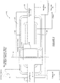
Figure 2 is a simplified block diagram of an inductive sensing system in accordance with the present teachings that may be incorporated into the brake boost assist system shown inFigure 1a to sense the pedal gap in real time, the inductive sensing system having first and second coils which are used to form a variable coupling transformer that provides an electrical signal indicative of the degree of pedal gap present, the coils shown aligned to indicate that no pedal gap is present; -
Figure 3 is shows the inductive sensing system ofFigure 2 but instead showing the first and second coils misaligned to indicate that a pedal gap exists; -
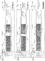
Figure 4 shows another inductive sensing system in accordance with the present teachings for sensing the pedal gap, the induction sensing system using an LC oscillator circuit and a plurality of metallic elements mounted on an output member with a gap between them, and a rectangular metallic member fixedly mounted on the input rod of the brake boost assist system; -
Figure 5 shows the inductive sensing system ofFigure 4 but with the input member partially extended toward the output member, which causes a change in frequency of the LC oscillator circuit of the system, and thus indicates a change in the pedal gap distance; -
Figure 6 shows the inductive sensing system ofFigure 4 but with the input member fully extended over the output member, which results in a maximum change in frequency of the signal generated by the LC oscillator circuit; -
Figure 7 shows one example of how the inductive sensing ofFigure 4 may be implemented into portions of a brake boost assist system; and -
Figure 8 shows the various components ofFigure 7 integrated into the brake boost assist system. - The following description is merely exemplary in nature and is not intended to limit the present disclosure, application, or uses. It should be understood that throughout the drawings, corresponding reference numerals indicate like or corresponding parts and features.
- Referring to
Figure 2 , one embodiment of asystem 10 is shown for inductively sensing a pedal gap between aninput rod 12 and anoutput rod 14 of the boost assist system of the master cylinder assembly shown inFigures 1a-1c . It will be understood that the master cylinder assembly ofFigures 1a-1c is exemplary insofar as the present teachings are concerned. In this regard, the present teachings may be adapted to other master cylinder assemblies within the scope of the present teachings. In this particular implementation, theinput rod 12 is coupled to aninput member 16 that moves with, and parallel to, theinput rod 12. Theoutput rod 14 is likewise coupled to anoutput member 18 that moves with, and parallel to, theoutput rod 14. In the embodiment illustrated, the input member is an axiallymovable input member 16. The coupling may be accomplished with any suitable brackets or other like elements that enable the input andoutput members input rod 12 andoutput rod 14, but spaced slightly radially apart from an axial centerline of the input and output rods, and moved freely axially along with movement of the input andoutput rods - A
housing 20 of the boost assistsystem 10 has an inner surface on which a first coil or first fixedly mountedcoil 22 and a second coil or second fixedly mountedcoil 24 are both fixedly secured. As illustrated, thesecond coil 24 may be disposed within an area circumscribed by thefirst coil 22. The first and second fixedly mountedcoils system 10. One of the first andsecond coils first coil 22 may be coupled to anAC input source 26 and may receive an AC input signal. The secondfixed coil 24 provides its output to acontroller 28. As will be understood by those skilled in the art, the output may be an analog AC output which is first processed by an A/D converter prior to transmission to thecontroller 28. The output represents the signal coupled from thefirst coil 22 to thesecond coil 24, which is directly proportional to a distance of the pedal gap described inFigures 1a-1c , as will be described in greater detail in the following paragraphs. Thecontroller 28, which may be an electronic control unit (ECU) of a vehicle, uses the output signal from thesecond coil 24 to take the pedal gap distance into account. Using this information, along with information from the pedal stroke sensor, enables thecontroller 28 to even more accurately estimate the braking force that needs to be generated in response to the brake pedal movement. - One central feature of the
system 10 of the present teachings is its ability to inductively sense the pedal gap distance at any given time, and help to provide the output signal to the second fixedcoil 24 which takes this pedal gap distance into account. This is accomplished by providing aninput member coil 30 which is secured to, or otherwise mounted on or carried by, theinput member 16, and anoutput member coil 32 which is secured to or otherwise mounted on or carried by theoutput member 18. It will be understood that theinput member coil 30 andoutput member coil 32 may include one or more distinct coil portions. Theinput member 16 andoutput member 18 may be further arranged so that theinput member coil 30 overlaps theoutput member coil 32. InFigure 2 , theinput member 16 is shown on top of theoutput member 18. It will be understood, however, that this configuration may be reversed. One important consideration is that theinput member coil 30 and theoutput member coil 32 are positioned to overlap one another, and further such that theinput member coil 30 and output member coil move axially along a common longitudinal axis. - The
output member 18 and theinput member 16 are further coupled to theoutput rod 14 and theinput rod 12 during construction of the boost assistsystem 10. In this way, when the pedal gap distance is essentially zero, the portions of theinput member coil 30 and theoutput member coil 32 will be perfectly, or essentially perfectly, aligned over one another, as indicated by dashedline 34 inFigure 2 . - In operation, when a pedal gap exists, such as shown in
Figure 3 , the inductive coupling (i.e., magnetic flux coupling) between thefirst coil 22 and thesecond coil 24 will be less than a predetermined maximum value. This is because of the misalignment of theinput member coil 30 and theoutput member coil 32. This misalignment reduces the magnetic flux that can be coupled by theinput member coil 30 and theoutput member coil 32, acting together, from the first fixedcoil 22 to the second fixedcoil 24. The degree or distance of longitudinal spacing between theinput member coil 30 and the output member coil 32 (i.e., axial misalignment) will directly affect the coupling, and the signal coupled into the second fixedcoil 24. The degree or distance of longitudinal spacing may directly affect the coupling in a linear manner. Therefore, when theinput member coil 30 andoutput member coil 32 are misaligned by a maximum axial amount, as indicated inFigure 3 , the signal coupled into the second fixedcoil 24 will be a minimum, but when theinput member coil 30 and theoutput member coil 32 are overlapping as shown inFigure 2 , the maximum magnetic flux will be coupled between the fixed coils 22 and 24, and the signal will be a maximum. In this manner, the input and output member coils 30 and 32 simulate an axial pedal gap separating faces of the input andoutput rods second coil 24 may vary linearly between the minimum and maximum valves directly in accordance with the magnitude of the pedal gap distance. - One important advantage of the
system 10 is that the sensing of the pedal gap distance is not affected by the exact axial location of the pedal gap relative to thehousing 20. In other words, if the pedal gap was present slightly to the left or right in the drawing ofFigure 3 , this orientation would have no effect on the accuracy of thesystem 10 in generating an electrical signal representing the pedal gap distance. As long as theinput member coil 30 andoutput member coil 32 are positioned over both of the first andsecond coils system 10, the system will be able to reliably detect the pedal gap distance. - Referring now to
Figure 4 , asystem 100 in accordance with another embodiment of the present disclosure is shown. Thesystem 100 is similarly operative to sense the pedal gap distance using an inductive sensing methodology. To the extent not otherwise described, it will be understood that features between the twosystems system 100 more specifically uses an LC oscillator-like construction, and senses a change in frequency of an AC signal which is applied to a coil associated with one of the input or output members, which can be correlated proportional to the pedal gap distance. - In
Figure 4 , thesystem 100 can be seen to include aninput member 102 which is operatively coupled to the input rod of the master cylinder ofFigure 1 (not shown inFigure 4 ). Thesystem 100 also includes anoutput member 104 which is operatively coupled to the output rod (also not shown inFigure 4 ). The input andoutput members output members system 10 inFigures 2 and3 . In thesystem 100 ofFigure 4 , theinput member 102 lies over theoutput member 104, but the opposite orientation would work just as well (i.e., theoutput member 104 lies over the input member 102). Both of the input andoutput members coil 108 that is fixedly mounted on an inner wall surface of ahousing 106 of the master cylinder. Thecoil 108 receives an AC signal from anLC oscillator circuit 110. In this example two additional fixedmetallic elements region 116 therebetween. The fixedmetallic elements metallic elements input member 102 includes ametallic member 118, which may be understood as a "first sensing device". Themetallic member 118 preferably has a rectangular shape, and which is fixedly secured to theinput member 102 so that it moves with the input member. Themetallic member 118 may be a thin film of conductive material, such as copper. It will be understood that for certain applications while the rectangular shape may be preferred, other shapes such as a square shape, an oval shape, an elliptical shape, etc. could also be used. A rectangular shape, however, is expected to enhance the frequency change detected by theLC oscillator circuit 110 as themetallic member 118 moves between the positions shown inFigures 4 and 6 , and thereby may enhance the sensing resolution of thesystem 100. - The
metallic member 118 has been described as being secured to theinput member 102 and themetallic elements output member 104. It will also be appreciated, however, that this convention could be reversed. In this regard, themetallic member 118 may be secured to theoutput member 104 and themetallic elements input member 102. The only requirement is that themetallic member 118 and themetallic elements output members metallic member 118 will always be circumscribed by thecoil 108, and will always be moving back and forth relative to thegap 116. - During operation, when the
metallic member 118 is in the position shown inFigure 4 , the degree of metallic material exposed to thecoil 108 will be at a minimum. This amount of material that thecoil 108 "sees" is represented by the shadedportions 120, and is essentially just the metallic material represented by the fixedmetallic elements coil 108. The frequency of the AC signal measured at the output of theLC oscillator circuit 110 will thus be at a predetermined frequency. - As the position of the
input member 102 moves toward theoutput member 104, the tip portion of the rectangular shapedmetallic member 118 will begin to cover thegap 116, as shown inFigure 5 . Thus, thecoil 108 will "see" a greater degree of metallic material. Essentially, the metallic material of the rectangular shapedmetallic member 118 will begin to fill thegap 116, which reduces the inductance of thecoil 108. The inductance is reduced as more metal is presented to thecoil 108. This is because of currents which are induced in the metal (components coil 108. The degree of metallic material "seen" by thecoil 108 is represented by shadedportions 120 inFigure 5 . This causes the frequency of the oscillating signal at the output of theLC oscillator circuit 110 to change. In this respect thesystem 100 operates similar to a conventional metal detector. The degree of change in the frequency of the AC input signal applied to theLC oscillator circuit 110, as measured at its output, can be correlated to the degree of axial movement of theinput member 102 relative to theoutput member 104. This change in frequency indicates whether thegap 116 is effectively converging or lengthening. - In
Figure 6 , theinput member 102 is shown at one extreme position where the rectangular shapedmetallic member 118 is completely bridging the fixedmetallic elements coil 108 "sees" the maximum amount of metallic material. This is represented by the shadedarea 120. The change in frequency of the oscillating output signal from theLC oscillator circuit 110 will be at a maximum. - The
system 100 is able to detect a change in the pedal gap distance by the change in relative position between theinput member 102 and themetallic elements output member 104. Importantly, this change may be detected in real time and may be used by the ECU of the vehicle to even more accurately estimate the pedal stroke travel, and thus to more accurately control the brake boost assist system, working in connection with the master cylinder, to determine the braking pressure being requested by the operator (via brake pedal movement) during a braking operation. - With brief reference to
Figure 7 , asubsystem 200 of the brake boost assist system ofFigure 1c is shown with thesystem 100 ofFigure 4 integrated into it. This represents just one of a plurality of different ways that thesystem 100 can be physically integrated into an otherwise well-known brake boost assist system. Theinput member 102 has one end which forms a sleeve portion 102a which is wrapped around and fixedly coupled to anelongated input rod 206, and anothersleeve portion 102b at its opposite end. Asleeve portion 104b associated with theoutput member 104 is able to slide over the sleeve portion 102a of theinput member 102 and also slide over theelongated input rod 206. Sleeve portion 104a, associated with theoutput member 104, is fixedly secured to theelongated output rod 202.Elongated output rod 202 is also operably associated with alead screw portion 204 of thesubsystem 200, and moves axially along arrow "A" when a threaded lead screw collar (not shown) positioned over thelead screw portion 204 is driven rotationally by an electric motor (not shown) of the brake boost assist system. Theoutput member 104 thus moves axially in accordance with arrow A, and in accordance with movement of theelongated output rod 202 and thelead screw portion 204. And since thesleeve portion 102b of theinput member 102 is uncoupled from sleeve portion 104a, the sleeve portion 102a is able to slide over the sleeve portion 104a and also over theelongated output rod 202, as theelongated input rod 206 and theelongated output rod 202 move relative to one another. - The
elongated input rod 206 is in turn fixedly coupled to abracket arm 208, which is in turn fixedly coupled to aninput member 210 of the brake boost assist system. Therefore, asinput member 210 moves theelongated input rod 206 axially back and forth along arrow A, the sleeve portion 102a, and thus theinput member 102, moves in accordance with it. And since theoutput member 104 has its sleeve portion 104a fixedly secured toelongated output rod 202, theoutput member 104 and its associatedsleeve portion 104b is free to slide over the sleeve portion 102a. - The
input member 102 may have aplanar body portion 102c and theoutput member 104 may have a similarly dimensionedplanar body portion 104c. Theplanar body portions metallic elements Figures 4-6 are positioned on the surface of theoutput member 104planar body portion 104c portion which is substantially hidden from view inFigure 7 . Similarly, themetallic member 118 is positioned on the surface of theplanar body portion 102c of theinput member 102, which is the surface that faces theplanar body portion 104c, and thus is not visible inFigure 7 . Since the overlap of theplanar body portions elongated output rod 202 and sleeve portion 104a) or the input rod 210 (acting in connection with the sleeve portion 102a and elongated input rod 206), the position of themetallic member 118 will change relative to the positions of themetallic elements Figure 7 , it will be appreciated that thecoil 108 is mounted on an interior wall of thehousing 106 of the brake boost assist system as described in connection with the discussion ofFigures 4-6 .Figure 8 shows the various components described above integrated into thesubsystem 200. - It will be understood that both of the
systems Figure 1b or the pedal gap defined inFigure 1c . - The various embodiments of the present disclosure presented herein can be implemented with a limited number of additional component parts, and without significantly increasing the complexity, cost or weight of a master cylinder system of the vehicle. The various embodiments are expected to significantly enhance the accuracy of the determination of the brake pedal stroke.
Claims (18)
- A brake boost assist system (10) for use with a master cylinder of a motor vehicle braking system, the brake boost assist system comprising:
an inductive sensing system including:a fixed sensing component (22,24) fixedly disposed within the brake boost assist system;an axially movable input member (16) operably associated with an input rod (12), the input rod in turn associated with a brake pedal of the vehicle, the input member movable in response to movement of the input rod and further being movable in proximity to the fixed sensing component, the axially movable input member including a first sensing device (30);an output member (18) generally axially aligned with the input member and adapted to be moved axially by the input member, the output member being operably associated with an output rod of the brake boost assist system and including a second sensing device (32);the first and second sensing devices arranged to simulate an axial pedal gap separating faces of the input and output rods; andwherein the inductive sensing system is responsive to movement of at least one of the input and output members relative to the other to provide an output signal indicative of a distance representing the axial pedal gap during brake pedal travel. - The system of claim 1, wherein the first sensing device includes an input member coil carried by the input member.
- The system of claim 2, wherein the second sensing device includes an output member coil carried by the output member.
- The system of claim 1, wherein the fixed sensing component includes first and second coils fixedly mounted within the brake boost assist system, the first coil circumscribing the second coil.
- The system of claim 4, wherein the first and second coils are mounted on an interior wall portion of a housing of the brake boost assist system.
- The system of claim 1, wherein the first sensing device and the second sensing device are further arranged on the input member and the output member, respectively, to overlap during a portion of axial movement of one of the input and output members relative to the other.
- The system of claim 6, wherein the first sensing device includes an input member coil and the second sensing device includes an output member coil, and further wherein the fixed sensing component includes first and second fixedly mounted coils fixedly mounted within the brake boost assist system, the first fixedly mounted coil circumscribing the second fixedly mounted coil; and
wherein a degree of overlap of the input member coil and the output member coil controls a degree of magnetic flux coupling between the first and second fixedly mounted coils to provide the output signal which indicates the distance representing the axial pedal gap. - The system of claim 1, wherein one of the first and second sensing devices comprises a metallic member secured to one of the input member or the output member, and wherein the fixed sensing component comprises a coil fixedly secured to an inner wall of a housing of the brake boost assist system.
- The system of claim 8, wherein a second one of the first and second sensing devices comprises a pair of metallic elements secured to the other one of the input member and the output member, and wherein the pair of metallic elements defines a fixed gap therebetween, and wherein the metallic member is longitudinally aligned with the pair of metallic elements in a manner to be able to at least partially overlay the gap between the pair of metallic elements as the input member is moved relative to the output member.
- The system of claim 9, further comprising an inductive capacitive (LC) circuit for applying an alternating current signal to the coil.
- The system of claim 10, wherein a change in a position of the metallic member, relative to the pair of metallic elements causes a change in a frequency of an output signal from the LC circuit representative of a change in the distance representing the axial pedal gap.
- The system of claim 11, wherein the metallic member overlaps a greater degree or a lesser degree of the gap during movement of the input member relative to the output member, which affects the frequency of the output signal from the LC circuit.
- The system of claim 8, wherein the metallic member comprises a rectangular shaped metallic member.
- A brake boost assist system for use with a master cylinder of a motor vehicle braking system, the brake boost assist system comprising:an inductive sensing system for detecting an axial pedal gap between faces of an input rod (16) and an output rod (18) of the brake boost assist system, the inductive sensing system including:an AC input signal source for generating an AC input signal;a first fixedly mounted coil (22) disposed within the brake boost assist system;a second fixedly mounted coil (24) disposed within the brake boost assist system and circumscribed by the first fixedly mounted coil, one of the first and second fixedly mounted coils receiving the AC input signal;an axially movable input member operably associated with the input rod, which is in turn associated with a brake pedal of the vehicle, and wherein the input member is movable in response to movement of the input rod and further being movable in proximity to the first and second fixedly mounted coils, the axially movable input member including an input member coil (30);an output member generally axially aligned with the input member and adapted to be moved axially by the input member, the output member being operably associated with the output rod of the brake boost assist system and including an input member coil (32);the input and output member coils further being arranged to at least partially overlap one another during movement of the input and output rods;a degree of overlap of the input and output member coils during movement of at least one of the input and output rods influencing an inductive coupling between the first fixedly mounted coil and the second fixedly mounted coil; andthe one of the first and second fixedly mounted coils that is not receiving the AC input signal providing an output signal representing the axial pedal gap during brake pedal travel.
- The system of claim 14, wherein the first and second fixedly mounted coils are mounted to an inner wall of a housing of the brake boost assist system.
- A brake boost assist system for use with a master cylinder of a motor vehicle braking system, the brake boost assist system comprising:
an inductive sensing system for detecting an axial pedal gap between faces of an input rod and an output rod of the brake boost assist system, the inductive sensing system including:an LC oscillator circuit;a coil fixedly disposed within the brake boost assist system which receives an AC signal from the LC oscillator circuit;an axially movable input member operably associated with the input rod, which is in turn associated with a brake pedal of the vehicle, and wherein the input member is movable in response to movement of the input rod and further being movable in proximity to the coil;an output member generally axially aligned with the input member and adapted to be moved axially by the input member, the output member being operably associated with an output rod of the brake boost assist system;one of the input and output members including a metallic sensing member and the other including spaced apart, fixed metallic sensing elements;the metallic sensing member and the metallic sensing elements further being arranged to simulate the axial pedal gap separating the faces of the input and output rods; andthe inductive sensing system being responsive to movement of at least one of the input member and the output member relative to the other, which changes a degree of overlap of the metallic sensing member relative to the metallic sensing elements, which causes a change in frequency of an output signal from the LC oscillator circuit, the output signal being indicative of a distance representing the axial pedal gap during brake pedal travel. - The system of claim 16, wherein the metallic sensing elements comprise a pair of spaced apart, fixed metallic elements arranged along a longitudinal axis of movement of the metallic sensing member, the spaced apart, fixed metallic sensing elements defining a gap therebetween.
- The system of claim 17, wherein the metallic sensing member is arranged to at least partially overlap the gap between the pair of spaced apart, fixed metallic sensing elements during movement of one of the input or output members.
Applications Claiming Priority (2)
| Application Number | Priority Date | Filing Date | Title |
|---|---|---|---|
| US15/639,385 US10239506B2 (en) | 2017-06-30 | 2017-06-30 | System and method for sensing pedal rod to piston rod gap in a brake boost assist system of a master cylinder |
| PCT/US2018/039282 WO2019005669A1 (en) | 2017-06-30 | 2018-06-25 | System and method for sensing pedal rod to piston rod gap in a brake boost assist system of a master cylinder |
Publications (3)
| Publication Number | Publication Date |
|---|---|
| EP3645352A1 EP3645352A1 (en) | 2020-05-06 |
| EP3645352A4 EP3645352A4 (en) | 2021-04-07 |
| EP3645352B1 true EP3645352B1 (en) | 2022-05-11 |
Family
ID=64734615
Family Applications (1)
| Application Number | Title | Priority Date | Filing Date |
|---|---|---|---|
| EP18825288.6A Not-in-force EP3645352B1 (en) | 2017-06-30 | 2018-06-25 | System and method for sensing pedal rod to piston rod gap in a brake boost assist system of a master cylinder |
Country Status (4)
| Country | Link |
|---|---|
| US (1) | US10239506B2 (en) |
| EP (1) | EP3645352B1 (en) |
| CN (1) | CN110799390B (en) |
| WO (1) | WO2019005669A1 (en) |
Families Citing this family (3)
| Publication number | Priority date | Publication date | Assignee | Title |
|---|---|---|---|---|
| DE102019210269A1 (en) * | 2019-07-11 | 2021-01-14 | Robert Bosch Gmbh | Detection method and sensor device for an electromechanical brake booster of a vehicle's own hydraulic brake system |
| CN110466486A (en) * | 2019-08-30 | 2019-11-19 | 爱驰汽车有限公司 | Service brake control method, system, equipment and storage medium |
| DE102022205435A1 (en) * | 2022-05-30 | 2023-11-30 | Robert Bosch Gesellschaft mit beschränkter Haftung | Actuating device for a braking system |
Family Cites Families (11)
| Publication number | Priority date | Publication date | Assignee | Title |
|---|---|---|---|---|
| FR2647741B1 (en) | 1989-05-31 | 1991-08-23 | Bendix France | METHOD FOR ADJUSTING THE JUMP VALUE OF A BRAKE ASSIST MOTOR |
| DE19936433A1 (en) | 1999-07-30 | 2001-02-01 | Continental Teves Ag & Co Ohg | Electric brake booster has electromagnetic element driven by output of transducer for detecting driver's braking force to produce mechanical pulse force transferred to actuating element |
| FR2814233B1 (en) * | 2000-09-15 | 2002-11-15 | Bosch Gmbh Robert | SENSOR MODULE INTEGRATING THE MEASUREMENT OF THE RACE OF A ROD AS WELL AS THE MEASUREMENT OF THE EFFORT EXERCISED ON SAID ROD |
| DE10316838B3 (en) * | 2003-04-11 | 2004-05-06 | Lucas Automotive Gmbh | Piston unit esp. for pedal simulation device for motor vehicle brake systems has flexible sealing ring with overdimension engaging on inner cylinder wall and distorting to permit fluid connection |
| DE102005037792B3 (en) * | 2005-08-10 | 2007-05-31 | Lucas Automotive Gmbh | Master brake cylinder arrangement for a hydraulic motor vehicle brake system and motor vehicle brake system |
| DE102008017852A1 (en) * | 2008-04-09 | 2009-10-15 | Wabco Gmbh | Shift Solenoid |
| US8240780B1 (en) * | 2008-11-26 | 2012-08-14 | Robert Bosch Gmbh | Hydraulic brake booster |
| CN103802814B (en) * | 2012-11-13 | 2017-05-31 | 博世汽车部件(苏州)有限公司 | Brake booster |
| KR101500303B1 (en) * | 2013-07-25 | 2015-03-18 | 주식회사 만도 | Electronic brake apparatus and control method thereof |
| DE102014211008A1 (en) * | 2014-06-10 | 2015-12-17 | Robert Bosch Gmbh | Sensor device and method for carrying out or enhancing an autonomous brake pressure build-up in a brake system by means of an active brake booster |
| KR20170031397A (en) * | 2015-09-11 | 2017-03-21 | 주식회사 만도 | Electric brake system |
-
2017
- 2017-06-30 US US15/639,385 patent/US10239506B2/en active Active
-
2018
- 2018-06-25 EP EP18825288.6A patent/EP3645352B1/en not_active Not-in-force
- 2018-06-25 CN CN201880043080.5A patent/CN110799390B/en active Active
- 2018-06-25 WO PCT/US2018/039282 patent/WO2019005669A1/en not_active Ceased
Also Published As
| Publication number | Publication date |
|---|---|
| US10239506B2 (en) | 2019-03-26 |
| EP3645352A4 (en) | 2021-04-07 |
| EP3645352A1 (en) | 2020-05-06 |
| CN110799390A (en) | 2020-02-14 |
| US20190001940A1 (en) | 2019-01-03 |
| WO2019005669A1 (en) | 2019-01-03 |
| CN110799390B (en) | 2022-03-08 |
Similar Documents
| Publication | Publication Date | Title |
|---|---|---|
| EP3645352B1 (en) | System and method for sensing pedal rod to piston rod gap in a brake boost assist system of a master cylinder | |
| US20090320579A1 (en) | Method and device for measuring an effective normal force on a disk brake | |
| US20190232928A1 (en) | Sensor unit | |
| US8324890B2 (en) | Clutch position sensor for vehicle transmission | |
| US10247578B2 (en) | Path measurement method for a magnetic sensor and sensor | |
| CN102958766B (en) | For the sensor device of pedal with for providing the method for the information about controlled pedal | |
| US11560127B2 (en) | Device for a brake pedal force-travel emulator with force and displacement sensor and corresponding process | |
| CN103534491B (en) | Piston-cylinder-unit with displacement measuring sensor | |
| CN106364472A (en) | A hydraulic block for a hydraulic unit of a brake control unit | |
| KR20200127502A (en) | Stroke sensor device for brake pedal | |
| US20190072146A1 (en) | Disk brake, in particular for commercial vehicles | |
| KR102160324B1 (en) | Method for producing a sensing device | |
| CA2347271C (en) | Control apparatus | |
| CN117048689A (en) | Steering columns for motor vehicles | |
| US6871916B2 (en) | Sensor module integrating both the measurement of a rod travel and measurement of the force exerted on said rod | |
| US20080164886A1 (en) | Inductive Sensor Device Having A Conical Coil Core | |
| GB2108678A (en) | Shock absorber or ram position sensing system | |
| CN120116898A (en) | Inductive measuring assembly and pedal assembly for a vehicle | |
| DE102013220755A1 (en) | Sensor arrangement for detecting a pedal movement in a vehicle | |
| EP4722055A1 (en) | Pedal pad device for a motor vehicle and motor vehicle | |
| DE102015204052A1 (en) | displacement sensor | |
| KR20220040802A (en) | Displacement sensing device of brake pedal | |
| KR102845402B1 (en) | Electric brake device | |
| KR101001186B1 (en) | Automotive inductance braking sensor and signal processing method | |
| JPH06241261A (en) | Detecting method of position of adjustment and stroke measuring device for executing said method |
Legal Events
| Date | Code | Title | Description |
|---|---|---|---|
| STAA | Information on the status of an ep patent application or granted ep patent |
Free format text: STATUS: THE INTERNATIONAL PUBLICATION HAS BEEN MADE |
|
| PUAI | Public reference made under article 153(3) epc to a published international application that has entered the european phase |
Free format text: ORIGINAL CODE: 0009012 |
|
| STAA | Information on the status of an ep patent application or granted ep patent |
Free format text: STATUS: REQUEST FOR EXAMINATION WAS MADE |
|
| 17P | Request for examination filed |
Effective date: 20191203 |
|
| AK | Designated contracting states |
Kind code of ref document: A1 Designated state(s): AL AT BE BG CH CY CZ DE DK EE ES FI FR GB GR HR HU IE IS IT LI LT LU LV MC MK MT NL NO PL PT RO RS SE SI SK SM TR |
|
| AX | Request for extension of the european patent |
Extension state: BA ME |
|
| DAV | Request for validation of the european patent (deleted) | ||
| DAX | Request for extension of the european patent (deleted) | ||
| RAP1 | Party data changed (applicant data changed or rights of an application transferred) |
Owner name: ZF ACTIVE SAFETY US INC. Owner name: VEONEER NISSIN BRAKE SYSTEMS JAPAN CO. LTD. |
|
| A4 | Supplementary search report drawn up and despatched |
Effective date: 20210305 |
|
| RIC1 | Information provided on ipc code assigned before grant |
Ipc: B60T 11/18 20060101ALI20210301BHEP Ipc: B60T 8/171 20060101AFI20210301BHEP Ipc: B60T 13/74 20060101ALI20210301BHEP Ipc: B60T 7/04 20060101ALI20210301BHEP Ipc: B60T 13/573 20060101ALI20210301BHEP Ipc: B60T 8/40 20060101ALI20210301BHEP |
|
| RIC1 | Information provided on ipc code assigned before grant |
Ipc: B60T 13/573 20060101ALI20211018BHEP Ipc: B60T 8/40 20060101ALI20211018BHEP Ipc: B60T 11/18 20060101ALI20211018BHEP Ipc: B60T 13/74 20060101ALI20211018BHEP Ipc: B60T 7/04 20060101ALI20211018BHEP Ipc: B60T 8/171 20060101AFI20211018BHEP |
|
| GRAP | Despatch of communication of intention to grant a patent |
Free format text: ORIGINAL CODE: EPIDOSNIGR1 |
|
| STAA | Information on the status of an ep patent application or granted ep patent |
Free format text: STATUS: GRANT OF PATENT IS INTENDED |
|
| INTG | Intention to grant announced |
Effective date: 20211201 |
|
| GRAS | Grant fee paid |
Free format text: ORIGINAL CODE: EPIDOSNIGR3 |
|
| GRAA | (expected) grant |
Free format text: ORIGINAL CODE: 0009210 |
|
| STAA | Information on the status of an ep patent application or granted ep patent |
Free format text: STATUS: THE PATENT HAS BEEN GRANTED |
|
| AK | Designated contracting states |
Kind code of ref document: B1 Designated state(s): AL AT BE BG CH CY CZ DE DK EE ES FI FR GB GR HR HU IE IS IT LI LT LU LV MC MK MT NL NO PL PT RO RS SE SI SK SM TR |
|
| REG | Reference to a national code |
Ref country code: GB Ref legal event code: FG4D |
|
| REG | Reference to a national code |
Ref country code: CH Ref legal event code: EP |
|
| REG | Reference to a national code |
Ref country code: AT Ref legal event code: REF Ref document number: 1491171 Country of ref document: AT Kind code of ref document: T Effective date: 20220515 |
|
| REG | Reference to a national code |
Ref country code: DE Ref legal event code: R096 Ref document number: 602018035566 Country of ref document: DE |
|
| REG | Reference to a national code |
Ref country code: IE Ref legal event code: FG4D |
|
| REG | Reference to a national code |
Ref country code: LT Ref legal event code: MG9D |
|
| REG | Reference to a national code |
Ref country code: NL Ref legal event code: MP Effective date: 20220511 |
|
| REG | Reference to a national code |
Ref country code: AT Ref legal event code: MK05 Ref document number: 1491171 Country of ref document: AT Kind code of ref document: T Effective date: 20220511 |
|
| PG25 | Lapsed in a contracting state [announced via postgrant information from national office to epo] |
Ref country code: SE Free format text: LAPSE BECAUSE OF FAILURE TO SUBMIT A TRANSLATION OF THE DESCRIPTION OR TO PAY THE FEE WITHIN THE PRESCRIBED TIME-LIMIT Effective date: 20220511 Ref country code: PT Free format text: LAPSE BECAUSE OF FAILURE TO SUBMIT A TRANSLATION OF THE DESCRIPTION OR TO PAY THE FEE WITHIN THE PRESCRIBED TIME-LIMIT Effective date: 20220912 Ref country code: NO Free format text: LAPSE BECAUSE OF FAILURE TO SUBMIT A TRANSLATION OF THE DESCRIPTION OR TO PAY THE FEE WITHIN THE PRESCRIBED TIME-LIMIT Effective date: 20220811 Ref country code: NL Free format text: LAPSE BECAUSE OF FAILURE TO SUBMIT A TRANSLATION OF THE DESCRIPTION OR TO PAY THE FEE WITHIN THE PRESCRIBED TIME-LIMIT Effective date: 20220511 Ref country code: LT Free format text: LAPSE BECAUSE OF FAILURE TO SUBMIT A TRANSLATION OF THE DESCRIPTION OR TO PAY THE FEE WITHIN THE PRESCRIBED TIME-LIMIT Effective date: 20220511 Ref country code: HR Free format text: LAPSE BECAUSE OF FAILURE TO SUBMIT A TRANSLATION OF THE DESCRIPTION OR TO PAY THE FEE WITHIN THE PRESCRIBED TIME-LIMIT Effective date: 20220511 Ref country code: GR Free format text: LAPSE BECAUSE OF FAILURE TO SUBMIT A TRANSLATION OF THE DESCRIPTION OR TO PAY THE FEE WITHIN THE PRESCRIBED TIME-LIMIT Effective date: 20220812 Ref country code: FI Free format text: LAPSE BECAUSE OF FAILURE TO SUBMIT A TRANSLATION OF THE DESCRIPTION OR TO PAY THE FEE WITHIN THE PRESCRIBED TIME-LIMIT Effective date: 20220511 Ref country code: ES Free format text: LAPSE BECAUSE OF FAILURE TO SUBMIT A TRANSLATION OF THE DESCRIPTION OR TO PAY THE FEE WITHIN THE PRESCRIBED TIME-LIMIT Effective date: 20220511 Ref country code: BG Free format text: LAPSE BECAUSE OF FAILURE TO SUBMIT A TRANSLATION OF THE DESCRIPTION OR TO PAY THE FEE WITHIN THE PRESCRIBED TIME-LIMIT Effective date: 20220811 Ref country code: AT Free format text: LAPSE BECAUSE OF FAILURE TO SUBMIT A TRANSLATION OF THE DESCRIPTION OR TO PAY THE FEE WITHIN THE PRESCRIBED TIME-LIMIT Effective date: 20220511 |
|
| PG25 | Lapsed in a contracting state [announced via postgrant information from national office to epo] |
Ref country code: RS Free format text: LAPSE BECAUSE OF FAILURE TO SUBMIT A TRANSLATION OF THE DESCRIPTION OR TO PAY THE FEE WITHIN THE PRESCRIBED TIME-LIMIT Effective date: 20220511 Ref country code: PL Free format text: LAPSE BECAUSE OF FAILURE TO SUBMIT A TRANSLATION OF THE DESCRIPTION OR TO PAY THE FEE WITHIN THE PRESCRIBED TIME-LIMIT Effective date: 20220511 Ref country code: LV Free format text: LAPSE BECAUSE OF FAILURE TO SUBMIT A TRANSLATION OF THE DESCRIPTION OR TO PAY THE FEE WITHIN THE PRESCRIBED TIME-LIMIT Effective date: 20220511 Ref country code: IS Free format text: LAPSE BECAUSE OF FAILURE TO SUBMIT A TRANSLATION OF THE DESCRIPTION OR TO PAY THE FEE WITHIN THE PRESCRIBED TIME-LIMIT Effective date: 20220911 |
|
| PG25 | Lapsed in a contracting state [announced via postgrant information from national office to epo] |
Ref country code: SM Free format text: LAPSE BECAUSE OF FAILURE TO SUBMIT A TRANSLATION OF THE DESCRIPTION OR TO PAY THE FEE WITHIN THE PRESCRIBED TIME-LIMIT Effective date: 20220511 Ref country code: SK Free format text: LAPSE BECAUSE OF FAILURE TO SUBMIT A TRANSLATION OF THE DESCRIPTION OR TO PAY THE FEE WITHIN THE PRESCRIBED TIME-LIMIT Effective date: 20220511 Ref country code: RO Free format text: LAPSE BECAUSE OF FAILURE TO SUBMIT A TRANSLATION OF THE DESCRIPTION OR TO PAY THE FEE WITHIN THE PRESCRIBED TIME-LIMIT Effective date: 20220511 Ref country code: EE Free format text: LAPSE BECAUSE OF FAILURE TO SUBMIT A TRANSLATION OF THE DESCRIPTION OR TO PAY THE FEE WITHIN THE PRESCRIBED TIME-LIMIT Effective date: 20220511 Ref country code: DK Free format text: LAPSE BECAUSE OF FAILURE TO SUBMIT A TRANSLATION OF THE DESCRIPTION OR TO PAY THE FEE WITHIN THE PRESCRIBED TIME-LIMIT Effective date: 20220511 Ref country code: CZ Free format text: LAPSE BECAUSE OF FAILURE TO SUBMIT A TRANSLATION OF THE DESCRIPTION OR TO PAY THE FEE WITHIN THE PRESCRIBED TIME-LIMIT Effective date: 20220511 |
|
| REG | Reference to a national code |
Ref country code: CH Ref legal event code: PL |
|
| REG | Reference to a national code |
Ref country code: DE Ref legal event code: R097 Ref document number: 602018035566 Country of ref document: DE |
|
| REG | Reference to a national code |
Ref country code: BE Ref legal event code: MM Effective date: 20220630 |
|
| PG25 | Lapsed in a contracting state [announced via postgrant information from national office to epo] |
Ref country code: MC Free format text: LAPSE BECAUSE OF FAILURE TO SUBMIT A TRANSLATION OF THE DESCRIPTION OR TO PAY THE FEE WITHIN THE PRESCRIBED TIME-LIMIT Effective date: 20220511 |
|
| PLBE | No opposition filed within time limit |
Free format text: ORIGINAL CODE: 0009261 |
|
| STAA | Information on the status of an ep patent application or granted ep patent |
Free format text: STATUS: NO OPPOSITION FILED WITHIN TIME LIMIT |
|
| PG25 | Lapsed in a contracting state [announced via postgrant information from national office to epo] |
Ref country code: AL Free format text: LAPSE BECAUSE OF FAILURE TO SUBMIT A TRANSLATION OF THE DESCRIPTION OR TO PAY THE FEE WITHIN THE PRESCRIBED TIME-LIMIT Effective date: 20220511 |
|
| 26N | No opposition filed |
Effective date: 20230214 |
|
| PG25 | Lapsed in a contracting state [announced via postgrant information from national office to epo] |
Ref country code: LU Free format text: LAPSE BECAUSE OF NON-PAYMENT OF DUE FEES Effective date: 20220625 Ref country code: LI Free format text: LAPSE BECAUSE OF NON-PAYMENT OF DUE FEES Effective date: 20220630 Ref country code: IE Free format text: LAPSE BECAUSE OF NON-PAYMENT OF DUE FEES Effective date: 20220625 Ref country code: CH Free format text: LAPSE BECAUSE OF NON-PAYMENT OF DUE FEES Effective date: 20220630 |
|
| PG25 | Lapsed in a contracting state [announced via postgrant information from national office to epo] |
Ref country code: SI Free format text: LAPSE BECAUSE OF FAILURE TO SUBMIT A TRANSLATION OF THE DESCRIPTION OR TO PAY THE FEE WITHIN THE PRESCRIBED TIME-LIMIT Effective date: 20220511 Ref country code: BE Free format text: LAPSE BECAUSE OF NON-PAYMENT OF DUE FEES Effective date: 20220630 |
|
| P01 | Opt-out of the competence of the unified patent court (upc) registered |
Effective date: 20230530 |
|
| PGFP | Annual fee paid to national office [announced via postgrant information from national office to epo] |
Ref country code: FR Payment date: 20230510 Year of fee payment: 6 |
|
| PGFP | Annual fee paid to national office [announced via postgrant information from national office to epo] |
Ref country code: GB Payment date: 20230504 Year of fee payment: 6 |
|
| PG25 | Lapsed in a contracting state [announced via postgrant information from national office to epo] |
Ref country code: IT Free format text: LAPSE BECAUSE OF FAILURE TO SUBMIT A TRANSLATION OF THE DESCRIPTION OR TO PAY THE FEE WITHIN THE PRESCRIBED TIME-LIMIT Effective date: 20220511 |
|
| PG25 | Lapsed in a contracting state [announced via postgrant information from national office to epo] |
Ref country code: MK Free format text: LAPSE BECAUSE OF FAILURE TO SUBMIT A TRANSLATION OF THE DESCRIPTION OR TO PAY THE FEE WITHIN THE PRESCRIBED TIME-LIMIT Effective date: 20220511 Ref country code: CY Free format text: LAPSE BECAUSE OF FAILURE TO SUBMIT A TRANSLATION OF THE DESCRIPTION OR TO PAY THE FEE WITHIN THE PRESCRIBED TIME-LIMIT Effective date: 20220511 |
|
| PG25 | Lapsed in a contracting state [announced via postgrant information from national office to epo] |
Ref country code: HU Free format text: LAPSE BECAUSE OF FAILURE TO SUBMIT A TRANSLATION OF THE DESCRIPTION OR TO PAY THE FEE WITHIN THE PRESCRIBED TIME-LIMIT; INVALID AB INITIO Effective date: 20180625 |
|
| PGFP | Annual fee paid to national office [announced via postgrant information from national office to epo] |
Ref country code: DE Payment date: 20240328 Year of fee payment: 7 |
|
| PG25 | Lapsed in a contracting state [announced via postgrant information from national office to epo] |
Ref country code: MT Free format text: LAPSE BECAUSE OF FAILURE TO SUBMIT A TRANSLATION OF THE DESCRIPTION OR TO PAY THE FEE WITHIN THE PRESCRIBED TIME-LIMIT Effective date: 20220511 |
|
| PG25 | Lapsed in a contracting state [announced via postgrant information from national office to epo] |
Ref country code: BG Free format text: LAPSE BECAUSE OF FAILURE TO SUBMIT A TRANSLATION OF THE DESCRIPTION OR TO PAY THE FEE WITHIN THE PRESCRIBED TIME-LIMIT Effective date: 20220511 |
|
| PG25 | Lapsed in a contracting state [announced via postgrant information from national office to epo] |
Ref country code: BG Free format text: LAPSE BECAUSE OF FAILURE TO SUBMIT A TRANSLATION OF THE DESCRIPTION OR TO PAY THE FEE WITHIN THE PRESCRIBED TIME-LIMIT Effective date: 20220511 |
|
| GBPC | Gb: european patent ceased through non-payment of renewal fee |
Effective date: 20240625 |
|
| PG25 | Lapsed in a contracting state [announced via postgrant information from national office to epo] |
Ref country code: FR Free format text: LAPSE BECAUSE OF NON-PAYMENT OF DUE FEES Effective date: 20240630 |
|
| PG25 | Lapsed in a contracting state [announced via postgrant information from national office to epo] |
Ref country code: GB Free format text: LAPSE BECAUSE OF NON-PAYMENT OF DUE FEES Effective date: 20240625 |
|
| PG25 | Lapsed in a contracting state [announced via postgrant information from national office to epo] |
Ref country code: TR Free format text: LAPSE BECAUSE OF FAILURE TO SUBMIT A TRANSLATION OF THE DESCRIPTION OR TO PAY THE FEE WITHIN THE PRESCRIBED TIME-LIMIT Effective date: 20220511 |
|
| REG | Reference to a national code |
Ref country code: DE Ref legal event code: R119 Ref document number: 602018035566 Country of ref document: DE |
|
| PG25 | Lapsed in a contracting state [announced via postgrant information from national office to epo] |
Ref country code: DE Free format text: LAPSE BECAUSE OF NON-PAYMENT OF DUE FEES Effective date: 20260101 |