EP3645239B1 - Method of blow molding with a liquid - Google Patents
Method of blow molding with a liquid Download PDFInfo
- Publication number
- EP3645239B1 EP3645239B1 EP18765706.9A EP18765706A EP3645239B1 EP 3645239 B1 EP3645239 B1 EP 3645239B1 EP 18765706 A EP18765706 A EP 18765706A EP 3645239 B1 EP3645239 B1 EP 3645239B1
- Authority
- EP
- European Patent Office
- Prior art keywords
- preform
- fluid
- volume
- container
- pressure source
- Prior art date
- Legal status (The legal status is an assumption and is not a legal conclusion. Google has not performed a legal analysis and makes no representation as to the accuracy of the status listed.)
- Active
Links
Images


Classifications
-
- B—PERFORMING OPERATIONS; TRANSPORTING
- B29—WORKING OF PLASTICS; WORKING OF SUBSTANCES IN A PLASTIC STATE IN GENERAL
- B29C—SHAPING OR JOINING OF PLASTICS; SHAPING OF MATERIAL IN A PLASTIC STATE, NOT OTHERWISE PROVIDED FOR; AFTER-TREATMENT OF THE SHAPED PRODUCTS, e.g. REPAIRING
- B29C49/00—Blow-moulding, i.e. blowing a preform or parison to a desired shape within a mould; Apparatus therefor
- B29C49/42—Component parts, details or accessories; Auxiliary operations
- B29C49/78—Measuring, controlling or regulating
- B29C49/783—Measuring, controlling or regulating blowing pressure
-
- B—PERFORMING OPERATIONS; TRANSPORTING
- B29—WORKING OF PLASTICS; WORKING OF SUBSTANCES IN A PLASTIC STATE IN GENERAL
- B29C—SHAPING OR JOINING OF PLASTICS; SHAPING OF MATERIAL IN A PLASTIC STATE, NOT OTHERWISE PROVIDED FOR; AFTER-TREATMENT OF THE SHAPED PRODUCTS, e.g. REPAIRING
- B29C49/00—Blow-moulding, i.e. blowing a preform or parison to a desired shape within a mould; Apparatus therefor
- B29C49/02—Combined blow-moulding and manufacture of the preform or the parison
- B29C49/06—Injection blow-moulding
-
- B—PERFORMING OPERATIONS; TRANSPORTING
- B29—WORKING OF PLASTICS; WORKING OF SUBSTANCES IN A PLASTIC STATE IN GENERAL
- B29C—SHAPING OR JOINING OF PLASTICS; SHAPING OF MATERIAL IN A PLASTIC STATE, NOT OTHERWISE PROVIDED FOR; AFTER-TREATMENT OF THE SHAPED PRODUCTS, e.g. REPAIRING
- B29C49/00—Blow-moulding, i.e. blowing a preform or parison to a desired shape within a mould; Apparatus therefor
- B29C49/42—Component parts, details or accessories; Auxiliary operations
- B29C49/46—Component parts, details or accessories; Auxiliary operations characterised by using particular environment or blow fluids other than air
-
- B—PERFORMING OPERATIONS; TRANSPORTING
- B29—WORKING OF PLASTICS; WORKING OF SUBSTANCES IN A PLASTIC STATE IN GENERAL
- B29C—SHAPING OR JOINING OF PLASTICS; SHAPING OF MATERIAL IN A PLASTIC STATE, NOT OTHERWISE PROVIDED FOR; AFTER-TREATMENT OF THE SHAPED PRODUCTS, e.g. REPAIRING
- B29C49/00—Blow-moulding, i.e. blowing a preform or parison to a desired shape within a mould; Apparatus therefor
- B29C49/02—Combined blow-moulding and manufacture of the preform or the parison
- B29C2049/023—Combined blow-moulding and manufacture of the preform or the parison using inherent heat of the preform, i.e. 1 step blow moulding
-
- B—PERFORMING OPERATIONS; TRANSPORTING
- B29—WORKING OF PLASTICS; WORKING OF SUBSTANCES IN A PLASTIC STATE IN GENERAL
- B29C—SHAPING OR JOINING OF PLASTICS; SHAPING OF MATERIAL IN A PLASTIC STATE, NOT OTHERWISE PROVIDED FOR; AFTER-TREATMENT OF THE SHAPED PRODUCTS, e.g. REPAIRING
- B29C49/00—Blow-moulding, i.e. blowing a preform or parison to a desired shape within a mould; Apparatus therefor
- B29C49/42—Component parts, details or accessories; Auxiliary operations
- B29C49/46—Component parts, details or accessories; Auxiliary operations characterised by using particular environment or blow fluids other than air
- B29C2049/4602—Blowing fluids
- B29C2049/465—Blowing fluids being incompressible
- B29C2049/4664—Blowing fluids being incompressible staying in the final article
-
- B—PERFORMING OPERATIONS; TRANSPORTING
- B29—WORKING OF PLASTICS; WORKING OF SUBSTANCES IN A PLASTIC STATE IN GENERAL
- B29C—SHAPING OR JOINING OF PLASTICS; SHAPING OF MATERIAL IN A PLASTIC STATE, NOT OTHERWISE PROVIDED FOR; AFTER-TREATMENT OF THE SHAPED PRODUCTS, e.g. REPAIRING
- B29C49/00—Blow-moulding, i.e. blowing a preform or parison to a desired shape within a mould; Apparatus therefor
- B29C49/42—Component parts, details or accessories; Auxiliary operations
- B29C49/78—Measuring, controlling or regulating
- B29C49/786—Temperature
- B29C2049/7867—Temperature of the heating or cooling means
-
- B—PERFORMING OPERATIONS; TRANSPORTING
- B29—WORKING OF PLASTICS; WORKING OF SUBSTANCES IN A PLASTIC STATE IN GENERAL
- B29K—INDEXING SCHEME ASSOCIATED WITH SUBCLASSES B29B, B29C OR B29D, RELATING TO MOULDING MATERIALS OR TO MATERIALS FOR MOULDS, REINFORCEMENTS, FILLERS OR PREFORMED PARTS, e.g. INSERTS
- B29K2067/00—Use of polyesters or derivatives thereof, as moulding material
- B29K2067/003—PET, i.e. poylethylene terephthalate
-
- B—PERFORMING OPERATIONS; TRANSPORTING
- B29—WORKING OF PLASTICS; WORKING OF SUBSTANCES IN A PLASTIC STATE IN GENERAL
- B29L—INDEXING SCHEME ASSOCIATED WITH SUBCLASS B29C, RELATING TO PARTICULAR ARTICLES
- B29L2031/00—Other particular articles
- B29L2031/712—Containers; Packaging elements or accessories, Packages
- B29L2031/7158—Bottles
Definitions
- This disclosure relates to ways to form and fill containers, and particularly to systems and processes that allow for simultaneously forming and filling plastic containers.
- plastic containers including polyolefin and polyester containers
- plastic containers are used to package numerous commodities previously supplied in glass and other types of containers.
- Blow-molded plastic containers have accordingly become commonplace in packaging numerous commodities.
- plastic materials used in forming blow molded containers include various polyolefins and polyesters, such as polypropylene (PP), polyethylene (PE), high density polyethylene (HDPE), and polyethylene terephthalate (PET).
- PP polypropylene
- PE polyethylene
- HDPE high density polyethylene
- PET polyethylene terephthalate
- blow molding of containers and subsequent filling of containers developed as two independent processes often performed by different entities.
- some fillers have moved blow molding in-house, in certain cases blow molding equipment is directly integrated into container filling lines.
- Equipment manufacturers have recognized advantages associated therewith and are providing "integrated" systems that are designed to insure that blow molding equipment and filling equipment are fully synchronized.
- blow molding and filling continue to be two independent, distinct processes.
- significant costs in terms of time and equipment expenditure may be incurred while separately configuring and performing these two processes.
- a preform e.g., a PET preform
- the preform exits an oven at about 140°C.
- the temperature of the preform desirably stays between about 140°C and about 63°C (the phase change/solidification temperature of PET) ensuring the resultant container has the desired aesthetic and functional properties. Accordingly, containers must be formed at or above the phase change/solidification temperature of the material used to form the container.
- the heated preform at its maximum temperature, has a known (or knowable) amount of heat energy available to be distributed during formation of the container during the blow molding operation.
- 0007 US2013/106027 discloses a system for simultaneously forming and filling a container having a mold cavity defining an internal surface and adapted to accept a preform.
- EP3205474 discloses a method for forming and filling a container by monitoring the pressure of liquid injected in the container.
- WO2014/209339 discloses a system and method for hydraulic blow molding a plastic preform into a container.
- the present technology includes systems and processes that relate to blow molding using coincident forming and filling operations, where a rate of container formation is maximized and heat lost from a container preform is minimized.
- a container can be formed and filled by accelerating a pressure source from an initial state to attain a predefined process speed while applying pressure to a volume of fluid.
- the volume of fluid is fluidly coupled to a preform upon attaining the predefined process speed, where the pressure source directs at least a portion of the volume of fluid into the preform and stretches the preform to form the container.
- the resulting container thereby includes at least the portion of the volume of fluid.
- the volume of fluid is then fluidly decoupled from the container.
- the pressure source is decelerated from the predefined process speed toward the initial state once the volume of fluid is fluidly decoupled from the container. At least a portion of the preform can be disposed in a mold and the pressure source can direct at least the portion of the volume of fluid into the preform and stretch the preform to conform to the mold to form the container. A stretch rod can also be used to mechanically stretch the preform.
- the volume of fluid can include a liquid.
- compositions or processes specifically envisions embodiments consisting of, and consisting essentially of, A, B and C, excluding an element D that may be recited in the art, even though element D is not explicitly described as being excluded herein.
- ranges are, unless specified otherwise, inclusive of endpoints and include all distinct values and further divided ranges within the entire range. Thus, for example, a range of "from A to B" or “from about A to about B” is inclusive of A and of B. Disclosure of values and ranges of values for specific parameters (such as amounts, weight percentages, etc.) are not exclusive of other values and ranges of values useful herein. It is envisioned that two or more specific exemplified values for a given parameter may define endpoints for a range of values that may be claimed for the parameter.
- Parameter X is exemplified herein to have value A and also exemplified to have value Z, it is envisioned that Parameter X may have a range of values from about A to about Z.
- disclosure of two or more ranges of values for a parameter (whether such ranges are nested, overlapping or distinct) subsume all possible combination of ranges for the value that might be claimed using endpoints of the disclosed ranges.
- Parameter X is exemplified herein to have values in the range of 1-10, or 2-9, or 3-8, it is also envisioned that Parameter X may have other ranges of values including 1-9, 1-8, 1-3, 1-2, 2-10, 2-8, 2-3, 3-10, 3-9, and so on.
- first, second, third, etc. may be used herein to describe various elements, components, regions, layers and/or sections, these elements, components, regions, layers and/or sections should not be limited by these terms. These terms may be only used to distinguish one element, component, region, layer or section from another region, layer or section. Terms such as “first,” “second,” and other numerical terms when used herein do not imply a sequence or order unless clearly indicated by the context. Thus, a first element, component, region, layer or section discussed below could be termed a second element, component, region, layer or section without departing from the teachings of the example embodiments.
- the present technology relates to various methods and systems that permit the forming and filling of a preform at a rate previously not attainable by conventional methods and systems.
- methods of simultaneously forming and filling a container and systems configured for performing such methods include acceleration of a pressure source from an initial state to attain a predefined process speed while applying pressure to a volume of fluid.
- the volume of fluid is fluidly coupled to a preform upon attaining the predefined process speed, where the pressure source directs at least a portion of the volume of fluid into the preform and stretches the preform to form the container.
- the container resulting therefrom includes at least the portion of the volume of fluid.
- the volume of fluid is fluidly decoupled from the container, whereafter the pressure source is decelerated from the predefined process speed toward the initial state.
- the pressure source is allowed to accelerate to the predefined process speed prior to fluidly coupling the preform to the volume of fluid, where the volume of fluid is then fluidly decoupled from the container prior to deceleration of the pressure source.
- This provides an improvement in fill time, where certain embodiments can reduce the fill time by almost 40%.
- a fill channel to the preform can be vented at a point where motion of the pressure source ceases (e.g., forward travel of a servo pressure system is at a maximum), then the fill circuit can be exhausted.
- the improved sequencing of the fluid coupling and decoupling improves the filling and forming time for blow molding a preform, provides an increase in the rate at which preforms can be processed, does not introduce any process instability, and can make it unnecessary to increase power to the pressure source in order to increase filling and forming speed.
- the pressure source can include various structural and functional aspects.
- the pressure source can have a velocity of about zero at the initial state. That is, the pressure source can start from a resting state, where substantially no pressure is applied to the volume of fluid.
- the pressure source can direct at least the portion of the volume of fluid into the preform at a substantially constant process speed until the volume of fluid is fluidly decoupled from the container.
- This constant process speed can allow for a predetermined stretching rate for a given container and for a predetermined fill volume.
- the substantially constant process speed can be tailored for a particular container having a particular volume and even for a particular mold type or shape.
- the pressure source, and the predefined process speed thereof can form and fill the preform in to the container in certain defined time periods.
- the pressure source directs at least the portion of the volume of fluid into the preform and stretches the preform to form the container in less than about 0.5 seconds, in about 0.03 seconds to about 0.15 seconds, and in less than about 0.1 seconds.
- Various types of pressure sources can be used with the present technology, including a servo pressure system, a piston-like device (actuated by one of pneumatic, mechanical, and hydraulic pressure), and a hydraulic pump.
- Other pressure sources can be used; however, acceleration time of the pressure source can be important to the forming and filling time for a given container and hence rapidly accelerating pressure sources such as a servo pressure system can be particularly useful in certain embodiments.
- the preform can include the various following aspects.
- a least a portion of the preform can be disposed in a mold and the pressure source can direct at least the portion of the volume of fluid into the preform and stretch the preform to conform to the mold. In this way, the container including at least the portion of the volume of fluid is formed and filled.
- the preform can be at or above a phase change/solidification temperature of a material from which the preform is formed. For example, the preform can be heated or preheated to about the melting point of the material from which the preform is made.
- various plastics and polymer types, including blends thereof can be used in blow molding. However, one preferred plastic that can be used in conjunction with the present technology is polyethylene terephthalate.
- the preform can be heated or preheated to a temperature between about 88°C (about 190°F) and about 121°C (about 250°F).
- the preform can also be mechanically stretched with a stretch rod.
- the heated or preheated preform can be mechanically stretched in an axial direction using the stretch rod, where the pressure source directing at least a portion of the volume of fluid into the preform causes stretching of the preform in a radial direction.
- the pressure source can also contribute to axial stretching of the preform in certain embodiments.
- the volume of fluid used to form and fill the container can include various fluids, amounts of fluids, and fluids derived from various process streams. Examples include where the volume of fluid includes a liquid, where the volume of fluid includes a gaseous fluid portion and a liquid fluid portion, or where the volume of fluid is substantially all liquid.
- the fluid can be subject to temperature control and can be the output from various pasteurization or sterilization operations, including various filtration, mixing, and/or gassing or degassing operations.
- Types of fluids include various liquid solutions, suspensions, and emulsions of various food and drink products, cleaners, soaps, detergents, medicines, chemicals, and solvents, to name a few non-limiting examples.
- Fluidly coupling and decoupling the volume of fluid to the preform can include the following aspects.
- fluidly coupling the volume of fluid to the preform includes opening a valve positioned between the preform and the volume of fluid.
- the valve can separate a blow nozzle from the volume of fluid, where the preform is coupled to the blow nozzle.
- Fluidly decoupling the volume of fluid from the container can include closing the valve.
- Stretching the preform to form the container can include providing a hydraulic pressure within the preform of about 100 psi to about 600 psi (about 689 kPa to about 4137 kPa).
- the pressure within the preform can be selected based upon several factors, including the size of the container and/or the speed at which the forming and filling operation is to be completed. It is understood that contact between the preform and the portion of the volume of fluid directed into the preform can in certain embodiments result in heat transfer from the preform to the fluid.
- the forming and filling of the container includes selection of parameters that balance the speed of the forming and filling with the cooling rate of the preform to maximize formation of the container prior to any heat loss presenting an issue with stretching of the preform and integrity of the resulting container.
- the present technology can provide an improvement in forming and fill time for a given blow molding operation.
- Fluidly coupling in a window defined by the attainment of the predefined process speed and prior to deceleration minimizes contact time between the preform and the portion of the fluid directed into the preform, thereby minimizing any heat loss from the preform to the fluid.
- certain embodiments of the present technology can reduce the forming and fill time by almost 40%.
- the present technology can include where a time required to fill and form the container can be less than a time required to form the container by a method including the steps of: accelerating the pressure source from the initial state to attain a predefined process speed while applying pressure to the volume of fluid, the volume of fluid fluidly coupled to the preform, the pressure source directing at least the portion of the volume of fluid into the preform and stretching the preform; and decelerating the pressure source from the predefined process speed toward the initial state, thereby completing a stretching of the preform and forming the container, the container including at least the portion of the volume of fluid.
- Certain embodiments of the present technology include simultaneously forming and filling a container in the following way.
- a pressure source is accelerated from an initial state to attain a predefined process speed while pressure is applied to a volume of fluid, where the volume of fluid includes a liquid.
- the volume of fluid is fluidly coupled to a preform upon attaining the predefined process speed, where the preform is at or above a phase change/solidification temperature of a material from which the preform is formed.
- the preform is disposed in a mold and the pressure source directs at least a portion of the volume of fluid into the preform and stretches the preform to conform to the mold to form the container.
- the resulting container includes at least the portion of the volume of fluid.
- the volume of fluid is then fluidly decoupled from the container.
- the pressure source is then decelerated from the predefined process speed toward the initial state. It is possible to mechanically stretch the preform with a stretch rod prior to fluidly coupling the volume of fluid to a preform upon attaining the predefined process speed.
- the pressure source can be configured as a servo pressure system.
- a mold station 10 is provided that is adapted to utilize a liquid commodity L (e.g., an end product used to form and fill a container) where the liquid imparts the pressure required to expand a heated preform 12 to take on the shape of a mold and thereby simultaneously form and fill the resulting container C.
- L e.g., an end product used to form and fill a container
- the system and method are illustrated with various particular means to perform certain structural and functional aspects of the present technology.
- the mold station 10 can include the following details.
- the mold station 10 generally includes a mold cavity 16, a pressure source 20, such as a high speed servo drive unit, a blow nozzle 22, and an optional stretch rod 26.
- the mold cavity 16 shown in Figures 1-7 includes two mold portions 30, 32 (e.g., mold halves) that cooperate to define an interior surface 34 corresponding to a desired outer profile of a blown container.
- the mold cavity 16 can be moveable between an open position ( Figure 1 ) and a closed position ( Figure 2 ) such that a support ring 38 of the preform 12 is coupled, supported, or immobilized at an upper end of the mold cavity 16.
- the pressure source 20 can be in the form of, but not limited to, a servo drive unit or servo pressure system, a piston-like device (e.g., a piston-like device actuated by any suitable means such as pneumatic, mechanical, and/or hydraulic pressure), a pump (e.g., a hydraulic pump, or the like), or combinations thereof.
- a movable filling cylinder, manifold, or chamber may not provide sufficient space optimization or facility efficiency.
- the pressure source 20 is a servo system 60 that generally includes one or more servo motors 62 being actuated by one or more controllers 64 via a line 66.
- the servo system 60 can be positioned adjacent to the preform shaping location to achieve additional benefits.
- the servo system 60 includes an inlet 46 for accepting liquid commodity L and an outlet 48 for delivering the liquid commodity L to the blow nozzle 22. It is appreciated that the inlet 46 and the outlet 48 each include at least one valve 47, 49, respectively, that facilitate the flow of fluid (including liquid commodity L) through the mold station 10.
- the servo motor 62 may be operable in a first direction to draw the liquid commodity L from a fluid source (not shown) through the inlet 46 and output the liquid commodity L from the outlet 48 to the blow nozzle 22 (e.g., forward flow).
- the servo motor 62 may also be operable in a second direction to draw the liquid commodity L from the outlet 48, the blow nozzle 22, and/or the preform 12 (e.g., reverse flow), which will be discussed in greater detail herein.
- the inlet 46 of the pressure source 20 can be fluidly connected, such as by tubing or piping, to the fluid source (e.g., a reservoir or a container) that contains the liquid commodity L. It is appreciated that the pressure source 20 can be configured differently in various embodiments.
- the servo system 60 and any associated filling cylinder can be located generally adjacent to the blow nozzle 22. For reasons enumerated herein, by minimizing the flow distance, flow rates and pressures can be maximized. In some embodiments, as illustrated, corners or other restrictions can be minimized or eliminated, including corners, bends, and/or constricting fittings. In fact, in some embodiments, the servo system 60 and/or any associated fill cylinder may be mounted directly to the blow nozzle 22.
- this direct mounting configuration is not required as many of the benefits can be achieved by minimizing flow path length and mandrel bends, and maintaining the inside or inner diameters of the flow path as large as possible for the entire distance from the servo system 60 and any associated fill cylinder to the blow nozzle 22.
- the servo system 60 and any associated filling cylinder can be sized to output a volume of the liquid commodity L required to fully form and fill the container C, through a stroke of the servo, which can occur very rapidly (e.g., in less than about 0.2 seconds). It should be understood that servo system 60 can provide flow rates that are variable or selective, and/or operate at variable or selective pressures, within a predetermined amount of time.
- the forming and filling operation can use a high speed servo drive unit matched to a filling cylinder. Ideally, this can be a matched system that can produce pressures of up to about 4137 kPa (600 Psi) while accelerating fast enough to fill a 2 liter container in less than 0.4 seconds with a more desirable fill time of about 0.2 seconds.
- the servo system 60 can be selected to have a desired force capability, can be coupled to an appropriate pitch ball screw, and can be attached to a selected and appropriately sized fill piston cylinder.
- the following configuration has been shown to be acceptable in certain embodiments: a 400 volt, 6 kW servo motor coupled to a 12 mm pitch ball drive screw and a 152,4 mm (6 inch) cylinder.
- the following configuration can be used in some embodiments: a 7.5 kW servo coupled to a 14 mm ball drive and a 139.7 mm (5,5 inch) cylinder. Consequently, it has been found that the present technology can be used to form and fill a 16 oz container and a 64 oz container in approximately the same relative time, that is, in about 0.03 to about 0.4 seconds, depending upon the neck finish size and the final container geometry.
- the servo motor 62 can be used to overcome some of the difficulties in metering precise and/or minute quantities of the liquid commodity L. That is, the servo motor 62 can be precisely and variably controlled to permit precise metering of a throughflow of the commodity L and at a variable rate. This precise and variable control can be coupled with a feedback loop to provide active and real-time monitoring and control of the fill process, including stopping of the filling process in the event of a detected issue, such as a blow-out of the resulting container.
- the feedback loop can be formed as part of the controller 64, with appropriate sensors disposed at any one of a number of locations to provide sufficient data to detect a relevant parameter (e.g., pressure sensors, flow sensors, shape sensors, and the like).
- a relevant parameter e.g., pressure sensors, flow sensors, shape sensors, and the like.
- the blow nozzle 22 generally defines an inlet 50 for accepting the liquid commodity L from the outlet 48 of the pressure source 20 and provides an outlet 56 (see Figure 1 ) for delivering the liquid commodity L into the preform 12. It is appreciated that the outlet 56 may define a shape complementary to the preform 12 near the support ring 38 such that the blow nozzle 22 may easily engage or mate with the preform 12 during the forming/filling process. In embodiments employing a sealing gasket disposed between blow nozzle 22 and preform 12, it should be noted that the sealing gasket can have minimal overlap into the fluid path so it does not hinder the flow of the liquid commodity L into the preform 12.
- the blow nozzle 22 and/or the pressure source 20 may define an opening 58 for slidably accepting the optional stretch rod 26 used to initiate mechanical stretching of the preform 12.
- the stretch rod 26 is not required in all embodiments.
- SRWS Stretch Rod Withdrawal System
- the fluid flow of liquid commodity L can begin to fill and form the preform 12.
- the stretch rod 26 can be simultaneously retracted when the fill sequence is activated thus increasing the available area for fluid flow into the preform 12.
- the stretch rod 26 can be used to first enter the preform to displace air within the preform to facilitate subsequent introduction of the commodity L. To this end, the stretch rod 26 can be simultaneously retracted during introduction of fluid flow to provide an enhanced vacuum pull on fluid introduction. In addition to increasing the fluid path to maximum allowable, this system can also be employed to enter back into the container post fill to accurately set the fill level through a process of volume displacement. Additionally, vents may be formed in the stretch rod 26 to facilitate the venting of air contained within a preform prior to filling.
- the liquid commodity L may be continuously circulated within the pressure source 20 and/or filling chamber through the inlet 46.
- the temperature of the liquid L can be controlled and the liquid L can be heated or cooled, as desired.
- the resulting container C may be suitable for other high-temperature pasteurization or retort filling processes, or other thermal processes as well.
- the liquid commodity L can be introduced into the resulting container C under ambient or cold temperatures.
- the resulting container C can be filled at ambient or cold temperatures such as between approximately 32°F to 90°F (approximately 0°C to 32°C), and more preferably at approximately 40° F (approximately 4.4°C).
- the preform 12 may be placed into the mold cavity 16.
- a machine places the preform 12 heated to a temperature above its phase change/solidification temperature (for PET, between about approximately 190°F and about 250°F, approximately 88°C to 121°C) into the mold cavity 16.
- the mold portions 30, 32 of the mold cavity 16 can then close thereby holding the preform 12 ( Figure 2 ).
- the blow nozzle 22 can form a seal at a finish of the preform 12.
- the mold cavity 16 may be heated to a temperature between approximately 250°F to 350°F (approximately 93°C to 177°C).
- the mold cavity 16 may be provided at ambient or cold temperatures between approximately 32° F to 90° F (approximately 0°C to 32°C).
- the pressure source 20 may begin to draw liquid commodity L into the filling cylinder, manifold, or chamber through the inlet 46. Liquid commodity L may continue to be drawn into the system by the pressure source 20 as the preform 12 is sealed against the blow nozzle and/or as the mold portions 30, 32 close.
- the stretch rod 26 may extend into the preform 12 to initiate mechanical stretching thereof.
- the stretch rod 26 can continue to stretch the preform 12 thereby thinning the sidewalls of the preform 12.
- the stretch rod 26 can be immediately retracted after initial stretching while pressurized fluid flows into the preform 12.
- the volume of liquid commodity L in the filling cylinder, manifold, or chamber may increase until the appropriate volume suitable to form and fill the resulting container C is reached. It should be noted that this can be done at any point in time.
- the liquid commodity L can be imparted into the preform 12 during this stretching phase to prevent the preform from contacting the stretch rod and/or to fill the resultant space with liquid rather than air that is later displaced during filling.
- the liquid commodity L flowing into the mold station 10 flows through a closed fill channel circuit that includes the fluid source (not shown) for providing the fluid commodity L through the inlet 46, to the outlet 48, and into the preform 12. Excess fluid L not used to form the preform 12 or that is removed during the blowing and filling process may be recirculated back to the fluid source.
- a fill channel circuit defined by a portion of the mold station 10 between the valves 47, 49 and including the pressure source 20, is filled with a desired volume of liquid L from the fluid source.
- the fill channel circuit is then isolated by closing the valve 49 and the valve 47.
- the pressure source 20 is allowed to accelerate to a predefined process speed, whereupon the pressure source is allowed to decelerate, after which time the fill channel circuit is reopened to facilitate fluid flow to the preform 12.
- Valve 51 is either open or not present in the mold station 10 during acceleration and deceleration of the pressure source.
- FIG. 8 depicts a graph of velocity of the pressure source 20 versus time, wherein line A represents the acceleration of the pressure source, line B represents the deceleration of the pressure source, line D represents the closing of the valves 47, 49, and line E represents the opening of the valves 47, 49.
- the flow of the liquid commodity L in the station 10 can be modified to optimize the time required for the forming and filling process to result in a more rapid creation of the container C, thereby minimizing heat energy losses from the preform 12.
- the pressure source 20 is allowed to accelerate to the predefined process speed (line A of Figure 8 ) before the fill channel circuit is fluidly coupled to the preform by opening valve 51 (opening of valve 51 is represented by line F in Figure 8 ).
- opening valve 51 opening of valve 51 is represented by line F in Figure 8 .
- a pin valve or other valve within the blow nozzle 22 can be used to control the fluid coupling between the volume of liquid commodity L and the preform 12.
- valve 51, a pin valve, and/or a valve located in the blow nozzle 22 can be opened at line F in Figure 8 , thereby fluidly coupling the volume of fluid (the liquid commodity L) to the preform 12 upon the pressure source 20 (the servo system 60) attaining the predefined process speed.
- This allows the pressure source 20 to direct at least a portion of the volume of fluid (the liquid commodity L) into the preform 12 and stretch the preform 12 to form the container C.
- the valve 51 (or pin valve, and/or valve located in the blow nozzle 22) is then closed prior to deceleration of the pressure source 20 (represented by line G in Figure 8 ). This results in an improvement of the fill time by about 38% as compared to known processes described herein.
- a fill time of the preform 12 can be reduced by up to about 40%, thus reducing the filling time to about 0.05-0.4 seconds or less depending upon the neck finish size and the container geometry.
- the fill channel circuit may be vented when the motion of the pressure source 20 ceases (e.g., when accelerated movement of the pressure source 20 is at a maximum).
- the servo system 60 can be actuated to initiate the rapid transfer of liquid commodity L from the filling cylinder, manifold, or chamber to the preform 12.
- the hydraulic pressure within the preform 12 may reach between approximately 100 PSI to 600 PSI (approximately 689 kPa to 4137 kPa).
- the liquid commodity L causes the preform 12 to expand toward the interior surface 34 of the mold cavity 16. Residual air may be vented through a passage (not shown) defined in the stretch rod 26 ( Figure 5 ).
- the servo system 60 has now completely transferred the appropriate volume of liquid commodity L to the newly formed resulting container C.
- the stretch rod 26 may be withdrawn from the mold cavity 16, if it was not already withdrawn.
- the stretch rod 26 may be designed to displace a predetermined volume of liquid commodity L when it is withdrawn from the mold cavity 16 thereby allowing for the desired fill level of liquid commodity L within the resulting container C and/or the desired headspace.
- the fill cycle is shown completed.
- the mold portions 30, 32 may separate and the blow nozzle 22 may be withdrawn.
- the resulting filled container C is now ready for post-forming steps such as capping, labeling, and packing.
- the servo system 60 may begin the next cycle by drawing liquid commodity L through the inlet 46 of the pressure source 20 in preparation for the next fill/form cycle.
- the mold station 10 may include a controller 64 for communicating signals to the various components. In this way, components such as, but not limited to, the mold cavity 16, the blow nozzle 22, the stretch rod 26, the pressure source 20, and various valves, if employed, may operate according to a signal communicated by the controller. It is also contemplated that the controller may be utilized to adjust various parameters associated with these components according to a given application.
- preforms may be passed through an oven in excess of 212° F (100° C) and immediately filled and capped. In this way, the opportunity for an empty container to be exposed to the environment where it might become contaminated is greatly reduced. As a result, the cost and complexity of aseptic forming and filling may be greatly reduced.
- the package In some instances where products are hot filled, the package must be designed to accommodate the elevated temperature that it is exposed to during filling and the resultant internal vacuum it is exposed to as a result of the product cooling. A design that accommodates such conditions may require added container weight. Liquid/hydraulic blow molding can reduce or eliminate the added material required for hot fill processes, and as a result, lower the package weight.
- the method described herein can be particularly useful for filling applications such as isotonic, juice, tea, and other commodities that are susceptible to biological contamination. As such, these commodities are typically filled in a controlled, sterile environment. Commercially, various ways can be used to achieve the required sterile environment.
- One primary method for filling beverages is by using an aseptic filling environment. The filling operation is performed in a clean room. All of the components of the product including the packaging must be sterilized prior to filling. Once filled, the product may be sealed until it is consumed preventing any potential for the introduction of bacteria.
- bottled products can produced using the present technology.
- Products such as dairy products, liquor, household cleaners, salad dressings, sauces, spreads, syrups, edible oils, personal care items, and others may be bottled utilizing such methods.
- Many of these products are currently in blow molded PET containers but are also in extrusion molded plastic containers, glass bottles, and/or cans.
- the present technology can improve the economics of package manufacture and filling for such products.
- the present technology attains certain benefits and advantages.
- it has been found that combined forming and filling durations of about 0.3 seconds to about 0.2 seconds provide even more improved container quality and manufacturing efficiencies. Structurally, it has been found that this rapid forming and filling process of the present teachings results in improved container structures on a crystalline level.
Landscapes
- Engineering & Computer Science (AREA)
- Manufacturing & Machinery (AREA)
- Mechanical Engineering (AREA)
- Blow-Moulding Or Thermoforming Of Plastics Or The Like (AREA)
Description
- 0001 This disclosure relates to ways to form and fill containers, and particularly to systems and processes that allow for simultaneously forming and filling plastic containers.
- 0002 This section provides background information related to the present disclosure which is not necessarily prior art.
- 0003 As a result of environmental and other concerns, various plastic containers, including polyolefin and polyester containers, are used to package numerous commodities previously supplied in glass and other types of containers. Manufacturers and fillers, as well as consumers, have recognized that plastic containers are lightweight, inexpensive, recyclable, and manufacturable in large quantities. Blow-molded plastic containers have accordingly become commonplace in packaging numerous commodities. Examples of plastic materials used in forming blow molded containers include various polyolefins and polyesters, such as polypropylene (PP), polyethylene (PE), high density polyethylene (HDPE), and polyethylene terephthalate (PET).
- 0004 Traditionally, blow molding of containers and subsequent filling of containers developed as two independent processes often performed by different entities. In order to make bottle filling more cost effective, some fillers have moved blow molding in-house, in certain cases blow molding equipment is directly integrated into container filling lines. Equipment manufacturers have recognized advantages associated therewith and are providing "integrated" systems that are designed to insure that blow molding equipment and filling equipment are fully synchronized. Despite the efforts in bringing the two processes closer together, blow molding and filling continue to be two independent, distinct processes. As a result, significant costs in terms of time and equipment expenditure may be incurred while separately configuring and performing these two processes.
- 0005 One process for simultaneously forming and filling a container is described in
U.S. Pat. No. 8,573,964 , hereby incorporated herein in its entirety by reference. During the process disclosed in the '964 patent, a preform (e.g., a PET preform) is heated prior to entering the blow molding system. The preform exits an oven at about 140°C. During the molding process, the temperature of the preform desirably stays between about 140°C and about 63°C (the phase change/solidification temperature of PET) ensuring the resultant container has the desired aesthetic and functional properties. Accordingly, containers must be formed at or above the phase change/solidification temperature of the material used to form the container. The heated preform, at its maximum temperature, has a known (or knowable) amount of heat energy available to be distributed during formation of the container during the blow molding operation. - 0006 During the blow molding operation, this heat energy is lost to the mold surrounding the preform, lost to the fluid used to expand the heated preform into the container, and the heat energy is also distributed along the larger surface area of the container formed from the stretched and blown preform. Because a portion of the heat energy of the preform is provided in the neck finish, and is thus unavailable for loss or distribution during the blow molding process due to neck finishes not being contacted by the fluid used for the blow molding operation nor disfigured or otherwise affected by the blow molding operation, a smaller portion of the total heat energy is available for distribution to the fill fluid, mold, etc. Accordingly, undesirable heat losses may cause concerns with consistent forming and filling of containers. It would be desirable to develop ways to form containers that maintain thermal properties of a heated preform during an expansion and filling thereof.
- 0007
US2013/106027 discloses a system for simultaneously forming and filling a container having a mold cavity defining an internal surface and adapted to accept a preform.EP3205474 discloses a method for forming and filling a container by monitoring the pressure of liquid injected in the container.WO2014/209339 discloses a system and method for hydraulic blow molding a plastic preform into a container. - 0008 The present technology includes systems and processes that relate to blow molding using coincident forming and filling operations, where a rate of container formation is maximized and heat lost from a container preform is minimized.
- 0009 According to the present invention, there is provided a method of simultaneously forming and filling a container as set out in claim 1. Optional features are presented in dependent claims 2 to 15. A container can be formed and filled by accelerating a pressure source from an initial state to attain a predefined process speed while applying pressure to a volume of fluid. The volume of fluid is fluidly coupled to a preform upon attaining the predefined process speed, where the pressure source directs at least a portion of the volume of fluid into the preform and stretches the preform to form the container. The resulting container thereby includes at least the portion of the volume of fluid. The volume of fluid is then fluidly decoupled from the container. The pressure source is decelerated from the predefined process speed toward the initial state once the volume of fluid is fluidly decoupled from the container. At least a portion of the preform can be disposed in a mold and the pressure source can direct at least the portion of the volume of fluid into the preform and stretch the preform to conform to the mold to form the container. A stretch rod can also be used to mechanically stretch the preform. The volume of fluid can include a liquid.
- 0010 Further areas of applicability will become apparent from the description provided herein. The description and specific examples in this summary are intended for purposes of illustration only and are not intended to limit the scope of the present disclosure as disclosed in the appended claims.
- 0011 The drawings described herein are for illustrative purposes only of selected embodiments.
- 0012
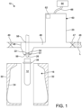
Figure 1 is a schematic depiction of a heated preform passed into a mold station. - 0013
Figure 2 is a schematic depiction of the system illustrated inFigure 1 where two mold portions close around the preform. - 0014
Figure 3 is a schematic depiction of the system illustrated inFigure 2 wherein a stretch rod extends into the preform. - 0015
Figure 4 is a schematic depiction of the system ofFigure 3 wherein the stretch rod mechanically stretches the preform. - 0016
Figure 5 is a schematic depiction of the system ofFigure 4 wherein a pressure source directs a volume of fluid including liquid into the preform thereby expanding the preform toward the walls of the mold cavity. - 0017
Figure 6 is a schematic depiction of the system ofFigure 5 wherein the pressure source has directed an appropriate volume of liquid to the preform, the preform is expanded to conform to the mold and form a container holding the liquid, and the stretch rod is being withdrawn. - 0018
Figure 7 is a schematic depiction of the system ofFigure 6 wherein the two mold portions are separated from the formed and filled container. - 0019
Figure 8 is graph illustrating speed of a pressure source versus time, the pressure source directing at least a portion of a volume of liquid into a preform to form and fill a resulting container. - 0020 Regarding methods disclosed, the order of the steps presented is exemplary in nature, and thus, the order of the steps can be different in various embodiments. "A" and "an" as used herein indicate "at least one" of the item is present; a plurality of such items may be present, when possible. Except where otherwise expressly indicated, all numerical quantities in this description are to be understood as modified by the word "about" and all geometric and spatial descriptors are to be understood as modified by the word "substantially" in describing the broadest scope of the technology. "About" when applied to numerical values indicates that the calculation or the measurement allows some slight imprecision in the value (with some approach to exactness in the value; approximately or reasonably close to the value; nearly). If, for some reason, the imprecision provided by "about" and/or "substantially" is not otherwise understood in the art with this ordinary meaning, then "about" and/or "substantially" as used herein indicates at least variations that may arise from ordinary methods of measuring or using such parameters.
- 0021
- 0022 Although the open-ended term "comprising," as a synonym of non-restrictive terms such as including, containing, or having, is used herein to describe and claim embodiments of the present technology, embodiments may alternatively be described using more limiting terms such as "consisting of" or "consisting essentially of." Thus, for any given embodiment reciting materials, components, or process steps, the present technology also specifically includes embodiments consisting of, or consisting essentially of, such materials, components, or process steps excluding additional materials, components or processes (for consisting of) and excluding additional materials, components or processes affecting the significant properties of the embodiment (for consisting essentially of), even though such additional materials, components or processes are not explicitly recited in this application. For example, recitation of a composition or process reciting elements A, B and C specifically envisions embodiments consisting of, and consisting essentially of, A, B and C, excluding an element D that may be recited in the art, even though element D is not explicitly described as being excluded herein.
- 0023 As referred to herein, disclosures of ranges are, unless specified otherwise, inclusive of endpoints and include all distinct values and further divided ranges within the entire range. Thus, for example, a range of "from A to B" or "from about A to about B" is inclusive of A and of B. Disclosure of values and ranges of values for specific parameters (such as amounts, weight percentages, etc.) are not exclusive of other values and ranges of values useful herein. It is envisioned that two or more specific exemplified values for a given parameter may define endpoints for a range of values that may be claimed for the parameter. For example, if Parameter X is exemplified herein to have value A and also exemplified to have value Z, it is envisioned that Parameter X may have a range of values from about A to about Z. Similarly, it is envisioned that disclosure of two or more ranges of values for a parameter (whether such ranges are nested, overlapping or distinct) subsume all possible combination of ranges for the value that might be claimed using endpoints of the disclosed ranges. For example, if Parameter X is exemplified herein to have values in the range of 1-10, or 2-9, or 3-8, it is also envisioned that Parameter X may have other ranges of values including 1-9, 1-8, 1-3, 1-2, 2-10, 2-8, 2-3, 3-10, 3-9, and so on.
- 0024 The terminology used herein is for the purpose of describing particular example embodiments only and is not intended to be limiting. As used herein, the singular forms "a", "an" and "the" may be intended to include the plural forms as well, unless the context clearly indicates otherwise. The terms "comprises," "comprising," "including," and "having," are inclusive and therefore specify the presence of stated features, integers, steps, operations, elements, and/or components, but do not preclude the presence or addition of one or more other features, integers, steps, operations, elements, components, and/or groups thereof. The method steps, processes, and operations described herein are not to be construed as necessarily requiring their performance in the particular order discussed or illustrated, unless specifically identified as an order of performance. It is also to be understood that additional or alternative steps may be employed.
- 0025 When an element or layer is referred to as being "on", "engaged to", "connected to" or "coupled to" another element or layer, it may be directly on, engaged, connected or coupled to the other element or layer, or intervening elements or layers may be present. In contrast, when an element is referred to as being "directly on," "directly engaged to", "directly connected to" or "directly coupled to" another element or layer, there may be no intervening elements or layers present. Other words used to describe the relationship between elements should be interpreted in a like fashion (e.g., "between" versus "directly between," "adjacent" versus "directly adjacent," etc.). As used herein, the term "and/or" includes any and all combinations of one or more of the associated listed items.
- 0026 Although the terms first, second, third, etc. may be used herein to describe various elements, components, regions, layers and/or sections, these elements, components, regions, layers and/or sections should not be limited by these terms. These terms may be only used to distinguish one element, component, region, layer or section from another region, layer or section. Terms such as "first," "second," and other numerical terms when used herein do not imply a sequence or order unless clearly indicated by the context. Thus, a first element, component, region, layer or section discussed below could be termed a second element, component, region, layer or section without departing from the teachings of the example embodiments.
- 0027 Spatially relative terms, such as "inner," "outer," "beneath", "below", "lower", "above", "upper" and the like, may be used herein for ease of description to describe one element or feature's relationship to another element(s) or feature(s) as illustrated in the figures. Spatially relative terms may be intended to encompass different orientations of the object in use or operation in addition to the orientation depicted in the figures. For example, if the object in the figures is turned over, elements described as "below" or "beneath" other elements or features would then be oriented "above" the other elements or features. Thus, the example term "below" can encompass both an orientation of above and below. The object may be otherwise oriented (rotated 90 degrees or at other orientations) and the spatially relative descriptors used herein interpreted accordingly.
- 0028 The present technology relates to various methods and systems that permit the forming and filling of a preform at a rate previously not attainable by conventional methods and systems. In particular, methods of simultaneously forming and filling a container and systems configured for performing such methods include acceleration of a pressure source from an initial state to attain a predefined process speed while applying pressure to a volume of fluid. The volume of fluid is fluidly coupled to a preform upon attaining the predefined process speed, where the pressure source directs at least a portion of the volume of fluid into the preform and stretches the preform to form the container. The container resulting therefrom includes at least the portion of the volume of fluid. The volume of fluid is fluidly decoupled from the container, whereafter the pressure source is decelerated from the predefined process speed toward the initial state.
- 0029 Based upon the present methods and systems, the pressure source is allowed to accelerate to the predefined process speed prior to fluidly coupling the preform to the volume of fluid, where the volume of fluid is then fluidly decoupled from the container prior to deceleration of the pressure source. This provides an improvement in fill time, where certain embodiments can reduce the fill time by almost 40%. In certain embodiments, a fill channel to the preform can be vented at a point where motion of the pressure source ceases (e.g., forward travel of a servo pressure system is at a maximum), then the fill circuit can be exhausted. The improved sequencing of the fluid coupling and decoupling improves the filling and forming time for blow molding a preform, provides an increase in the rate at which preforms can be processed, does not introduce any process instability, and can make it unnecessary to increase power to the pressure source in order to increase filling and forming speed.
- 0030 The pressure source can include various structural and functional aspects. The pressure source can have a velocity of about zero at the initial state. That is, the pressure source can start from a resting state, where substantially no pressure is applied to the volume of fluid. The pressure source can direct at least the portion of the volume of fluid into the preform at a substantially constant process speed until the volume of fluid is fluidly decoupled from the container. This constant process speed can allow for a predetermined stretching rate for a given container and for a predetermined fill volume. In some instances, the substantially constant process speed can be tailored for a particular container having a particular volume and even for a particular mold type or shape. The pressure source, and the predefined process speed thereof, can form and fill the preform in to the container in certain defined time periods. These include where the pressure source directs at least the portion of the volume of fluid into the preform and stretches the preform to form the container in less than about 0.5 seconds, in about 0.03 seconds to about 0.15 seconds, and in less than about 0.1 seconds. Various types of pressure sources can be used with the present technology, including a servo pressure system, a piston-like device (actuated by one of pneumatic, mechanical, and hydraulic pressure), and a hydraulic pump. Other pressure sources can be used; however, acceleration time of the pressure source can be important to the forming and filling time for a given container and hence rapidly accelerating pressure sources such as a servo pressure system can be particularly useful in certain embodiments.
- 0031 The preform can include the various following aspects. A least a portion of the preform can be disposed in a mold and the pressure source can direct at least the portion of the volume of fluid into the preform and stretch the preform to conform to the mold. In this way, the container including at least the portion of the volume of fluid is formed and filled. The preform can be at or above a phase change/solidification temperature of a material from which the preform is formed. For example, the preform can be heated or preheated to about the melting point of the material from which the preform is made. As known in the art, various plastics and polymer types, including blends thereof, can be used in blow molding. However, one preferred plastic that can be used in conjunction with the present technology is polyethylene terephthalate. The preform can be heated or preheated to a temperature between about 88°C (about 190°F) and about 121°C (about 250°F). The preform can also be mechanically stretched with a stretch rod. For example, the heated or preheated preform can be mechanically stretched in an axial direction using the stretch rod, where the pressure source directing at least a portion of the volume of fluid into the preform causes stretching of the
preform in a radial direction. The pressure source can also contribute to axial stretching of the preform in certain embodiments. - 0032 The volume of fluid used to form and fill the container can include various fluids, amounts of fluids, and fluids derived from various process streams. Examples include where the volume of fluid includes a liquid, where the volume of fluid includes a gaseous fluid portion and a liquid fluid portion, or where the volume of fluid is substantially all liquid. The fluid can be subject to temperature control and can be the output from various pasteurization or sterilization operations, including various filtration, mixing, and/or gassing or degassing operations. Types of fluids include various liquid solutions, suspensions, and emulsions of various food and drink products, cleaners, soaps, detergents, medicines, chemicals, and solvents, to name a few non-limiting examples.
- 0033 Fluidly coupling and decoupling the volume of fluid to the preform can include the following aspects. In certain embodiments, fluidly coupling the volume of fluid to the preform includes opening a valve positioned between the preform and the volume of fluid. For example, the valve can separate a blow nozzle from the volume of fluid, where the preform is coupled to the blow nozzle. Fluidly decoupling the volume of fluid from the container can include closing the valve.
- 0034 As at least a portion of the volume of fluid is directed into the preform by the pressure source, the following aspects can be present. Stretching the preform to form the container can include providing a hydraulic pressure within the preform of about 100 psi to about 600 psi (about 689 kPa to about 4137 kPa). The pressure within the preform can be selected based upon several factors, including the size of the container and/or the speed at which the forming and filling operation is to be completed. It is understood that contact between the preform and the portion of the volume of fluid directed into the preform can in certain embodiments result in heat transfer from the preform to the fluid. Accordingly, the forming and filling of the container includes selection of parameters that balance the speed of the forming and filling with the cooling rate of the preform to maximize formation of the container prior to any heat loss presenting an issue with stretching of the preform and integrity of the resulting container.
- 0035 It can be appreciated that the present technology can provide an improvement in forming and fill time for a given blow molding operation. In particular, there is no time contribution to the forming and filling as the pressure source accelerates from the initial state to the predefined process speed. Likewise, there is no time contribution to the forming and filling as the pressure source is decelerated from the predefined process speed toward the initial state. Fluidly coupling in a window defined by the attainment of the predefined process speed and prior to deceleration minimizes contact time between the preform and the portion of the fluid directed into the preform, thereby minimizing any heat loss from the preform to the fluid. In particular, certain embodiments of the present technology can reduce the forming and fill time by almost 40%. Put another way, the present technology can include where a time required to fill and form the container can be less than a time required to form the container by a method including the steps of: accelerating the pressure source from the initial state to attain a predefined process speed while applying pressure to the volume of fluid, the volume of fluid fluidly coupled to the preform, the pressure source directing at least the portion of the volume of fluid into the preform and stretching the preform; and decelerating the pressure source from the predefined process speed toward the initial state, thereby completing a stretching of the preform and forming the container, the container including at least the portion of the volume of fluid.
- 0036 Certain embodiments of the present technology include simultaneously forming and filling a container in the following way. A pressure source is accelerated from an initial state to attain a predefined process speed while pressure is applied to a volume of fluid, where the volume of fluid includes a liquid. The volume of fluid is fluidly coupled to a preform upon attaining the predefined process speed, where the preform is at or above a phase change/solidification temperature of a material from which the preform is formed. The preform is disposed in a mold and the pressure source directs at least a portion of the volume of fluid into the preform and stretches the preform to conform to the mold to form the container. The resulting container includes at least the portion of the volume of fluid. The volume of fluid is then fluidly decoupled from the container. The pressure source is then decelerated from the predefined process speed toward the initial state. It is possible to mechanically stretch the preform with a stretch rod prior to fluidly coupling the volume of fluid to a preform upon attaining the predefined process speed. The pressure source can be configured as a servo pressure system.
- 0037 Referring now to
Figures 1 through 7 , an embodiment of a system effecting a method according to the present technology is depicted. Amold station 10 is provided that is adapted to utilize a liquid commodity L (e.g., an end product used to form and fill a container) where the liquid imparts the pressure required to expand aheated preform 12 to take on the shape of a mold and thereby simultaneously form and fill the resulting container C. The system and method are illustrated with various particular means to perform certain structural and functional aspects of the present technology. - 0038 With initial reference to
Figure 1 , themold station 10 can include the following details. Themold station 10 generally includes amold cavity 16, apressure source 20, such as a high speed servo drive unit, ablow nozzle 22, and anoptional stretch rod 26. Themold cavity 16 shown inFigures 1-7 includes twomold portions 30, 32 (e.g., mold halves) that cooperate to define aninterior surface 34 corresponding to a desired outer profile of a blown container. Themold cavity 16 can be moveable between an open position (Figure 1 ) and a closed position (Figure 2 ) such that asupport ring 38 of thepreform 12 is coupled, supported, or immobilized at an upper end of themold cavity 16. - 0039 In one example, the
pressure source 20 can be in the form of, but not limited to, a servo drive unit or servo pressure system, a piston-like device (e.g., a piston-like device actuated by any suitable means such as pneumatic, mechanical, and/or hydraulic pressure), a pump (e.g., a hydraulic pump, or the like), or combinations thereof. It should be appreciated that in some embodiments, a movable filling cylinder, manifold, or chamber may not provide sufficient space optimization or facility efficiency. Moreover, in some embodiments, it may be difficult to obtain and/or route pressurized fluid from a first location to the preform shaping location. - 0040 As shown in
Figures 1 through 7 , thepressure source 20 is aservo system 60 that generally includes one ormore servo motors 62 being actuated by one ormore controllers 64 via aline 66. As will be discussed in greater detail herein, theservo system 60 can be positioned adjacent to the preform shaping location to achieve additional benefits. Theservo system 60 includes aninlet 46 for accepting liquid commodity L and anoutlet 48 for delivering the liquid commodity L to theblow nozzle 22. It is appreciated that theinlet 46 and theoutlet 48 each include at least onevalve mold station 10. Theservo motor 62 may be operable in a first direction to draw the liquid commodity L from a fluid source (not shown) through theinlet 46 and output the liquid commodity L from theoutlet 48 to the blow nozzle 22 (e.g., forward flow). Theservo motor 62 may also be operable in a second direction to draw the liquid commodity L from theoutlet 48, theblow nozzle 22, and/or the preform 12 (e.g., reverse flow), which will be discussed in greater detail herein. Theinlet 46 of thepressure source 20 can be fluidly connected, such as by tubing or piping, to the fluid source (e.g., a reservoir or a container) that contains the liquid commodity L. It is appreciated that thepressure source 20 can be configured differently in various embodiments. - 0041 In some embodiments, the
servo system 60 and any associated filling cylinder can be located generally adjacent to theblow nozzle 22. For reasons enumerated herein, by minimizing the flow distance, flow rates and pressures can be maximized. In some embodiments, as illustrated, corners or other restrictions can be minimized or eliminated, including corners, bends, and/or constricting fittings. In fact, in some embodiments, theservo system 60 and/or any associated fill cylinder may be mounted directly to theblow nozzle 22. However, this direct mounting configuration is not required as many of the benefits can be achieved by minimizing flow path length and mandrel bends, and maintaining the inside or inner diameters of the flow path as large as possible for the entire distance from theservo system 60 and any associated fill cylinder to theblow nozzle 22. - 0042 In addition to these mechanical modifications, the
servo system 60 and any associated filling cylinder can be sized to output a volume of the liquid commodity L required to fully form and fill the container C, through a stroke of the servo, which can occur very rapidly (e.g., in less than about 0.2 seconds). It should be understood thatservo system 60 can provide flow rates that are variable or selective, and/or operate at variable or selective pressures, within a predetermined amount of time. - 0043 In some embodiments, the forming and filling operation can use a high speed servo drive unit matched to a filling cylinder. Ideally, this can be a matched system that can produce pressures of up to about 4137 kPa (600 Psi) while accelerating fast enough to fill a 2 liter container in less than 0.4 seconds with a more desirable fill time of about 0.2 seconds. The
servo system 60 can be selected to have a desired force capability, can be coupled to an appropriate pitch ball screw, and can be attached to a selected and appropriately sized fill piston cylinder. By way of non-limiting example, the following configuration has been shown to be acceptable in certain embodiments: a 400 volt, 6 kW servo motor coupled to a 12 mm pitch ball drive screw and a 152,4 mm (6 inch) cylinder. Alternatively, the following configuration can be used in some embodiments: a 7.5 kW servo coupled to a 14 mm ball drive and a 139.7 mm (5,5 inch) cylinder. Consequently, it has been found that the present technology can be used to form and fill a 16 oz container and a 64 oz container in approximately the same relative time, that is, in about 0.03 to about 0.4 seconds, depending upon the neck finish size and the final container geometry. - 0044 In some embodiments, the
servo motor 62 can be used to overcome some of the difficulties in metering precise and/or minute quantities of the liquid commodity L. That is, theservo motor 62 can be precisely and variably controlled to permit precise metering of a throughflow of the commodity L and at a variable rate. This precise and variable control can be coupled with a feedback loop to provide active and real-time monitoring and control of the fill process, including stopping of the filling process in the event of a detected issue, such as a blow-out of the resulting container. In this way, the feedback loop can be formed as part of thecontroller 64, with appropriate sensors disposed at any one of a number of locations to provide sufficient data to detect a relevant parameter (e.g., pressure sensors, flow sensors, shape sensors, and the like). Because active control of the pressures and quantity of flow of the liquid commodity L is often important to the final formed product, the use of theservo system 60 is particularly well suited to provide such benefits. It should also be appreciated that theservo system 60 may require less electrical power to operate relative to other systems configured as pressure sources, thereby providing additional benefits in terms of reduced electrical consumption and cost. - 0045 The
blow nozzle 22 generally defines aninlet 50 for accepting the liquid commodity L from theoutlet 48 of thepressure source 20 and provides an outlet 56 (seeFigure 1 ) for delivering the liquid commodity L into thepreform 12. It is appreciated that theoutlet 56 may define a shape complementary to thepreform 12 near thesupport ring 38 such that theblow nozzle 22 may easily engage or mate with thepreform 12 during the forming/filling process. In embodiments employing a sealing gasket disposed betweenblow nozzle 22 andpreform 12, it should be noted that the sealing gasket can have minimal overlap into the fluid path so it does not hinder the flow of the liquid commodity L into thepreform 12. - 0046 In some embodiments, the
blow nozzle 22 and/or thepressure source 20 may define anopening 58 for slidably accepting theoptional stretch rod 26 used to initiate mechanical stretching of thepreform 12. However, it should be appreciated that thestretch rod 26 is not required in all embodiments. In embodiments employing thestretch rod 26, a Stretch Rod Withdrawal System (SRWS) may be used that induces stretch into the preform by just beginning to mechanically stretch thepreform 12. Once the stretch is initiated mechanically, the fluid flow of liquid commodity L can begin to fill and form thepreform 12. At this time, thestretch rod 26 can be simultaneously retracted when the fill sequence is activated thus increasing the available area for fluid flow into thepreform 12. In some embodiments, thestretch rod 26 can be used to first enter the preform to displace air within the preform to facilitate subsequent introduction of the commodity L. To this end, thestretch rod 26 can be simultaneously retracted during introduction of fluid flow to provide an enhanced vacuum pull on fluid introduction. In addition to increasing the fluid path to maximum allowable, this system can also be employed to enter back into the container post fill to accurately set the fill level through a process of volume displacement. Additionally, vents may be formed in thestretch rod 26 to facilitate the venting of air contained within a preform prior to filling. - 0047 As described herein, it has been found that by increasing the fill velocity to a rate that permits the container to be formed and filled in less than about 0.4 seconds provides enhanced container quality and improved manufacturing efficiencies. Moreover, in some embodiments, it has been found that combined forming and filling durations of about 0.3 seconds to about 0.2 seconds provide even more improved container quality and manufacturing efficiencies. Structurally, it has been found that this rapid forming and filling process of the present teachings results in improved container structures on a crystalline level. Ideally, it has been found that all container sizes appear to benefit from a forming and filling process being within the range of about 0.03 seconds to about 0.15 seconds. The rapid forming and filling can minimize heat loss from the
preform 12 to the liquid commodity L in certain embodiments. - 0048 In the method of forming and filling the container C described hereinbelow, the liquid commodity L may be continuously circulated within the
pressure source 20 and/or filling chamber through theinlet 46. The temperature of the liquid L can be controlled and the liquid L can be heated or cooled, as desired. In addition, the resulting container C may be suitable for other high-temperature pasteurization or retort filling processes, or other thermal processes as well. In another example, the liquid commodity L can be introduced into the resulting container C under ambient or cold temperatures. Accordingly, by way of example, the resulting container C can be filled at ambient or cold temperatures such as between approximately 32°F to 90°F (approximately 0°C to 32°C), and more preferably at approximately 40° F (approximately 4.4°C). - 0049 With reference now to
Figures 1 through 7 , a method of simultaneously forming and filling the resulting container C is described. At the outset, thepreform 12 may be placed into themold cavity 16. In one example, a machine (not illustrated) places thepreform 12 heated to a temperature above its phase change/solidification temperature (for PET, between about approximately 190°F and about 250°F, approximately 88°C to 121°C) into themold cavity 16. Themold portions mold cavity 16 can then close thereby holding the preform 12 (Figure 2 ). Theblow nozzle 22 can form a seal at a finish of thepreform 12. Themold cavity 16 may be heated to a temperature between approximately 250°F to 350°F (approximately 93°C to 177°C). In another example, themold cavity 16 may be provided at ambient or cold temperatures between approximately 32° F to 90° F (approximately 0°C to 32°C). - 0050 As the
preform 12 is located into themold cavity 16, thepressure source 20 may begin to draw liquid commodity L into the filling cylinder, manifold, or chamber through theinlet 46. Liquid commodity L may continue to be drawn into the system by thepressure source 20 as thepreform 12 is sealed against the blow nozzle and/or as themold portions - 0051 Turning now to
Figure 3 , thestretch rod 26 may extend into thepreform 12 to initiate mechanical stretching thereof. With reference toFigure 4 , in some embodiments, thestretch rod 26 can continue to stretch thepreform 12 thereby thinning the sidewalls of thepreform 12. However, as indicated above, thestretch rod 26 can be immediately retracted after initial stretching while pressurized fluid flows into thepreform 12. The volume of liquid commodity L in the filling cylinder, manifold, or chamber may increase until the appropriate volume suitable to form and fill the resulting container C is reached. It should be noted that this can be done at any point in time. Moreover, in some embodiments, the liquid commodity L can be imparted into thepreform 12 during this stretching phase to prevent the preform from contacting the stretch rod and/or to fill the resultant space with liquid rather than air that is later displaced during filling. - 0052 The liquid commodity L flowing into the
mold station 10 flows through a closed fill channel circuit that includes the fluid source (not shown) for providing the fluid commodity L through theinlet 46, to theoutlet 48, and into thepreform 12. Excess fluid L not used to form thepreform 12 or that is removed during the blowing and filling process may be recirculated back to the fluid source. - 0053 For certain blowing and filling processes, a fill channel circuit, defined by a portion of the
mold station 10 between thevalves pressure source 20, is filled with a desired volume of liquid L from the fluid source. The fill channel circuit is then isolated by closing thevalve 49 and thevalve 47. Once the fill channel circuit is isolated, thepressure source 20 is allowed to accelerate to a predefined process speed, whereupon the pressure source is allowed to decelerate, after which time the fill channel circuit is reopened to facilitate fluid flow to thepreform 12.Valve 51 is either open or not present in themold station 10 during acceleration and deceleration of the pressure source. This process is represented inFigure 8 , which depicts a graph of velocity of thepressure source 20 versus time, wherein line A represents the acceleration of the pressure source, line B represents the deceleration of the pressure source, line D represents the closing of thevalves valves - 0054 According to the present technology, however, the flow of the liquid commodity L in the
station 10 can be modified to optimize the time required for the forming and filling process to result in a more rapid creation of the container C, thereby minimizing heat energy losses from thepreform 12. Here, thepressure source 20 is allowed to accelerate to the predefined process speed (line A ofFigure 8 ) before the fill channel circuit is fluidly coupled to the preform by opening valve 51 (opening ofvalve 51 is represented by line F inFigure 8 ). It should be noted that in place ofvalve 51, a pin valve or other valve within theblow nozzle 22 can be used to control the fluid coupling between the volume of liquid commodity L and thepreform 12. For example,valve 51, a pin valve, and/or a valve located in theblow nozzle 22 can be opened at line F inFigure 8 , thereby fluidly coupling the volume of fluid (the liquid commodity L) to thepreform 12 upon the pressure source 20 (the servo system 60) attaining the predefined process speed. This allows thepressure source 20 to direct at least a portion of the volume of fluid (the liquid commodity L) into thepreform 12 and stretch thepreform 12 to form the container C. The valve 51 (or pin valve, and/or valve located in the blow nozzle 22) is then closed prior to deceleration of the pressure source 20 (represented by line G inFigure 8 ). This results in an improvement of the fill time by about 38% as compared to known processes described herein. For example, compare the forming and filling time between lines F and G versus the forming and filling time between lines D and E inFigure 8 . The improved sequencing related to the fill channel circuit improves fill time between sequence changes without introducing process instability and without increasing the power used by thepressure source 20. Accordingly, a fill time of thepreform 12 can be reduced by up to about 40%, thus reducing the filling time to about 0.05-0.4 seconds or less depending upon the neck finish size and the container geometry. - 0055 In certain embodiments, the fill channel circuit may be vented when the motion of the
pressure source 20 ceases (e.g., when accelerated movement of thepressure source 20 is at a maximum). With reference toFigure 5 , theservo system 60 can be actuated to initiate the rapid transfer of liquid commodity L from the filling cylinder, manifold, or chamber to thepreform 12. In one example, the hydraulic pressure within thepreform 12 may reach between approximately 100 PSI to 600 PSI (approximately 689 kPa to 4137 kPa). The liquid commodity L causes thepreform 12 to expand toward theinterior surface 34 of themold cavity 16. Residual air may be vented through a passage (not shown) defined in the stretch rod 26 (Figure 5 ). As shown inFigure 6 , theservo system 60 has now completely transferred the appropriate volume of liquid commodity L to the newly formed resulting container C. Next, thestretch rod 26 may be withdrawn from themold cavity 16, if it was not already withdrawn. Thestretch rod 26 may be designed to displace a predetermined volume of liquid commodity L when it is withdrawn from themold cavity 16 thereby allowing for the desired fill level of liquid commodity L within the resulting container C and/or the desired headspace. - 0056 With reference to
Figure 7 , the fill cycle is shown completed. Themold portions blow nozzle 22 may be withdrawn. The resulting filled container C is now ready for post-forming steps such as capping, labeling, and packing. At this point, theservo system 60 may begin the next cycle by drawing liquid commodity L through theinlet 46 of thepressure source 20 in preparation for the next fill/form cycle. While not specifically shown, it is appreciated that themold station 10 may include acontroller 64 for communicating signals to the various components. In this way, components such as, but not limited to, themold cavity 16, theblow nozzle 22, thestretch rod 26, thepressure source 20, and various valves, if employed, may operate according to a signal communicated by the controller. It is also contemplated that the controller may be utilized to adjust various parameters associated with these components according to a given application. - 0057 In the exemplary method described herein, preforms may be passed through an oven in excess of 212° F (100° C) and immediately filled and capped. In this way, the opportunity for an empty container to be exposed to the environment where it might become contaminated is greatly reduced. As a result, the cost and complexity of aseptic forming and filling may be greatly reduced.
- 0058 In some instances where products are hot filled, the package must be designed to accommodate the elevated temperature that it is exposed to during filling and the resultant internal vacuum it is exposed to as a result of the product cooling. A design that accommodates such conditions may require added container weight. Liquid/hydraulic blow molding can reduce or eliminate the added material required for hot fill processes, and as a result, lower the package weight.
- 0059 The method described herein can be particularly useful for filling applications such as isotonic, juice, tea, and other commodities that are susceptible to biological contamination. As such, these commodities are typically filled in a controlled, sterile environment. Commercially, various ways can be used to achieve the required sterile environment. One primary method for filling beverages is by using an aseptic filling environment. The filling operation is performed in a clean room. All of the components of the product including the packaging must be sterilized prior to filling. Once filled, the product may be sealed until it is consumed preventing any potential for the introduction of bacteria.
- 0060 Various types of bottled products can produced using the present technology. Products such as dairy products, liquor, household cleaners, salad dressings, sauces, spreads, syrups, edible oils, personal care items, and others may be bottled utilizing such methods. Many of these products are currently in blow molded PET containers but are also in extrusion molded plastic containers, glass bottles, and/or cans. The present technology can improve the economics of package manufacture and filling for such products.
- 0061 While much of the description has focused on the production of PET containers, it is contemplated that other polyolefin materials (e.g., polyethylene, polypropylene, etc.) as well as a number of other plastics may be processed using the systems and methods provided herein.
- 0062 The present technology attains certain benefits and advantages. In particular, it has been discovered in the development of dual purpose forming and filling methods and systems that the best container quality is obtained by keeping forming and filling times to a minimum. It has also been found that by increasing the fill velocity to a rate that permits the container to be formed and filled in less than about 0.4 seconds provides enhanced container quality and improved manufacturing efficiencies. Moreover, in some embodiments, it has been found that combined forming and filling durations of about 0.3 seconds to about 0.2 seconds provide even more improved container quality and manufacturing efficiencies. Structurally, it has been found that this rapid forming and filling process of the present teachings results in improved container structures on a crystalline level. Ideally, it has been found that all container sizes appear to benefit from a forming and filling process being within the range of about 0.03 seconds to about 0.15 seconds. By reducing the forming and filling process time, an amount of time available for losses of heat energy from a heated preform used to form the container is also reduced. By minimizing heat energy losses from the heated preform, the preform may stay at a temperature at or above its phase change/solidification temperature, thereby improving an appearance and performance of a resulting container formed from the preform. The principles of the present teachings combine the benefits of high speed two-step blow molding, with consistent cycle times, with the efficiencies of simultaneous filling the container that results in a single-step, rapidly employed manufacturing system.
Claims (15)
- A method of simultaneously forming and filling a container (C) using a pressure source (20) for applying pressure to a volume of fluid, the method comprising:accelerating the pressure source (20) from an initial state to a velocity to apply pressure to the volume of fluid, the velocity corresponding to a predefined speed for the process of forming and filling the container;fluidly coupling the volume of fluid to a preform (12) upon attaining the predefined speed, the pressure source directing at least a portion of the volume of fluid into the preform and stretching the preform to form the container, the container including at least the portion of the volume of fluid;fluidly decoupling the volume of fluid from the container;decelerating the pressure source from the predefined speed toward the initial state after fluidly decoupling the volume of fluid from the container.
- The method as in Claim 1, wherein the pressure source (20) has a velocity of about zero at the initial state.
- The method according to claim 1, wherein the pressure source (20) directs at least the portion of the volume of fluid into the preform (12) at a substantially constant speed until the volume of fluid is fluidly decoupled from the container (C).
- The method according to claim 1, wherein the pressure source (20) directs at least the portion of the volume of fluid into the preform (12) and stretches the preform to form the container (C) in less than about 0.5 seconds.
- The method according to claim 1, wherein at least a portion of the preform (12) is disposed in a mold (30, 32) and the pressure source (20) directs at least the portion of the volume of fluid into the preform and stretches the preform to conform to the mold to form the container (C).
- The method according to claim 1, wherein the preform (12) is at or above a phase change/solidification temperature of a material from which the preform is formed.
- The method according to claim 1, wherein the preform (12) comprises polyethylene terephthalate.
- The method according to claim 1, wherein the preform (12) is at a temperature between about 88°C (190°F) and about 121°C (250°F).
- The method according to claim 1, wherein the volume of fluid includes a liquid (L).
- The method according to claim 1, wherein the pressure source (20) is one of: a servo pressure system (60); a piston-like device actuated by one of pneumatic, mechanical, and hydraulic pressure; a hydraulic pump.
- The method according to claim 1, further comprising mechanically stretching the preform (12) with a stretch rod (26).
- The method according to claim 1, wherein stretching the preform (12) to form the container (C) includes a hydraulic pressure within the preform of about 689 kPa (100 psi) to about 4137 kPa (600 psi).
- The method as in Claim 1, wherein a time required to form the container (C) is less than a time required to form the container by a method including the steps of:accelerating the pressure source (20) from the initial state to the velocity to apply pressure to the volume of fluid, the velocity corresponding to a predefined speed, the volume of fluid fluidly coupled to the preform (12), the pressure source directing at least the portion of the volume of fluid into the preform and stretching the preform; anddecelerating the pressure source from the predefined speed toward the initial state, thereby completing a stretching of the preform and forming the container, the container including at least the portion of the volume of fluid.
- The method as in Claim 1, wherein fluidly coupling the volume of fluid to the preform (12) includes opening a valve separating a blow nozzle (22) from the volume of fluid, the preform coupled to the blow nozzle.
- The method of Claim 14, wherein fluidly decoupling the volume of fluid from the container includes closing the valve.
Applications Claiming Priority (2)
| Application Number | Priority Date | Filing Date | Title |
|---|---|---|---|
| US201762527420P | 2017-06-30 | 2017-06-30 | |
| PCT/IB2018/000835 WO2019002944A1 (en) | 2017-06-30 | 2018-06-29 | Method of blow molding with a liquid |
Publications (2)
| Publication Number | Publication Date |
|---|---|
| EP3645239A1 EP3645239A1 (en) | 2020-05-06 |
| EP3645239B1 true EP3645239B1 (en) | 2024-03-13 |
Family
ID=63517922
Family Applications (1)
| Application Number | Title | Priority Date | Filing Date |
|---|---|---|---|
| EP18765706.9A Active EP3645239B1 (en) | 2017-06-30 | 2018-06-29 | Method of blow molding with a liquid |
Country Status (4)
| Country | Link |
|---|---|
| US (1) | US11426922B2 (en) |
| EP (1) | EP3645239B1 (en) |
| CN (2) | CN110799322A (en) |
| WO (1) | WO2019002944A1 (en) |
Families Citing this family (2)
| Publication number | Priority date | Publication date | Assignee | Title |
|---|---|---|---|---|
| EP4168238B1 (en) * | 2020-06-17 | 2024-08-14 | Discma AG | Container forming and filling using high viscosity product |
| EP4168237B1 (en) | 2020-06-18 | 2024-08-07 | Discma AG | Container forming and filling system with hydrophobic properties |
Family Cites Families (7)
| Publication number | Priority date | Publication date | Assignee | Title |
|---|---|---|---|---|
| US8573964B2 (en) | 2006-04-13 | 2013-11-05 | Amcor Limited | Liquid or hydraulic blow molding |
| DE102011105745A1 (en) | 2011-06-24 | 2012-12-27 | Krones Aktiengesellschaft | Apparatus and method for forming plastic preforms to plastic containers with guided through a water lock air extraction |
| CN104023941B (en) | 2011-10-27 | 2017-02-01 | 帝斯克玛股份有限公司 | Method and apparatus for forming and filling a container |
| WO2014209339A1 (en) * | 2013-06-28 | 2014-12-31 | Discma Ag | Liquid jet diameter control |
| DE102014004354A1 (en) | 2014-03-27 | 2015-10-01 | Khs Corpoplast Gmbh | Method and device for producing a container filled with filling material |
| JP6356556B2 (en) * | 2014-09-24 | 2018-07-11 | 株式会社吉野工業所 | Blow molding equipment |
| EP3205474B1 (en) * | 2016-02-12 | 2020-12-02 | Discma AG | Method for forming and filling a container by monitoring the pressure of liquid injected in the container |
-
2018
- 2018-06-29 CN CN201880043808.4A patent/CN110799322A/en active Pending
- 2018-06-29 US US16/620,222 patent/US11426922B2/en active Active
- 2018-06-29 EP EP18765706.9A patent/EP3645239B1/en active Active
- 2018-06-29 CN CN202610112272.3A patent/CN121670972A/en active Pending
- 2018-06-29 WO PCT/IB2018/000835 patent/WO2019002944A1/en not_active Ceased
Also Published As
| Publication number | Publication date |
|---|---|
| WO2019002944A1 (en) | 2019-01-03 |
| EP3645239A1 (en) | 2020-05-06 |
| CN121670972A (en) | 2026-03-17 |
| CN110799322A (en) | 2020-02-14 |
| US11426922B2 (en) | 2022-08-30 |
| US20200198216A1 (en) | 2020-06-25 |
Similar Documents
| Publication | Publication Date | Title |
|---|---|---|
| US9669578B2 (en) | Method and apparatus for forming and filling a container | |
| US9216537B2 (en) | Compensation for hydrapak machine using isolator cylinder | |
| EP2629956B1 (en) | System for producing and filling blow moulded container | |
| US7914726B2 (en) | Liquid or hydraulic blow molding | |
| US8017064B2 (en) | Liquid or hydraulic blow molding | |
| US20130147097A1 (en) | Method for forming a preform for a container | |
| US8740609B2 (en) | CSD cooling and pressurization to keep CO2 in solution during forming | |
| US9314955B2 (en) | Use of optimized piston member for generating peak liquid pressure | |
| US11426922B2 (en) | Method of blow molding | |
| EP2771168B1 (en) | Method and apparatus for forming and filling a container | |
| EP4635714A1 (en) | Method of aseptically forming a container with a fluid |
Legal Events
| Date | Code | Title | Description |
|---|---|---|---|
| STAA | Information on the status of an ep patent application or granted ep patent |
Free format text: STATUS: UNKNOWN |
|
| STAA | Information on the status of an ep patent application or granted ep patent |
Free format text: STATUS: THE INTERNATIONAL PUBLICATION HAS BEEN MADE |
|
| PUAI | Public reference made under article 153(3) epc to a published international application that has entered the european phase |
Free format text: ORIGINAL CODE: 0009012 |
|
| STAA | Information on the status of an ep patent application or granted ep patent |
Free format text: STATUS: REQUEST FOR EXAMINATION WAS MADE |
|
| 17P | Request for examination filed |
Effective date: 20191210 |
|
| AK | Designated contracting states |
Kind code of ref document: A1 Designated state(s): AL AT BE BG CH CY CZ DE DK EE ES FI FR GB GR HR HU IE IS IT LI LT LU LV MC MK MT NL NO PL PT RO RS SE SI SK SM TR |
|
| AX | Request for extension of the european patent |
Extension state: BA ME |
|
| STAA | Information on the status of an ep patent application or granted ep patent |
Free format text: STATUS: EXAMINATION IS IN PROGRESS |
|
| DAV | Request for validation of the european patent (deleted) | ||
| DAX | Request for extension of the european patent (deleted) | ||
| 17Q | First examination report despatched |
Effective date: 20201005 |
|
| P01 | Opt-out of the competence of the unified patent court (upc) registered |
Effective date: 20230419 |
|
| GRAP | Despatch of communication of intention to grant a patent |
Free format text: ORIGINAL CODE: EPIDOSNIGR1 |
|
| STAA | Information on the status of an ep patent application or granted ep patent |
Free format text: STATUS: GRANT OF PATENT IS INTENDED |
|
| INTG | Intention to grant announced |
Effective date: 20231123 |
|
| GRAS | Grant fee paid |
Free format text: ORIGINAL CODE: EPIDOSNIGR3 |
|
| GRAA | (expected) grant |
Free format text: ORIGINAL CODE: 0009210 |
|
| STAA | Information on the status of an ep patent application or granted ep patent |
Free format text: STATUS: THE PATENT HAS BEEN GRANTED |
|
| AK | Designated contracting states |
Kind code of ref document: B1 Designated state(s): AL AT BE BG CH CY CZ DE DK EE ES FI FR GB GR HR HU IE IS IT LI LT LU LV MC MK MT NL NO PL PT RO RS SE SI SK SM TR |
|
| REG | Reference to a national code |
Ref country code: GB Ref legal event code: FG4D |
|
| REG | Reference to a national code |
Ref country code: CH Ref legal event code: EP |
|
| REG | Reference to a national code |
Ref country code: DE Ref legal event code: R096 Ref document number: 602018066597 Country of ref document: DE |
|
| REG | Reference to a national code |
Ref country code: IE Ref legal event code: FG4D |
|
| PG25 | Lapsed in a contracting state [announced via postgrant information from national office to epo] |
Ref country code: LT Free format text: LAPSE BECAUSE OF FAILURE TO SUBMIT A TRANSLATION OF THE DESCRIPTION OR TO PAY THE FEE WITHIN THE PRESCRIBED TIME-LIMIT Effective date: 20240313 |
|
| REG | Reference to a national code |
Ref country code: LT Ref legal event code: MG9D |
|
| PG25 | Lapsed in a contracting state [announced via postgrant information from national office to epo] |
Ref country code: GR Free format text: LAPSE BECAUSE OF FAILURE TO SUBMIT A TRANSLATION OF THE DESCRIPTION OR TO PAY THE FEE WITHIN THE PRESCRIBED TIME-LIMIT Effective date: 20240614 |
|
| REG | Reference to a national code |
Ref country code: NL Ref legal event code: MP Effective date: 20240313 |
|
| PG25 | Lapsed in a contracting state [announced via postgrant information from national office to epo] |
Ref country code: HR Free format text: LAPSE BECAUSE OF FAILURE TO SUBMIT A TRANSLATION OF THE DESCRIPTION OR TO PAY THE FEE WITHIN THE PRESCRIBED TIME-LIMIT Effective date: 20240313 Ref country code: RS Free format text: LAPSE BECAUSE OF FAILURE TO SUBMIT A TRANSLATION OF THE DESCRIPTION OR TO PAY THE FEE WITHIN THE PRESCRIBED TIME-LIMIT Effective date: 20240613 |
|
| PG25 | Lapsed in a contracting state [announced via postgrant information from national office to epo] |
Ref country code: ES Free format text: LAPSE BECAUSE OF FAILURE TO SUBMIT A TRANSLATION OF THE DESCRIPTION OR TO PAY THE FEE WITHIN THE PRESCRIBED TIME-LIMIT Effective date: 20240313 |
|
| PG25 | Lapsed in a contracting state [announced via postgrant information from national office to epo] |
Ref country code: RS Free format text: LAPSE BECAUSE OF FAILURE TO SUBMIT A TRANSLATION OF THE DESCRIPTION OR TO PAY THE FEE WITHIN THE PRESCRIBED TIME-LIMIT Effective date: 20240613 Ref country code: NO Free format text: LAPSE BECAUSE OF FAILURE TO SUBMIT A TRANSLATION OF THE DESCRIPTION OR TO PAY THE FEE WITHIN THE PRESCRIBED TIME-LIMIT Effective date: 20240613 Ref country code: LT Free format text: LAPSE BECAUSE OF FAILURE TO SUBMIT A TRANSLATION OF THE DESCRIPTION OR TO PAY THE FEE WITHIN THE PRESCRIBED TIME-LIMIT Effective date: 20240313 Ref country code: HR Free format text: LAPSE BECAUSE OF FAILURE TO SUBMIT A TRANSLATION OF THE DESCRIPTION OR TO PAY THE FEE WITHIN THE PRESCRIBED TIME-LIMIT Effective date: 20240313 Ref country code: GR Free format text: LAPSE BECAUSE OF FAILURE TO SUBMIT A TRANSLATION OF THE DESCRIPTION OR TO PAY THE FEE WITHIN THE PRESCRIBED TIME-LIMIT Effective date: 20240614 Ref country code: FI Free format text: LAPSE BECAUSE OF FAILURE TO SUBMIT A TRANSLATION OF THE DESCRIPTION OR TO PAY THE FEE WITHIN THE PRESCRIBED TIME-LIMIT Effective date: 20240313 Ref country code: ES Free format text: LAPSE BECAUSE OF FAILURE TO SUBMIT A TRANSLATION OF THE DESCRIPTION OR TO PAY THE FEE WITHIN THE PRESCRIBED TIME-LIMIT Effective date: 20240313 Ref country code: BG Free format text: LAPSE BECAUSE OF FAILURE TO SUBMIT A TRANSLATION OF THE DESCRIPTION OR TO PAY THE FEE WITHIN THE PRESCRIBED TIME-LIMIT Effective date: 20240313 |
|
| REG | Reference to a national code |
Ref country code: AT Ref legal event code: MK05 Ref document number: 1665347 Country of ref document: AT Kind code of ref document: T Effective date: 20240313 |
|
| PG25 | Lapsed in a contracting state [announced via postgrant information from national office to epo] |
Ref country code: SE Free format text: LAPSE BECAUSE OF FAILURE TO SUBMIT A TRANSLATION OF THE DESCRIPTION OR TO PAY THE FEE WITHIN THE PRESCRIBED TIME-LIMIT Effective date: 20240313 Ref country code: LV Free format text: LAPSE BECAUSE OF FAILURE TO SUBMIT A TRANSLATION OF THE DESCRIPTION OR TO PAY THE FEE WITHIN THE PRESCRIBED TIME-LIMIT Effective date: 20240313 |
|
| PG25 | Lapsed in a contracting state [announced via postgrant information from national office to epo] |
Ref country code: NL Free format text: LAPSE BECAUSE OF FAILURE TO SUBMIT A TRANSLATION OF THE DESCRIPTION OR TO PAY THE FEE WITHIN THE PRESCRIBED TIME-LIMIT Effective date: 20240313 |
|
| PG25 | Lapsed in a contracting state [announced via postgrant information from national office to epo] |
Ref country code: NL Free format text: LAPSE BECAUSE OF FAILURE TO SUBMIT A TRANSLATION OF THE DESCRIPTION OR TO PAY THE FEE WITHIN THE PRESCRIBED TIME-LIMIT Effective date: 20240313 |
|
| PG25 | Lapsed in a contracting state [announced via postgrant information from national office to epo] |
Ref country code: IS Free format text: LAPSE BECAUSE OF FAILURE TO SUBMIT A TRANSLATION OF THE DESCRIPTION OR TO PAY THE FEE WITHIN THE PRESCRIBED TIME-LIMIT Effective date: 20240713 |
|
| PG25 | Lapsed in a contracting state [announced via postgrant information from national office to epo] |
Ref country code: PT Free format text: LAPSE BECAUSE OF FAILURE TO SUBMIT A TRANSLATION OF THE DESCRIPTION OR TO PAY THE FEE WITHIN THE PRESCRIBED TIME-LIMIT Effective date: 20240715 Ref country code: SM Free format text: LAPSE BECAUSE OF FAILURE TO SUBMIT A TRANSLATION OF THE DESCRIPTION OR TO PAY THE FEE WITHIN THE PRESCRIBED TIME-LIMIT Effective date: 20240313 |
|
| PG25 | Lapsed in a contracting state [announced via postgrant information from national office to epo] |
Ref country code: CZ Free format text: LAPSE BECAUSE OF FAILURE TO SUBMIT A TRANSLATION OF THE DESCRIPTION OR TO PAY THE FEE WITHIN THE PRESCRIBED TIME-LIMIT Effective date: 20240313 Ref country code: EE Free format text: LAPSE BECAUSE OF FAILURE TO SUBMIT A TRANSLATION OF THE DESCRIPTION OR TO PAY THE FEE WITHIN THE PRESCRIBED TIME-LIMIT Effective date: 20240313 |
|
| PG25 | Lapsed in a contracting state [announced via postgrant information from national office to epo] |
Ref country code: AT Free format text: LAPSE BECAUSE OF FAILURE TO SUBMIT A TRANSLATION OF THE DESCRIPTION OR TO PAY THE FEE WITHIN THE PRESCRIBED TIME-LIMIT Effective date: 20240313 |
|
| PG25 | Lapsed in a contracting state [announced via postgrant information from national office to epo] |
Ref country code: PL Free format text: LAPSE BECAUSE OF FAILURE TO SUBMIT A TRANSLATION OF THE DESCRIPTION OR TO PAY THE FEE WITHIN THE PRESCRIBED TIME-LIMIT Effective date: 20240313 |
|
| PG25 | Lapsed in a contracting state [announced via postgrant information from national office to epo] |
Ref country code: SK Free format text: LAPSE BECAUSE OF FAILURE TO SUBMIT A TRANSLATION OF THE DESCRIPTION OR TO PAY THE FEE WITHIN THE PRESCRIBED TIME-LIMIT Effective date: 20240313 |
|
| PG25 | Lapsed in a contracting state [announced via postgrant information from national office to epo] |
Ref country code: SM Free format text: LAPSE BECAUSE OF FAILURE TO SUBMIT A TRANSLATION OF THE DESCRIPTION OR TO PAY THE FEE WITHIN THE PRESCRIBED TIME-LIMIT Effective date: 20240313 Ref country code: SK Free format text: LAPSE BECAUSE OF FAILURE TO SUBMIT A TRANSLATION OF THE DESCRIPTION OR TO PAY THE FEE WITHIN THE PRESCRIBED TIME-LIMIT Effective date: 20240313 Ref country code: RO Free format text: LAPSE BECAUSE OF FAILURE TO SUBMIT A TRANSLATION OF THE DESCRIPTION OR TO PAY THE FEE WITHIN THE PRESCRIBED TIME-LIMIT Effective date: 20240313 Ref country code: PT Free format text: LAPSE BECAUSE OF FAILURE TO SUBMIT A TRANSLATION OF THE DESCRIPTION OR TO PAY THE FEE WITHIN THE PRESCRIBED TIME-LIMIT Effective date: 20240715 Ref country code: PL Free format text: LAPSE BECAUSE OF FAILURE TO SUBMIT A TRANSLATION OF THE DESCRIPTION OR TO PAY THE FEE WITHIN THE PRESCRIBED TIME-LIMIT Effective date: 20240313 Ref country code: IS Free format text: LAPSE BECAUSE OF FAILURE TO SUBMIT A TRANSLATION OF THE DESCRIPTION OR TO PAY THE FEE WITHIN THE PRESCRIBED TIME-LIMIT Effective date: 20240713 Ref country code: EE Free format text: LAPSE BECAUSE OF FAILURE TO SUBMIT A TRANSLATION OF THE DESCRIPTION OR TO PAY THE FEE WITHIN THE PRESCRIBED TIME-LIMIT Effective date: 20240313 Ref country code: CZ Free format text: LAPSE BECAUSE OF FAILURE TO SUBMIT A TRANSLATION OF THE DESCRIPTION OR TO PAY THE FEE WITHIN THE PRESCRIBED TIME-LIMIT Effective date: 20240313 Ref country code: AT Free format text: LAPSE BECAUSE OF FAILURE TO SUBMIT A TRANSLATION OF THE DESCRIPTION OR TO PAY THE FEE WITHIN THE PRESCRIBED TIME-LIMIT Effective date: 20240313 |
|
| REG | Reference to a national code |
Ref country code: DE Ref legal event code: R097 Ref document number: 602018066597 Country of ref document: DE |
|
| PG25 | Lapsed in a contracting state [announced via postgrant information from national office to epo] |
Ref country code: DK Free format text: LAPSE BECAUSE OF FAILURE TO SUBMIT A TRANSLATION OF THE DESCRIPTION OR TO PAY THE FEE WITHIN THE PRESCRIBED TIME-LIMIT Effective date: 20240313 |
|
| PLBE | No opposition filed within time limit |
Free format text: ORIGINAL CODE: 0009261 |
|
| STAA | Information on the status of an ep patent application or granted ep patent |
Free format text: STATUS: NO OPPOSITION FILED WITHIN TIME LIMIT |
|
| PG25 | Lapsed in a contracting state [announced via postgrant information from national office to epo] |
Ref country code: DK Free format text: LAPSE BECAUSE OF FAILURE TO SUBMIT A TRANSLATION OF THE DESCRIPTION OR TO PAY THE FEE WITHIN THE PRESCRIBED TIME-LIMIT Effective date: 20240313 Ref country code: MC Free format text: LAPSE BECAUSE OF FAILURE TO SUBMIT A TRANSLATION OF THE DESCRIPTION OR TO PAY THE FEE WITHIN THE PRESCRIBED TIME-LIMIT Effective date: 20240313 |
|
| PG25 | Lapsed in a contracting state [announced via postgrant information from national office to epo] |
Ref country code: LU Free format text: LAPSE BECAUSE OF NON-PAYMENT OF DUE FEES Effective date: 20240629 |
|
| 26N | No opposition filed |
Effective date: 20241216 |
|
| GBPC | Gb: european patent ceased through non-payment of renewal fee |
Effective date: 20240629 |
|
| PG25 | Lapsed in a contracting state [announced via postgrant information from national office to epo] |
Ref country code: IE Free format text: LAPSE BECAUSE OF NON-PAYMENT OF DUE FEES Effective date: 20240629 |
|
| PG25 | Lapsed in a contracting state [announced via postgrant information from national office to epo] |
Ref country code: SI Free format text: LAPSE BECAUSE OF FAILURE TO SUBMIT A TRANSLATION OF THE DESCRIPTION OR TO PAY THE FEE WITHIN THE PRESCRIBED TIME-LIMIT Effective date: 20240313 Ref country code: BE Free format text: LAPSE BECAUSE OF NON-PAYMENT OF DUE FEES Effective date: 20240630 |
|
| PG25 | Lapsed in a contracting state [announced via postgrant information from national office to epo] |
Ref country code: GB Free format text: LAPSE BECAUSE OF NON-PAYMENT OF DUE FEES Effective date: 20240629 |
|
| REG | Reference to a national code |
Ref country code: BE Ref legal event code: MM Effective date: 20240630 |
|
| PGFP | Annual fee paid to national office [announced via postgrant information from national office to epo] |
Ref country code: DE Payment date: 20250528 Year of fee payment: 8 |
|
| PGFP | Annual fee paid to national office [announced via postgrant information from national office to epo] |
Ref country code: IT Payment date: 20250528 Year of fee payment: 8 |
|
| PGFP | Annual fee paid to national office [announced via postgrant information from national office to epo] |
Ref country code: FR Payment date: 20250610 Year of fee payment: 8 |
|
| PGFP | Annual fee paid to national office [announced via postgrant information from national office to epo] |
Ref country code: CH Payment date: 20250701 Year of fee payment: 8 |
|
| PG25 | Lapsed in a contracting state [announced via postgrant information from national office to epo] |
Ref country code: CY Free format text: LAPSE BECAUSE OF FAILURE TO SUBMIT A TRANSLATION OF THE DESCRIPTION OR TO PAY THE FEE WITHIN THE PRESCRIBED TIME-LIMIT; INVALID AB INITIO Effective date: 20180629 |
|
| PG25 | Lapsed in a contracting state [announced via postgrant information from national office to epo] |
Ref country code: HU Free format text: LAPSE BECAUSE OF FAILURE TO SUBMIT A TRANSLATION OF THE DESCRIPTION OR TO PAY THE FEE WITHIN THE PRESCRIBED TIME-LIMIT; INVALID AB INITIO Effective date: 20180629 |