EP3644935B1 - Monitoring vital parameters of a compression garment wearer - Google Patents
Monitoring vital parameters of a compression garment wearer Download PDFInfo
- Publication number
- EP3644935B1 EP3644935B1 EP18749905.8A EP18749905A EP3644935B1 EP 3644935 B1 EP3644935 B1 EP 3644935B1 EP 18749905 A EP18749905 A EP 18749905A EP 3644935 B1 EP3644935 B1 EP 3644935B1
- Authority
- EP
- European Patent Office
- Prior art keywords
- instructions
- pressure
- bladder
- receive
- controller
- Prior art date
- Legal status (The legal status is an assumption and is not a legal conclusion. Google has not performed a legal analysis and makes no representation as to the accuracy of the status listed.)
- Active
Links
Images




Classifications
-
- A—HUMAN NECESSITIES
- A61—MEDICAL OR VETERINARY SCIENCE; HYGIENE
- A61B—DIAGNOSIS; SURGERY; IDENTIFICATION
- A61B5/00—Measuring for diagnostic purposes; Identification of persons
- A61B5/02—Detecting, measuring or recording for evaluating the cardiovascular system, e.g. pulse, heart rate, blood pressure or blood flow
- A61B5/021—Measuring pressure in heart or blood vessels
- A61B5/022—Measuring pressure in heart or blood vessels by applying pressure to close blood vessels, e.g. against the skin; Ophthalmodynamometers
- A61B5/02225—Measuring pressure in heart or blood vessels by applying pressure to close blood vessels, e.g. against the skin; Ophthalmodynamometers using the oscillometric method
-
- A—HUMAN NECESSITIES
- A61—MEDICAL OR VETERINARY SCIENCE; HYGIENE
- A61H—PHYSICAL THERAPY APPARATUS, e.g. DEVICES FOR LOCATING OR STIMULATING REFLEX POINTS IN THE BODY; ARTIFICIAL RESPIRATION; MASSAGE; BATHING DEVICES FOR SPECIAL THERAPEUTIC OR HYGIENIC PURPOSES OR SPECIFIC PARTS OF THE BODY
- A61H9/00—Pneumatic or hydraulic massage
- A61H9/005—Pneumatic massage
- A61H9/0078—Pneumatic massage with intermittent or alternately inflated bladders or cuffs
-
- A—HUMAN NECESSITIES
- A61—MEDICAL OR VETERINARY SCIENCE; HYGIENE
- A61H—PHYSICAL THERAPY APPARATUS, e.g. DEVICES FOR LOCATING OR STIMULATING REFLEX POINTS IN THE BODY; ARTIFICIAL RESPIRATION; MASSAGE; BATHING DEVICES FOR SPECIAL THERAPEUTIC OR HYGIENIC PURPOSES OR SPECIFIC PARTS OF THE BODY
- A61H9/00—Pneumatic or hydraulic massage
- A61H9/005—Pneumatic massage
- A61H9/0078—Pneumatic massage with intermittent or alternately inflated bladders or cuffs
- A61H9/0092—Cuffs therefor
-
- A—HUMAN NECESSITIES
- A41—WEARING APPAREL
- A41D—OUTERWEAR; PROTECTIVE GARMENTS; ACCESSORIES
- A41D1/00—Garments
- A41D1/002—Garments adapted to accommodate electronic equipment
- A41D1/005—Garments adapted to accommodate electronic equipment with embedded cable or connector
-
- A—HUMAN NECESSITIES
- A61—MEDICAL OR VETERINARY SCIENCE; HYGIENE
- A61B—DIAGNOSIS; SURGERY; IDENTIFICATION
- A61B5/00—Measuring for diagnostic purposes; Identification of persons
- A61B5/02—Detecting, measuring or recording for evaluating the cardiovascular system, e.g. pulse, heart rate, blood pressure or blood flow
- A61B5/0205—Simultaneously evaluating both cardiovascular conditions and different types of body conditions, e.g. heart and respiratory condition
-
- A—HUMAN NECESSITIES
- A61—MEDICAL OR VETERINARY SCIENCE; HYGIENE
- A61B—DIAGNOSIS; SURGERY; IDENTIFICATION
- A61B5/00—Measuring for diagnostic purposes; Identification of persons
- A61B5/02—Detecting, measuring or recording for evaluating the cardiovascular system, e.g. pulse, heart rate, blood pressure or blood flow
- A61B5/021—Measuring pressure in heart or blood vessels
- A61B5/022—Measuring pressure in heart or blood vessels by applying pressure to close blood vessels, e.g. against the skin; Ophthalmodynamometers
- A61B5/02233—Occluders specially adapted therefor
-
- A—HUMAN NECESSITIES
- A61—MEDICAL OR VETERINARY SCIENCE; HYGIENE
- A61B—DIAGNOSIS; SURGERY; IDENTIFICATION
- A61B5/00—Measuring for diagnostic purposes; Identification of persons
- A61B5/02—Detecting, measuring or recording for evaluating the cardiovascular system, e.g. pulse, heart rate, blood pressure or blood flow
- A61B5/021—Measuring pressure in heart or blood vessels
- A61B5/022—Measuring pressure in heart or blood vessels by applying pressure to close blood vessels, e.g. against the skin; Ophthalmodynamometers
- A61B5/0225—Measuring pressure in heart or blood vessels by applying pressure to close blood vessels, e.g. against the skin; Ophthalmodynamometers the pressure being controlled by electric signals, e.g. derived from Korotkoff sounds
-
- A—HUMAN NECESSITIES
- A61—MEDICAL OR VETERINARY SCIENCE; HYGIENE
- A61B—DIAGNOSIS; SURGERY; IDENTIFICATION
- A61B5/00—Measuring for diagnostic purposes; Identification of persons
- A61B5/02—Detecting, measuring or recording for evaluating the cardiovascular system, e.g. pulse, heart rate, blood pressure or blood flow
- A61B5/024—Measuring pulse rate or heart rate
- A61B5/02438—Measuring pulse rate or heart rate with portable devices, e.g. worn by the patient
-
- A—HUMAN NECESSITIES
- A61—MEDICAL OR VETERINARY SCIENCE; HYGIENE
- A61B—DIAGNOSIS; SURGERY; IDENTIFICATION
- A61B5/00—Measuring for diagnostic purposes; Identification of persons
- A61B5/48—Other medical applications
- A61B5/4836—Diagnosis combined with treatment in closed-loop systems or methods
-
- A—HUMAN NECESSITIES
- A61—MEDICAL OR VETERINARY SCIENCE; HYGIENE
- A61B—DIAGNOSIS; SURGERY; IDENTIFICATION
- A61B5/00—Measuring for diagnostic purposes; Identification of persons
- A61B5/68—Arrangements of detecting, measuring or recording means, e.g. sensors, in relation to patient
- A61B5/6801—Arrangements of detecting, measuring or recording means, e.g. sensors, in relation to patient specially adapted to be attached to or worn on the body surface
- A61B5/6802—Sensor mounted on worn items
- A61B5/6804—Garments; Clothes
-
- A—HUMAN NECESSITIES
- A61—MEDICAL OR VETERINARY SCIENCE; HYGIENE
- A61B—DIAGNOSIS; SURGERY; IDENTIFICATION
- A61B5/00—Measuring for diagnostic purposes; Identification of persons
- A61B5/72—Signal processing specially adapted for physiological signals or for diagnostic purposes
- A61B5/7235—Details of waveform analysis
- A61B5/7246—Details of waveform analysis using correlation, e.g. template matching or determination of similarity
-
- A—HUMAN NECESSITIES
- A61—MEDICAL OR VETERINARY SCIENCE; HYGIENE
- A61B—DIAGNOSIS; SURGERY; IDENTIFICATION
- A61B5/00—Measuring for diagnostic purposes; Identification of persons
- A61B5/72—Signal processing specially adapted for physiological signals or for diagnostic purposes
- A61B5/7271—Specific aspects of physiological measurement analysis
- A61B5/7275—Determining trends in physiological measurement data; Predicting development of a medical condition based on physiological measurements, e.g. determining a risk factor
-
- A—HUMAN NECESSITIES
- A61—MEDICAL OR VETERINARY SCIENCE; HYGIENE
- A61M—DEVICES FOR INTRODUCING MEDIA INTO, OR ONTO, THE BODY; DEVICES FOR TRANSDUCING BODY MEDIA OR FOR TAKING MEDIA FROM THE BODY; DEVICES FOR PRODUCING OR ENDING SLEEP OR STUPOR
- A61M60/00—Blood pumps; Devices for mechanical circulatory actuation; Balloon pumps for circulatory assistance
- A61M60/30—Medical purposes thereof other than the enhancement of the cardiac output
- A61M60/34—Medical purposes thereof other than the enhancement of the cardiac output for enhancement of circulation to the extremities, e.g. the feet
-
- A—HUMAN NECESSITIES
- A61—MEDICAL OR VETERINARY SCIENCE; HYGIENE
- A61M—DEVICES FOR INTRODUCING MEDIA INTO, OR ONTO, THE BODY; DEVICES FOR TRANSDUCING BODY MEDIA OR FOR TAKING MEDIA FROM THE BODY; DEVICES FOR PRODUCING OR ENDING SLEEP OR STUPOR
- A61M60/00—Blood pumps; Devices for mechanical circulatory actuation; Balloon pumps for circulatory assistance
- A61M60/40—Details relating to driving
- A61M60/497—Details relating to driving for balloon pumps for circulatory assistance
-
- A—HUMAN NECESSITIES
- A61—MEDICAL OR VETERINARY SCIENCE; HYGIENE
- A61M—DEVICES FOR INTRODUCING MEDIA INTO, OR ONTO, THE BODY; DEVICES FOR TRANSDUCING BODY MEDIA OR FOR TAKING MEDIA FROM THE BODY; DEVICES FOR PRODUCING OR ENDING SLEEP OR STUPOR
- A61M60/00—Blood pumps; Devices for mechanical circulatory actuation; Balloon pumps for circulatory assistance
- A61M60/50—Details relating to control
- A61M60/508—Electronic control means, e.g. for feedback regulation
-
- A—HUMAN NECESSITIES
- A61—MEDICAL OR VETERINARY SCIENCE; HYGIENE
- A61M—DEVICES FOR INTRODUCING MEDIA INTO, OR ONTO, THE BODY; DEVICES FOR TRANSDUCING BODY MEDIA OR FOR TAKING MEDIA FROM THE BODY; DEVICES FOR PRODUCING OR ENDING SLEEP OR STUPOR
- A61M60/00—Blood pumps; Devices for mechanical circulatory actuation; Balloon pumps for circulatory assistance
- A61M60/50—Details relating to control
- A61M60/508—Electronic control means, e.g. for feedback regulation
- A61M60/515—Regulation using real-time patient data
-
- A—HUMAN NECESSITIES
- A61—MEDICAL OR VETERINARY SCIENCE; HYGIENE
- A61M—DEVICES FOR INTRODUCING MEDIA INTO, OR ONTO, THE BODY; DEVICES FOR TRANSDUCING BODY MEDIA OR FOR TAKING MEDIA FROM THE BODY; DEVICES FOR PRODUCING OR ENDING SLEEP OR STUPOR
- A61M60/00—Blood pumps; Devices for mechanical circulatory actuation; Balloon pumps for circulatory assistance
- A61M60/50—Details relating to control
- A61M60/508—Electronic control means, e.g. for feedback regulation
- A61M60/515—Regulation using real-time patient data
- A61M60/531—Regulation using real-time patient data using blood pressure data, e.g. from blood pressure sensors
-
- A—HUMAN NECESSITIES
- A61—MEDICAL OR VETERINARY SCIENCE; HYGIENE
- A61M—DEVICES FOR INTRODUCING MEDIA INTO, OR ONTO, THE BODY; DEVICES FOR TRANSDUCING BODY MEDIA OR FOR TAKING MEDIA FROM THE BODY; DEVICES FOR PRODUCING OR ENDING SLEEP OR STUPOR
- A61M60/00—Blood pumps; Devices for mechanical circulatory actuation; Balloon pumps for circulatory assistance
- A61M60/50—Details relating to control
- A61M60/508—Electronic control means, e.g. for feedback regulation
- A61M60/538—Regulation using real-time blood pump operational parameter data, e.g. motor current
-
- A—HUMAN NECESSITIES
- A61—MEDICAL OR VETERINARY SCIENCE; HYGIENE
- A61M—DEVICES FOR INTRODUCING MEDIA INTO, OR ONTO, THE BODY; DEVICES FOR TRANSDUCING BODY MEDIA OR FOR TAKING MEDIA FROM THE BODY; DEVICES FOR PRODUCING OR ENDING SLEEP OR STUPOR
- A61M60/00—Blood pumps; Devices for mechanical circulatory actuation; Balloon pumps for circulatory assistance
- A61M60/80—Constructional details other than related to driving
- A61M60/841—Constructional details other than related to driving of balloon pumps for circulatory assistance
-
- A—HUMAN NECESSITIES
- A61—MEDICAL OR VETERINARY SCIENCE; HYGIENE
- A61B—DIAGNOSIS; SURGERY; IDENTIFICATION
- A61B17/00—Surgical instruments, devices or methods
- A61B17/12—Surgical instruments, devices or methods for ligaturing or otherwise compressing tubular parts of the body, e.g. blood vessels or umbilical cord
- A61B17/132—Tourniquets
- A61B17/135—Tourniquets inflatable
- A61B17/1355—Automated control means therefor
-
- A—HUMAN NECESSITIES
- A61—MEDICAL OR VETERINARY SCIENCE; HYGIENE
- A61B—DIAGNOSIS; SURGERY; IDENTIFICATION
- A61B5/00—Measuring for diagnostic purposes; Identification of persons
- A61B5/02—Detecting, measuring or recording for evaluating the cardiovascular system, e.g. pulse, heart rate, blood pressure or blood flow
- A61B5/024—Measuring pulse rate or heart rate
- A61B5/0245—Measuring pulse rate or heart rate by using sensing means generating electric signals, i.e. ECG signals
- A61B5/02455—Measuring pulse rate or heart rate by using sensing means generating electric signals, i.e. ECG signals provided with high/low alarm devices
-
- A—HUMAN NECESSITIES
- A61—MEDICAL OR VETERINARY SCIENCE; HYGIENE
- A61B—DIAGNOSIS; SURGERY; IDENTIFICATION
- A61B5/00—Measuring for diagnostic purposes; Identification of persons
- A61B5/08—Measuring devices for evaluating the respiratory organs
- A61B5/0816—Measuring devices for examining respiratory frequency
-
- A—HUMAN NECESSITIES
- A61—MEDICAL OR VETERINARY SCIENCE; HYGIENE
- A61B—DIAGNOSIS; SURGERY; IDENTIFICATION
- A61B5/00—Measuring for diagnostic purposes; Identification of persons
- A61B5/48—Other medical applications
- A61B5/4833—Assessment of subject's compliance to treatment
-
- A—HUMAN NECESSITIES
- A61—MEDICAL OR VETERINARY SCIENCE; HYGIENE
- A61B—DIAGNOSIS; SURGERY; IDENTIFICATION
- A61B5/00—Measuring for diagnostic purposes; Identification of persons
- A61B5/68—Arrangements of detecting, measuring or recording means, e.g. sensors, in relation to patient
- A61B5/6801—Arrangements of detecting, measuring or recording means, e.g. sensors, in relation to patient specially adapted to be attached to or worn on the body surface
- A61B5/6813—Specially adapted to be attached to a specific body part
- A61B5/6828—Leg
-
- A—HUMAN NECESSITIES
- A61—MEDICAL OR VETERINARY SCIENCE; HYGIENE
- A61B—DIAGNOSIS; SURGERY; IDENTIFICATION
- A61B5/00—Measuring for diagnostic purposes; Identification of persons
- A61B5/68—Arrangements of detecting, measuring or recording means, e.g. sensors, in relation to patient
- A61B5/6801—Arrangements of detecting, measuring or recording means, e.g. sensors, in relation to patient specially adapted to be attached to or worn on the body surface
- A61B5/6813—Specially adapted to be attached to a specific body part
- A61B5/6829—Foot or ankle
-
- A—HUMAN NECESSITIES
- A61—MEDICAL OR VETERINARY SCIENCE; HYGIENE
- A61B—DIAGNOSIS; SURGERY; IDENTIFICATION
- A61B5/00—Measuring for diagnostic purposes; Identification of persons
- A61B5/68—Arrangements of detecting, measuring or recording means, e.g. sensors, in relation to patient
- A61B5/6801—Arrangements of detecting, measuring or recording means, e.g. sensors, in relation to patient specially adapted to be attached to or worn on the body surface
- A61B5/6843—Monitoring or controlling sensor contact pressure
-
- A—HUMAN NECESSITIES
- A61—MEDICAL OR VETERINARY SCIENCE; HYGIENE
- A61B—DIAGNOSIS; SURGERY; IDENTIFICATION
- A61B5/00—Measuring for diagnostic purposes; Identification of persons
- A61B5/72—Signal processing specially adapted for physiological signals or for diagnostic purposes
- A61B5/7203—Signal processing specially adapted for physiological signals or for diagnostic purposes for noise prevention, reduction or removal
- A61B5/7207—Signal processing specially adapted for physiological signals or for diagnostic purposes for noise prevention, reduction or removal of noise induced by motion artifacts
-
- A—HUMAN NECESSITIES
- A61—MEDICAL OR VETERINARY SCIENCE; HYGIENE
- A61B—DIAGNOSIS; SURGERY; IDENTIFICATION
- A61B5/00—Measuring for diagnostic purposes; Identification of persons
- A61B5/72—Signal processing specially adapted for physiological signals or for diagnostic purposes
- A61B5/7235—Details of waveform analysis
- A61B5/725—Details of waveform analysis using specific filters therefor, e.g. Kalman or adaptive filters
-
- A—HUMAN NECESSITIES
- A61—MEDICAL OR VETERINARY SCIENCE; HYGIENE
- A61H—PHYSICAL THERAPY APPARATUS, e.g. DEVICES FOR LOCATING OR STIMULATING REFLEX POINTS IN THE BODY; ARTIFICIAL RESPIRATION; MASSAGE; BATHING DEVICES FOR SPECIAL THERAPEUTIC OR HYGIENIC PURPOSES OR SPECIFIC PARTS OF THE BODY
- A61H2201/00—Characteristics of apparatus not provided for in the preceding codes
- A61H2201/12—Driving means
- A61H2201/1238—Driving means with hydraulic or pneumatic drive
-
- A—HUMAN NECESSITIES
- A61—MEDICAL OR VETERINARY SCIENCE; HYGIENE
- A61H—PHYSICAL THERAPY APPARATUS, e.g. DEVICES FOR LOCATING OR STIMULATING REFLEX POINTS IN THE BODY; ARTIFICIAL RESPIRATION; MASSAGE; BATHING DEVICES FOR SPECIAL THERAPEUTIC OR HYGIENIC PURPOSES OR SPECIFIC PARTS OF THE BODY
- A61H2201/00—Characteristics of apparatus not provided for in the preceding codes
- A61H2201/16—Physical interface with patient
- A61H2201/1602—Physical interface with patient kind of interface, e.g. head rest, knee support or lumbar support
- A61H2201/164—Feet or leg, e.g. pedal
- A61H2201/1642—Holding means therefor
-
- A—HUMAN NECESSITIES
- A61—MEDICAL OR VETERINARY SCIENCE; HYGIENE
- A61H—PHYSICAL THERAPY APPARATUS, e.g. DEVICES FOR LOCATING OR STIMULATING REFLEX POINTS IN THE BODY; ARTIFICIAL RESPIRATION; MASSAGE; BATHING DEVICES FOR SPECIAL THERAPEUTIC OR HYGIENIC PURPOSES OR SPECIFIC PARTS OF THE BODY
- A61H2201/00—Characteristics of apparatus not provided for in the preceding codes
- A61H2201/16—Physical interface with patient
- A61H2201/1602—Physical interface with patient kind of interface, e.g. head rest, knee support or lumbar support
- A61H2201/165—Wearable interfaces
-
- A—HUMAN NECESSITIES
- A61—MEDICAL OR VETERINARY SCIENCE; HYGIENE
- A61H—PHYSICAL THERAPY APPARATUS, e.g. DEVICES FOR LOCATING OR STIMULATING REFLEX POINTS IN THE BODY; ARTIFICIAL RESPIRATION; MASSAGE; BATHING DEVICES FOR SPECIAL THERAPEUTIC OR HYGIENIC PURPOSES OR SPECIFIC PARTS OF THE BODY
- A61H2201/00—Characteristics of apparatus not provided for in the preceding codes
- A61H2201/16—Physical interface with patient
- A61H2201/1602—Physical interface with patient kind of interface, e.g. head rest, knee support or lumbar support
- A61H2201/165—Wearable interfaces
- A61H2201/1652—Harness
-
- A—HUMAN NECESSITIES
- A61—MEDICAL OR VETERINARY SCIENCE; HYGIENE
- A61H—PHYSICAL THERAPY APPARATUS, e.g. DEVICES FOR LOCATING OR STIMULATING REFLEX POINTS IN THE BODY; ARTIFICIAL RESPIRATION; MASSAGE; BATHING DEVICES FOR SPECIAL THERAPEUTIC OR HYGIENIC PURPOSES OR SPECIFIC PARTS OF THE BODY
- A61H2201/00—Characteristics of apparatus not provided for in the preceding codes
- A61H2201/50—Control means thereof
- A61H2201/5007—Control means thereof computer controlled
-
- A—HUMAN NECESSITIES
- A61—MEDICAL OR VETERINARY SCIENCE; HYGIENE
- A61H—PHYSICAL THERAPY APPARATUS, e.g. DEVICES FOR LOCATING OR STIMULATING REFLEX POINTS IN THE BODY; ARTIFICIAL RESPIRATION; MASSAGE; BATHING DEVICES FOR SPECIAL THERAPEUTIC OR HYGIENIC PURPOSES OR SPECIFIC PARTS OF THE BODY
- A61H2201/00—Characteristics of apparatus not provided for in the preceding codes
- A61H2201/50—Control means thereof
- A61H2201/5007—Control means thereof computer controlled
- A61H2201/501—Control means thereof computer controlled connected to external computer devices or networks
-
- A—HUMAN NECESSITIES
- A61—MEDICAL OR VETERINARY SCIENCE; HYGIENE
- A61H—PHYSICAL THERAPY APPARATUS, e.g. DEVICES FOR LOCATING OR STIMULATING REFLEX POINTS IN THE BODY; ARTIFICIAL RESPIRATION; MASSAGE; BATHING DEVICES FOR SPECIAL THERAPEUTIC OR HYGIENIC PURPOSES OR SPECIFIC PARTS OF THE BODY
- A61H2201/00—Characteristics of apparatus not provided for in the preceding codes
- A61H2201/50—Control means thereof
- A61H2201/5023—Interfaces to the user
- A61H2201/5035—Several programs selectable
-
- A—HUMAN NECESSITIES
- A61—MEDICAL OR VETERINARY SCIENCE; HYGIENE
- A61H—PHYSICAL THERAPY APPARATUS, e.g. DEVICES FOR LOCATING OR STIMULATING REFLEX POINTS IN THE BODY; ARTIFICIAL RESPIRATION; MASSAGE; BATHING DEVICES FOR SPECIAL THERAPEUTIC OR HYGIENIC PURPOSES OR SPECIFIC PARTS OF THE BODY
- A61H2201/00—Characteristics of apparatus not provided for in the preceding codes
- A61H2201/50—Control means thereof
- A61H2201/5023—Interfaces to the user
- A61H2201/5038—Interfaces to the user freely programmable by the user
-
- A—HUMAN NECESSITIES
- A61—MEDICAL OR VETERINARY SCIENCE; HYGIENE
- A61H—PHYSICAL THERAPY APPARATUS, e.g. DEVICES FOR LOCATING OR STIMULATING REFLEX POINTS IN THE BODY; ARTIFICIAL RESPIRATION; MASSAGE; BATHING DEVICES FOR SPECIAL THERAPEUTIC OR HYGIENIC PURPOSES OR SPECIFIC PARTS OF THE BODY
- A61H2201/00—Characteristics of apparatus not provided for in the preceding codes
- A61H2201/50—Control means thereof
- A61H2201/5058—Sensors or detectors
-
- A—HUMAN NECESSITIES
- A61—MEDICAL OR VETERINARY SCIENCE; HYGIENE
- A61H—PHYSICAL THERAPY APPARATUS, e.g. DEVICES FOR LOCATING OR STIMULATING REFLEX POINTS IN THE BODY; ARTIFICIAL RESPIRATION; MASSAGE; BATHING DEVICES FOR SPECIAL THERAPEUTIC OR HYGIENIC PURPOSES OR SPECIFIC PARTS OF THE BODY
- A61H2201/00—Characteristics of apparatus not provided for in the preceding codes
- A61H2201/50—Control means thereof
- A61H2201/5058—Sensors or detectors
- A61H2201/5071—Pressure sensors
-
- A—HUMAN NECESSITIES
- A61—MEDICAL OR VETERINARY SCIENCE; HYGIENE
- A61H—PHYSICAL THERAPY APPARATUS, e.g. DEVICES FOR LOCATING OR STIMULATING REFLEX POINTS IN THE BODY; ARTIFICIAL RESPIRATION; MASSAGE; BATHING DEVICES FOR SPECIAL THERAPEUTIC OR HYGIENIC PURPOSES OR SPECIFIC PARTS OF THE BODY
- A61H2205/00—Devices for specific parts of the body
- A61H2205/10—Leg
-
- A—HUMAN NECESSITIES
- A61—MEDICAL OR VETERINARY SCIENCE; HYGIENE
- A61H—PHYSICAL THERAPY APPARATUS, e.g. DEVICES FOR LOCATING OR STIMULATING REFLEX POINTS IN THE BODY; ARTIFICIAL RESPIRATION; MASSAGE; BATHING DEVICES FOR SPECIAL THERAPEUTIC OR HYGIENIC PURPOSES OR SPECIFIC PARTS OF THE BODY
- A61H2209/00—Devices for avoiding blood stagnation, e.g. Deep Vein Thrombosis [DVT] devices
-
- A—HUMAN NECESSITIES
- A61—MEDICAL OR VETERINARY SCIENCE; HYGIENE
- A61H—PHYSICAL THERAPY APPARATUS, e.g. DEVICES FOR LOCATING OR STIMULATING REFLEX POINTS IN THE BODY; ARTIFICIAL RESPIRATION; MASSAGE; BATHING DEVICES FOR SPECIAL THERAPEUTIC OR HYGIENIC PURPOSES OR SPECIFIC PARTS OF THE BODY
- A61H2230/00—Measuring physical parameters of the user
- A61H2230/04—Heartbeat characteristics, e.g. E.G.C., blood pressure modulation
-
- A—HUMAN NECESSITIES
- A61—MEDICAL OR VETERINARY SCIENCE; HYGIENE
- A61H—PHYSICAL THERAPY APPARATUS, e.g. DEVICES FOR LOCATING OR STIMULATING REFLEX POINTS IN THE BODY; ARTIFICIAL RESPIRATION; MASSAGE; BATHING DEVICES FOR SPECIAL THERAPEUTIC OR HYGIENIC PURPOSES OR SPECIFIC PARTS OF THE BODY
- A61H2230/00—Measuring physical parameters of the user
- A61H2230/04—Heartbeat characteristics, e.g. E.G.C., blood pressure modulation
- A61H2230/06—Heartbeat rate
- A61H2230/065—Heartbeat rate used as a control parameter for the apparatus
-
- A—HUMAN NECESSITIES
- A61—MEDICAL OR VETERINARY SCIENCE; HYGIENE
- A61H—PHYSICAL THERAPY APPARATUS, e.g. DEVICES FOR LOCATING OR STIMULATING REFLEX POINTS IN THE BODY; ARTIFICIAL RESPIRATION; MASSAGE; BATHING DEVICES FOR SPECIAL THERAPEUTIC OR HYGIENIC PURPOSES OR SPECIFIC PARTS OF THE BODY
- A61H2230/00—Measuring physical parameters of the user
- A61H2230/25—Blood flowrate, e.g. by Doppler effect
-
- A—HUMAN NECESSITIES
- A61—MEDICAL OR VETERINARY SCIENCE; HYGIENE
- A61H—PHYSICAL THERAPY APPARATUS, e.g. DEVICES FOR LOCATING OR STIMULATING REFLEX POINTS IN THE BODY; ARTIFICIAL RESPIRATION; MASSAGE; BATHING DEVICES FOR SPECIAL THERAPEUTIC OR HYGIENIC PURPOSES OR SPECIFIC PARTS OF THE BODY
- A61H2230/00—Measuring physical parameters of the user
- A61H2230/30—Blood pressure
-
- A—HUMAN NECESSITIES
- A61—MEDICAL OR VETERINARY SCIENCE; HYGIENE
- A61H—PHYSICAL THERAPY APPARATUS, e.g. DEVICES FOR LOCATING OR STIMULATING REFLEX POINTS IN THE BODY; ARTIFICIAL RESPIRATION; MASSAGE; BATHING DEVICES FOR SPECIAL THERAPEUTIC OR HYGIENIC PURPOSES OR SPECIFIC PARTS OF THE BODY
- A61H2230/00—Measuring physical parameters of the user
- A61H2230/30—Blood pressure
- A61H2230/305—Blood pressure used as a control parameter for the apparatus
-
- A—HUMAN NECESSITIES
- A61—MEDICAL OR VETERINARY SCIENCE; HYGIENE
- A61M—DEVICES FOR INTRODUCING MEDIA INTO, OR ONTO, THE BODY; DEVICES FOR TRANSDUCING BODY MEDIA OR FOR TAKING MEDIA FROM THE BODY; DEVICES FOR PRODUCING OR ENDING SLEEP OR STUPOR
- A61M2205/00—General characteristics of the apparatus
- A61M2205/50—General characteristics of the apparatus with microprocessors or computers
-
- A—HUMAN NECESSITIES
- A61—MEDICAL OR VETERINARY SCIENCE; HYGIENE
- A61M—DEVICES FOR INTRODUCING MEDIA INTO, OR ONTO, THE BODY; DEVICES FOR TRANSDUCING BODY MEDIA OR FOR TAKING MEDIA FROM THE BODY; DEVICES FOR PRODUCING OR ENDING SLEEP OR STUPOR
- A61M2230/00—Measuring parameters of the user
- A61M2230/005—Parameter used as control input for the apparatus
-
- A—HUMAN NECESSITIES
- A61—MEDICAL OR VETERINARY SCIENCE; HYGIENE
- A61M—DEVICES FOR INTRODUCING MEDIA INTO, OR ONTO, THE BODY; DEVICES FOR TRANSDUCING BODY MEDIA OR FOR TAKING MEDIA FROM THE BODY; DEVICES FOR PRODUCING OR ENDING SLEEP OR STUPOR
- A61M2230/00—Measuring parameters of the user
- A61M2230/04—Heartbeat characteristics, e.g. ECG, blood pressure modulation
Definitions
- Intermittent pneumatic compression (IPC) systems include devices used to apply pressurized fluid, such as air, to a limb of a patient or wearer.
- pressurized air is applied to the lower limb of a patient at risk for the formation of a blood clot (thrombus) associated with deep vein thrombosis (DVT).
- An IPC system typically includes a pumping unit to manage pressurization of the fluid, a tubing set to extend the delivery of fluid beyond the pumping unit, and a compression garment which is wrapped around the patient's limb and contains the pressurized fluid.
- the IPC system intermittently pressurizes the garment to apply therapeutic compression to the patient's limb, moving blood from that area of the limb.
- Many IPC systems utilize a pressure sensor as the sole means of feedback. The pressure sensor output is used to adjust fluid delivery to the compression garment and maintain prescribed pressures, but the measurable pressure is confined to the pressure within the compression garment and tubing.
- US 2001/000262 A1 discloses an apparatus for applying an adaptable pressure waveform to a patient's limb for augmenting venous blood flow in the limb.
- WO 02/055007 A2 discloses an external counterpulsation apparatus and computer-implemented system for recording patient information for a patient who is receiving treatment from an external counterpulsation device.
- US 2003/069507 A1 discloses a blood-pressure measuring apparatus including a cuff worn on a body portion of a subject to apply a pressure to the body portion.
- US 2010/324429 A1 discloses single- or dual-bladder devices for remote ischemic preconditioning and blood pressure monitoring along with various oscillometry-based and other methods for detecting systolic and diastolic blood pressure while the ischemic preconditioning treatment is in progress.
- US 4718427 A discloses an apparatus and related methods for continuous long-term non-invasive measurement of the pressure of a pulsatile fluid flowing through a flexible tube, particularly human arterial blood flow.
- the present disclosure is directed to systems and methods of determining a blood pressure and/or a pulse rate of a compression garment wearer.
- a controller according to a first aspect is recited in Claim 1.
- a system according to a second aspect is recited in Claim 13.
- a controller for controlling inflation and deflation of at least one bladder of a garment to provide compression therapy treatment to a wearer of the garment includes a memory, one or more processors, and a non-transitory, computer-readable storage medium.
- the non-transitory, computer-readable storage medium includes computer-executable instructions for causing the one or more processors to receive, from a pressure sensor, a signal indicative of fluid pressure in the at least one bladder of the garment and determine whether the received signal includes oscillating amplitude as a function of time.
- the non-transitory, computer-readable storage medium also includes computer-executable instructions for causing the one or more processors to estimate a blood pressure of the wearer of the garment based at least in part on the determination of whether the received signal includes oscillating amplitude as a function of time.
- a system in another aspect, includes a compression garment including at least one inflatable and deflatable bladder and the compression garment is securable about a limb of a wearer.
- the system further includes a controller for controlling inflation and deflation of at least one bladder of a garment to provide compression therapy treatment to a wearer of the garment.
- the controller includes a memory, one or more processors, and a non-transitory, computer-readable storage medium that includes instructions for causing the one or more processors to receive, from a pressure sensor, a signal indicative of fluid pressure in the at least one bladder of the garment and determine whether the received signal includes oscillating amplitude as a function of time.
- the non-transitory, computer-readable storage medium also includes computer-executable instructions for causing the one or more processors to estimate the blood pressure of the wearer of the garment based at least in part on the determination of whether the received signal includes oscillating amplitude as a function of time.
- a controller for controlling inflation and deflation of at least one bladder of a garment to provide compression therapy treatment to a wearer of the garment includes a memory, one or more processors, and a non-transitory, computer-readable storage medium.
- the non-transitory, computer-readable storage medium includes computer-executable instructions for causing the one or more processors to receive, from a pressure sensor, a signal indicative of fluid pressure in the at least one bladder of the garment, and determine whether the received signal includes a representation of a pulse of the wearer.
- the non-transitory, computer-readable storage medium also includes computer-executable instructions for causing the one or more processors to determine a blood pressure of the wearer of the garment based at least in part on the determination of whether the received signal includes a signal indicative of the pulse of the wearer.
- a system in another aspect, includes a compression garment including at least one inflatable and deflatable bladder and the compression garment is securable about a limb of a wearer.
- the system further includes a controller for controlling inflation and deflation of at least one bladder of a garment to provide compression therapy treatment to a wearer of the garment.
- the controller includes a memory, one or more processors, and a non-transitory, computer-readable storage medium that includes instructions for causing the one or more processors to receive, from a pressure sensor, a signal indicative of fluid pressure in the at least one bladder of the garment, and determine whether the received signal includes a representation of a pulse of the wearer.
- the non-transitory, computer-readable storage medium also includes computer-executable instructions for causing the one or more processors to determine a blood pressure of the wearer of the garment based at least in part on the determination of whether the received signal includes a signal indicative of the pulse of the wearer.
- Embodiments can include one or more of the following advantages.
- a determination of a blood pressure of a wearer is performed using a signal indicative of pressure in an inflatable bladder of the compression garment during a static period, providing a real-time and automated indication of the blood pressure of a wearer.
- the real-time and automated indication of blood pressure of the wearer described herein can provide for a more accurate blood pressure measurement, a more accurate indication of patient compliance with treatment protocols, and/or can reduce the burden on the caregiver with respect to monitoring patient vital parameters.
- the indication of blood pressure of the wearer described herein can provide for monitoring of wearer vital parameters with minimal equipment and enhanced comfort.
- proximal and distal represent relative locations of components, parts and the like of a compression garment when the garment is worn.
- a “proximal” component is disposed most adjacent to the wearer's torso
- a “distal” component is disposed most distant from the wearer's torso
- an “intermediate” component is disposed generally anywhere between the proximal and distal components.
- the terms "wrapped” and “unwrapped” define conditions of the garment where the garment is properly applied to the wearer's limb (e.g., wrapped, worn, etc.) and where the garment is removed from the wearer's limb (e.g., unwrapped, unworn, etc.).
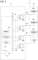
- a compression system 1 includes a compression garment 10 for applying sequential compression therapy to a limb or limbs of a wearer and a controller 5 having one or more processors 7 and computer executable instructions embodied on a non-transitory computer readable storage medium (e.g., memory) 33.
- the computer executable instructions include instructions for causing the one or more processors 7 to control operation of the compression system 1.
- the compression garment 10 includes a distal inflatable bladder 13a, an intermediate inflatable bladder 13b, and a proximal inflatable bladder 13c.
- the compression garment 10 can be fastened around the wearer's limb and, in some embodiments, is adjustable to fit limbs of different circumferences.
- the inflatable bladders 13a, 13b, 13c in some embodiments, extend at least partially around a portion of the wearer's limb.
- inflatable bladders 13a, 13b, 13c may be posterior-only bladders.
- the controller 5 determines, based at least in part on a measured pressure of one or more of the inflatable bladders 13a, 13b, 13c, a blood pressure and/or a pulse rate of a wearer around whose limb the compression garment 10 is applied (i.e., in a wrapped configuration around) and, in some embodiments, correlates the blood pressure with an arterial blood pressure and provides an indication of the determined blood pressure and/or correlated arterial blood pressure (e.g., by providing an audible alarm and/or by providing a visual indication on a graphical user interface).
- the controller 5 determines, based at least in part on the measured pressure of one or more of the inflatable bladders 13a, 13b, 13c, a respiration rate of the wearer, changes in peripheral resistance (e.g., due to vasodilating/constricting drugs, etc.), and/or motions of the wearer (e.g., monitoring patient motion).
- the controller 5 can control operation of the compression system 1 to perform an inflation cycle, in which the inflatable bladders 13a, 13b, 13c are inflated to apply pressure to the wearer's limb to establish, for example, a gradient pressure applied to the wearer's limb by inflatable bladders 13a, 13b, 13c of the compression garment 10 during one or more compression cycles.
- each therapeutic compression cycle can include an inflation phase for each of the bladders 13a, 13b, 13c, a decay phase for each of the bladders 13a and 13b, and a decompression or vent phase for each of the bladders 13a, 13b, 13c.
- the end-of-cycle pressure of each bladder 13a, 13b, 13c is the pressure in each bladder 13a, 13b, 13c prior to initiation of the decompression phase of the respective bladder 13a, 13b, 13c.
- the compression garment 10 is a thigh-length sleeve positionable around the leg of the wearer, with the distal bladder 13a around the wearer's ankle, the intermediate bladder 13b around the wearer's calf, and the proximal bladder 13c around the wearer's thigh.
- the inflatable bladders 13a, 13b, 13c expand and contract under the influence of fluid (e.g., air or other fluids) delivered from a pressurized fluid source 21 (e.g., a pump or compressor) in electrical communication with the controller 5.
- the pressurized fluid source 21 delivers pressurized fluid (e.g., air) to the inflatable bladders 13a, 13b, 13c through tubing 23.
- each inflatable bladder 13a, 13b, 13c is in fluid communication with a respective valve 25a, 25b, 25c.
- a pressure sensor 27 is in communication (e.g., fluid communication and/or mechanical communication) with a manifold 29 to measure a signal indicative of pressure in the manifold 29. Fluid communication between the manifold 29 and the respective inflatable bladders 13a, 13b, 13c can be controlled through control of the position of the respective valves 25a, 25b, 25c (e.g., through activation and/or deactivation of the respective valves 25a, 25b, 25c).
- the pressure sensor 27 is in electrical communication with the processor 7 such that the processor 7 receives, from the pressure sensor 27, signals indicative of the pressure of the manifold 29 and/or one or more of the inflatable bladders 13a, 13b, 13c in fluid communication with the manifold 29 as a result of the positions of the respective valves 25a, 25b, 25c. If only one bladder 13a, 13b, or 13c is in fluid communication with the manifold 29, the signal received from the pressure sensor 27 is indicative of the pressure of the respective bladder 13a, 13b, 13c in fluid communication with the manifold 29. For example, the pressure sensor 27 provides a signal indicative of the pressure in the inflatable bladder 13a when valve 25a is open and valves 25b, 25c are closed.
- the pressure sensor 27 provides a signal indicative of the pressure in the bladder 13b when the valve 25b is open and the valves 25a and 25c are closed. Likewise, the pressure sensor 27 provides a signal indicative of the pressure in the inflatable bladder 13c when the valve 25c is open and the valves 25a and 25b are closed.
- a vent valve 25d is actuatable to control fluid communication between the manifold 29 and a vent port, which vents to ambient atmosphere. All bladders 13a, 13b, 13c can be vented using the vent valve 25d.
- Each valve 25a, 25b, 25c is a 2-way/2-position, normally open, solenoid valve.
- Each valve 25a, 25b, 25c includes two ports and is actuatable to place an inlet port in fluid communication with a bladder port in a first, open position.
- Each valve 25a, 25b, 25c is further actuatable to shut off fluid communication between the inlet port and the bladder port.
- the inlet port of each valve 25a, 25b, 25c is in fluid communication with the pressurized fluid source 21 and the manifold 29.
- the bladder port of each valve 25a, 25b, 25c is in fluid communication with a respective inflatable bladder 13a, 13b, 13c.
- any one of the bladders 13a, 13b, 13c can be placed in fluid communication with the pressurized fluid source 21 and the manifold 29 by the respective valve 25a, 25b, 25c to deliver pressurized fluid to the bladder 13a, 13b, 13c.
- the respective valve 25a, 25b, 25c can be closed to hold the fluid in the respective bladder 13a, 13b, 13c.
- the bladders 13a, 13b, 13c of the compression garment 10 can be individually inflated by opening the respective valve 25a, 25b, 25c and closing the other valves 25a, 25b, 25c so that only the one bladder 13a, 13b, 13c associated with the opened valve 25a, 25b, 25c is in fluid communication with the pressurized fluid source 21 and the manifold 29.
- the vent valve 25d is also a 2-way/2-position, normally open, solenoid valve.
- the vent valve 25d includes two ports and is actuatable to place an inlet port in fluid communication with a vent port in a first position.
- the vent inlet port is in fluid communication with a vent port in a first position.
- the vent valve 25d is further actuatable to shut off fluid communication between the inlet port and the vent port.
- the inlet port of vent valve 25d is in fluid communication with the pressurized fluid source 21 and the manifold 29.
- the vent port of the vent valve 25d is in fluid communication with ambient atmosphere.
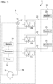
- valves 25a, 25b, 25c, 25d of Fig. 2 could be other types and have other arrangements within the compression system 1 without departing from the scope of the present disclosure.
- the valves may be valves 35a, 35b, 35c, which are 3-way/2-position solenoid valves and are actuatable to control the pressure in bladders 13a, 13b, 13c without a vent valve.
- the computer executable instructions embodied on the non-transitory, computer readable storage medium 33 can include instructions to cause the one or more processors 7 to pressurize (e.g., inflate) the inflatable bladders 13a, 13b, 13c to provide cyclical therapeutic compression pressure to a wearer's limb.
- the computer executable instructions embodied on the non-transitory, computer readable storage medium 33 can include instructions to cause the one or more processors 7 to control the pressurized fluid source 21 and/or the valves 25a, 25b, 25c, 25d to pressurize the inflatable bladders 13a, 13b, 13c to therapeutic compression pressures for a predetermined amount of time to move the blood in the limb from regions underlying the inflatable bladders 13a, 13b, 13c.
- the one or more processors 7 can use timing signals and/or timing data provided by the timer 31 to measure the amount of time the inflatable bladders 13a, 13b, 13c are pressurized.
- the timer 31 can be comprised of a clock, one or more timer circuits (e.g., 555 timer integrated circuits, etc.), computer executable instructions that comprise timing routines, and/or other timers familiar to those skilled in the art.
- the length of time the bladder 13a, 13b, 13c is held at the compression pressure is referred to herein as a decay phase. Following the decay phase is a decompression phase.
- the computer executable instructions include instructions to cause the one or more processors 7 to control the pressurized fluid source 21 and/or the valves 25a, 25b, 25c, 25d to reduce the pressure in the inflatable bladders 13a, 13b, 13c to a lower pressure (e.g., atmospheric pressure).
- the compression system 1 can determine a blood pressure, a pulse rate, a respiration rate, changes in peripheral resistance, and/or motions of a wearer around whose limb the compression garment 10 is applied (i.e., in a wrapped configuration around) and, in certain embodiments, can provide an indication of that determination, which can facilitate, for example, monitoring the wearer's vital parameters with compression garment 10 and tracking the wearer's compliance with a prescribed therapeutic use of the compression garment 10. For example, monitoring vital parameters via compression garment 10 reduces the negative impact to wearer comfort that would result from utilizing a sphygmomanometer or the like in addition to compression garment 10.
- the computer executable instructions embodied on the non-transitory, computer readable storage medium 33 include instructions to cause the one or more processors 7 to analyze pressure signal data received from the pressure sensor 27 during a static period of a therapeutic cycle of the compression system 1.
- the computer executable instructions embodied on the non-transitory, computer readable storage medium 33 include instructions to cause the one or more processors 7 to detect waveform peaks in the output of pressure sensor 27 correlated to a heartbeat range of the wearer, determine a frequency of the waveform peaks, and assess the oscillation amplitude for blood pressure estimation.
- the computer executable instructions embodied on the non-transitory, computer readable storage medium 33 include instructions to cause the one or more processors 7 to, based on magnitude of the oscillating amplitude, utilize one or more algorithms to estimate a blood pressure of the wearer around whose limb the compression garment 10 is applied.
- the computer executable instructions embodied on the non-transitory, computer readable storage medium 33 include instructions to cause the one or more processors 7 to correlate the estimated blood pressure of the wearer based on magnitude of the oscillating amplitude with a corresponding arterial blood pressure of the wearer around whose limb the compression garment 10 is applied.
- the computer executable instructions cause the one or more processors 7 to receive pressure signal data from the pressure sensor 27.
- the computer executable instructions can include instructions to cause the one or more processors 7 to process a single waveform representative of the pressures within one or more of the bladders 13a, 13b, 13c. It should be appreciated that the one or more processors 7 may process multiple waveforms without departing from the scope of the present disclosure.
- the one or more processors 7 can detect certain characteristics on the waveform that are indicative of a heartbeat of the wearer.
- the pressure sensor 27 remains (or is intentionally placed) in constant communication (e.g., fluidic and/or mechanical communication) with one or more of the bladders 13a, 13b, 13c.
- Exemplary static periods include non-therapeutic cycles (e.g., pressures in bladders 13a, 13b, 13c of less than about 25 mmHg), a subset of an initial garment detection period, an extension of a therapy cycle, and/or a venous refill measurement period.
- the computer-executable instructions embodied on the computer readable storage medium 33 include instructions to cause the one or more processors 7 to activate one or more valves 35a, 35b, 35c for one or more of a particular bladder 13a, 13b, 13c such that a fluidic path is established between the pressure sensor 27 and one or more of the bladders 13a, 13b, 13c.
- the computer-executable instructions embodied on the computer readable storage medium 33 include instructions to cause the one or more processors 7 to open or close the vent valve 25d such that the manifold 29 can no longer vent.
- One or more of the computer-executable instructions causes the one or more processors 7 to determine whether the signal received from the pressure sensor 27 includes oscillatory characteristics (e.g., a substantially sinusoidal pattern) indicative of the presence of a heartbeat (i.e., pulse) of the wearer of the compression garment 10.
- a pulse of a wearer of the compression garment can produce a signal with oscillatory characteristics carried on the overall pressure waveform. It should be appreciated that these oscillatory characteristics can be extracted through signal processing of the overall pressure waveform.
- a volume of fluid e.g., air
- a signal from the pressure sensor 27 during a representative bladder inflation period 41 and pressure hold period 43 pressure profile of one of the bladders 13a, 13b, 13c for a wrapped configuration of the compression garment 10 is shown.
- the pressure hold period 43 is about twenty seconds in duration and represents one of the bladders 13a, 13b, or 13c inflated to about 200 mmHg.
- bladders 13a, 13b, or 13c may be inflated to about 160 mmHg or greater in order to detect wearer blood pressure.
- the computer executable instructions embodied on the non-transitory, computer readable storage medium 33 include instructions to cause the one or more processors 7 to receive signals from the pressure sensor 27 that are indicative of the bladder pressures during the bladder inflation period 41 and the pressure hold period 43.
- the computer executable instructions can further include instructions to cause the one or more processors 7 to refine the signal from the pressure sensor 27 to extract, from the signal received during the pressure hold period 43, frequencies associated with typical human cardiac cycles.
- the one or more processors 7 can extract (e.g., through band-pass filtering) frequencies in the range of 0.5 Hz to 25 Hz.
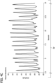
- Fig. 4C shows a waveform 43' that is the result of a band-pass filtering technique applied to the signal of interest of the pressure hold period 43 such that the relevant frequency range (e.g., 0.5 Hz to 25 Hz) has been extracted.
- the filtered signal 43' brings the oscillations associated with a pulse of a wearer into focus such that the oscillations are more prevalent when displayed by a display device.
- the one or more processors 7 filter the signal 43 to remove frequencies that are not associated with a pulse of wearer such that data associated with the resulting filtered signal 43' is further analyzed by the one or more processors 7 as part of peak detection and compliance monitoring algorithms, as described in further detail below. It should be appreciated that, as described herein, the one or more processors 7 detect pulsation associated with the heartbeat of the wearer of the compression garment 10 and not the actual heart rate of the wearer.
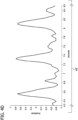
- Fig. 4D shows a subset portion of the waveform 43' indicative of the band-pass filtered signal of interest (e.g., an enlarged, fragmentary view of Fig. 4C ).
- Fig. 5 is a schematic representation of an exemplary method 500 of analyzing waveform data received from the pressure sensor 27 to determine a blood pressure and/or a pulse rate of a wearer around whose limb the compression garment 10 is applied by detecting pulsations associated with the heartbeat of the wearer.
- This exemplary method can be carried out by the one or more processors 7 through execution of computer executable instructions embodied on the non-transitory, computer readable storage medium 33.
- the one or more processors 7 execute computer executable instructions to sample 502 initial pressure.
- the initial pressure sampling is done at a rate of 100 Hz or higher and typical signal conditioning is used to remove baseline noise.
- the sampling 502 may be expanded to include attenuation of frequencies just under a low cutoff (e.g., 0.25 Hz).
- a post-process waveform analysis 504 further includes a bandpass filter 506, an additional filtering 508, and a peak detection 510.
- the bandpass filter 506 the signal of interest is filtered using a bandpass filtering technique in a typical range of frequencies associated with a typical heartrate range of a human wearer (e.g., 0.5-25 Hz for a human wearer).
- the additional filtering 508 the peaks of the bandpass filtered signal are further refined.
- the additional filtering can include a lowpass filter with a cutoff of 5 Hz to produce a filtered value. Additionally or alternatively, the additional filtering can include a smoothing algorithm using the five most recent samples of the moving range to produce a filtered value. It should be appreciated that more than one filtering technique may be applied to the bandpass filtered signal during the additional filtering step 508.
- a peak detection is performed to check that the peaks of the filtered signal correspond to a heartbeat range of a typical human wearer.
- the peak detection 510 can be based on a predetermined threshold (e.g., look only at peaks with a magnitude greater than 0.05 mmHg). Additionally or alternatively, the peak detection 510 can be based on examining for repeating signals with frequencies within a heartbeat range of a typical human wearer, independent of magnitude (e.g., expanded to 30-120 bpm for margin). For example, a frequency analysis computation may be performed to check that a repeating signal with frequency within the heartbeat range of a typical human wearer is detected.
- the peak detection 510 can be based on the highest magnitude peaks and checking that the frequency of those peaks falls within the expected heartbeat range of a typical human wearer. It should be appreciated that more than one peak detection technique may be used during the peak detection 510. In some embodiments, peak detection 510 includes a combination of peak detection based on a predetermined threshold and based on the highest magnitude peaks and checking that the frequency of those peaks falls within the expected heartbeat range of a typical human wearer because the signal-to-noise ratio is high enough that the pulses are plainly evident.
- the computer executable instructions cause the one or more processors 7 to determine 512 whether features of a pulse of the wearer were detected during the peak detection 510. If features of a pulse are determined 512 to be present, the results of a positive determination can be indicated 516.
- the indication 516 can include sending a visual representation to a display device associated with the compression system 1. Additionally or alternatively, the indication 516 can include incrementing and/or pausing a timer (e.g., timer 31). Additionally or alternatively, if features of a pulse are determined 512 to be present, computer executable instructions cause the one or more processors 7 to correlate a determined blood pressure with an arterial blood pressure of the wearer.
- the process ends at step 518 and returns back to step 502. If an impulse is not detected at step 512, the computer executable instructions cause the one or more processors 7 to return a null value at step 514. After step 514, the process ends at step 518 and returns to sampling 502.
- a controller for controlling inflation and deflation of at least one bladder (e.g., bladders 13a, 13b, 13c) of a garment to provide compression therapy treatment to a wearer of the garment includes one or more processors (e.g., processors 7), and a non-transitory, computer-readable storage medium (e.g., non-transitory computer readable storage medium 33).
- processors e.g., processors 7
- non-transitory, computer-readable storage medium e.g., non-transitory computer readable storage medium 33
- the non-transitory, computer-readable storage medium includes computer-executable instructions for causing the one or more processors to receive, from a pressure sensor (e.g., pressure sensor 27), a signal indicative of fluid pressure in the at least one bladder of the garment and determine whether the received signal includes oscillating amplitude as a function of time (e.g., timing signals and/or timing data provided by timer 31).
- the non-transitory, computer-readable storage medium also includes computer-executable instructions for causing the one or more processors to estimate a blood pressure of the wearer of the garment based at least in part on the determination of whether the received signal includes oscillating amplitude as a function of time.
- the instructions to receive the signal indicative of fluid pressure include instructions to receive the signal indicative of fluid pressure while the at least one bladder is inflated.
- the instructions to receive the signal indicative of fluid pressure include instructions to receive the signal indicative of fluid pressure while the at least one bladder is inflated at a substantially constant pressure.
- the substantially constant pressure changes by less than ten percent over the period of determination.
- the instructions to receive the signal indicative of fluid pressure include instructions to receive the signal indicative of fluid pressure over a period of greater than about 5 seconds and less than about 60 seconds.
- the instructions to receive the signal indicative of fluid pressure include instructions to receive the signal indicative of fluid pressure at a predetermined interval.
- the instructions to receive the signal indicative of fluid pressure include instructions to receive the signal between therapeutic compression cycles of the at least one bladder.
- the instructions to receive the signal indicative of fluid pressure include instructions to receive the signal based at least in part on a user input.
- the non-transitory, computer-readable storage medium further includes computer-executable instructions for causing the one or more processors to detect whether the at least one bladder of the compression garment is in communication with the pressure sensor and the instructions to receive the signal indicative of fluid pressure include instructions to receive the signal based at least in part on detection of the communication between the at least one bladder and the pressure sensor.
- the detected communication between the compression garment and the pressure sensor is fluid communication.
- the instructions to receive the signal indicative of fluid pressure include instructions to receive the signal indicative of fluid pressure while the at least one bladder is inflated to a non-therapeutic pressure.
- the non-therapeutic pressure is about 160 mmHg or greater.
- the instructions to receive the signal indicative of fluid pressure include instructions to receive a first signal indicative of fluid pressure in a first bladder and to receive a second signal indicative of fluid pressure in a second bladder, and the instructions to determine whether the received signal includes oscillating amplitude includes instructions to determine whether the first signal and the second signal each include oscillating amplitude.
- the instructions to determine whether the received signal includes oscillating amplitude include instructions to band-pass filter (e.g., bandpass filter 506) the received signal to extract frequencies of about 0.5 Hz to about 25 Hz.
- band-pass filter e.g., bandpass filter 506
- the instructions to determine whether the received signal includes oscillating amplitude further include instructions to smooth (e.g., additional filtering 508) the band-pass filtered signal.
- the instructions to determine whether the received signal includes oscillating amplitude further include instructions to low-pass filter (e.g., additional filtering 508) the band-pass filtered signal at a frequency of about 5 Hz or under.
- low-pass filter e.g., additional filtering 508
- the instructions to determine whether the received signal includes oscillating amplitude include instructions to detect peaks (e.g., peak detection 510) in the signal.
- the instructions to detect peaks in the signal include instructions to detect peaks in a frequency range of about 0.5 Hz to about 4 Hz.
- the instructions to detect peaks in the signal include instructions to detect peaks corresponding to a variation in the fluid pressure of greater than about 0.05 mmHg.
- the instructions to determine whether the received signal includes oscillating amplitude include instructions to detect a repeating signal within a frequency range of about 0.5 Hz to about 4 Hz.
- the oscillating amplitude as a function of time of the received signal is representative of a pulse of the wearer of the garment.
- the non-transitory, computer-readable storage medium further includes computer-executable instructions for correlating the estimated blood pressure with an arterial blood pressure of the wearer.
- a system (e.g., compression system 1) includes a compression garment (e.g., compression garment 10) including at least one inflatable and deflatable bladder (e.g., bladders 13a, 13b, 13c) and the compression garment is securable about one or more limbs of a wearer.
- the system further includes a controller (e.g., controller 5) for controlling inflation and deflation of at least one bladder of the garment to provide compression therapy treatment to a wearer of the garment.
- the controller includes one or more processors (e.g., processors 7), and a memory (e.g., non-transitory, computer-readable storage medium 33) that includes instructions for causing the one or more processors to receive, from a pressure sensor (e.g., pressure sensor 27), a signal indicative of fluid pressure in the at least one bladder of the garment and determine whether the received signal includes oscillating amplitude as a function of time (e.g., timing signals and/or timing data provided by timer 31).
- a pressure sensor e.g., pressure sensor 27
- a signal indicative of fluid pressure in the at least one bladder of the garment e.g., a signal indicative of fluid pressure in the at least one bladder of the garment and determine whether the received signal includes oscillating amplitude as a function of time (e.g., timing signals and/or timing data provided by timer 31).
- the non-transitory, computer-readable storage medium also includes computer-executable instructions for causing the one or more processors to estimate the blood pressure of the wearer of the garment based at least in part on the determination of whether the received signal includes oscillating amplitude as a function of time.
- this can include oscillometric techniques that inflate the bladder to a pressure sufficient to collapse the underlying arterial vessels.
- the collapse pressure is referred to as systolic pressure and the pressure which leads to the maximum pulsation amplitude is referred to as the mean arterial pressure.
- Alternative techniques can leverage pulsewave velocity theory to provide a more continuous blood pressure measurement.
- the oscillating waveform is first measured in one of the bladders and a second bladder is used to measure the time it takes for the same pressure waveforms to travel along the arterial tree to the second bladder. The less time it takes, the higher the underlying pressure.
- the inflation profile of a first bladder can be used to generate a measured signal in a second bladder. The known, generated signal can then be used to cancel noise associated with patient motion to improve the fidelity of the underlying blood pressure waveform.
- the system further includes a pump (e.g., pressurized fluid source 21) and at least one valve (e.g., valves 25a, 25b, 25c) that is in fluid communication with the pump and the at least one inflatable and deflatable bladder.
- the at least one valve is in electrical communication with the controller and the non-transitory, computer-readable storage medium of the controller also includes computer-executable instructions for causing the one or more processors to actuate the at least one valve to control fluid communication between the pump and the at least one inflatable and deflatable bladder.
- the system also includes a pump in fluid communication with the at least one inflatable and deflatable bladder.
- the pump is in electrical communication with the controller and the non-transitory, computer-readable storage medium of the controller also includes computer-executable instructions for causing the one or more processors to adjust a speed of the pump.
- the at least one inflatable and deflatable bladder extends at least partially around a portion (e.g., up to and including a circumference) of the limb of the wearer when secured about the limb of the wearer.
- a controller for controlling inflation and deflation of at least one bladder (e.g., bladders 13a, 13b, 13c) of a garment (e.g., compression garment 10) to provide compression therapy treatment to a wearer of the garment includes one or more processors (e.g., processors 7) and a non-transitory, computer-readable storage medium (e.g., non-transitory computer readable storage medium 33).
- the non-transitory, computer-readable storage medium includes computer-executable instructions for causing the one or more processors to receive, from a pressure sensor (e.g., pressure sensor 27), a signal indicative of fluid pressure in the at least one bladder of the garment, and determine whether the received signal includes a representation of a pulse of the wearer.
- the non-transitory, computer-readable storage medium also includes computer-executable instructions for causing the one or more processors to determine a blood pressure of the wearer of the garment based at least in part on the determination of whether the received signal includes a signal indicative of the pulse of the wearer.
- the instructions to receive the signal indicative of fluid pressure include instructions to receive the signal indicative of fluid pressure while the at least one bladder is inflated.
- the instructions to receive the signal indicative of fluid pressure include instructions to receive the signal indicative of fluid pressure while the at least one bladder is inflated at a substantially constant pressure.
- the instructions to determine whether the received signal includes a representation of a pulse of the wearer include instructions to detect a repeating signal within a frequency range of about 0.5 Hz to about 4 Hz.
- the computer-executable instructions include instructions for correlating the determined blood pressure with an arterial blood pressure of the wearer.
- a system (e.g., compression system 1) includes a compression garment (e.g., compression garment 10) including at least one inflatable and deflatable bladder (e.g., bladders 13a, 13b, 13c) and the compression garment is securable about a limb of a wearer.
- the system further includes a controller (e.g., controller 5) for controlling inflation and deflation of at least one bladder of the garment to provide compression therapy treatment to the wearer of the garment.
- the controller includes one or more processors (e.g., processors 7), and a non-transitory, computer-readable storage medium (e.g., non-transitory, computer readable storage medium 33) that includes instructions for causing the one or more processors to receive, from a pressure sensor (e.g., pressure sensor 27), a signal indicative of fluid pressure in the at least one bladder of the garment, and determine whether the received signal includes a representation of a pulse of the wearer.
- the non-transitory, computer-readable storage medium also includes computer-executable instructions for causing the one or more processors to determine a blood pressure of the wearer of the garment based at least in part on the determination of whether the received signal includes a signal indicative of the pulse of the wearer.
- the system also includes a pump (e.g., pressurized fluid source 21) and at least one valve (e.g., valves 25a, 25b, 25c).
- the at least one valve is in fluid communication with the pump and the at least one inflatable and deflatable bladder.
- the at least one valve is also in electrical communication with the controller.
- the non-transitory, computer-readable storage medium of the controller also includes computer-executable instructions for causing the one or more processors to actuate the at least one valve to control fluid communication between the pump and the at least one inflatable and deflatable bladder.
- the system also includes a pump in fluid communication with the at least one inflatable and deflatable bladder.
- the pump is in electrical communication with the controller.
- the non-transitory, computer-readable storage medium of the controller also includes computer-executable instructions for causing the one or more processors to adjust a speed of the pump.
- Embodiments can include one or more of the following advantages.
- a determination of a blood pressure of a wearer is performed using a signal indicative of pressure in an inflatable bladder of the compression garment during a static period, providing a real-time and automated indication of the blood pressure of a wearer.
- the real-time and automated indication of blood pressure of the wearer described herein can provide for a more accurate blood pressure measurement, a more accurate indication of patient compliance with treatment protocols, and/or can reduce the burden on the caregiver with respect to monitoring patient vital parameters.
- the indication of blood pressure of the wearer described herein can provide for monitoring of wearer vital parameters with minimal equipment and enhanced comfort.
- compression systems have been described as being used with thigh length compression sleeves, it should be understood that the compression systems can additionally or alternatively be used with other types of compression garments.
- the compression systems can be used with knee-length compression sleeves and/or with sleeves having a different number of bladders configured to be disposed over different areas of the wearer's body.
- Embodiments can be implemented in digital electronic circuitry, or in computer hardware, firmware, software, or in combinations thereof.
- the controller of the compression system can be implemented in a computer program product tangibly embodied or stored in a machine-readable storage device for execution by a programmable processor; and method actions can be performed by a programmable processor executing a program of instructions to perform functions of the controller of the compression system by operating on input data and generating output.
- the controller of the compression system can be implemented in one or more computer programs that are executable on a programmable system including at least one programmable processor coupled to receive data and instructions from, and to transmit data and instructions to, a data storage system, at least one input device, and at least one output device.
- Each computer program can be implemented in a high-level procedural or object oriented programming language, or in assembly or machine language if desired; and in any case, the language can be a compiled or interpreted language.
- Suitable processors include, by way of example, special purpose microprocessors. Generally, a processor will receive instructions and data from a read-only memory and/or a random access memory. Generally, a computer will include one or more mass storage devices for storing data files; such devices include magnetic disks, such as internal hard disks and removable disks; magneto-optical disks; and optical disks. Storage devices suitable for tangibly embodying computer program instructions and data include all forms of non-volatile memory, including by way of example semiconductor memory devices, such as EPROM, EEPROM, and flash memory devices; magnetic disks such as internal hard disks and removable disks; magneto-optical disks; and CD-ROM disks. Any of the foregoing can be supplemented by, or incorporated in, ASICs (application-specific integrated circuits) or FPGAs (field programmable logic arrays).
- ASICs application-specific integrated circuits
- FPGAs field programmable logic arrays
Landscapes
- Health & Medical Sciences (AREA)
- Life Sciences & Earth Sciences (AREA)
- Engineering & Computer Science (AREA)
- Veterinary Medicine (AREA)
- Public Health (AREA)
- General Health & Medical Sciences (AREA)
- Animal Behavior & Ethology (AREA)
- Heart & Thoracic Surgery (AREA)
- Cardiology (AREA)
- Biomedical Technology (AREA)
- Medical Informatics (AREA)
- Molecular Biology (AREA)
- Surgery (AREA)
- Biophysics (AREA)
- Physics & Mathematics (AREA)
- Pathology (AREA)
- Physiology (AREA)
- Vascular Medicine (AREA)
- Epidemiology (AREA)
- Pain & Pain Management (AREA)
- Physical Education & Sports Medicine (AREA)
- Rehabilitation Therapy (AREA)
- Anesthesiology (AREA)
- Hematology (AREA)
- Mechanical Engineering (AREA)
- Ophthalmology & Optometry (AREA)
- Psychiatry (AREA)
- Computer Vision & Pattern Recognition (AREA)
- Signal Processing (AREA)
- Artificial Intelligence (AREA)
- Textile Engineering (AREA)
- Dentistry (AREA)
- Pulmonology (AREA)
- Massaging Devices (AREA)
- Measuring Pulse, Heart Rate, Blood Pressure Or Blood Flow (AREA)
- Measuring And Recording Apparatus For Diagnosis (AREA)
Description
- Intermittent pneumatic compression (IPC) systems include devices used to apply pressurized fluid, such as air, to a limb of a patient or wearer. In some instances, pressurized air is applied to the lower limb of a patient at risk for the formation of a blood clot (thrombus) associated with deep vein thrombosis (DVT). An IPC system typically includes a pumping unit to manage pressurization of the fluid, a tubing set to extend the delivery of fluid beyond the pumping unit, and a compression garment which is wrapped around the patient's limb and contains the pressurized fluid. The IPC system intermittently pressurizes the garment to apply therapeutic compression to the patient's limb, moving blood from that area of the limb. Many IPC systems utilize a pressure sensor as the sole means of feedback. The pressure sensor output is used to adjust fluid delivery to the compression garment and maintain prescribed pressures, but the measurable pressure is confined to the pressure within the compression garment and tubing.
-
US 2001/000262 A1 discloses an apparatus for applying an adaptable pressure waveform to a patient's limb for augmenting venous blood flow in the limb. -
WO 02/055007 A2 -
US 2003/069507 A1 discloses a blood-pressure measuring apparatus including a cuff worn on a body portion of a subject to apply a pressure to the body portion. -
US 2010/324429 A1 discloses single- or dual-bladder devices for remote ischemic preconditioning and blood pressure monitoring along with various oscillometry-based and other methods for detecting systolic and diastolic blood pressure while the ischemic preconditioning treatment is in progress. -
US 4718427 A discloses an apparatus and related methods for continuous long-term non-invasive measurement of the pressure of a pulsatile fluid flowing through a flexible tube, particularly human arterial blood flow. - The present disclosure is directed to systems and methods of determining a blood pressure and/or a pulse rate of a compression garment wearer.
- A controller according to a first aspect is recited in
Claim 1. A system according to a second aspect is recited in Claim 13. - In one aspect, a controller for controlling inflation and deflation of at least one bladder of a garment to provide compression therapy treatment to a wearer of the garment includes a memory, one or more processors, and a non-transitory, computer-readable storage medium. The non-transitory, computer-readable storage medium includes computer-executable instructions for causing the one or more processors to receive, from a pressure sensor, a signal indicative of fluid pressure in the at least one bladder of the garment and determine whether the received signal includes oscillating amplitude as a function of time. The non-transitory, computer-readable storage medium also includes computer-executable instructions for causing the one or more processors to estimate a blood pressure of the wearer of the garment based at least in part on the determination of whether the received signal includes oscillating amplitude as a function of time.
- In another aspect, a system includes a compression garment including at least one inflatable and deflatable bladder and the compression garment is securable about a limb of a wearer. The system further includes a controller for controlling inflation and deflation of at least one bladder of a garment to provide compression therapy treatment to a wearer of the garment. The controller includes a memory, one or more processors, and a non-transitory, computer-readable storage medium that includes instructions for causing the one or more processors to receive, from a pressure sensor, a signal indicative of fluid pressure in the at least one bladder of the garment and determine whether the received signal includes oscillating amplitude as a function of time. The non-transitory, computer-readable storage medium also includes computer-executable instructions for causing the one or more processors to estimate the blood pressure of the wearer of the garment based at least in part on the determination of whether the received signal includes oscillating amplitude as a function of time.
- In another aspect, a controller for controlling inflation and deflation of at least one bladder of a garment to provide compression therapy treatment to a wearer of the garment includes a memory, one or more processors, and a non-transitory, computer-readable storage medium. The non-transitory, computer-readable storage medium includes computer-executable instructions for causing the one or more processors to receive, from a pressure sensor, a signal indicative of fluid pressure in the at least one bladder of the garment, and determine whether the received signal includes a representation of a pulse of the wearer. The non-transitory, computer-readable storage medium also includes computer-executable instructions for causing the one or more processors to determine a blood pressure of the wearer of the garment based at least in part on the determination of whether the received signal includes a signal indicative of the pulse of the wearer.
- In another aspect, a system includes a compression garment including at least one inflatable and deflatable bladder and the compression garment is securable about a limb of a wearer. The system further includes a controller for controlling inflation and deflation of at least one bladder of a garment to provide compression therapy treatment to a wearer of the garment. The controller includes a memory, one or more processors, and a non-transitory, computer-readable storage medium that includes instructions for causing the one or more processors to receive, from a pressure sensor, a signal indicative of fluid pressure in the at least one bladder of the garment, and determine whether the received signal includes a representation of a pulse of the wearer. The non-transitory, computer-readable storage medium also includes computer-executable instructions for causing the one or more processors to determine a blood pressure of the wearer of the garment based at least in part on the determination of whether the received signal includes a signal indicative of the pulse of the wearer.
- Embodiments can include one or more of the following advantages.
- In some embodiments, a determination of a blood pressure of a wearer is performed using a signal indicative of pressure in an inflatable bladder of the compression garment during a static period, providing a real-time and automated indication of the blood pressure of a wearer. As compared to observations of multiple medical devices made by a caregiver, the real-time and automated indication of blood pressure of the wearer described herein can provide for a more accurate blood pressure measurement, a more accurate indication of patient compliance with treatment protocols, and/or can reduce the burden on the caregiver with respect to monitoring patient vital parameters. As compared to monitoring vital parameters of a wearer who is receiving treatment, the indication of blood pressure of the wearer described herein can provide for monitoring of wearer vital parameters with minimal equipment and enhanced comfort.
- Other aspects, features, and advantages will be apparent from the description and drawings, and from the claims.
-
-
FIG. 1 is a perspective of a compression system including a compression garment and a controller. -
FIG. 2 is a schematic of an exemplary compression system ofFig. 1 , including a schematic of a pneumatic circuit. -
FIG. 3 is a schematic of another exemplary compression system ofFig. 1 , including a schematic of a pneumatic circuit. -
FIGS. 4A-4D are graphical representations of a pressure profile produced by the compression system ofFig. 1 when a compression garment of the system is in a wrapped configuration on a limb of a wearer. -
FIG. 5 is a flow diagram of a method of compliance monitoring using the compression system ofFig. 1 . - As used herein, the terms "proximal" and "distal" represent relative locations of components, parts and the like of a compression garment when the garment is worn. For example, a "proximal" component is disposed most adjacent to the wearer's torso, a "distal" component is disposed most distant from the wearer's torso, and an "intermediate" component is disposed generally anywhere between the proximal and distal components. Further, as used herein, the terms "wrapped" and "unwrapped" define conditions of the garment where the garment is properly applied to the wearer's limb (e.g., wrapped, worn, etc.) and where the garment is removed from the wearer's limb (e.g., unwrapped, unworn, etc.).
- Aspects of the disclosure herein are related to
U.S. Patent Application Serial No. 15/290,026, filed October 11, 2016 PCT application number PCT/US2016/056296 , filed on October 10, 2016, and the applications from which they claim priority:U.S. Provisional Patent Application Serial Nos. 62/239,527 62/239,493 62/239,566, all filed October 9, 2015 U.S. Provisional Patent Application Serial No. 62/329,233, filed April 29, 2016 - Referring to
Figs. 1 and2 , acompression system 1 includes acompression garment 10 for applying sequential compression therapy to a limb or limbs of a wearer and acontroller 5 having one ormore processors 7 and computer executable instructions embodied on a non-transitory computer readable storage medium (e.g., memory) 33. The computer executable instructions include instructions for causing the one ormore processors 7 to control operation of thecompression system 1. Thecompression garment 10 includes a distalinflatable bladder 13a, an intermediateinflatable bladder 13b, and a proximalinflatable bladder 13c. Thecompression garment 10 can be fastened around the wearer's limb and, in some embodiments, is adjustable to fit limbs of different circumferences. Theinflatable bladders inflatable bladders - As described in further detail below, the
controller 5 determines, based at least in part on a measured pressure of one or more of theinflatable bladders compression garment 10 is applied (i.e., in a wrapped configuration around) and, in some embodiments, correlates the blood pressure with an arterial blood pressure and provides an indication of the determined blood pressure and/or correlated arterial blood pressure (e.g., by providing an audible alarm and/or by providing a visual indication on a graphical user interface). In additional or alternative embodiments, thecontroller 5 determines, based at least in part on the measured pressure of one or more of theinflatable bladders controller 5 can control operation of thecompression system 1 to perform an inflation cycle, in which theinflatable bladders inflatable bladders compression garment 10 during one or more compression cycles. As also described in further detail below, each therapeutic compression cycle can include an inflation phase for each of thebladders bladders bladders bladder bladder respective bladder - The
compression garment 10 is a thigh-length sleeve positionable around the leg of the wearer, with thedistal bladder 13a around the wearer's ankle, theintermediate bladder 13b around the wearer's calf, and theproximal bladder 13c around the wearer's thigh. Theinflatable bladders controller 5. The pressurizedfluid source 21 delivers pressurized fluid (e.g., air) to theinflatable bladders tubing 23. - Referring to
Fig. 2 , eachinflatable bladder respective valve pressure sensor 27 is in communication (e.g., fluid communication and/or mechanical communication) with amanifold 29 to measure a signal indicative of pressure in themanifold 29. Fluid communication between themanifold 29 and the respectiveinflatable bladders respective valves respective valves pressure sensor 27 is in electrical communication with theprocessor 7 such that theprocessor 7 receives, from thepressure sensor 27, signals indicative of the pressure of themanifold 29 and/or one or more of theinflatable bladders manifold 29 as a result of the positions of therespective valves bladder pressure sensor 27 is indicative of the pressure of therespective bladder pressure sensor 27 provides a signal indicative of the pressure in theinflatable bladder 13a whenvalve 25a is open andvalves pressure sensor 27 provides a signal indicative of the pressure in thebladder 13b when thevalve 25b is open and thevalves pressure sensor 27 provides a signal indicative of the pressure in theinflatable bladder 13c when thevalve 25c is open and thevalves vent valve 25d is actuatable to control fluid communication between the manifold 29 and a vent port, which vents to ambient atmosphere. Allbladders vent valve 25d. - Each
valve valve valve valve fluid source 21 and the manifold 29. The bladder port of eachvalve inflatable bladder - Any one of the
bladders fluid source 21 and the manifold 29 by therespective valve bladder bladder respective valve respective bladder bladders compression garment 10 can be individually inflated by opening therespective valve other valves bladder valve fluid source 21 and the manifold 29. - The
vent valve 25d is also a 2-way/2-position, normally open, solenoid valve. Thevent valve 25d includes two ports and is actuatable to place an inlet port in fluid communication with a vent port in a first position. The vent inlet port is in fluid communication with a vent port in a first position. Thevent valve 25d is further actuatable to shut off fluid communication between the inlet port and the vent port. The inlet port ofvent valve 25d is in fluid communication with the pressurizedfluid source 21 and the manifold 29. The vent port of thevent valve 25d is in fluid communication with ambient atmosphere. - It should be appreciated that the
valves Fig. 2 could be other types and have other arrangements within thecompression system 1 without departing from the scope of the present disclosure. For example, referring toFig. 3 , the valves may bevalves bladders - With reference again to
Fig. 2 , the computer executable instructions embodied on the non-transitory, computerreadable storage medium 33 can include instructions to cause the one ormore processors 7 to pressurize (e.g., inflate) theinflatable bladders readable storage medium 33 can include instructions to cause the one ormore processors 7 to control the pressurizedfluid source 21 and/or thevalves inflatable bladders inflatable bladders more processors 7 can use timing signals and/or timing data provided by thetimer 31 to measure the amount of time theinflatable bladders timer 31 can be comprised of a clock, one or more timer circuits (e.g., 555 timer integrated circuits, etc.), computer executable instructions that comprise timing routines, and/or other timers familiar to those skilled in the art. The length of time thebladder more processors 7 to control the pressurizedfluid source 21 and/or thevalves inflatable bladders - The
compression system 1 can determine a blood pressure, a pulse rate, a respiration rate, changes in peripheral resistance, and/or motions of a wearer around whose limb thecompression garment 10 is applied (i.e., in a wrapped configuration around) and, in certain embodiments, can provide an indication of that determination, which can facilitate, for example, monitoring the wearer's vital parameters withcompression garment 10 and tracking the wearer's compliance with a prescribed therapeutic use of thecompression garment 10. For example, monitoring vital parameters viacompression garment 10 reduces the negative impact to wearer comfort that would result from utilizing a sphygmomanometer or the like in addition tocompression garment 10. Moreover, monitoring vital parameters viacompression garment 10 reduces the need for healthcare professionals (e.g., nurses) to monitor multiple medical devices which reduces the potential for missed information and/or errors. The computer executable instructions embodied on the non-transitory, computerreadable storage medium 33 include instructions to cause the one ormore processors 7 to analyze pressure signal data received from thepressure sensor 27 during a static period of a therapeutic cycle of thecompression system 1. The computer executable instructions embodied on the non-transitory, computerreadable storage medium 33 include instructions to cause the one ormore processors 7 to detect waveform peaks in the output ofpressure sensor 27 correlated to a heartbeat range of the wearer, determine a frequency of the waveform peaks, and assess the oscillation amplitude for blood pressure estimation. The computer executable instructions embodied on the non-transitory, computerreadable storage medium 33 include instructions to cause the one ormore processors 7 to, based on magnitude of the oscillating amplitude, utilize one or more algorithms to estimate a blood pressure of the wearer around whose limb thecompression garment 10 is applied. The computer executable instructions embodied on the non-transitory, computerreadable storage medium 33 include instructions to cause the one ormore processors 7 to correlate the estimated blood pressure of the wearer based on magnitude of the oscillating amplitude with a corresponding arterial blood pressure of the wearer around whose limb thecompression garment 10 is applied. - In an exemplary embodiment, the computer executable instructions cause the one or
more processors 7 to receive pressure signal data from thepressure sensor 27. The computer executable instructions can include instructions to cause the one ormore processors 7 to process a single waveform representative of the pressures within one or more of thebladders more processors 7 may process multiple waveforms without departing from the scope of the present disclosure. By monitoring the pressure signals and corresponding pressure data during, for example, a static period of the therapy cycle, the one ormore processors 7 can detect certain characteristics on the waveform that are indicative of a heartbeat of the wearer. In certain embodiments, during the static period, thepressure sensor 27 remains (or is intentionally placed) in constant communication (e.g., fluidic and/or mechanical communication) with one or more of thebladders bladders - In an exemplary operation of the embodiment of
Fig. 3 , in which 3-way/2-position valves are utilized, the computer-executable instructions embodied on the computerreadable storage medium 33 include instructions to cause the one ormore processors 7 to activate one ormore valves particular bladder pressure sensor 27 and one or more of thebladders - In an exemplary operation of the embodiment of
Fig. 2 , in which 2-way/2-position valves are utilized, the computer-executable instructions embodied on the computerreadable storage medium 33 include instructions to cause the one ormore processors 7 to open or close thevent valve 25d such that the manifold 29 can no longer vent. One or more of the computer-executable instructions causes the one ormore processors 7 to determine whether the signal received from thepressure sensor 27 includes oscillatory characteristics (e.g., a substantially sinusoidal pattern) indicative of the presence of a heartbeat (i.e., pulse) of the wearer of thecompression garment 10. Because a volume of fluid (e.g., air) is retained within one or more of thebladders - Referring to
Fig. 4A , a signal from thepressure sensor 27 during a representativebladder inflation period 41 and pressure holdperiod 43 pressure profile of one of thebladders compression garment 10 is shown. In this embodiment, thepressure hold period 43 is about twenty seconds in duration and represents one of thebladders bladders - Referring now to
Fig. 4B , a representative subset portion of the received pressure signal duringpressure hold period 43 is shown. For the sake of explanation herein, the subset portion of thepressure hold period 43 inFig. 4B is referred to as a subset signal of interest. The computer executable instructions embodied on the non-transitory, computerreadable storage medium 33 include instructions to cause the one ormore processors 7 to receive signals from thepressure sensor 27 that are indicative of the bladder pressures during thebladder inflation period 41 and thepressure hold period 43. The computer executable instructions can further include instructions to cause the one ormore processors 7 to refine the signal from thepressure sensor 27 to extract, from the signal received during thepressure hold period 43, frequencies associated with typical human cardiac cycles. For example, the one ormore processors 7 can extract (e.g., through band-pass filtering) frequencies in the range of 0.5 Hz to 25 Hz. -
Fig. 4C shows a waveform 43' that is the result of a band-pass filtering technique applied to the signal of interest of thepressure hold period 43 such that the relevant frequency range (e.g., 0.5 Hz to 25 Hz) has been extracted. In some embodiments, the filtered signal 43' brings the oscillations associated with a pulse of a wearer into focus such that the oscillations are more prevalent when displayed by a display device. Additionally or alternatively, the one ormore processors 7 filter thesignal 43 to remove frequencies that are not associated with a pulse of wearer such that data associated with the resulting filtered signal 43' is further analyzed by the one ormore processors 7 as part of peak detection and compliance monitoring algorithms, as described in further detail below. It should be appreciated that, as described herein, the one ormore processors 7 detect pulsation associated with the heartbeat of the wearer of thecompression garment 10 and not the actual heart rate of the wearer. - Referring to
Fig. 4D shows a subset portion of the waveform 43' indicative of the band-pass filtered signal of interest (e.g., an enlarged, fragmentary view ofFig. 4C ). -
Fig. 5 is a schematic representation of an exemplary method 500 of analyzing waveform data received from thepressure sensor 27 to determine a blood pressure and/or a pulse rate of a wearer around whose limb thecompression garment 10 is applied by detecting pulsations associated with the heartbeat of the wearer. This exemplary method can be carried out by the one ormore processors 7 through execution of computer executable instructions embodied on the non-transitory, computerreadable storage medium 33. - The one or
more processors 7 execute computer executable instructions to sample 502 initial pressure. In some embodiments, the initial pressure sampling is done at a rate of 100 Hz or higher and typical signal conditioning is used to remove baseline noise. Additionally or alternatively, thesampling 502 may be expanded to include attenuation of frequencies just under a low cutoff (e.g., 0.25 Hz). - A
post-process waveform analysis 504 further includes abandpass filter 506, anadditional filtering 508, and apeak detection 510. During thebandpass filter 506, the signal of interest is filtered using a bandpass filtering technique in a typical range of frequencies associated with a typical heartrate range of a human wearer (e.g., 0.5-25 Hz for a human wearer). - During the
additional filtering 508, the peaks of the bandpass filtered signal are further refined. The additional filtering can include a lowpass filter with a cutoff of 5 Hz to produce a filtered value. Additionally or alternatively, the additional filtering can include a smoothing algorithm using the five most recent samples of the moving range to produce a filtered value. It should be appreciated that more than one filtering technique may be applied to the bandpass filtered signal during theadditional filtering step 508. - During a
peak detection 510, a peak detection is performed to check that the peaks of the filtered signal correspond to a heartbeat range of a typical human wearer. Thepeak detection 510 can be based on a predetermined threshold (e.g., look only at peaks with a magnitude greater than 0.05 mmHg). Additionally or alternatively, thepeak detection 510 can be based on examining for repeating signals with frequencies within a heartbeat range of a typical human wearer, independent of magnitude (e.g., expanded to 30-120 bpm for margin). For example, a frequency analysis computation may be performed to check that a repeating signal with frequency within the heartbeat range of a typical human wearer is detected. Additionally or alternatively, thepeak detection 510 can be based on the highest magnitude peaks and checking that the frequency of those peaks falls within the expected heartbeat range of a typical human wearer. It should be appreciated that more than one peak detection technique may be used during thepeak detection 510. In some embodiments,peak detection 510 includes a combination of peak detection based on a predetermined threshold and based on the highest magnitude peaks and checking that the frequency of those peaks falls within the expected heartbeat range of a typical human wearer because the signal-to-noise ratio is high enough that the pulses are plainly evident. - The computer executable instructions cause the one or
more processors 7 to determine 512 whether features of a pulse of the wearer were detected during thepeak detection 510. If features of a pulse are determined 512 to be present, the results of a positive determination can be indicated 516. For example, theindication 516 can include sending a visual representation to a display device associated with thecompression system 1. Additionally or alternatively, theindication 516 can include incrementing and/or pausing a timer (e.g., timer 31). Additionally or alternatively, if features of a pulse are determined 512 to be present, computer executable instructions cause the one ormore processors 7 to correlate a determined blood pressure with an arterial blood pressure of the wearer. Upon theindication 516, the process ends atstep 518 and returns back to step 502. If an impulse is not detected atstep 512, the computer executable instructions cause the one ormore processors 7 to return a null value atstep 514. Afterstep 514, the process ends atstep 518 and returns tosampling 502. - In one aspect, a controller (e.g., controller 5) for controlling inflation and deflation of at least one bladder (e.g.,
bladders - In some embodiments, the instructions to receive the signal indicative of fluid pressure include instructions to receive the signal indicative of fluid pressure while the at least one bladder is inflated.
- In certain embodiments, the instructions to receive the signal indicative of fluid pressure include instructions to receive the signal indicative of fluid pressure while the at least one bladder is inflated at a substantially constant pressure.
- In some embodiments, the substantially constant pressure changes by less than ten percent over the period of determination.
- In certain embodiments, the instructions to receive the signal indicative of fluid pressure include instructions to receive the signal indicative of fluid pressure over a period of greater than about 5 seconds and less than about 60 seconds.
- In some embodiments, the instructions to receive the signal indicative of fluid pressure include instructions to receive the signal indicative of fluid pressure at a predetermined interval.
- In certain embodiments, the instructions to receive the signal indicative of fluid pressure include instructions to receive the signal between therapeutic compression cycles of the at least one bladder.
- In some embodiments, the instructions to receive the signal indicative of fluid pressure include instructions to receive the signal based at least in part on a user input.
- In certain embodiments, the non-transitory, computer-readable storage medium further includes computer-executable instructions for causing the one or more processors to detect whether the at least one bladder of the compression garment is in communication with the pressure sensor and the instructions to receive the signal indicative of fluid pressure include instructions to receive the signal based at least in part on detection of the communication between the at least one bladder and the pressure sensor.
- In some embodiments, the detected communication between the compression garment and the pressure sensor is fluid communication.
- In certain embodiments, the instructions to receive the signal indicative of fluid pressure include instructions to receive the signal indicative of fluid pressure while the at least one bladder is inflated to a non-therapeutic pressure.
- In some embodiments, the non-therapeutic pressure is about 160 mmHg or greater.
- In certain embodiments, the instructions to receive the signal indicative of fluid pressure include instructions to receive a first signal indicative of fluid pressure in a first bladder and to receive a second signal indicative of fluid pressure in a second bladder, and the instructions to determine whether the received signal includes oscillating amplitude includes instructions to determine whether the first signal and the second signal each include oscillating amplitude.
- In some embodiments, the instructions to determine whether the received signal includes oscillating amplitude include instructions to band-pass filter (e.g., bandpass filter 506) the received signal to extract frequencies of about 0.5 Hz to about 25 Hz.
- In certain embodiments, the instructions to determine whether the received signal includes oscillating amplitude further include instructions to smooth (e.g., additional filtering 508) the band-pass filtered signal.
- In some embodiments, the instructions to determine whether the received signal includes oscillating amplitude further include instructions to low-pass filter (e.g., additional filtering 508) the band-pass filtered signal at a frequency of about 5 Hz or under.
- In certain embodiments, the instructions to determine whether the received signal includes oscillating amplitude include instructions to detect peaks (e.g., peak detection 510) in the signal.
- In some embodiments, the instructions to detect peaks in the signal include instructions to detect peaks in a frequency range of about 0.5 Hz to about 4 Hz.
- In certain embodiments, the instructions to detect peaks in the signal include instructions to detect peaks corresponding to a variation in the fluid pressure of greater than about 0.05 mmHg.
- In some embodiments, the instructions to determine whether the received signal includes oscillating amplitude include instructions to detect a repeating signal within a frequency range of about 0.5 Hz to about 4 Hz.
- In certain embodiments, the oscillating amplitude as a function of time of the received signal is representative of a pulse of the wearer of the garment.
- In some embodiments, the non-transitory, computer-readable storage medium further includes computer-executable instructions for correlating the estimated blood pressure with an arterial blood pressure of the wearer.
- In another aspect, a system (e.g., compression system 1) includes a compression garment (e.g., compression garment 10) including at least one inflatable and deflatable bladder (e.g.,
bladders - In certain embodiments, the system further includes a pump (e.g., pressurized fluid source 21) and at least one valve (e.g.,
valves - In some embodiments, the system also includes a pump in fluid communication with the at least one inflatable and deflatable bladder. The pump is in electrical communication with the controller and the non-transitory, computer-readable storage medium of the controller also includes computer-executable instructions for causing the one or more processors to adjust a speed of the pump.
- In certain embodiments, the at least one inflatable and deflatable bladder extends at least partially around a portion (e.g., up to and including a circumference) of the limb of the wearer when secured about the limb of the wearer.
- In another aspect, a controller (e.g., controller 5) for controlling inflation and deflation of at least one bladder (e.g.,
bladders - In some embodiments, the instructions to receive the signal indicative of fluid pressure include instructions to receive the signal indicative of fluid pressure while the at least one bladder is inflated.
- In certain embodiments, the instructions to receive the signal indicative of fluid pressure include instructions to receive the signal indicative of fluid pressure while the at least one bladder is inflated at a substantially constant pressure.
- In some embodiments, the instructions to determine whether the received signal includes a representation of a pulse of the wearer include instructions to detect a repeating signal within a frequency range of about 0.5 Hz to about 4 Hz.
- In certain embodiments, the computer-executable instructions include instructions for correlating the determined blood pressure with an arterial blood pressure of the wearer.
- In another aspect, a system (e.g., compression system 1) includes a compression garment (e.g., compression garment 10) including at least one inflatable and deflatable bladder (e.g.,
bladders - In some embodiments, the system also includes a pump (e.g., pressurized fluid source 21) and at least one valve (e.g.,
valves - In certain embodiments, the system also includes a pump in fluid communication with the at least one inflatable and deflatable bladder. The pump is in electrical communication with the controller. The non-transitory, computer-readable storage medium of the controller also includes computer-executable instructions for causing the one or more processors to adjust a speed of the pump.
- Embodiments can include one or more of the following advantages.
- In some embodiments, a determination of a blood pressure of a wearer is performed using a signal indicative of pressure in an inflatable bladder of the compression garment during a static period, providing a real-time and automated indication of the blood pressure of a wearer. As compared to observations of multiple medical devices made by a caregiver, the real-time and automated indication of blood pressure of the wearer described herein can provide for a more accurate blood pressure measurement, a more accurate indication of patient compliance with treatment protocols, and/or can reduce the burden on the caregiver with respect to monitoring patient vital parameters. As compared to monitoring vital parameters of a wearer who is receiving treatment, the indication of blood pressure of the wearer described herein can provide for monitoring of wearer vital parameters with minimal equipment and enhanced comfort.
- While certain embodiments have been described, other embodiments are additionally or alternatively possible.
- While compression systems have been described as being used with thigh length compression sleeves, it should be understood that the compression systems can additionally or alternatively be used with other types of compression garments. For example, the compression systems can be used with knee-length compression sleeves and/or with sleeves having a different number of bladders configured to be disposed over different areas of the wearer's body.
- Embodiments can be implemented in digital electronic circuitry, or in computer hardware, firmware, software, or in combinations thereof. The controller of the compression system can be implemented in a computer program product tangibly embodied or stored in a machine-readable storage device for execution by a programmable processor; and method actions can be performed by a programmable processor executing a program of instructions to perform functions of the controller of the compression system by operating on input data and generating output. The controller of the compression system can be implemented in one or more computer programs that are executable on a programmable system including at least one programmable processor coupled to receive data and instructions from, and to transmit data and instructions to, a data storage system, at least one input device, and at least one output device. Each computer program can be implemented in a high-level procedural or object oriented programming language, or in assembly or machine language if desired; and in any case, the language can be a compiled or interpreted language.
- Suitable processors include, by way of example, special purpose microprocessors. Generally, a processor will receive instructions and data from a read-only memory and/or a random access memory. Generally, a computer will include one or more mass storage devices for storing data files; such devices include magnetic disks, such as internal hard disks and removable disks; magneto-optical disks; and optical disks. Storage devices suitable for tangibly embodying computer program instructions and data include all forms of non-volatile memory, including by way of example semiconductor memory devices, such as EPROM, EEPROM, and flash memory devices; magnetic disks such as internal hard disks and removable disks; magneto-optical disks; and CD-ROM disks. Any of the foregoing can be supplemented by, or incorporated in, ASICs (application-specific integrated circuits) or FPGAs (field programmable logic arrays).
- A number of embodiments have been described. Nevertheless, it will be understood that various modifications may be made without departing from the scope of the disclosure. For example, while a controller with a single pressure sensor has been described, additional pressure sensors (e.g., one for each inflatable bladder) can be used without departing from the scope of the present disclosure. Accordingly, other embodiments are within the scope of the following claims.
Claims (15)
- A controller (5) for controlling inflation and deflation of at least one bladder (13a, 13b, 13c) of a compression garment (10) to provide compression therapy treatment to a wearer of the compression garment (10), the controller (5) comprising a memory (33), one or more processors (7), and a non-transitory, computer-readable storage medium;
characterised in that the computer-readable storage medium includes computer-executable instructions for causing the one or more processors (7) to:receive, during a static pressure period, from a pressure sensor (27), a signal indicative of fluid pressure in the at least one bladder (13a, 13b, 13c) of the compression garment (10);determine whether the received signal includes a representation of a pulse of the wearer; andbased at least in part on the determination of whether the received signal includes a signal indicative of the pulse of the wearer, estimate a blood pressure of the wearer of the compression garment (10) based on the pressure received by the pressure sensor only during the static pressure period. - The controller (5) of claim 1, wherein the received signal includes an oscillating amplitude as a function of time.
- The controller (5) of claim 1 or claim 2, wherein the instructions to receive the signal indicative of fluid pressure include instructions to receive the signal indicative of fluid pressure while the at least one bladder (13a, 13b, 13c) is inflated.
- The controller (5) of claim 3, wherein the instructions to receive the signal indicative of fluid pressure include instructions to receive the signal indicative of fluid pressure while the at least one bladder (13a, 13b, 13c) is inflated at a substantially constant pressure during the static pressure period, preferably wherein the substantially constant pressure changes by less than ten percent over the period of the determination;
or wherein the instructions to receive the signal indicative of fluid pressure include instructions to receive the signal indicative of fluid pressure over a period of greater than about 5 seconds and less than about 60 seconds. - The controller (5) of claim 1 or claim 2, wherein the instructions to receive the signal indicative of fluid pressure include instructions to receive the signal indicative of fluid pressure at a predetermined interval;or wherein the instructions to receive the signal indicative of fluid pressure include instructions to receive the signal between therapeutic compression cycles of the at least one bladder (13a, 13b, 13c);or wherein the instructions to receive the signal indicative of fluid pressure include instructions to receive the signal based at least in part on a user input.
- The controller (5) of claim 1 or claim 2, wherein the non-transitory, computer-readable storage medium further includes computer-executable instructions for causing the one or more processors (7) to detect whether the at least one bladder (13a, 13b, 13c) of the compression garment (10) is in communication with the pressure sensor (27), wherein the instructions to receive the signal indicative of fluid pressure include instructions to receive the signal based at least in part on detection of the communication between the at least one bladder (13a, 13b, 13c) and the pressure sensor (27), preferably wherein the detected communication between the compression garment (10) and the pressure sensor (27) is fluid communication;
or wherein the instructions to receive the signal indicative of fluid pressure include instructions to receive the signal indicative of fluid pressure while the at least one bladder (13a, 13b, 13c) is inflated to a non-therapeutic pressure, preferably wherein the non-therapeutic pressure is about 160 mmHg or greater. - The controller (5) of claim 1 or claim 2, wherein the instructions to receive the signal indicative of fluid pressure include instructions to receive a first signal indicative of fluid pressure in a first bladder (13a, 13b, 13c) and to receive a second signal indicative of fluid pressure in a second bladder (13a, 13b, 13c), and the instructions to determine whether the received signal includes oscillating amplitude includes instructions determine whether the first signal and the second signal each include oscillating amplitude;
or wherein the instructions to determine whether the received signal includes oscillating amplitude include instructions to band-pass filter the received signal to extract frequencies of about 0.5 Hz to about 25 Hz; preferably wherein the instructions to determine whether the received signal includes oscillating amplitude further include instructions to smooth the band-pass filtered signal, or preferably wherein the instructions to determine whether the received signal includes oscillating amplitude further include instructions to low-pass filter the band-pass filtered signal at a frequency of about 5 Hz or under. - The controller (5) of claim 1 or claim 2, wherein the instructions to determine whether the received signal includes oscillating amplitude include instructions to detect peaks in the signal.
- The controller (5) of claim 8, wherein the instructions to detect peaks in the signal include instructions to detect peaks in a frequency range of about 0.5 Hz to about 4 Hz.
- The controller (5) of claim 9, wherein the instructions to detect peaks in the signal include instructions to detect peaks corresponding to a variation in the fluid pressure of greater than about 0.05 mmHg.
- The controller (5) of claim 1 or claim 2, wherein the instructions to determine whether the received signal includes oscillating amplitude include instructions to detect a repeating signal within a frequency range of about 0.5 Hz to about 4 Hz.
- The controller (5) of claim 2, wherein the oscillating amplitude as a function of time of the received signal is representative of a pulse of the wearer of the compression garment (10);
or wherein the non-transitory, computer-readable storage medium further includes computer-executable instructions for correlating the estimated blood pressure with an arterial blood pressure of the wearer. - A system (1) comprising:a compression garment (10) including at least one inflatable and deflatable bladder (13a, 13b, 13c), the compression garment (10) securable about one or more limbs of a wearer; anda controller (5) according to any one of claims 1 to 12.
- The system of claim 13, further comprising a pump (21) and at least one valve (25a, 25b, 25c, 35a, 35b, 35c), wherein the at least one valve (25a, 25b, 25c, 35a, 35b, 35c) is in fluid communication with the pump (21) and the at least one inflatable and deflatable bladder (13a, 13b, 13c), the at least one valve (25a, 25b, 25c, 35a, 35b, 35c) is in electrical communication with the controller (5), and the memory (33) of the controller (5) further includes computer-executable instructions for causing the one or more processors (7) to actuate the at least one valve (25a, 25b, 25c, 35a, 35b, 35c) to control fluid communication between the pump (21) and the at least one inflatable and deflatable bladder (13a, 13b, 13c).
- The system of claim 13, further comprising a pump (21) in fluid communication with the at least one inflatable and deflatable bladder (13a, 13b, 13c), wherein the pump (21) is in electrical communication with the controller (5), and the memory (33) of the controller (5) further includes computer-executable instructions for causing the one or more processors (7) to adjust a speed of the pump (21);
or wherein the at least one inflatable bladder (13a, 13b, 13c) extends at least partially around a portion of the limb of the wearer when secured about the limb of the wearer.
Priority Applications (1)
| Application Number | Priority Date | Filing Date | Title |
|---|---|---|---|
| EP23198328.9A EP4335428A3 (en) | 2017-06-30 | 2018-06-28 | Monitoring vital parameters of a compression garment wearer |
Applications Claiming Priority (2)
| Application Number | Priority Date | Filing Date | Title |
|---|---|---|---|
| US201762527155P | 2017-06-30 | 2017-06-30 | |
| PCT/US2018/039948 WO2019006092A1 (en) | 2017-06-30 | 2018-06-28 | Monitoring vital parameters of a compression garment wearer |
Related Child Applications (1)
| Application Number | Title | Priority Date | Filing Date |
|---|---|---|---|
| EP23198328.9A Division EP4335428A3 (en) | 2017-06-30 | 2018-06-28 | Monitoring vital parameters of a compression garment wearer |
Publications (3)
| Publication Number | Publication Date |
|---|---|
| EP3644935A1 EP3644935A1 (en) | 2020-05-06 |
| EP3644935B1 true EP3644935B1 (en) | 2023-09-20 |
| EP3644935C0 EP3644935C0 (en) | 2023-09-20 |
Family
ID=63103999
Family Applications (2)
| Application Number | Title | Priority Date | Filing Date |
|---|---|---|---|
| EP23198328.9A Pending EP4335428A3 (en) | 2017-06-30 | 2018-06-28 | Monitoring vital parameters of a compression garment wearer |
| EP18749905.8A Active EP3644935B1 (en) | 2017-06-30 | 2018-06-28 | Monitoring vital parameters of a compression garment wearer |
Family Applications Before (1)
| Application Number | Title | Priority Date | Filing Date |
|---|---|---|---|
| EP23198328.9A Pending EP4335428A3 (en) | 2017-06-30 | 2018-06-28 | Monitoring vital parameters of a compression garment wearer |
Country Status (14)
| Country | Link |
|---|---|
| US (2) | US11684277B2 (en) |
| EP (2) | EP4335428A3 (en) |
| JP (3) | JP7280204B2 (en) |
| KR (3) | KR20250036953A (en) |
| CN (2) | CN110996873B (en) |
| AU (1) | AU2018290919B2 (en) |
| BR (1) | BR112019028008A2 (en) |
| CA (1) | CA3068066A1 (en) |
| CL (1) | CL2019003879A1 (en) |
| ES (1) | ES2963958T3 (en) |
| IL (1) | IL271507A (en) |
| MX (1) | MX2019015754A (en) |
| SG (1) | SG11201913644WA (en) |
| WO (1) | WO2019006092A1 (en) |
Families Citing this family (13)
| Publication number | Priority date | Publication date | Assignee | Title |
|---|---|---|---|---|
| GB2577938A (en) * | 2018-10-12 | 2020-04-15 | Tinker Design Ltd | Flexible wearable materials having electronic functionality, and articles comprising such materials |
| WO2020185199A1 (en) * | 2019-03-08 | 2020-09-17 | Medi Usa, L.P. | Pneumatic compression systems and compression treatment methods |
| US12329717B2 (en) * | 2019-03-29 | 2025-06-17 | Hill-Rom Services, Inc. | Control system for a patient therapy device |
| US11931312B2 (en) | 2019-03-29 | 2024-03-19 | Hill-Rom Services, Inc. | User interface for a patient support apparatus with integrated patient therapy device |
| US11974964B2 (en) | 2019-03-29 | 2024-05-07 | Hill-Rom Services, Inc. | Patient support apparatus with integrated patient therapy device |
| WO2020223934A1 (en) * | 2019-05-08 | 2020-11-12 | 深圳市长桑技术有限公司 | Sphygmomanometer, sphygmomanometer control method, and method for measuring effective pulse wave |
| DE102019127982A1 (en) * | 2019-10-16 | 2021-04-22 | Rheinmetall Electronics Gmbh | A DEVICE PORTABLE ON THE SKIN OF AN EMPLOYEE AND ARRANGEMENT WITH A PROTECTIVE VEST AND SUCH DEVICE |
| US11684505B2 (en) * | 2020-07-15 | 2023-06-27 | Toyota Motor Engineering & Manufacturing North America, Inc. | Temporary cast devices comprising artificial muscles |
| US11872152B2 (en) * | 2020-07-17 | 2024-01-16 | Toyota Motor Engineering & Manufacturing North America, Inc. | Appendage pressurization devices comprising artificial muscles |
| AU2021360927A1 (en) | 2020-10-14 | 2023-06-15 | Osciflex Llc | Rapid cycling compression device for the prevention of thrombosis |
| CN118613238A (en) * | 2021-10-11 | 2024-09-06 | 侒捷祐知识产权控股有限公司 | Control unit, system and method for analyzing the use of compression therapy |
| US12508191B2 (en) | 2021-10-13 | 2025-12-30 | Hill-Rom Services Pte. Ltd. | High frequency chest wall oscillation air pulse generator having pressure sensor for feedback control |
| JP7283816B1 (en) | 2022-02-17 | 2023-05-30 | 株式会社テクノ高槻 | Air supply and exhaust system |
Family Cites Families (36)
| Publication number | Priority date | Publication date | Assignee | Title |
|---|---|---|---|---|
| US4461266A (en) * | 1982-04-29 | 1984-07-24 | Critikon, Inc. | Adaptive incremental blood pressure monitor |
| US4718427A (en) * | 1984-02-17 | 1988-01-12 | Cortronic Corporation | Method for determining systolic arterial blood pressure in a subject |
| US4543962A (en) | 1984-07-09 | 1985-10-01 | Critikon, Inc. | Method of automated blood pressure detection |
| JP3445655B2 (en) * | 1994-05-12 | 2003-09-08 | 日本コーリン株式会社 | Blood pressure monitoring device |
| US5591200A (en) * | 1994-06-17 | 1997-01-07 | World, Inc. | Method and apparatus for applying pressure to a body limb for treating edema |
| US6544202B2 (en) * | 1998-08-12 | 2003-04-08 | Mcewen James Allen | Apparatus and method for applying an adaptable pressure waveform to a limb |
| JP2001286521A (en) * | 2000-04-10 | 2001-10-16 | Nippon Colin Co Ltd | Venous thromboembolism prevention device |
| US6589267B1 (en) | 2000-11-10 | 2003-07-08 | Vasomedical, Inc. | High efficiency external counterpulsation apparatus and method for controlling same |
| JP2002177359A (en) * | 2000-12-15 | 2002-06-25 | Toshiba Tec Corp | Massage machine |
| JP3530891B2 (en) | 2001-10-09 | 2004-05-24 | コーリンメディカルテクノロジー株式会社 | Blood pressure determination device |
| JP2004065725A (en) | 2002-08-08 | 2004-03-04 | Nippon Seimitsu Sokki Kk | Hemodynamometer and method for measuring pulse using this hemodynamometer |
| US7070566B2 (en) * | 2003-03-13 | 2006-07-04 | Ge Medical Systems Information Technologies, Inc. | Artifact rejection using pulse quality values |
| JP4601299B2 (en) * | 2004-01-19 | 2010-12-22 | テルモ株式会社 | A device that combines the blood pressure measurement function and the leg vein compression massage function |
| US7354410B2 (en) * | 2004-02-23 | 2008-04-08 | Tyco Healthcare Group Lp | Compression treatment system |
| JP2005323823A (en) * | 2004-05-14 | 2005-11-24 | Toshiba Tec Corp | Massage machine |
| JP2005348903A (en) | 2004-06-09 | 2005-12-22 | Colin Medical Technology Corp | Automatic blood pressure control device |
| WO2006076241A2 (en) * | 2005-01-10 | 2006-07-20 | Ramsey Medical, Inc. | Integrated manual mechanical and electronic sphygmomanometer within a single enclosure |
| US20080033307A1 (en) * | 2006-07-24 | 2008-02-07 | Baudoin Jody A | Intermittent pneumatic compression device with non-invasive blood pressure monitoring |
| JP4839179B2 (en) * | 2006-10-18 | 2011-12-21 | 敏明 中島 | Treatment system, treatment apparatus, and control method |
| US7717855B2 (en) * | 2006-12-06 | 2010-05-18 | The Hospital For Sick Children | System for performing remote ischemic preconditioning |
| US20090118628A1 (en) * | 2007-11-01 | 2009-05-07 | Triage Wireless, Inc. | System for measuring blood pressure featuring a blood pressure cuff comprising size information |
| JP5176850B2 (en) * | 2008-10-06 | 2013-04-03 | オムロンヘルスケア株式会社 | Biological information display device, biological information display system, statistical processing method, and statistical processing program |
| JP5449762B2 (en) * | 2008-12-24 | 2014-03-19 | 三洋電機株式会社 | Chair type massage machine |
| WO2011005538A2 (en) * | 2009-06-23 | 2011-01-13 | Boris Leschinsky | Methods and devices for remote ischemic preconditioning and near-continuous blood pressure monitoring |
| US8992431B2 (en) * | 2009-07-09 | 2015-03-31 | General Electric Company | Method, apparatus and computer program for non-invasive blood pressure measurement |
| US20110066044A1 (en) * | 2009-09-15 | 2011-03-17 | Jim Moon | Body-worn vital sign monitor |
| AU2010338286B2 (en) * | 2009-12-28 | 2014-07-03 | Gambro Lundia Ab | Apparatus and method for prediction of rapid symptomatic blood pressure decrease |
| US9314170B2 (en) * | 2010-05-07 | 2016-04-19 | Atcor Medical Pty Ltd | Brachial cuff |
| WO2013102905A1 (en) * | 2012-01-03 | 2013-07-11 | Hospitech Respiration Ltd. | System and method for controlling and monitoring flow in an endotracheal tube |
| JP5933301B2 (en) * | 2012-03-13 | 2016-06-08 | テルモ株式会社 | Blood pressure monitor and control method thereof |
| CN105310678B (en) * | 2014-07-30 | 2019-05-31 | 天创聚合科技(上海)有限公司 | It is a kind of heart is calculated based on S pulse analysis method often to fight the detection method of blood volume |
| JP2016064125A (en) | 2014-09-19 | 2016-04-28 | シナノケンシ株式会社 | Onset risk forecasting system for cerebrovascular disease |
| US20160100765A1 (en) * | 2014-10-10 | 2016-04-14 | Koninkl Philips Nv | Non-invasive blood pressure monitor and method of operating the same |
| CN104644147B (en) * | 2014-12-26 | 2016-08-24 | 吉训明 | A kind of ischemic preconditioning therapeutic instrument and judging application and the method for vascular health situation |
| CA3001061A1 (en) * | 2015-10-09 | 2017-04-13 | Kpr U.S., Llc | Compression garment compliance |
| EP3448330A4 (en) * | 2016-04-27 | 2019-11-06 | Radial Medical, Inc. | ADAPTIVE COMPRESSOTHERAPY SYSTEMS AND METHODS |
-
2018
- 2018-06-28 BR BR112019028008-1A patent/BR112019028008A2/en not_active Application Discontinuation
- 2018-06-28 KR KR1020257006957A patent/KR20250036953A/en active Pending
- 2018-06-28 WO PCT/US2018/039948 patent/WO2019006092A1/en not_active Ceased
- 2018-06-28 CA CA3068066A patent/CA3068066A1/en active Pending
- 2018-06-28 KR KR1020207002763A patent/KR102581871B1/en active Active
- 2018-06-28 ES ES18749905T patent/ES2963958T3/en active Active
- 2018-06-28 EP EP23198328.9A patent/EP4335428A3/en active Pending
- 2018-06-28 US US16/021,199 patent/US11684277B2/en active Active
- 2018-06-28 CN CN201880056911.2A patent/CN110996873B/en active Active
- 2018-06-28 AU AU2018290919A patent/AU2018290919B2/en active Active
- 2018-06-28 CN CN202310807258.1A patent/CN117017737A/en active Pending
- 2018-06-28 JP JP2019571947A patent/JP7280204B2/en active Active
- 2018-06-28 EP EP18749905.8A patent/EP3644935B1/en active Active
- 2018-06-28 MX MX2019015754A patent/MX2019015754A/en unknown
- 2018-06-28 SG SG11201913644WA patent/SG11201913644WA/en unknown
- 2018-06-28 KR KR1020237031856A patent/KR102777260B1/en active Active
-
2019
- 2019-12-17 IL IL271507A patent/IL271507A/en unknown
- 2019-12-27 CL CL2019003879A patent/CL2019003879A1/en unknown
-
2023
- 2023-05-11 JP JP2023078681A patent/JP2023109853A/en active Pending
- 2023-05-12 US US18/316,905 patent/US12622590B2/en active Active
-
2025
- 2025-02-20 JP JP2025026130A patent/JP2025090612A/en active Pending
Also Published As
| Publication number | Publication date |
|---|---|
| BR112019028008A2 (en) | 2020-07-07 |
| US11684277B2 (en) | 2023-06-27 |
| JP2023109853A (en) | 2023-08-08 |
| KR20250036953A (en) | 2025-03-14 |
| SG11201913644WA (en) | 2020-01-30 |
| US20190000329A1 (en) | 2019-01-03 |
| AU2018290919A1 (en) | 2020-01-16 |
| EP3644935A1 (en) | 2020-05-06 |
| NZ760363A (en) | 2025-10-31 |
| NZ801410A (en) | 2025-10-31 |
| US20230309843A1 (en) | 2023-10-05 |
| CL2019003879A1 (en) | 2020-10-30 |
| WO2019006092A1 (en) | 2019-01-03 |
| EP3644935C0 (en) | 2023-09-20 |
| JP7280204B2 (en) | 2023-05-23 |
| US12622590B2 (en) | 2026-05-12 |
| JP2025090612A (en) | 2025-06-17 |
| KR20200026917A (en) | 2020-03-11 |
| EP4335428A2 (en) | 2024-03-13 |
| AU2018290919B2 (en) | 2024-05-02 |
| KR102581871B1 (en) | 2023-09-22 |
| KR102777260B1 (en) | 2025-03-11 |
| KR20230144641A (en) | 2023-10-16 |
| MX2019015754A (en) | 2020-08-03 |
| JP2020526265A (en) | 2020-08-31 |
| CN110996873B (en) | 2023-07-18 |
| IL271507A (en) | 2020-02-27 |
| CA3068066A1 (en) | 2019-01-03 |
| EP4335428A3 (en) | 2024-05-15 |
| ES2963958T3 (en) | 2024-04-03 |
| CN110996873A (en) | 2020-04-10 |
| CN117017737A (en) | 2023-11-10 |
Similar Documents
| Publication | Publication Date | Title |
|---|---|---|
| US12622590B2 (en) | Monitoring vital parameters of a compression garment wearer | |
| US20250325437A1 (en) | Compression garment compliance | |
| US10398448B2 (en) | Arteriovenous fistula maturation | |
| CN102711599B (en) | Super contraction in rapid blood pressure circulation is measured |
Legal Events
| Date | Code | Title | Description |
|---|---|---|---|
| STAA | Information on the status of an ep patent application or granted ep patent |
Free format text: STATUS: UNKNOWN |
|
| STAA | Information on the status of an ep patent application or granted ep patent |
Free format text: STATUS: THE INTERNATIONAL PUBLICATION HAS BEEN MADE |
|
| PUAI | Public reference made under article 153(3) epc to a published international application that has entered the european phase |
Free format text: ORIGINAL CODE: 0009012 |
|
| STAA | Information on the status of an ep patent application or granted ep patent |
Free format text: STATUS: REQUEST FOR EXAMINATION WAS MADE |
|
| 17P | Request for examination filed |
Effective date: 20200115 |
|
| AK | Designated contracting states |
Kind code of ref document: A1 Designated state(s): AL AT BE BG CH CY CZ DE DK EE ES FI FR GB GR HR HU IE IS IT LI LT LU LV MC MK MT NL NO PL PT RO RS SE SI SK SM TR |
|
| AX | Request for extension of the european patent |
Extension state: BA ME |
|
| DAV | Request for validation of the european patent (deleted) | ||
| DAX | Request for extension of the european patent (deleted) | ||
| STAA | Information on the status of an ep patent application or granted ep patent |
Free format text: STATUS: EXAMINATION IS IN PROGRESS |
|
| 17Q | First examination report despatched |
Effective date: 20210209 |
|
| GRAP | Despatch of communication of intention to grant a patent |
Free format text: ORIGINAL CODE: EPIDOSNIGR1 |
|
| STAA | Information on the status of an ep patent application or granted ep patent |
Free format text: STATUS: GRANT OF PATENT IS INTENDED |
|
| INTG | Intention to grant announced |
Effective date: 20230403 |
|
| GRAS | Grant fee paid |
Free format text: ORIGINAL CODE: EPIDOSNIGR3 |
|
| GRAA | (expected) grant |
Free format text: ORIGINAL CODE: 0009210 |
|
| STAA | Information on the status of an ep patent application or granted ep patent |
Free format text: STATUS: THE PATENT HAS BEEN GRANTED |
|
| AK | Designated contracting states |
Kind code of ref document: B1 Designated state(s): AL AT BE BG CH CY CZ DE DK EE ES FI FR GB GR HR HU IE IS IT LI LT LU LV MC MK MT NL NO PL PT RO RS SE SI SK SM TR |
|
| REG | Reference to a national code |
Ref country code: GB Ref legal event code: FG4D |
|
| REG | Reference to a national code |
Ref country code: CH Ref legal event code: EP |
|
| REG | Reference to a national code |
Ref country code: IE Ref legal event code: FG4D |
|
| REG | Reference to a national code |
Ref country code: DE Ref legal event code: R096 Ref document number: 602018057917 Country of ref document: DE |
|
| U01 | Request for unitary effect filed |
Effective date: 20231018 |
|
| U07 | Unitary effect registered |
Designated state(s): AT BE BG DE DK EE FI FR IT LT LU LV MT NL PT SE SI Effective date: 20231025 |
|
| PG25 | Lapsed in a contracting state [announced via postgrant information from national office to epo] |
Ref country code: GR Free format text: LAPSE BECAUSE OF FAILURE TO SUBMIT A TRANSLATION OF THE DESCRIPTION OR TO PAY THE FEE WITHIN THE PRESCRIBED TIME-LIMIT Effective date: 20231221 |
|
| PG25 | Lapsed in a contracting state [announced via postgrant information from national office to epo] |
Ref country code: RS Free format text: LAPSE BECAUSE OF FAILURE TO SUBMIT A TRANSLATION OF THE DESCRIPTION OR TO PAY THE FEE WITHIN THE PRESCRIBED TIME-LIMIT Effective date: 20230920 Ref country code: NO Free format text: LAPSE BECAUSE OF FAILURE TO SUBMIT A TRANSLATION OF THE DESCRIPTION OR TO PAY THE FEE WITHIN THE PRESCRIBED TIME-LIMIT Effective date: 20231220 Ref country code: HR Free format text: LAPSE BECAUSE OF FAILURE TO SUBMIT A TRANSLATION OF THE DESCRIPTION OR TO PAY THE FEE WITHIN THE PRESCRIBED TIME-LIMIT Effective date: 20230920 Ref country code: GR Free format text: LAPSE BECAUSE OF FAILURE TO SUBMIT A TRANSLATION OF THE DESCRIPTION OR TO PAY THE FEE WITHIN THE PRESCRIBED TIME-LIMIT Effective date: 20231221 |
|
| REG | Reference to a national code |
Ref country code: ES Ref legal event code: FG2A Ref document number: 2963958 Country of ref document: ES Kind code of ref document: T3 Effective date: 20240403 |
|
| PG25 | Lapsed in a contracting state [announced via postgrant information from national office to epo] |
Ref country code: IS Free format text: LAPSE BECAUSE OF FAILURE TO SUBMIT A TRANSLATION OF THE DESCRIPTION OR TO PAY THE FEE WITHIN THE PRESCRIBED TIME-LIMIT Effective date: 20240120 |
|
| PG25 | Lapsed in a contracting state [announced via postgrant information from national office to epo] |
Ref country code: SM Free format text: LAPSE BECAUSE OF FAILURE TO SUBMIT A TRANSLATION OF THE DESCRIPTION OR TO PAY THE FEE WITHIN THE PRESCRIBED TIME-LIMIT Effective date: 20230920 Ref country code: RO Free format text: LAPSE BECAUSE OF FAILURE TO SUBMIT A TRANSLATION OF THE DESCRIPTION OR TO PAY THE FEE WITHIN THE PRESCRIBED TIME-LIMIT Effective date: 20230920 Ref country code: IS Free format text: LAPSE BECAUSE OF FAILURE TO SUBMIT A TRANSLATION OF THE DESCRIPTION OR TO PAY THE FEE WITHIN THE PRESCRIBED TIME-LIMIT Effective date: 20240120 Ref country code: CZ Free format text: LAPSE BECAUSE OF FAILURE TO SUBMIT A TRANSLATION OF THE DESCRIPTION OR TO PAY THE FEE WITHIN THE PRESCRIBED TIME-LIMIT Effective date: 20230920 Ref country code: SK Free format text: LAPSE BECAUSE OF FAILURE TO SUBMIT A TRANSLATION OF THE DESCRIPTION OR TO PAY THE FEE WITHIN THE PRESCRIBED TIME-LIMIT Effective date: 20230920 |
|
| PG25 | Lapsed in a contracting state [announced via postgrant information from national office to epo] |
Ref country code: PL Free format text: LAPSE BECAUSE OF FAILURE TO SUBMIT A TRANSLATION OF THE DESCRIPTION OR TO PAY THE FEE WITHIN THE PRESCRIBED TIME-LIMIT Effective date: 20230920 |
|
| REG | Reference to a national code |
Ref country code: DE Ref legal event code: R097 Ref document number: 602018057917 Country of ref document: DE |
|
| PLBE | No opposition filed within time limit |
Free format text: ORIGINAL CODE: 0009261 |
|
| STAA | Information on the status of an ep patent application or granted ep patent |
Free format text: STATUS: NO OPPOSITION FILED WITHIN TIME LIMIT |
|
| U20 | Renewal fee for the european patent with unitary effect paid |
Year of fee payment: 7 Effective date: 20240627 |
|
| 26N | No opposition filed |
Effective date: 20240621 |
|
| PG25 | Lapsed in a contracting state [announced via postgrant information from national office to epo] |
Ref country code: MC Free format text: LAPSE BECAUSE OF FAILURE TO SUBMIT A TRANSLATION OF THE DESCRIPTION OR TO PAY THE FEE WITHIN THE PRESCRIBED TIME-LIMIT Effective date: 20230920 |
|
| U20 | Renewal fee for the european patent with unitary effect paid |
Year of fee payment: 8 Effective date: 20250628 |
|
| PGFP | Annual fee paid to national office [announced via postgrant information from national office to epo] |
Ref country code: ES Payment date: 20250701 Year of fee payment: 8 |
|
| PGFP | Annual fee paid to national office [announced via postgrant information from national office to epo] |
Ref country code: CH Payment date: 20250701 Year of fee payment: 8 |
|
| PG25 | Lapsed in a contracting state [announced via postgrant information from national office to epo] |
Ref country code: CY Free format text: LAPSE BECAUSE OF FAILURE TO SUBMIT A TRANSLATION OF THE DESCRIPTION OR TO PAY THE FEE WITHIN THE PRESCRIBED TIME-LIMIT; INVALID AB INITIO Effective date: 20180628 |
|
| PG25 | Lapsed in a contracting state [announced via postgrant information from national office to epo] |
Ref country code: HU Free format text: LAPSE BECAUSE OF FAILURE TO SUBMIT A TRANSLATION OF THE DESCRIPTION OR TO PAY THE FEE WITHIN THE PRESCRIBED TIME-LIMIT; INVALID AB INITIO Effective date: 20180628 |
|
| U1N | Appointed representative for the unitary patent procedure changed after the registration of the unitary effect |
Representative=s name: MARKS & CLERK LLP; GB |
|
| PG25 | Lapsed in a contracting state [announced via postgrant information from national office to epo] |
Ref country code: TR Free format text: LAPSE BECAUSE OF FAILURE TO SUBMIT A TRANSLATION OF THE DESCRIPTION OR TO PAY THE FEE WITHIN THE PRESCRIBED TIME-LIMIT Effective date: 20230920 |
|
| REG | Reference to a national code |
Ref country code: CH Ref legal event code: U11 Free format text: ST27 STATUS EVENT CODE: U-0-0-U10-U11 (AS PROVIDED BY THE NATIONAL OFFICE) Effective date: 20260701 |
|
| PGFP | Annual fee paid to national office [announced via postgrant information from national office to epo] |
Ref country code: GB Payment date: 20260629 Year of fee payment: 9 |
|
| PGFP | Annual fee paid to national office [announced via postgrant information from national office to epo] |
Ref country code: IE Payment date: 20260629 Year of fee payment: 9 |
|
| U20 | Renewal fee for the european patent with unitary effect paid |
Year of fee payment: 9 Effective date: 20260629 |