EP3644625A1 - Information processing device, information processing system, information processing program, and information processing method - Google Patents
Information processing device, information processing system, information processing program, and information processing method Download PDFInfo
- Publication number
- EP3644625A1 EP3644625A1 EP17914636.0A EP17914636A EP3644625A1 EP 3644625 A1 EP3644625 A1 EP 3644625A1 EP 17914636 A EP17914636 A EP 17914636A EP 3644625 A1 EP3644625 A1 EP 3644625A1
- Authority
- EP
- European Patent Office
- Prior art keywords
- information processing
- acoustic
- acoustic apparatus
- apparatuses
- processing device
- Prior art date
- Legal status (The legal status is an assumption and is not a legal conclusion. Google has not performed a legal analysis and makes no representation as to the accuracy of the status listed.)
- Pending
Links
Images




Classifications
-
- H—ELECTRICITY
- H04—ELECTRIC COMMUNICATION TECHNIQUE
- H04S—STEREOPHONIC SYSTEMS
- H04S7/00—Indicating arrangements; Control arrangements, e.g. balance control
- H04S7/30—Control circuits for electronic adaptation of the sound field
- H04S7/301—Automatic calibration of stereophonic sound system, e.g. with test microphone
-
- H—ELECTRICITY
- H04—ELECTRIC COMMUNICATION TECHNIQUE
- H04R—LOUDSPEAKERS, MICROPHONES, GRAMOPHONE PICK-UPS OR LIKE ACOUSTIC ELECTROMECHANICAL TRANSDUCERS; ELECTRIC HEARING AIDS; PUBLIC ADDRESS SYSTEMS
- H04R3/00—Circuits for transducers
- H04R3/12—Circuits for transducers for distributing signals to two or more loudspeakers
-
- H—ELECTRICITY
- H04—ELECTRIC COMMUNICATION TECHNIQUE
- H04R—LOUDSPEAKERS, MICROPHONES, GRAMOPHONE PICK-UPS OR LIKE ACOUSTIC ELECTROMECHANICAL TRANSDUCERS; ELECTRIC HEARING AIDS; PUBLIC ADDRESS SYSTEMS
- H04R5/00—Stereophonic arrangements
- H04R5/02—Spatial or constructional arrangements of loudspeakers
-
- H—ELECTRICITY
- H04—ELECTRIC COMMUNICATION TECHNIQUE
- H04R—LOUDSPEAKERS, MICROPHONES, GRAMOPHONE PICK-UPS OR LIKE ACOUSTIC ELECTROMECHANICAL TRANSDUCERS; ELECTRIC HEARING AIDS; PUBLIC ADDRESS SYSTEMS
- H04R5/00—Stereophonic arrangements
- H04R5/04—Circuit arrangements, e.g. for selective connection of amplifier inputs/outputs to loudspeakers, for loudspeaker detection, or for adaptation of settings to personal preferences or hearing impairments
-
- H—ELECTRICITY
- H04—ELECTRIC COMMUNICATION TECHNIQUE
- H04S—STEREOPHONIC SYSTEMS
- H04S3/00—Systems employing more than two channels, e.g. quadraphonic
- H04S3/008—Systems employing more than two channels, e.g. quadraphonic in which the audio signals are in digital form, i.e. employing more than two discrete digital channels
-
- H—ELECTRICITY
- H04—ELECTRIC COMMUNICATION TECHNIQUE
- H04S—STEREOPHONIC SYSTEMS
- H04S7/00—Indicating arrangements; Control arrangements, e.g. balance control
- H04S7/30—Control circuits for electronic adaptation of the sound field
- H04S7/302—Electronic adaptation of stereophonic sound system to listener position or orientation
-
- H—ELECTRICITY
- H04—ELECTRIC COMMUNICATION TECHNIQUE
- H04R—LOUDSPEAKERS, MICROPHONES, GRAMOPHONE PICK-UPS OR LIKE ACOUSTIC ELECTROMECHANICAL TRANSDUCERS; ELECTRIC HEARING AIDS; PUBLIC ADDRESS SYSTEMS
- H04R2227/00—Details of public address [PA] systems covered by H04R27/00 but not provided for in any of its subgroups
- H04R2227/003—Digital PA systems using, e.g. LAN or internet
-
- H—ELECTRICITY
- H04—ELECTRIC COMMUNICATION TECHNIQUE
- H04R—LOUDSPEAKERS, MICROPHONES, GRAMOPHONE PICK-UPS OR LIKE ACOUSTIC ELECTROMECHANICAL TRANSDUCERS; ELECTRIC HEARING AIDS; PUBLIC ADDRESS SYSTEMS
- H04R2227/00—Details of public address [PA] systems covered by H04R27/00 but not provided for in any of its subgroups
- H04R2227/005—Audio distribution systems for home, i.e. multi-room use
-
- H—ELECTRICITY
- H04—ELECTRIC COMMUNICATION TECHNIQUE
- H04R—LOUDSPEAKERS, MICROPHONES, GRAMOPHONE PICK-UPS OR LIKE ACOUSTIC ELECTROMECHANICAL TRANSDUCERS; ELECTRIC HEARING AIDS; PUBLIC ADDRESS SYSTEMS
- H04R29/00—Monitoring arrangements; Testing arrangements
- H04R29/007—Monitoring arrangements; Testing arrangements for public address systems
-
- H—ELECTRICITY
- H04—ELECTRIC COMMUNICATION TECHNIQUE
- H04S—STEREOPHONIC SYSTEMS
- H04S2400/00—Details of stereophonic systems covered by H04S but not provided for in its groups
- H04S2400/01—Multi-channel, i.e. more than two input channels, sound reproduction with two speakers wherein the multi-channel information is substantially preserved
Definitions
- One embodiment of the present invention relates to an information processing device, an information processing system, an information processing program, and an information processing method, and especially, is an information processing device, an information processing system, an information processing program, and an information processing method that specify a disposed position of an acoustic apparatus.
- a signal processing unit of an amplifier device performs channel allocation processing in order to construct a multichannel reproduction environment.
- the multichannel audio system determines where a plurality (nine) of speakers, which are to be used, each are located (determine positions of the plurality of speakers).
- a user disposes microphones on left, right, front, and rear sides of a viewing position, and each microphone collects a measurement sound outputted from each speaker.
- the sound collection data which is collected by the microphones, is used to measure a position of each microphone and a distance from each speaker. Based on these distances, the multichannel audio system determines where the plurality of speakers each are located.
- Patent Literature 1 International publication No. 2008/126161
- the multichannel audio system (information processing device) in Patent Literature 1 uses microphones.
- the multichannel audio system employs one microphone, and a user sequentially disposes the microphone at four points, i.e., the front, rear, left and right sides of a viewing position.
- a number of measurements are required.
- a user needs to move the microphone. Therefore, it takes time to specify positions of the plurality of speakers.
- construction work of multichannel reproduction environment is likely to be complicated.
- an object of the present invention is to provide an information processing device, an information processing system, an information processing program, and an information processing method that can specify a disposed position of an acoustic apparatus more simply.
- An information processing device includes an output portion that outputs a detection signal to a plurality of acoustic apparatuses; a reception portion that receives a disposed position of each of the plurality of acoustic apparatuses, based on a response signal outputted from the plurality of acoustic apparatuses that have received the detection signal; a storage portion that stores disposition data indicating disposed positions of the plurality of acoustic apparatuses; and a position specifying portion that allocates the disposed position received by the reception portion to any one of the plurality of acoustic apparatuses included in the disposition data, and causes the storage portion to store the disposed position allocated to the disposition data.
- a disposed position of an acoustic apparatus can be specified more simply.
- FIG. 1 is a block diagram showing a configuration of the information processing system 10 according to one embodiment of the present invention.
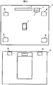
- FIG. 2 is a schematic diagram exemplarily showing spaces (living room r1 and bedroom r2) in which the information processing system 10 is configured.
- the information processing device 4 specifies acoustic apparatuses 3A to 3F to which contents are to be distributed.
- the information processing program, and the information processing system 10 disposed positions of the acoustic apparatuses to which contents are to be distributed are specified, and channel setting of these acoustic apparatuses is performed.
- the information processing system 10 includes an audio player 1, an AV receiver 2, a plurality of acoustic apparatuses 3A to 3F, and the information processing device 4.
- the information processing system 10 is in an indoor room having a plurality of spaces, for example, and outputs contents (music) reproduced by the audio player 1 from one acoustic apparatus or the plurality of acoustic apparatuses 3A to 3F.
- the plurality of acoustic apparatuses 3A to 3F can be moved within one space (room), or to another space. In other words, the plurality of acoustic apparatuses 3A to 3F are not always disposed in the same positions of the same space.
- the information processing system 10 specifies the acoustic apparatuses 3A to 3F disposed in a user-desired space and configures the acoustic apparatuses 3A to 3F to output suitable contents. Through user's operation of the information processing device 4, the information processing system 10 estimates a position of the space in which an acoustic apparatus disposed in the user-desired space, among the plurality of acoustic apparatuses 3A to 3F, is located.
- the audio player 1 is an apparatus for reproducing contents, e.g., a CD player or a DVD player.
- the audio player 1 is disposed in a living room r1, as shown in FIG. 2 .
- the audio player 1 is connected to the AV receiver 2, with wireless or wired communication.
- the audio player 1 transmits the reproduced contents to the AV receiver 2. Note that, it is not limited to the example in which the audio player 1 is disposed in the living room r1.
- the audio player 1 may be disposed in a bedroom r2.
- the information processing system 10 may include a plurality of audio players 1.
- the AV receiver 2 constructs a wireless LAN.
- the AV receiver 2 is connected to the audio player 1, the plurality of acoustic apparatuses 3A to 3F, and the information processing device 4 through the wireless LAN, for example.
- the AV receiver 2 which is located in the living room r1, is disposed near a television 5. Note that, it is not limited to the example in which the AV receiver 2 is disposed near the television 5.
- the AV receiver 2 may be disposed in an indoor room such as the bedroom r2.
- the AV receiver 2 may download contents (e.g., Internet radio) from a contents server through the Internet, for example. Further, the AV receiver 2 may be connected to the plurality of acoustic apparatuses 3A to 3F through a LAN cable. Further, the AV receiver 2 may have a function of the audio player 1.
- contents e.g., Internet radio
- the AV receiver 2 may be connected to the plurality of acoustic apparatuses 3A to 3F through a LAN cable. Further, the AV receiver 2 may have a function of the audio player 1.
- the plurality of acoustic apparatuses 3A to 3F are apparatuses having a speaker or a speaker function, for example.
- the plurality of acoustic apparatuses 3A to 3F are disposed in a plurality of different indoor spaces such as the living room r1 and the bedroom r2.
- the plurality of acoustic apparatuses 3A to 3F output sounds based on a signal outputted from the AV receiver 2.
- the plurality of acoustic apparatuses 3A to 3F are connected to the AV receiver 2, wirelessly or through a wire.
- the information processing device 4 is a portable mobile terminal such as a smart phone. By using a dedicated application that is downloaded into the information processing device 4 in advance, a user performs transmission and reception of information between the AV receiver 2 and the information processing device 4.
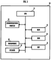
- FIG. 3 is a block diagram showing a configuration of each acoustic apparatus.
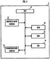
- FIG. 4 is a block diagram showing a configuration of the AV receiver 2.
- a first acoustic apparatus 3A, a second acoustic apparatus 3B, a third acoustic apparatus 3C, and a fourth acoustic apparatus 3D are disposed in the living room r1, as shown in FIG. 2 .
- the first acoustic apparatus 3A, the second acoustic apparatus 3B, the third acoustic apparatus 3C, and the fourth acoustic apparatus 3D each are disposed in different positions of the living room r1.
- a fifth acoustic apparatus 3E and a sixth acoustic apparatus 3F are disposed in the bedroom r2.
- the fifth acoustic apparatus 3E and the sixth acoustic apparatus 3F each are disposed in different positions of the bedroom r2. Note that, for the plurality of acoustic apparatuses 3A to 3F, the number of acoustic apparatuses and the disposed positions are not limited to the example shown in the present embodiment.
- the first acoustic apparatus 3A includes a CPU 31, a communications portion 32, a RAM 33, a ROM 34, and a speaker 35. Besides, the first acoustic apparatus 3A further includes a microphone 36.
- the CPU 31 controls the communications portion 32, the RAM 33, the ROM 34, the speaker 35, and the microphone 36.
- the communications portion 32 is a wireless communications portion according to Wi-Fi standards, for example.
- the communications portion 32 communicates with the AV receiver 2 through a router equipped with wireless access points. Similarly, the communications portion 32 can communicate with the information processing device 4.
- the ROM 34 is a storage medium.
- the ROM 34 stores a program for operating the CPU 31.
- the CPU 31 reads the program, which is stored in the ROM 34, into the RAM 33 to execute it, thereby performing various kinds of processing.
- the speaker 35 has a D/A converter that converts a digital audio signal into an analog audio signal, and an amplifier that amplifies the audio signal.
- the speaker 35 outputs a sound (e.g., music or the like) based on a signal inputted from the AV receiver 2 through the communications portion 32.
- the microphone 36 receives an estimation signal (e.g., a test sound) outputted from the information processing device 4.
- the microphone 36 collects the test sound serving as the estimation signal outputted from the information processing device 4.
- the CPU 31 outputs a beep sound as a response signal. Note that, the response signal is outputted from the speaker 35.
- the response signal is not limited to only a test sound.
- the CPU 31 may transmit the response signal to the information processing device 4 as data, directly or through the communications portion 32. Further, as the response signal, light or both the test sound and light may be employed. In this case, the first acoustic apparatus 3A has a light emitting element such as an LED. The CPU 31 causes the light emitting element to emit light as the response signal.
- the AV receiver 2 includes a CPU 21, a contents input portion 22, a communications portion 23, a DSP 24, a ROM 25, and a RAM 26.
- the CPU 21 controls the contents input portion 22, the communications portion 23, the DSP 24, the ROM 25, and the RAM 26.
- the contents input portion 22 communicates with the audio player 1, wirelessly or through a wire.
- the contents input portion 22 obtains contents from the audio player 1.
- the communications portion 23 is a wireless communications portion according to Wi-Fi standards, for example.
- the communications portion 23 communicates with each of the plurality of acoustic apparatuses 3A to 3F through a router equipped with wireless access points. Note that, if the AV receiver 2 has a router function, the communications portion 23 communicates with each of the plurality of acoustic apparatuses 3A to 3F, directly.
- the DSP 24 applies various kinds of signal processing on the signal inputted to the contents input portion 22.
- the DSP 24 decodes the encoded data to perform the signal processing such as extracting an audio signal.
- the ROM 25 is a storage medium.
- the ROM 25 stores a program for operating the CPU 21.
- the CPU 21 reads the program, which is stored in the ROM 25, into the RAM 26 to execute it, thereby performing various kinds of processing.
- the ROM 25 stores information on the plurality of acoustic apparatuses 3A to 3F.
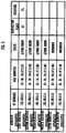
- FIG. 5 is a correspondence table showing an example of the information on the plurality of acoustic apparatuses 3A to 3F, which is stored in the ROM 25.
- Each of the plurality of acoustic apparatuses 3A to 3F is mutually associated with information such as an IP address, a MAC Address, a disposition place (disposed position), a channel, and stored.
- the communications portion 23 receives data from the information processing device 4.
- the contents input portion 22 obtains contents of the audio player 1 based on the received data.
- the communications portion 23 transmits an audio data to each of the plurality of acoustic apparatuses 3A to 3F, based on the contents received from the audio player 1 through the content input portion 22.
- the communications portion 23 performs transmission and reception of data with the information processing device 4.
- the information processing device 4 transmits a start notification to the AV receiver 2.
- the communications portion 23 receives the start notification that is transmitted from the information processing device 4.
- the communications portion 23 transmits a sound-collection start notification to the plurality of acoustic apparatuses 3A to 3F such that microphones 36 of the plurality of acoustic apparatuses 3A to 3F turn into a sound-collection state.
- the information processing device 4 transmits an end notification to the AV receiver 2.
- the communications portion 23 receives the end notification from the information processing device 4.
- the communications portion 23 transmits a sound-collection end notification to each of the plurality of acoustic apparatuses 3A to 3F such that the microphone 36 of each of the plurality of acoustic apparatuses 3A to 3F turns into a sound-collection stop state.
- a corresponding one of inherent IP addresses is assigned to each of the first acoustic apparatus 3A, the second acoustic apparatus 3B, the third acoustic apparatus 3C, the fourth acoustic apparatus 3D, the fifth acoustic apparatus 3E, and the sixth acoustic apparatus 3F.
- the IP addresses of the first acoustic apparatus 3A, the second acoustic apparatus 3B, the third acoustic apparatus 3C, the fourth acoustic apparatus 3D, the fifth acoustic apparatus 3E, and the sixth acoustic apparatus 3F are assigned by the AV receiver 2.
- the IP address of the first acoustic apparatus 3A, the second acoustic apparatus 3B, the third acoustic apparatus 3C, the fourth acoustic apparatus 3D, the fifth acoustic apparatus 3E, and the sixth acoustic apparatus 3F may be assigned by a router or the like.
- first acoustic apparatus 3A, the second acoustic apparatus 3B, the third acoustic apparatus 3C, the fourth acoustic apparatus 3D, the fifth acoustic apparatus 3E, and the sixth acoustic apparatus 3F each have a corresponding one of MAC addresses serving as individual identification information.
- the individual identification information may be any other identification information such as a serial number or an ID number.
- the IP addresses and the MAC addresses are previously associated with the plurality of acoustic apparatuses 3A to 3F one by one. Information on the association is stored in the AV receiver 2.
- the information processing device 4 is a portable mobile terminal such as a smart phone, for example.
- FIG. 6 is a block diagram showing a configuration of the information processing device 4.
- the information processing device 4 includes a CPU 40, a storage portion 41, a display portion 42, an output portion 43, a reception portion 44, a position specifying portion 45, a channel allocation portion 46, and a RAM 47. Further, in addition to the above-mentioned configuration, the information processing device 4 has a function and a configuration provided in a smart phone.
- the information processing devices 4 may be a user operable device such as a tablet, a smart watch, or a PC.
- the CPU40 reads the program, which is stored in the storage portion 41, into the RAM 47 to execute it, thereby performing various kinds of processing.
- the output portion 43 transmits an estimation signal for estimating disposed positions of the plurality of acoustic apparatuses 3A to 3F, which are located in a predetermined space, in the space, and transmits a detection signal to the acoustic apparatuses that have received the estimation signal.
- the output portion 43 has a speaker, a light emitting element, an infrared transmitter, an antenna, or the like, and can output a sound, light, infrared rays, or a signal.
- the output portion 43 outputs a sound, e.g., a beep sound from the speaker as the estimation signal.
- the output portion 43 outputs the beep sound large enough to be collected by only the plurality of acoustic apparatuses (e.g., the first acoustic apparatus 3A, the second acoustic apparatus 3B, the third acoustic apparatus 3C, and the fourth acoustic apparatus 3D) disposed in the predetermined space (e.g., living room r1).
- the acoustic apparatus e.g., the first acoustic apparatus 3A, the second acoustic apparatus 3B, the third acoustic apparatus 3C, and the fourth acoustic apparatus 3D
- the estimation signal is not limited to only a sound, but may be light, infrared rays, or the like.
- the output portion 43 may cause the light emitting element to emit light. Further, in the case where the estimation signal is infrared rays, the output portion 43 outputs infrared rays from the infrared transmitter.
- the output portion 43 outputs a detection signal to the plurality of acoustic apparatuses (e.g., the first acoustic apparatus 3A, the second acoustic apparatus 3B, the third acoustic apparatus 3C, and the fourth acoustic apparatus 3D). More specifically, the output portion 43 outputs the estimation signal to the acoustic apparatuses (e.g., the first acoustic apparatus 3A, the second acoustic apparatus 3B, the third acoustic apparatus 3C, and the 4th acoustic apparatus 3D) to be subjected to the estimation process, directly or through the AV receiver 2. The output portion 43 transmits the detection signal to a user-desired acoustic apparatus (e.g., the first acoustic apparatus 3A), directly or through the AV receiver 2.
- a user-desired acoustic apparatus e.g., the first acoustic apparatus 3A
- the output portion 43 transmits a start notification for announcing a start of estimation processing and an end notification for announcing an end of the estimation processing to the plurality of acoustic apparatuses 3A to 3F, directly or through the AV receiver 2.
- the plurality of acoustic apparatuses 3A to 3F each set the microphone 36 in the sound-collection state or the sound-collection stop state.
- the storage portion 41 stores various kinds of programs to be executed by the CPU 40. Further, the storage portion 41 stores disposition data indicating disposed positions of the plurality of acoustic apparatuses 3A to 3F in the space.
- the disposition data is data in which the plurality of acoustic apparatuses 3A to 3F, the spaces, and the disposed positions are associated with one another. By allocation processing, the plurality of acoustic apparatuses 3A to 3F each are associated with a corresponding one of the spaces in which the plurality of acoustic apparatuses 3A to 3F are disposed, and stored in the storage portion 41.
- the storage portion 41 stores disposition data in which the first acoustic apparatus 3A, the second acoustic apparatus 3B, the third acoustic apparatus 3C, and the fourth acoustic apparatus 3D, which are disposed in the living room r1, are associated with the living room r1. Further, the storage portion 41 stores disposition data in which the fifth acoustic apparatus 3E and the sixth acoustic apparatus 3F, which are disposed in the bedroom r2, are associated with the bedroom r2.
- the disposed positions are information indicating positions of the living room r1 in which the first acoustic apparatus 3A, the second acoustic apparatus 3B, the third acoustic apparatus 3C, and the fourth acoustic apparatus 3D are disposed.
- the plurality of acoustic apparatuses 3A to 3F each are associated with a corresponding one of the disposed positions of the plurality of acoustic apparatuses 3A to 3F, and stored in the storage portion 41.
- the display portion 42 has a screen, e.g., an LCD (Liquid Crystal Display), for displaying an application downloaded by the information processing device 4.
- a screen e.g., an LCD (Liquid Crystal Display)
- LCD Liquid Crystal Display
- a user can tap, slide, or the like on the screen to operate the application.
- the display portion 42 displays a layout drawing based on the disposition data.
- FIG. 7 is an explanatory view showing an example of the layout drawing displayed on the display portion 42.
- a correspondence table is displayed on an upper part of the screen in the display portion 42.
- the first acoustic apparatus 3A, the second acoustic apparatus 3B, the third acoustic apparatus 3C, and the fourth acoustic apparatus 3D which are disposed in the living room r1
- a simplified diagram (layout drawing) simulating the living room r1 is displayed on a lower part of the screen.
- the layout drawing displays disposition places A1 to A4 indicating the disposed positions of the acoustic apparatuses. Accordingly, a user operates the screen such that the first acoustic apparatus 3A, the second acoustic apparatus 3B, the third acoustic apparatus 3C, and the fourth acoustic apparatus 3D correspond to the disposition places A1 to A4 one by one, so that the first acoustic apparatus 3A, the second acoustic apparatus 3B, the third acoustic apparatus 3C and the fourth acoustic apparatus 3D are associated with the disposition places.
- the reception portion 44 which is constituted by a touch panel, receives a corresponding one of the disposed positions of the first acoustic apparatus 3A, the second acoustic apparatus 3B, the third acoustic apparatus 3C, and the fourth acoustic apparatus 3D.
- a user determines which acoustic apparatus is the acoustic apparatus (e.g., the first acoustic apparatus 3A) outputting the sound.
- the user selects, on the screen, where in the disposition places A1 to A4 the acoustic apparatus (e.g., the first acoustic apparatus 3A) outputting the sound is located.
- the acoustic apparatuses 3A to 3F each are displayed line by line, as shown in FIG. 7 .
- the user selects any one of the disposition places A1 to A4 from a pulldown list or the like.
- the reception portion 44 receives a center position. More specifically, when a user touches any of the layout drawing displayed on the lower part of the screen shown in FIG. 7 , the reception portion 44 receives the center position.
- the position specifying portion 45 allocates the disposed position, which has been received by the reception portion 44, to any one of the plurality of acoustic apparatuses 3A to 3F included in the disposition data, and causes the storage portion 41 to store the disposed position that has been allocated to the disposition data.
- the disposition places A1 to A4 which have been received by the reception portion 44, of the first acoustic apparatus 3A, the second acoustic apparatus 3B, the third acoustic apparatus 3C, and the fourth acoustic apparatus 3D each are allocated to a column of disposition shown in FIG. 5 .
- the disposition data in which the first acoustic apparatus 3A, the second acoustic apparatus 3B, the third acoustic apparatus 3C, and the fourth acoustic apparatus 3D each are associated with a corresponding one of the allocated disposition places A1 to A4 is stored in the storage portion 41.
- the channel allocation portion 46 allocates a channel to each of the plurality of acoustic apparatuses (e.g., the first acoustic apparatus 3A, the second acoustic apparatus 3B, the third acoustic apparatus 3C, and the fourth acoustic apparatus 3D), in correspondence to the center position that has been received by the reception portion 44.
- a first center position is a center position newly received by the reception portion 44
- a second center position is a center position stored in the storage portion 41. If the first center position and the second center position are different from each other, the channel allocation portion 46 will allocate a channel, which corresponds to the first center position, to each of the plurality of acoustic apparatuses (e.g., the first acoustic apparatus 3A, the second acoustic apparatus 3B, the third acoustic apparatus 3C, and the fourth acoustic apparatus 3D).
- the center position, which is received by the reception portion 44 is stored in the storage portion 41.
- the information processing device 4 is preferably configured such that contents of the channel are transmitted to the AV receiver 2.
- the center position which is received by the reception portion 44, is stored in the storage portion 41.
- a place at which a television 5 is disposed can be defined as a center position in the living room r1, for example.
- the information processing device 4 will set a channel of the acoustic apparatus to a channel FL.
- the AV receiver 2 will sets a channel of the acoustic apparatus to a channel FR.
- a channel of the acoustic apparatus will be set to a channel SL. Further, if an acoustic apparatus is disposed on a rear right-hand side, a channel of the acoustic apparatus will be set to a channel SR.
- a user can set a position of television 5 to the center position. Accordingly, when the information processing system 10 is used at the next time, it is not necessary for a user to input a center position again, because the storage portion 41 stores the center position. As a result, in the information processing device 4 and the information processing system 10 of the present embodiment, the time required for channel setting can be shortened.
- the information processing device 4 and the information processing system 10 of the present embodiment can specify the acoustic apparatuses (e.g., the first acoustic apparatus 3A, the second acoustic apparatus 3B, the third acoustic apparatus 3C, and the fourth acoustic apparatus 3D) disposed in a user-desired space, e.g., the living room r1. Further, the information processing device 4 and the information processing system of the present embodiment can detect disposed positions of the specified acoustic apparatuses (e.g., the first acoustic apparatus 3A, the second acoustic apparatus 3B, the third acoustic apparatus 3C, and the fourth acoustic apparatus 3D).
- the specified acoustic apparatuses e.g., the first acoustic apparatus 3A, the second acoustic apparatus 3B, the third acoustic apparatus 3C, and the fourth acoustic apparatus 3D.
- the information processing device 4 and the information processing system 10 of the present embodiment can specify disposed positions of the acoustic apparatuses 3A to 3F more simply. Further, in the information processing device 4 and the information processing system 10 of the present embodiment, the center position is specified to enable channel setting of the specified acoustic apparatuses (e.g., the first acoustic apparatus 3A, the second acoustic apparatus 3B, the third acoustic apparatus 3C, and the fourth acoustic apparatus 3D) as necessary.
- the specified acoustic apparatuses e.g., the first acoustic apparatus 3A, the second acoustic apparatus 3B, the third acoustic apparatus 3C, and the fourth acoustic apparatus 3D
- the information processing device 4 can achieve various kinds of functions, mentioned above, by using an information processing program executed by the CPU 40 existed in the information processing device 4.
- the information processing program By executing the information processing program, disposed positions of the acoustic apparatuses 3A to 3F can be specified more simply.
- FIG. 8 is a flowchart showing the operation of the information processing system 10.
- the storage portion 24 of the AV receiver 2 stores data in which each of the plurality of acoustic apparatuses 3A to 3F is associated with an IP address and a MAC address corresponding to each of the plurality of acoustic apparatuses 3A to 3F.
- the information processing device 4 can receive the above-mentioned data.
- a user carries the information processing device 4 to operate the information processing device 4 at the center of living room r1, as shown in FIG. 2 .
- the user can watch the correspondence table shown in FIG. 5 on the screen.
- a user-desired center position is set to the position at which the television 5 is disposed.
- the information processing system 10 performs estimation processing that estimates an acoustic apparatus to be subjected to the estimation process, among the plurality of acoustic apparatuses 3A to 3F (Step S11). For the acoustic apparatus that have determined to be subjected to the estimation process among the plurality of acoustic apparatuses 3A to 3F (Step S12: YES), e.g., the first acoustic apparatus 3A, the second acoustic apparatus 3B, the third acoustic apparatus 3C, and the fourth acoustic apparatus 3D, the information processing system 10 performs position specifying processing (Step S13).
- the information processing system 10 receives the center position, and performs channel setting processing (Step S14).
- Step S12 determines whether the acoustic apparatuses determined not to be subjected to the estimation process (Step S12: NO), e.g., the fifth acoustic apparatus 3E and the sixth acoustic apparatus 3F.
- the information processing system 10 completes the processing (shifted to RETURN).
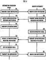
- FIG. 9 is a flowchart showing operations of the information processing device 4 and each of the acoustic apparatuses 3A to 3F in the estimation processing of the information processing system 10.
- a user operates an application on the screen to set the information processing system 10 in a processing start state.
- the output portion 43 of the information processing device 4 transmits a start notification to the plurality of acoustic apparatuses 3A to 3F through the AV receiver 2 (Step S21).
- the information processing device 4 sets a timeout (e.g., 5 seconds) for stopping the start notification in advance.
- a timeout e.g., 5 seconds
- Each of the plurality of acoustic apparatuses 3A to 3F turns the microphone 36 into a sound-collection possible state.
- Each of the plurality of acoustic apparatuses 3A to 3F announces a sound-collection preparing notification to the information processing device 4 through the AV receiver 2 (Step S23).
- the sound-collection preparing notification indicates that the microphone 36 is set in the sound-collection possible state.
- the information processing device 4 receives the sound-collection preparing notification (Step S24)
- the information processing device 4 transmits an estimation signal (test sound) from the output portion 43 (Step S25).
- the first acoustic apparatus 3A, the second acoustic apparatus 3B, the third acoustic apparatus 3C, and the fourth acoustic apparatus 3D collect the estimation signal (Step S26).
- the first acoustic apparatus 3A, the second acoustic apparatus 3B, the third acoustic apparatus 3C, and the fourth acoustic apparatus 3D transmit an estimation-signal receiving notification to the information processing device 4, directly or through the AV receiver 2 (Step S27).
- the estimation-signal receiving notification indicates that the estimation signal has been collected.
- the information processing device 4 receives the estimation-signal receiving notification (Step S28). At this time, the information processing device 4 causes the display portion 42 to display the first acoustic apparatus 3A, the second acoustic apparatus 3B, the third acoustic apparatus 3C, and the fourth acoustic apparatus 3D, which have received the estimation signal. According to the timeout or user's manual operation, the information processing device 4 stops the estimation signal (Step S29). The information processing device 4 announces an end notification to the plurality of acoustic apparatuses 3A to 3F through the AV receiver 2 (Step S30). The plurality of acoustic apparatuses 3A to 3F receive the end notification (Step S31), and then causes the sound-collection state of the microphone 36 in the information processing system 10 to be stopped.
- the fifth acoustic apparatus 3E and the sixth acoustic apparatus 3F which are disposed in the bedroom r2, do not collect the estimation signal.
- the fifth acoustic apparatus 3E and the sixth acoustic apparatus 3F notify the information processing device 4, through the AV receiver 2, that the estimation signal is not collected. Note that, for the acoustic apparatuses (herein, the fifth acoustic apparatus 3E and the sixth acoustic apparatus 3F) in which sound-collection is not performed, it is not necessary to notify the information processing device 4 that the sound-collection is not performed, because the information processing device 4 specifies only the acoustic apparatuses that have collected the estimation signal.
- a user can easily specify acoustic apparatuses in the space as necessary, because only the acoustic apparatuses that have received the estimation signal are subjected to the estimation process.
- a disposed position of an acoustic apparatus can be specified more simply.
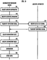
- FIG. 10 is a flowchart showing operations of the information processing device 4 and the acoustic apparatus (herein, the first acoustic apparatus 3A) in the position specifying processing of the information processing system 10.
- a user selects any of the first acoustic apparatus 3A, the second acoustic apparatus 3B, the third acoustic apparatus 3C, and the fourth acoustic apparatus 3D, which are shown in FIG. 7 (Step S41). More specifically, a section or a row of acoustic apparatuses, which is to be set by a user, is selected.
- the reception portion 44 receives an input of the first acoustic apparatus 3A selected by a user, for example (Step S42).
- the output portion 43 of the information processing device 4 transmits through the AV receiver 2 the detection signal to the first acoustic apparatus 3A received by reception portion 44 (Step S43).
- the first acoustic apparatus 3A receives the detection signal (Step S44), and outputs a response signal (Step S45).
- the first acoustic apparatus 3A is disposed on the left-hand side of the television 5.
- the first acoustic apparatus 3A is disposed on the front left-hand side of the user.
- the user can select the disposition place A1 from a pulldown list such that a disposed position of the first acoustic apparatus 3A corresponds to the disposition place A1 (Step S46).
- the reception portion 44 of the information processing device 4 receives that the disposed position of the first acoustic apparatus 3A corresponds to the disposition place A1 (Step S47).
- the first acoustic apparatus 3A is associated with the disposition place A1 (Step S48).
- the storage portion 41 stores data in which the first acoustic apparatus 3A is associated with the disposition place A1 (Step S49).
- a user can easily specify the acoustic apparatus outputting the beep sound, and can use the information processing device 4 to specify a disposed position of each acoustic apparatus.
- the information processing method of the present embodiment can easily specify a position of the acoustic apparatus to be subjected to the estimation process, among the plurality of acoustic apparatuses 3A to 3F.
- the information processing method of the embodiment can specify a disposed position of an acoustic apparatus more simply.
- FIG. 11 is a flowchart showing an operation of the information processing device 4 in the channel setting processing of the information processing system 10.
- the storage portion 41 stores a temporary center position (second center position) in advance in the storage portion 41.
- the reception portion 44 receives a center position selected by a user (Step S51).
- the center position is set to a position at which the television 5, shown in FIG. 2 , is disposed.
- a television 5 side is defined as a front side
- a wall side opposite to the front side where the television 5 is disposed is defined as a rear side.
- both sides centered on the television 5 toward the front side are defined as a right-hand side and a left-hand side, respectively.
- the center position received by the reception portion 44 is stored in the storage portion 41 as a first center position (Step S52).
- the channel allocation portion 46 will allocate a channel to each of the first acoustic apparatus 3A, the second acoustic apparatus 3B, the third acoustic apparatus 3C, and the fourth acoustic apparatus 3D (Step S54).
- the channel allocation portion 46 causes the storage portion 41 to store the first center position as the second center position (Step S55).
- channels of the acoustic apparatuses to be subjected to the estimation process e.g., the first acoustic apparatus 3A, the second acoustic apparatus 3B, the third acoustic apparatus 3C, and the fourth acoustic apparatus 3D are allocated.
- the information processing device 4 can set channels of the plurality of acoustic apparatuses, efficiently and suitably.
- the information processing device 4 may use an existing camera function to record a video or a photograph of the space, thereby analyzing the video data or the photograph to specify disposed positions of the plurality of acoustic apparatuses 3A to 3F.
- the response signal may be a sound.
- a user can detect the disposition place easily.
- the response signal is a sound, a user can specify acoustic apparatuses more easily.
Landscapes
- Engineering & Computer Science (AREA)
- Physics & Mathematics (AREA)
- Acoustics & Sound (AREA)
- Signal Processing (AREA)
- Multimedia (AREA)
- Health & Medical Sciences (AREA)
- General Health & Medical Sciences (AREA)
- Otolaryngology (AREA)
- Stereophonic System (AREA)
- Circuit For Audible Band Transducer (AREA)
Abstract
Description
- One embodiment of the present invention relates to an information processing device, an information processing system, an information processing program, and an information processing method, and especially, is an information processing device, an information processing system, an information processing program, and an information processing method that specify a disposed position of an acoustic apparatus.
- Conventionally, there is a multichannel audio system that has a plurality of channels and includes speakers corresponding to the number of these channels (e.g., Patent Literature 1).
- In the multichannel audio system, a signal processing unit of an amplifier device performs channel allocation processing in order to construct a multichannel reproduction environment. Thus, the multichannel audio system determines where a plurality (nine) of speakers, which are to be used, each are located (determine positions of the plurality of speakers).
- In the channel allocation processing, a user disposes microphones on left, right, front, and rear sides of a viewing position, and each microphone collects a measurement sound outputted from each speaker. The sound collection data, which is collected by the microphones, is used to measure a position of each microphone and a distance from each speaker. Based on these distances, the multichannel audio system determines where the plurality of speakers each are located.
- Patent Literature 1: International publication No.
2008/126161 - To specify positions of a plurality of speakers (acoustic apparatuses), the multichannel audio system (information processing device) in
Patent Literature 1 uses microphones. In the multichannel audio system, four measurements are required for each of the plurality of speakers. Further, the multichannel audio system employs one microphone, and a user sequentially disposes the microphone at four points, i.e., the front, rear, left and right sides of a viewing position. In such a multichannel audio system, a number of measurements are required. In addition to this, a user needs to move the microphone. Therefore, it takes time to specify positions of the plurality of speakers. As a result, in the multichannel audio system ofPatent Literature 1, construction work of multichannel reproduction environment is likely to be complicated. - Accordingly, an object of the present invention is to provide an information processing device, an information processing system, an information processing program, and an information processing method that can specify a disposed position of an acoustic apparatus more simply.
- An information processing device according to one embodiment of the present invention includes an output portion that outputs a detection signal to a plurality of acoustic apparatuses; a reception portion that receives a disposed position of each of the plurality of acoustic apparatuses, based on a response signal outputted from the plurality of acoustic apparatuses that have received the detection signal; a storage portion that stores disposition data indicating disposed positions of the plurality of acoustic apparatuses; and a position specifying portion that allocates the disposed position received by the reception portion to any one of the plurality of acoustic apparatuses included in the disposition data, and causes the storage portion to store the disposed position allocated to the disposition data.
- According to one embodiment of the present invention, a disposed position of an acoustic apparatus can be specified more simply.
-
-
FIG. 1 is a block diagram showing a configuration of an information processing system. -
FIG. 2 is a schematic view exemplarily showing spaces in which the information processing system is configured. -
FIG. 3 is a block diagram showing a configuration of an acoustic apparatus. -
FIG. 4 is a block diagram showing a configuration of an AV receiver. -
FIG. 5 is a correspondence table exemplarily showing information on a plurality of acoustic apparatuses. -
FIG. 6 is a block diagram showing a configuration of an information processing device. -
FIG. 7 is an explanatory view exemplarily showing a layout drawing displayed on a display portion. -
FIG. 8 is a flowchart showing an operation of the information processing system. -
FIG. 9 is a flowchart showing operations of the information processing device and each acoustic apparatus in estimation processing of the information processing system. -
FIG. 10 is a flowchart showing operations of the information processing device and the acoustic apparatus in position specifying processing of the acoustic apparatus in the information processing system. -
FIG. 11 is a flowchart showing an operation of the information processing device in channel allocation processing of the information processing system. - An
information processing device 4, an information processing program, and aninformation processing system 10 according to one embodiment of the present invention will be described with reference to the drawings. - First, the
information processing system 10 will be described with reference toFIGS. 1 and2 .FIG. 1 is a block diagram showing a configuration of theinformation processing system 10 according to one embodiment of the present invention.FIG. 2 is a schematic diagram exemplarily showing spaces (living room r1 and bedroom r2) in which theinformation processing system 10 is configured. - In the
information processing device 4, the information processing program, and theinformation processing system 10 of the present embodiment, theinformation processing device 4 specifiesacoustic apparatuses 3A to 3F to which contents are to be distributed. In theinformation processing device 4, the information processing program, and theinformation processing system 10, disposed positions of the acoustic apparatuses to which contents are to be distributed are specified, and channel setting of these acoustic apparatuses is performed. - As shown in
FIG. 1 , theinformation processing system 10 includes anaudio player 1, anAV receiver 2, a plurality ofacoustic apparatuses 3A to 3F, and theinformation processing device 4. Theinformation processing system 10 is in an indoor room having a plurality of spaces, for example, and outputs contents (music) reproduced by theaudio player 1 from one acoustic apparatus or the plurality ofacoustic apparatuses 3A to 3F. The plurality ofacoustic apparatuses 3A to 3F can be moved within one space (room), or to another space. In other words, the plurality ofacoustic apparatuses 3A to 3F are not always disposed in the same positions of the same space. Theinformation processing system 10 specifies theacoustic apparatuses 3A to 3F disposed in a user-desired space and configures theacoustic apparatuses 3A to 3F to output suitable contents. Through user's operation of theinformation processing device 4, theinformation processing system 10 estimates a position of the space in which an acoustic apparatus disposed in the user-desired space, among the plurality ofacoustic apparatuses 3A to 3F, is located. - The
audio player 1 is an apparatus for reproducing contents, e.g., a CD player or a DVD player. In theinformation processing system 10 of the present embodiment, theaudio player 1 is disposed in a living room r1, as shown inFIG. 2 . Theaudio player 1 is connected to theAV receiver 2, with wireless or wired communication. Theaudio player 1 transmits the reproduced contents to theAV receiver 2. Note that, it is not limited to the example in which theaudio player 1 is disposed in the living room r1. Theaudio player 1 may be disposed in a bedroom r2. Further, theinformation processing system 10 may include a plurality ofaudio players 1. - By using a router with a wireless access point function, the
AV receiver 2 constructs a wireless LAN. TheAV receiver 2 is connected to theaudio player 1, the plurality ofacoustic apparatuses 3A to 3F, and theinformation processing device 4 through the wireless LAN, for example. - For instance, as shown in
FIG. 2 , theAV receiver 2, which is located in the living room r1, is disposed near atelevision 5. Note that, it is not limited to the example in which theAV receiver 2 is disposed near thetelevision 5. TheAV receiver 2 may be disposed in an indoor room such as the bedroom r2. - Note that, it is not limited to the example in which the
AV receiver 2 obtains contents from theaudio player 1. TheAV receiver 2 may download contents (e.g., Internet radio) from a contents server through the Internet, for example. Further, theAV receiver 2 may be connected to the plurality ofacoustic apparatuses 3A to 3F through a LAN cable. Further, theAV receiver 2 may have a function of theaudio player 1. - The plurality of
acoustic apparatuses 3A to 3F are apparatuses having a speaker or a speaker function, for example. The plurality ofacoustic apparatuses 3A to 3F are disposed in a plurality of different indoor spaces such as the living room r1 and the bedroom r2. The plurality ofacoustic apparatuses 3A to 3F output sounds based on a signal outputted from theAV receiver 2. The plurality ofacoustic apparatuses 3A to 3F are connected to theAV receiver 2, wirelessly or through a wire. - The
information processing device 4 is a portable mobile terminal such as a smart phone. By using a dedicated application that is downloaded into theinformation processing device 4 in advance, a user performs transmission and reception of information between theAV receiver 2 and theinformation processing device 4. - Next, the
AV receiver 2, the plurality ofacoustic apparatuses 3A to 3F, and theinformation processing device 4 according to the present embodiment will be described in detail.FIG. 3 is a block diagram showing a configuration of each acoustic apparatus.FIG. 4 is a block diagram showing a configuration of theAV receiver 2. - Among the plurality (six) of
acoustic apparatuses 3A to 3F, a firstacoustic apparatus 3A, a secondacoustic apparatus 3B, a thirdacoustic apparatus 3C, and a fourthacoustic apparatus 3D are disposed in the living room r1, as shown inFIG. 2 . The firstacoustic apparatus 3A, the secondacoustic apparatus 3B, the thirdacoustic apparatus 3C, and the fourthacoustic apparatus 3D each are disposed in different positions of the living room r1. Further, among the plurality ofacoustic apparatuses 3A to 3F, a fifthacoustic apparatus 3E and a sixthacoustic apparatus 3F are disposed in the bedroom r2. The fifthacoustic apparatus 3E and the sixthacoustic apparatus 3F each are disposed in different positions of the bedroom r2. Note that, for the plurality ofacoustic apparatuses 3A to 3F, the number of acoustic apparatuses and the disposed positions are not limited to the example shown in the present embodiment. - Now, in
FIG. 3 , the firstacoustic apparatus 3A will be described as an example. Note that, other acoustic apparatuses (the secondacoustic apparatus 3B, the thirdacoustic apparatus 3C, the fourthacoustic apparatus 3D, the fifthacoustic apparatus 3E, and the sixthacoustic apparatus 3F) all have the same configuration and function. The firstacoustic apparatus 3A includes aCPU 31, acommunications portion 32, a RAM 33, aROM 34, and aspeaker 35. Besides, the firstacoustic apparatus 3A further includes amicrophone 36. - The
CPU 31 controls thecommunications portion 32, the RAM 33, theROM 34, thespeaker 35, and themicrophone 36. - The
communications portion 32 is a wireless communications portion according to Wi-Fi standards, for example. Thecommunications portion 32 communicates with theAV receiver 2 through a router equipped with wireless access points. Similarly, thecommunications portion 32 can communicate with theinformation processing device 4. - The
ROM 34 is a storage medium. TheROM 34 stores a program for operating theCPU 31. TheCPU 31 reads the program, which is stored in theROM 34, into the RAM 33 to execute it, thereby performing various kinds of processing. - The
speaker 35 has a D/A converter that converts a digital audio signal into an analog audio signal, and an amplifier that amplifies the audio signal. Thespeaker 35 outputs a sound (e.g., music or the like) based on a signal inputted from theAV receiver 2 through thecommunications portion 32. - The
microphone 36 receives an estimation signal (e.g., a test sound) outputted from theinformation processing device 4. In other words, themicrophone 36 collects the test sound serving as the estimation signal outputted from theinformation processing device 4. When themicrophone 36 collects the test sound, theCPU 31 outputs a beep sound as a response signal. Note that, the response signal is outputted from thespeaker 35. - Note that, the response signal is not limited to only a test sound. The
CPU 31 may transmit the response signal to theinformation processing device 4 as data, directly or through thecommunications portion 32. Further, as the response signal, light or both the test sound and light may be employed. In this case, the firstacoustic apparatus 3A has a light emitting element such as an LED. TheCPU 31 causes the light emitting element to emit light as the response signal. - As shown in
FIG. 4 , theAV receiver 2 includes aCPU 21, acontents input portion 22, acommunications portion 23, aDSP 24, aROM 25, and aRAM 26. - The
CPU 21 controls thecontents input portion 22, thecommunications portion 23, theDSP 24, theROM 25, and theRAM 26. - The
contents input portion 22 communicates with theaudio player 1, wirelessly or through a wire. Thecontents input portion 22 obtains contents from theaudio player 1. - The
communications portion 23 is a wireless communications portion according to Wi-Fi standards, for example. Thecommunications portion 23 communicates with each of the plurality ofacoustic apparatuses 3A to 3F through a router equipped with wireless access points. Note that, if theAV receiver 2 has a router function, thecommunications portion 23 communicates with each of the plurality ofacoustic apparatuses 3A to 3F, directly. - The
DSP 24 applies various kinds of signal processing on the signal inputted to thecontents input portion 22. When receiving encoded data as a signal of contents, theDSP 24 decodes the encoded data to perform the signal processing such as extracting an audio signal. - The
ROM 25 is a storage medium. TheROM 25 stores a program for operating theCPU 21. TheCPU 21 reads the program, which is stored in theROM 25, into theRAM 26 to execute it, thereby performing various kinds of processing. - Further, the
ROM 25 stores information on the plurality ofacoustic apparatuses 3A to 3F.FIG. 5 is a correspondence table showing an example of the information on the plurality ofacoustic apparatuses 3A to 3F, which is stored in theROM 25. Each of the plurality ofacoustic apparatuses 3A to 3F is mutually associated with information such as an IP address, a MAC Address, a disposition place (disposed position), a channel, and stored. - The
communications portion 23 receives data from theinformation processing device 4. Thecontents input portion 22 obtains contents of theaudio player 1 based on the received data. Thecommunications portion 23 transmits an audio data to each of the plurality ofacoustic apparatuses 3A to 3F, based on the contents received from theaudio player 1 through thecontent input portion 22. - Further, the
communications portion 23 performs transmission and reception of data with theinformation processing device 4. When receiving a setting operation or the like from a user, theinformation processing device 4 transmits a start notification to theAV receiver 2. Thecommunications portion 23 receives the start notification that is transmitted from theinformation processing device 4. When receiving the start notification, thecommunications portion 23 transmits a sound-collection start notification to the plurality ofacoustic apparatuses 3A to 3F such thatmicrophones 36 of the plurality ofacoustic apparatuses 3A to 3F turn into a sound-collection state. Furthermore, according to a timeout or a user's operation, theinformation processing device 4 transmits an end notification to theAV receiver 2. Thecommunications portion 23 receives the end notification from theinformation processing device 4. If themicrophone 36 of each of the plurality ofacoustic apparatuses 3A to 3F is in a sound-collection state, thecommunications portion 23 transmits a sound-collection end notification to each of the plurality ofacoustic apparatuses 3A to 3F such that themicrophone 36 of each of the plurality ofacoustic apparatuses 3A to 3F turns into a sound-collection stop state. - By the way, a corresponding one of inherent IP addresses (local addresses) is assigned to each of the first
acoustic apparatus 3A, the secondacoustic apparatus 3B, the thirdacoustic apparatus 3C, the fourthacoustic apparatus 3D, the fifthacoustic apparatus 3E, and the sixthacoustic apparatus 3F. The IP addresses of the firstacoustic apparatus 3A, the secondacoustic apparatus 3B, the thirdacoustic apparatus 3C, the fourthacoustic apparatus 3D, the fifthacoustic apparatus 3E, and the sixthacoustic apparatus 3F are assigned by theAV receiver 2. Note that, the IP address of the firstacoustic apparatus 3A, the secondacoustic apparatus 3B, the thirdacoustic apparatus 3C, the fourthacoustic apparatus 3D, the fifthacoustic apparatus 3E, and the sixthacoustic apparatus 3F may be assigned by a router or the like. - Further, the first
acoustic apparatus 3A, the secondacoustic apparatus 3B, the thirdacoustic apparatus 3C, the fourthacoustic apparatus 3D, the fifthacoustic apparatus 3E, and the sixthacoustic apparatus 3F each have a corresponding one of MAC addresses serving as individual identification information. Note that, the individual identification information may be any other identification information such as a serial number or an ID number. The IP addresses and the MAC addresses are previously associated with the plurality ofacoustic apparatuses 3A to 3F one by one. Information on the association is stored in theAV receiver 2. - The
information processing device 4 is a portable mobile terminal such as a smart phone, for example.FIG. 6 is a block diagram showing a configuration of theinformation processing device 4. Theinformation processing device 4 includes aCPU 40, astorage portion 41, adisplay portion 42, anoutput portion 43, areception portion 44, aposition specifying portion 45, achannel allocation portion 46, and aRAM 47. Further, in addition to the above-mentioned configuration, theinformation processing device 4 has a function and a configuration provided in a smart phone. - Note that, the
information processing devices 4 may be a user operable device such as a tablet, a smart watch, or a PC. - For instance, the CPU40 reads the program, which is stored in the
storage portion 41, into theRAM 47 to execute it, thereby performing various kinds of processing. - The
output portion 43 transmits an estimation signal for estimating disposed positions of the plurality ofacoustic apparatuses 3A to 3F, which are located in a predetermined space, in the space, and transmits a detection signal to the acoustic apparatuses that have received the estimation signal. Theoutput portion 43 has a speaker, a light emitting element, an infrared transmitter, an antenna, or the like, and can output a sound, light, infrared rays, or a signal. In theinformation processing device 4 of the present embodiment, theoutput portion 43 outputs a sound, e.g., a beep sound from the speaker as the estimation signal. Theoutput portion 43 outputs the beep sound large enough to be collected by only the plurality of acoustic apparatuses (e.g., the firstacoustic apparatus 3A, the secondacoustic apparatus 3B, the thirdacoustic apparatus 3C, and the fourthacoustic apparatus 3D) disposed in the predetermined space (e.g., living room r1). Thus, in theinformation processing system 10, only the acoustic apparatus (e.g., the firstacoustic apparatus 3A, the secondacoustic apparatus 3B, the thirdacoustic apparatus 3C, and the fourthacoustic apparatus 3D) that have collected the beep sound are subjected to estimation process. - Note that, the estimation signal is not limited to only a sound, but may be light, infrared rays, or the like. For instance, as the estimation signal, the
output portion 43 may cause the light emitting element to emit light. Further, in the case where the estimation signal is infrared rays, theoutput portion 43 outputs infrared rays from the infrared transmitter. - Furthermore, the
output portion 43 outputs a detection signal to the plurality of acoustic apparatuses (e.g., the firstacoustic apparatus 3A, the secondacoustic apparatus 3B, the thirdacoustic apparatus 3C, and the fourthacoustic apparatus 3D). More specifically, theoutput portion 43 outputs the estimation signal to the acoustic apparatuses (e.g., the firstacoustic apparatus 3A, the secondacoustic apparatus 3B, the thirdacoustic apparatus 3C, and the 4thacoustic apparatus 3D) to be subjected to the estimation process, directly or through theAV receiver 2. Theoutput portion 43 transmits the detection signal to a user-desired acoustic apparatus (e.g., the firstacoustic apparatus 3A), directly or through theAV receiver 2. - Further, the
output portion 43 transmits a start notification for announcing a start of estimation processing and an end notification for announcing an end of the estimation processing to the plurality ofacoustic apparatuses 3A to 3F, directly or through theAV receiver 2. Thus, the plurality ofacoustic apparatuses 3A to 3F each set themicrophone 36 in the sound-collection state or the sound-collection stop state. - The
storage portion 41 stores various kinds of programs to be executed by theCPU 40. Further, thestorage portion 41 stores disposition data indicating disposed positions of the plurality ofacoustic apparatuses 3A to 3F in the space. The disposition data is data in which the plurality ofacoustic apparatuses 3A to 3F, the spaces, and the disposed positions are associated with one another. By allocation processing, the plurality ofacoustic apparatuses 3A to 3F each are associated with a corresponding one of the spaces in which the plurality ofacoustic apparatuses 3A to 3F are disposed, and stored in thestorage portion 41. For instance, thestorage portion 41 stores disposition data in which the firstacoustic apparatus 3A, the secondacoustic apparatus 3B, the thirdacoustic apparatus 3C, and the fourthacoustic apparatus 3D, which are disposed in the living room r1, are associated with the living room r1. Further, thestorage portion 41 stores disposition data in which the fifthacoustic apparatus 3E and the sixthacoustic apparatus 3F, which are disposed in the bedroom r2, are associated with the bedroom r2. - For instance, the disposed positions are information indicating positions of the living room r1 in which the first
acoustic apparatus 3A, the secondacoustic apparatus 3B, the thirdacoustic apparatus 3C, and the fourthacoustic apparatus 3D are disposed. By position specifying processing, the plurality ofacoustic apparatuses 3A to 3F each are associated with a corresponding one of the disposed positions of the plurality ofacoustic apparatuses 3A to 3F, and stored in thestorage portion 41. - The
display portion 42 has a screen, e.g., an LCD (Liquid Crystal Display), for displaying an application downloaded by theinformation processing device 4. A user can tap, slide, or the like on the screen to operate the application. - The
display portion 42 displays a layout drawing based on the disposition data.FIG. 7 is an explanatory view showing an example of the layout drawing displayed on thedisplay portion 42. As shown inFIG. 7 , a correspondence table is displayed on an upper part of the screen in thedisplay portion 42. In the correspondence table, the firstacoustic apparatus 3A, the secondacoustic apparatus 3B, the thirdacoustic apparatus 3C, and the fourthacoustic apparatus 3D, which are disposed in the living room r1, are associated with disposed positions, selected later, and channels. Further, a simplified diagram (layout drawing) simulating the living room r1 is displayed on a lower part of the screen. The layout drawing displays disposition places A1 to A4 indicating the disposed positions of the acoustic apparatuses. Accordingly, a user operates the screen such that the firstacoustic apparatus 3A, the secondacoustic apparatus 3B, the thirdacoustic apparatus 3C, and the fourthacoustic apparatus 3D correspond to the disposition places A1 to A4 one by one, so that the firstacoustic apparatus 3A, the secondacoustic apparatus 3B, the thirdacoustic apparatus 3C and the fourthacoustic apparatus 3D are associated with the disposition places. - For instance, based on the response signal outputted from the plurality of acoustic apparatuses (e.g., the first
acoustic apparatus 3A, the secondacoustic apparatus 3B, the thirdacoustic apparatus 3C, and the fourthacoustic apparatus 3D), thereception portion 44, which is constituted by a touch panel, receives a corresponding one of the disposed positions of the firstacoustic apparatus 3A, the secondacoustic apparatus 3B, the thirdacoustic apparatus 3C, and the fourthacoustic apparatus 3D. For instance, in the case where the response signal is a sound, a user determines which acoustic apparatus is the acoustic apparatus (e.g., the firstacoustic apparatus 3A) outputting the sound. The user selects, on the screen, where in the disposition places A1 to A4 the acoustic apparatus (e.g., the firstacoustic apparatus 3A) outputting the sound is located. On the screen of thedisplay portion 42, theacoustic apparatuses 3A to 3F each are displayed line by line, as shown inFIG. 7 . To each of the firstacoustic apparatus 3A, the secondacoustic apparatus 3B, the thirdacoustic apparatus 3C, and the fourthacoustic apparatus 3D, the user selects any one of the disposition places A1 to A4 from a pulldown list or the like. - Further, the
reception portion 44 receives a center position. More specifically, when a user touches any of the layout drawing displayed on the lower part of the screen shown inFIG. 7 , thereception portion 44 receives the center position. - The
position specifying portion 45 allocates the disposed position, which has been received by thereception portion 44, to any one of the plurality ofacoustic apparatuses 3A to 3F included in the disposition data, and causes thestorage portion 41 to store the disposed position that has been allocated to the disposition data. In other words, by theposition specifying portion 45, the disposition places A1 to A4, which have been received by thereception portion 44, of the firstacoustic apparatus 3A, the secondacoustic apparatus 3B, the thirdacoustic apparatus 3C, and the fourthacoustic apparatus 3D each are allocated to a column of disposition shown inFIG. 5 . The disposition data in which the firstacoustic apparatus 3A, the secondacoustic apparatus 3B, the thirdacoustic apparatus 3C, and the fourthacoustic apparatus 3D each are associated with a corresponding one of the allocated disposition places A1 to A4 is stored in thestorage portion 41. - For the acoustic apparatuses (e.g., the first
acoustic apparatus 3A, the secondacoustic apparatus 3B, the thirdacoustic apparatus 3C, and the fourthacoustic apparatus 3D) to be subjected to the allocation, thechannel allocation portion 46 allocates a channel to each of the plurality of acoustic apparatuses (e.g., the firstacoustic apparatus 3A, the secondacoustic apparatus 3B, the thirdacoustic apparatus 3C, and the fourthacoustic apparatus 3D), in correspondence to the center position that has been received by thereception portion 44. Further, it is assumed that a first center position is a center position newly received by thereception portion 44, and a second center position is a center position stored in thestorage portion 41. If the first center position and the second center position are different from each other, thechannel allocation portion 46 will allocate a channel, which corresponds to the first center position, to each of the plurality of acoustic apparatuses (e.g., the firstacoustic apparatus 3A, the secondacoustic apparatus 3B, the thirdacoustic apparatus 3C, and the fourthacoustic apparatus 3D). The center position, which is received by thereception portion 44, is stored in thestorage portion 41. Note that, theinformation processing device 4 is preferably configured such that contents of the channel are transmitted to theAV receiver 2. - Further, the center position, which is received by the
reception portion 44, is stored in thestorage portion 41. In theinformation processing system 10 of the present embodiment, as shown inFIG. 2 , a place at which atelevision 5 is disposed can be defined as a center position in the living room r1, for example. In theinformation processing system 10 of the present embodiment, if an acoustic apparatus is disposed on a left-hand side toward the center position, theinformation processing device 4 will set a channel of the acoustic apparatus to a channel FL. Further, if an acoustic apparatus is disposed on a right-hand side toward the center position, theAV receiver 2 will sets a channel of the acoustic apparatus to a channel FR. Furthermore, assumed that the center position is located on a front side, if an acoustic apparatus is disposed on a rear left-hand side, a channel of the acoustic apparatus will be set to a channel SL. Further, if an acoustic apparatus is disposed on a rear right-hand side, a channel of the acoustic apparatus will be set to a channel SR. - Furthermore, by operating the
information processing device 4, a user can set a position oftelevision 5 to the center position. Accordingly, when theinformation processing system 10 is used at the next time, it is not necessary for a user to input a center position again, because thestorage portion 41 stores the center position. As a result, in theinformation processing device 4 and theinformation processing system 10 of the present embodiment, the time required for channel setting can be shortened. - The
information processing device 4 and theinformation processing system 10 of the present embodiment can specify the acoustic apparatuses (e.g., the firstacoustic apparatus 3A, the secondacoustic apparatus 3B, the thirdacoustic apparatus 3C, and the fourthacoustic apparatus 3D) disposed in a user-desired space, e.g., the living room r1. Further, theinformation processing device 4 and the information processing system of the present embodiment can detect disposed positions of the specified acoustic apparatuses (e.g., the firstacoustic apparatus 3A, the secondacoustic apparatus 3B, the thirdacoustic apparatus 3C, and the fourthacoustic apparatus 3D). As a result, theinformation processing device 4 and theinformation processing system 10 of the present embodiment can specify disposed positions of theacoustic apparatuses 3A to 3F more simply. Further, in theinformation processing device 4 and theinformation processing system 10 of the present embodiment, the center position is specified to enable channel setting of the specified acoustic apparatuses (e.g., the firstacoustic apparatus 3A, the secondacoustic apparatus 3B, the thirdacoustic apparatus 3C, and the fourthacoustic apparatus 3D) as necessary. - By the way, the
information processing device 4 can achieve various kinds of functions, mentioned above, by using an information processing program executed by theCPU 40 existed in theinformation processing device 4. By executing the information processing program, disposed positions of theacoustic apparatuses 3A to 3F can be specified more simply. - Herein, an operation of the
information processing system 10 will be described with reference toFIGS. 8 through 11 .FIG. 8 is a flowchart showing the operation of theinformation processing system 10. Note that, as a precondition, thestorage portion 24 of theAV receiver 2 stores data in which each of the plurality ofacoustic apparatuses 3A to 3F is associated with an IP address and a MAC address corresponding to each of the plurality ofacoustic apparatuses 3A to 3F. Further, theinformation processing device 4 can receive the above-mentioned data. Still further, a user carries theinformation processing device 4 to operate theinformation processing device 4 at the center of living room r1, as shown inFIG. 2 . Furthermore, the user can watch the correspondence table shown inFIG. 5 on the screen. Further, a user-desired center position is set to the position at which thetelevision 5 is disposed. - The
information processing system 10 performs estimation processing that estimates an acoustic apparatus to be subjected to the estimation process, among the plurality ofacoustic apparatuses 3A to 3F (Step S11). For the acoustic apparatus that have determined to be subjected to the estimation process among the plurality ofacoustic apparatuses 3A to 3F (Step S12: YES), e.g., the firstacoustic apparatus 3A, the secondacoustic apparatus 3B, the thirdacoustic apparatus 3C, and the fourthacoustic apparatus 3D, theinformation processing system 10 performs position specifying processing (Step S13). When the disposed positions of the firstacoustic apparatus 3A, the secondacoustic apparatus 3B, the thirdacoustic apparatus 3C, and the fourthacoustic apparatus 3D are specified, theinformation processing system 10 receives the center position, and performs channel setting processing (Step S14). - Note that, for the acoustic apparatuses determined not to be subjected to the estimation process (Step S12: NO), e.g., the fifth
acoustic apparatus 3E and the sixthacoustic apparatus 3F, theinformation processing system 10 completes the processing (shifted to RETURN). - The estimation processing of the
information processing system 10 will be described.FIG. 9 is a flowchart showing operations of theinformation processing device 4 and each of theacoustic apparatuses 3A to 3F in the estimation processing of theinformation processing system 10. A user operates an application on the screen to set theinformation processing system 10 in a processing start state. Theoutput portion 43 of theinformation processing device 4 transmits a start notification to the plurality ofacoustic apparatuses 3A to 3F through the AV receiver 2 (Step S21). At this time, theinformation processing device 4 sets a timeout (e.g., 5 seconds) for stopping the start notification in advance. Each of the plurality ofacoustic apparatuses 3A to 3F receives the start notification (Step S22). Each of the plurality ofacoustic apparatuses 3A to 3F turns themicrophone 36 into a sound-collection possible state. Each of the plurality ofacoustic apparatuses 3A to 3F announces a sound-collection preparing notification to theinformation processing device 4 through the AV receiver 2 (Step S23). Herein, the sound-collection preparing notification indicates that themicrophone 36 is set in the sound-collection possible state. When theinformation processing device 4 receives the sound-collection preparing notification (Step S24), theinformation processing device 4 transmits an estimation signal (test sound) from the output portion 43 (Step S25). - Among the plurality of
acoustic apparatuses 3A to 3F, the firstacoustic apparatus 3A, the secondacoustic apparatus 3B, the thirdacoustic apparatus 3C, and the fourthacoustic apparatus 3D, which are disposed in the living room r1, collect the estimation signal (Step S26). The firstacoustic apparatus 3A, the secondacoustic apparatus 3B, the thirdacoustic apparatus 3C, and the fourthacoustic apparatus 3D transmit an estimation-signal receiving notification to theinformation processing device 4, directly or through the AV receiver 2 (Step S27). Herein, the estimation-signal receiving notification indicates that the estimation signal has been collected. Theinformation processing device 4 receives the estimation-signal receiving notification (Step S28). At this time, theinformation processing device 4 causes thedisplay portion 42 to display the firstacoustic apparatus 3A, the secondacoustic apparatus 3B, the thirdacoustic apparatus 3C, and the fourthacoustic apparatus 3D, which have received the estimation signal. According to the timeout or user's manual operation, theinformation processing device 4 stops the estimation signal (Step S29). Theinformation processing device 4 announces an end notification to the plurality ofacoustic apparatuses 3A to 3F through the AV receiver 2 (Step S30). The plurality ofacoustic apparatuses 3A to 3F receive the end notification (Step S31), and then causes the sound-collection state of themicrophone 36 in theinformation processing system 10 to be stopped. - On the other hand, the fifth
acoustic apparatus 3E and the sixthacoustic apparatus 3F, which are disposed in the bedroom r2, do not collect the estimation signal. The fifthacoustic apparatus 3E and the sixthacoustic apparatus 3F notify theinformation processing device 4, through theAV receiver 2, that the estimation signal is not collected. Note that, for the acoustic apparatuses (herein, the fifthacoustic apparatus 3E and the sixthacoustic apparatus 3F) in which sound-collection is not performed, it is not necessary to notify theinformation processing device 4 that the sound-collection is not performed, because theinformation processing device 4 specifies only the acoustic apparatuses that have collected the estimation signal. - In an information processing method of the present embodiment, a user can easily specify acoustic apparatuses in the space as necessary, because only the acoustic apparatuses that have received the estimation signal are subjected to the estimation process. As a result, in the information processing method of the present embodiment, a disposed position of an acoustic apparatus can be specified more simply.
- Next, position specifying processing will be described with reference to
FIG. 10. FIG. 10 is a flowchart showing operations of theinformation processing device 4 and the acoustic apparatus (herein, the firstacoustic apparatus 3A) in the position specifying processing of theinformation processing system 10. A user selects any of the firstacoustic apparatus 3A, the secondacoustic apparatus 3B, the thirdacoustic apparatus 3C, and the fourthacoustic apparatus 3D, which are shown inFIG. 7 (Step S41). More specifically, a section or a row of acoustic apparatuses, which is to be set by a user, is selected. Thereception portion 44 receives an input of the firstacoustic apparatus 3A selected by a user, for example (Step S42). Theoutput portion 43 of theinformation processing device 4 transmits through theAV receiver 2 the detection signal to the firstacoustic apparatus 3A received by reception portion 44 (Step S43). The firstacoustic apparatus 3A receives the detection signal (Step S44), and outputs a response signal (Step S45). - Herein, by using the response signal (e.g., beep sound), a user can specify a place where the first
acoustic apparatus 3A is disposed. In theinformation processing system 10 of the present embodiment, the firstacoustic apparatus 3A is disposed on the left-hand side of thetelevision 5. In other words, the firstacoustic apparatus 3A is disposed on the front left-hand side of the user. For instance, by operating an application on the screen, the user can select the disposition place A1 from a pulldown list such that a disposed position of the firstacoustic apparatus 3A corresponds to the disposition place A1 (Step S46). Thereception portion 44 of theinformation processing device 4 receives that the disposed position of the firstacoustic apparatus 3A corresponds to the disposition place A1 (Step S47). - By the
position specifying portion 45, the firstacoustic apparatus 3A is associated with the disposition place A1 (Step S48). Thestorage portion 41 stores data in which the firstacoustic apparatus 3A is associated with the disposition place A1 (Step S49). - In the information processing method of the present embodiment, a user can easily specify the acoustic apparatus outputting the beep sound, and can use the
information processing device 4 to specify a disposed position of each acoustic apparatus. In other words, the information processing method of the present embodiment can easily specify a position of the acoustic apparatus to be subjected to the estimation process, among the plurality ofacoustic apparatuses 3A to 3F. As a result, the information processing method of the embodiment can specify a disposed position of an acoustic apparatus more simply. - Channel setting processing will be described with reference to
FIG. 11. FIG. 11 is a flowchart showing an operation of theinformation processing device 4 in the channel setting processing of theinformation processing system 10. As a precondition, thestorage portion 41 stores a temporary center position (second center position) in advance in thestorage portion 41. - The
reception portion 44 receives a center position selected by a user (Step S51). Note that, the center position is set to a position at which thetelevision 5, shown inFIG. 2 , is disposed. In the living room r1, as shown inFIG. 2 , atelevision 5 side is defined as a front side, and a wall side opposite to the front side where thetelevision 5 is disposed is defined as a rear side. Further, both sides centered on thetelevision 5 toward the front side are defined as a right-hand side and a left-hand side, respectively. The center position received by thereception portion 44 is stored in thestorage portion 41 as a first center position (Step S52). If the first center position and the second center position are different from each other (Step S53: No), thechannel allocation portion 46 will allocate a channel to each of the firstacoustic apparatus 3A, the secondacoustic apparatus 3B, the thirdacoustic apparatus 3C, and the fourthacoustic apparatus 3D (Step S54). Thechannel allocation portion 46 causes thestorage portion 41 to store the first center position as the second center position (Step S55). - In the information processing method of the present embodiment, by inputting the center position, channels of the acoustic apparatuses to be subjected to the estimation process, e.g., the first
acoustic apparatus 3A, the secondacoustic apparatus 3B, the thirdacoustic apparatus 3C, and the fourthacoustic apparatus 3D are allocated. As a result, in the information processing processing of the present embodiment, theinformation processing device 4 can set channels of the plurality of acoustic apparatuses, efficiently and suitably. - Note that the
information processing device 4 may use an existing camera function to record a video or a photograph of the space, thereby analyzing the video data or the photograph to specify disposed positions of the plurality ofacoustic apparatuses 3A to 3F. - Further, the response signal may be a sound. Thus, a user can detect the disposition place easily. In the
information processing system 10 of the present embodiment, if the response signal is a sound, a user can specify acoustic apparatuses more easily. -
- 10
- information processing system
- 3A, 3B, 3C, 3D, 3E, 3F
- acoustic apparatus
- 4
- information processing device
- 41
- storage portion
- 42
- display portion
- 43
- output portion
- 44
- reception portion
- 45
- position specifying portion
- 46
- channel allocation portion
Claims (13)
- An information processing device comprising:an output portion that outputs a detection signal to a plurality of acoustic apparatuses;a reception portion that receives a disposed position of each of the plurality of acoustic apparatuses, based on a response signal outputted from the plurality of acoustic apparatuses that have received the detection signal;a storage portion that stores disposition data indicating disposed positions of the plurality of acoustic apparatuses; anda position specifying portion that allocates the disposed position received by the reception portion to any one of the plurality of acoustic apparatuses included in the disposition data, and causes the storage portion to store the disposed position allocated to the disposition data.
- The information processing device according to claim 1, whereinthe reception portion is configured to receive a center position, andthe information processing device further comprises a channel allocation portion that allocates a channel to each of the plurality of acoustic apparatuses, in correspondence to the center position received by the reception portion.
- The information processing device according to claim 2, whereinthe center position is stored in the storage portion, andwhen a first center position that is a center position newly received by the reception portion is different from a second center positions that is a center position stored in the storage portion, the channel allocation portion is configured to allocate the channel corresponding to the first center position to each of the plurality of acoustic apparatuses.
- The information processing device according to any one of claims 1 to 3, wherein
the output portion is configured to transmit an estimation signal that estimates the plurality of acoustic apparatuses located in a predetermined space, and transmit the detection signal to the acoustic apparatus that has received the estimation signal. - The information processing device according to any one of claims 1 to 4, comprisinga display portion that displays a layout drawing based on the disposition data, whereinthe information processing device is configured to receive the disposed position by receiving an operation in which the layout drawing is used by a user.
- An information processing system comprising:the information processing device according to any one of claims 1 to 5; andthe plurality of acoustic apparatuses that output the response signal, when receiving the detection signal outputted from the information processing device.
- The information processing system according to claim 6, wherein
the response signal is a sound. - An information processing program comprising the steps of:outputting a detection signal to a plurality of acoustic apparatuses;receiving a disposed position of each of the plurality of acoustic apparatuses, based on a response signal outputted from the plurality of acoustic apparatuses that have received the detection signal;allocating the disposed position received by the reception portion to any one of disposition data stored in the storage portion; andcausing the storage portion to store the disposed position allocated to the disposition data.
- An information processing method comprising:outputting a detection signal to a plurality of acoustic apparatuses;receiving a disposed position of each of the plurality of acoustic apparatuses, based on a response signal outputted from the plurality of acoustic apparatuses that have received the detection signal;storing disposition data indicating disposed positions of the plurality of acoustic apparatuses in a storage portion;allocating the disposed position received by the reception portion to any one of the plurality of acoustic apparatuses included in the disposition data stored in the storage portion; andcausing the storage portion to store the disposed position allocated to the disposition data.
- The information processing method according to claim 9, further comprising:receiving a center position by using the reception portion; andallocating a channel to each of the plurality of acoustic apparatuses, in correspondence to the center position received by the reception portion.
- The information processing method according to claim 10, further comprising:storing the center position in the storage portion; andwhen a first center position that is a center position newly received by the reception portion is different from a second center positions that is a center position stored in the storage portion, allocating the channel corresponding to the first center position to each of the plurality of acoustic apparatuses.
- The information processing method according to any one of claims 9 to 11, further comprising:transmitting an estimation signal that estimates the plurality of acoustic apparatuses located in a desired space; andtransmitting the detection signal to the acoustic apparatus that has received the estimation signal.
- The information processing method according to any one of claims 9 to 12, further comprising:displaying a layout drawing on a display portion, the layout drawing being based on the disposition data; andreceiving the disposed position by receiving an operation in which the layout drawing is used by a user.
Applications Claiming Priority (1)
| Application Number | Priority Date | Filing Date | Title |
|---|---|---|---|
| PCT/JP2017/022800 WO2018235182A1 (en) | 2017-06-21 | 2017-06-21 | Information processing device, information processing system, information processing program, and information processing method |
Publications (2)
| Publication Number | Publication Date |
|---|---|
| EP3644625A1 true EP3644625A1 (en) | 2020-04-29 |
| EP3644625A4 EP3644625A4 (en) | 2021-01-27 |
Family
ID=64735575
Family Applications (1)
| Application Number | Title | Priority Date | Filing Date |
|---|---|---|---|
| EP17914636.0A Pending EP3644625A4 (en) | 2017-06-21 | 2017-06-21 | INFORMATION PROCESSING DEVICE, INFORMATION PROCESSING SYSTEM, INFORMATION PROCESSING PROGRAM AND INFORMATION PROCESSING PROCEDURE |
Country Status (5)
| Country | Link |
|---|---|
| US (1) | US11172295B2 (en) |
| EP (1) | EP3644625A4 (en) |
| JP (1) | JPWO2018235182A1 (en) |
| CN (1) | CN110786023B (en) |
| WO (1) | WO2018235182A1 (en) |
Family Cites Families (26)
| Publication number | Priority date | Publication date | Assignee | Title |
|---|---|---|---|---|
| JP2003164000A (en) * | 2001-11-28 | 2003-06-06 | Foster Electric Co Ltd | Speaker device |
| CN1647582B (en) | 2002-04-17 | 2013-03-27 | 皇家飞利浦电子股份有限公司 | Loudspeaker with GPS receiver |
| KR100905966B1 (en) * | 2002-12-31 | 2009-07-06 | 엘지전자 주식회사 | Audio output adjusting device and method of home theater |
| JP2004241820A (en) | 2003-02-03 | 2004-08-26 | Denon Ltd | Multichannel reproducing apparatus |
| JP2007214897A (en) * | 2006-02-09 | 2007-08-23 | Kenwood Corp | Sound system |
| WO2008126161A1 (en) | 2007-03-06 | 2008-10-23 | Pioneer Corporation | Channel assigning device and method for multichannel reproduction system |
| US9015612B2 (en) * | 2010-11-09 | 2015-04-21 | Sony Corporation | Virtual room form maker |
| JP2013058967A (en) * | 2011-09-09 | 2013-03-28 | Yamaha Corp | Acoustic signal processing apparatus |
| US9154877B2 (en) * | 2012-11-28 | 2015-10-06 | Qualcomm Incorporated | Collaborative sound system |
| WO2015009748A1 (en) * | 2013-07-15 | 2015-01-22 | Dts, Inc. | Spatial calibration of surround sound systems including listener position estimation |
| US9380399B2 (en) * | 2013-10-09 | 2016-06-28 | Summit Semiconductor Llc | Handheld interface for speaker location |
| US9432791B2 (en) * | 2013-12-11 | 2016-08-30 | Harman International Industries, Inc. | Location aware self-configuring loudspeaker |
| KR20160020377A (en) * | 2014-08-13 | 2016-02-23 | 삼성전자주식회사 | Method and apparatus for generating and reproducing audio signal |
| US10158946B2 (en) * | 2014-09-04 | 2018-12-18 | PWV Inc | Speaker discovery and assignment |
| KR101620721B1 (en) * | 2014-10-02 | 2016-05-12 | 유한회사 밸류스트릿 | The method and apparatus for assigning multi-channel audio to multiple mobile devices and its control by recognizing user's gesture |
| EP3024253A1 (en) * | 2014-11-21 | 2016-05-25 | Harman Becker Automotive Systems GmbH | Audio system and method |
| US20160309277A1 (en) * | 2015-04-14 | 2016-10-20 | Qualcomm Technologies International, Ltd. | Speaker alignment |
| US20160309258A1 (en) * | 2015-04-15 | 2016-10-20 | Qualcomm Technologies International, Ltd. | Speaker location determining system |
| KR102444075B1 (en) * | 2015-06-09 | 2022-09-16 | 삼성전자주식회사 | Electronic device, peripheral device, and control method thereof |
| CN104967953B (en) * | 2015-06-23 | 2018-10-09 | Tcl集团股份有限公司 | A kind of multichannel playback method and system |
| US10003903B2 (en) * | 2015-08-21 | 2018-06-19 | Avago Technologies General Ip (Singapore) Pte. Ltd. | Methods for determining relative locations of wireless loudspeakers |
| CN105163241B (en) * | 2015-09-14 | 2018-04-13 | 小米科技有限责任公司 | Audio frequency playing method and device, electronic equipment |
| US9820048B2 (en) * | 2015-12-26 | 2017-11-14 | Intel Corporation | Technologies for location-dependent wireless speaker configuration |
| US9794720B1 (en) * | 2016-09-22 | 2017-10-17 | Sonos, Inc. | Acoustic position measurement |
| CN106488363B (en) * | 2016-09-29 | 2020-09-22 | Tcl通力电子(惠州)有限公司 | Sound channel distribution method and device of audio output system |
| US10595122B2 (en) * | 2017-06-15 | 2020-03-17 | Htc Corporation | Audio processing device, audio processing method, and computer program product |
-
2017
- 2017-06-21 CN CN201780092382.7A patent/CN110786023B/en active Active
- 2017-06-21 WO PCT/JP2017/022800 patent/WO2018235182A1/en not_active Ceased
- 2017-06-21 EP EP17914636.0A patent/EP3644625A4/en active Pending
- 2017-06-21 JP JP2019524765A patent/JPWO2018235182A1/en active Pending
-
2019
- 2019-12-18 US US16/719,025 patent/US11172295B2/en not_active Expired - Fee Related
Also Published As
| Publication number | Publication date |
|---|---|
| CN110786023A (en) | 2020-02-11 |
| US20200128326A1 (en) | 2020-04-23 |
| EP3644625A4 (en) | 2021-01-27 |
| WO2018235182A1 (en) | 2018-12-27 |
| US11172295B2 (en) | 2021-11-09 |
| CN110786023B (en) | 2021-12-28 |
| JPWO2018235182A1 (en) | 2020-04-23 |
Similar Documents
| Publication | Publication Date | Title |
|---|---|---|
| US9380399B2 (en) | Handheld interface for speaker location | |
| EP3057345B1 (en) | Mobile interface for loudspeaker optimization | |
| US10681479B2 (en) | Methods, devices and systems for bluetooth audio transmission | |
| EP4013073B1 (en) | Display device and operation method of same | |
| JP2009130643A (en) | Audio signal supplying apparatus, parameter providing system, television set, av system, speaker device and audio signal supplying method | |
| KR20150071944A (en) | display apparatus for setting universal remote controller, method thereof, universal remote controller and setting method thereof | |
| KR102222912B1 (en) | Device and method to control plurality of speakers through short range wireless communication | |
| US11157231B2 (en) | Method and apparatus for controlling sound signal output | |
| KR20140113643A (en) | Information-sharing device, information-sharing method, information-sharing program and terminal device | |
| CN105049922A (en) | Proximity detection of candidate companion display device in same room as primary display using upnp | |
| KR20110037680A (en) | Multi-channel audio output device and method of portable device | |
| US11172295B2 (en) | Information processing device, information processing system, and information processing method | |
| US20040184617A1 (en) | Information apparatus, system for controlling acoustic equipment and method of controlling acoustic equipment | |
| US12081959B2 (en) | Display device and surround sound system | |
| US11050579B2 (en) | Distribution destination specifying device and distribution destination specifying method | |
| KR101241967B1 (en) | Control device and method, program, and recording medium | |
| KR102608680B1 (en) | Electronic device and control method thereof | |
| EP3713203B1 (en) | Electronic device paired with external electronic device, and control method for electronic device | |
| US11163525B2 (en) | Audio system construction method, information control device, and audio system | |
| US20250350899A1 (en) | Multichannel audio system, acoustic profile information generating device, wireless recording playback device, program, and method for generating acoustic profile information | |
| EP3606088A1 (en) | Acoustic device, acoustic system, and channel distribution method | |
| JP2011130417A (en) | Content reproduction apparatus, controller, content reproduction system, communication method, and reproduction apparatus determination method | |
| AU2024203843A1 (en) | Electronic device and operating method thereof | |
| KR20070002972A (en) | How to manage health using home theater speakers | |
| JP2014176070A (en) | Wireless speaker, wireless audio center, and wireless audio system |
Legal Events
| Date | Code | Title | Description |
|---|---|---|---|
| STAA | Information on the status of an ep patent application or granted ep patent |
Free format text: STATUS: THE INTERNATIONAL PUBLICATION HAS BEEN MADE |
|
| PUAI | Public reference made under article 153(3) epc to a published international application that has entered the european phase |
Free format text: ORIGINAL CODE: 0009012 |
|
| STAA | Information on the status of an ep patent application or granted ep patent |
Free format text: STATUS: REQUEST FOR EXAMINATION WAS MADE |
|
| 17P | Request for examination filed |
Effective date: 20191220 |
|
| AK | Designated contracting states |
Kind code of ref document: A1 Designated state(s): AL AT BE BG CH CY CZ DE DK EE ES FI FR GB GR HR HU IE IS IT LI LT LU LV MC MK MT NL NO PL PT RO RS SE SI SK SM TR |
|
| AX | Request for extension of the european patent |
Extension state: BA ME |
|
| DAV | Request for validation of the european patent (deleted) | ||
| DAX | Request for extension of the european patent (deleted) | ||
| A4 | Supplementary search report drawn up and despatched |
Effective date: 20210113 |
|
| RIC1 | Information provided on ipc code assigned before grant |
Ipc: H04R 5/02 20060101ALN20201222BHEP Ipc: H04S 7/00 20060101ALI20201222BHEP Ipc: H04R 29/00 20060101ALN20201222BHEP Ipc: H04R 3/12 20060101AFI20201222BHEP Ipc: H04R 3/00 20060101ALI20201222BHEP |
|
| STAA | Information on the status of an ep patent application or granted ep patent |
Free format text: STATUS: EXAMINATION IS IN PROGRESS |
|
| 17Q | First examination report despatched |
Effective date: 20221216 |
|
| STAA | Information on the status of an ep patent application or granted ep patent |
Free format text: STATUS: THE APPLICATION IS DEEMED TO BE WITHDRAWN |