EP3644567A1 - Method for searching for ss block, and related device and system - Google Patents
Method for searching for ss block, and related device and system Download PDFInfo
- Publication number
- EP3644567A1 EP3644567A1 EP18820518.1A EP18820518A EP3644567A1 EP 3644567 A1 EP3644567 A1 EP 3644567A1 EP 18820518 A EP18820518 A EP 18820518A EP 3644567 A1 EP3644567 A1 EP 3644567A1
- Authority
- EP
- European Patent Office
- Prior art keywords
- block
- information
- carrier
- network device
- configuration information
- Prior art date
- Legal status (The legal status is an assumption and is not a legal conclusion. Google has not performed a legal analysis and makes no representation as to the accuracy of the status listed.)
- Granted
Links
Images



Classifications
-
- H—ELECTRICITY
- H04—ELECTRIC COMMUNICATION TECHNIQUE
- H04L—TRANSMISSION OF DIGITAL INFORMATION, e.g. TELEGRAPHIC COMMUNICATION
- H04L5/00—Arrangements affording multiple use of the transmission path
- H04L5/0091—Signalling for the administration of the divided path, e.g. signalling of configuration information
- H04L5/0092—Indication of how the channel is divided
-
- H—ELECTRICITY
- H04—ELECTRIC COMMUNICATION TECHNIQUE
- H04J—MULTIPLEX COMMUNICATION
- H04J11/00—Orthogonal multiplex systems, e.g. using WALSH codes
-
- H—ELECTRICITY
- H04—ELECTRIC COMMUNICATION TECHNIQUE
- H04J—MULTIPLEX COMMUNICATION
- H04J11/00—Orthogonal multiplex systems, e.g. using WALSH codes
- H04J11/0069—Cell search, i.e. determining cell identity [cell-ID]
- H04J11/0073—Acquisition of primary synchronisation channel, e.g. detection of cell-ID within cell-ID group
-
- H—ELECTRICITY
- H04—ELECTRIC COMMUNICATION TECHNIQUE
- H04L—TRANSMISSION OF DIGITAL INFORMATION, e.g. TELEGRAPHIC COMMUNICATION
- H04L1/00—Arrangements for detecting or preventing errors in the information received
-
- H—ELECTRICITY
- H04—ELECTRIC COMMUNICATION TECHNIQUE
- H04L—TRANSMISSION OF DIGITAL INFORMATION, e.g. TELEGRAPHIC COMMUNICATION
- H04L27/00—Modulated-carrier systems
- H04L27/26—Systems using multi-frequency codes
-
- H—ELECTRICITY
- H04—ELECTRIC COMMUNICATION TECHNIQUE
- H04L—TRANSMISSION OF DIGITAL INFORMATION, e.g. TELEGRAPHIC COMMUNICATION
- H04L27/00—Modulated-carrier systems
- H04L27/26—Systems using multi-frequency codes
- H04L27/2601—Multicarrier modulation systems
- H04L27/2602—Signal structure
- H04L27/261—Details of reference signals
- H04L27/2613—Structure of the reference signals
-
- H—ELECTRICITY
- H04—ELECTRIC COMMUNICATION TECHNIQUE
- H04L—TRANSMISSION OF DIGITAL INFORMATION, e.g. TELEGRAPHIC COMMUNICATION
- H04L5/00—Arrangements affording multiple use of the transmission path
- H04L5/003—Arrangements for allocating sub-channels of the transmission path
- H04L5/0048—Allocation of pilot signals, i.e. of signals known to the receiver
-
- H—ELECTRICITY
- H04—ELECTRIC COMMUNICATION TECHNIQUE
- H04W—WIRELESS COMMUNICATION NETWORKS
- H04W56/00—Synchronisation arrangements
-
- H—ELECTRICITY
- H04—ELECTRIC COMMUNICATION TECHNIQUE
- H04W—WIRELESS COMMUNICATION NETWORKS
- H04W56/00—Synchronisation arrangements
- H04W56/001—Synchronization between nodes
-
- H—ELECTRICITY
- H04—ELECTRIC COMMUNICATION TECHNIQUE
- H04W—WIRELESS COMMUNICATION NETWORKS
- H04W72/00—Local resource management
- H04W72/04—Wireless resource allocation
-
- H—ELECTRICITY
- H04—ELECTRIC COMMUNICATION TECHNIQUE
- H04W—WIRELESS COMMUNICATION NETWORKS
- H04W72/00—Local resource management
- H04W72/04—Wireless resource allocation
- H04W72/044—Wireless resource allocation based on the type of the allocated resource
- H04W72/0453—Resources in frequency domain, e.g. a carrier in FDMA
-
- H—ELECTRICITY
- H04—ELECTRIC COMMUNICATION TECHNIQUE
- H04W—WIRELESS COMMUNICATION NETWORKS
- H04W72/00—Local resource management
- H04W72/20—Control channels or signalling for resource management
- H04W72/23—Control channels or signalling for resource management in the downlink direction of a wireless link, i.e. towards a terminal
-
- H—ELECTRICITY
- H04—ELECTRIC COMMUNICATION TECHNIQUE
- H04L—TRANSMISSION OF DIGITAL INFORMATION, e.g. TELEGRAPHIC COMMUNICATION
- H04L1/00—Arrangements for detecting or preventing errors in the information received
- H04L1/0001—Systems modifying transmission characteristics according to link quality, e.g. power backoff
- H04L1/0036—Systems modifying transmission characteristics according to link quality, e.g. power backoff arrangements specific to the receiver
- H04L1/0038—Blind format detection
-
- H—ELECTRICITY
- H04—ELECTRIC COMMUNICATION TECHNIQUE
- H04L—TRANSMISSION OF DIGITAL INFORMATION, e.g. TELEGRAPHIC COMMUNICATION
- H04L5/00—Arrangements affording multiple use of the transmission path
- H04L5/0001—Arrangements for dividing the transmission path
- H04L5/0003—Two-dimensional division
- H04L5/0005—Time-frequency
- H04L5/0007—Time-frequency the frequencies being orthogonal, e.g. OFDM(A) or DMT
- H04L5/001—Time-frequency the frequencies being orthogonal, e.g. OFDM(A) or DMT the frequencies being arranged in component carriers
-
- H—ELECTRICITY
- H04—ELECTRIC COMMUNICATION TECHNIQUE
- H04W—WIRELESS COMMUNICATION NETWORKS
- H04W48/00—Access restriction; Network selection; Access point selection
- H04W48/16—Discovering, processing access restriction or access information
-
- H—ELECTRICITY
- H04—ELECTRIC COMMUNICATION TECHNIQUE
- H04W—WIRELESS COMMUNICATION NETWORKS
- H04W84/00—Network topologies
- H04W84/02—Hierarchically pre-organised networks, e.g. paging networks, cellular networks, WLAN [Wireless Local Area Network] or WLL [Wireless Local Loop]
- H04W84/04—Large scale networks; Deep hierarchical networks
- H04W84/042—Public Land Mobile systems, e.g. cellular systems
Definitions
- the present disclosure relates to the field of communication technologies, and in particular to a method, a related device and a system for searching for a Synchronization Signal Block (SS block).
- SS block Synchronization Signal Block
- a network device in order to realize a user equipment's initial access and radio resource management (RRM) measurement, a network device is required to transmit a synchronization signal block (SS block), which may also be referred to as physical channel block, for the user equipment to perform measurement evaluation.
- SS block synchronization signal block
- a plurality of SS blocks form a Synchronization Signal burst (SS burst)
- SS burst set Synchronization Signal burst set
- the user equipment searches for the SS block according to the default SS burst set period (20 milliseconds). Due to the large span of frequency bands of New Radio (NR), the user equipment may have to perform a full-band search to determine a working carrier of a cell and then continue to perform the SS block search on the carrier. It can be seen that the efficiency of searching for the SS block by the user equipment in the related art is relatively low.
- NR New Radio
- one embodiment of the present disclosure provides a method for searching for a synchronization signal block (SS block), which is applied to user equipment, including:
- one embodiment of the present disclosure provides a method for searching for a synchronization signal block (SS block), which is applied to a network device, including:
- one embodiment of the present disclosure provides user equipment including:
- one embodiment of the present disclosure provides a network device, including:
- one embodiment of the present disclosure provides a user equipment, including: a processor, a memory, a network interface and a user interface.
- the processor, the memory, the network interface and the user interface are coupled together by a bus system, the processor is configured to read a program in the memory to perform steps in the method for searching for a synchronization signal block (SS block), which is applied to the user equipment.
- SS block synchronization signal block
- one embodiment of the present disclosure provides a network device including: a processor, a memory, a transceiver and a user interface.
- the processor, the memory, the transceiver and the user interface are coupled together by a bus system, and the processor is configured to read a program in the memory to perform steps in the method for searching for a synchronization signal block (SS block), which is applied to the network device.
- SS block synchronization signal block
- one embodiment of the present disclosure provides a system for searching for a Synchronization Signal Block (SS block), including the user equipment and the network device.
- SS block Synchronization Signal Block
- one embodiment of the present disclosure provides a computer readable storage medium including a search program of a Synchronization Signal Block (SS block) stored therein.
- the search program of the SS block is executed by a processor to implement steps of the method for searching for a synchronization signal block (SS block), which is applied to the user equipment.
- SS block Synchronization Signal Block
- one embodiment of the present disclosure provides a computer readable storage medium including a search program of a Synchronization Signal Block (SS block) stored therein.
- the search program of the SS block is executed by a processor to implement steps of the method for searching for a synchronization signal block (SS block), which is applied to the network device.
- SS block Synchronization Signal Block
- Fig. 1 is a structural diagram of a system for searching for an SS block according to an embodiment of the present disclosure.
- the system includes a user equipment (UE) 11 and a network device 12.
- the user equipment 11 may be a terminal device, e.g., a mobile phone, a Tablet Personal Computer, a Laptop Computer, a personal digital assistant (PDA), a Mobile Internet Device (MID), or a Wearable Device. It should be noted that, in the embodiments of the present disclosure, specific type of the user equipment 11 is not limited.
- the user equipment 11 can establish communication with the network device 12. In the network shown in the attached figure, the user equipment 11 can establish wireless communication with the network device 12.
- the network device 12 may be a Transmission Reception Point (TRP) or a base station.
- the base station may be a macro station, such as, LTE eNB, 5G NR NB.
- the network device 12 may also be an Access Point (AP).
- TRP Transmission Reception Point
- the base station may be a macro
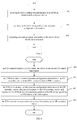
- Fig. 2 is a flowchart of a method for searching for an SS block according to an embodiment of the present disclosure. As shown in Fig. 2 , this method is applied to a user equipment and includes the following steps.
- Step 201 receiving detection configuration information of an SS block transmitted by a network device.
- the above detection configuration information may be configuration information which is used to assist the user equipment to search for the SS block.
- the detection configuration information may be frequency information of a carrier where the SS block is located, location information of the SS block, detection information of a synchronization Signal (SS) sequence in the SS block, or detection information of a Physical Broadcast Channel (PBCH) of the SS block, which is not limited in this embodiment of the present disclosure.
- SS synchronization Signal
- PBCH Physical Broadcast Channel
- Step 202 searching for the SS block according to the detection configuration information.
- the searching for the SS block according to the detection configuration information may include: determining location of the SS block or frequency of the carrier where the SS block is located according to the detection configuration information, and then searching for the SS block at the corresponding location, thereby improving the efficiency of searching for the SS block.
- searching for the SS block may be referred to as SS block blind detection, so that the above steps can reduce the time of the SS block blind detection and save power consumption of the user equipment.
- the network device sends the detection configuration information to the user equipment, so that the user equipment can search for the SS block according to the detection configuration information, thereby improving the efficiency of searching for the SS block by the user equipment.
- the network device may be a primary carrier network device
- the above SS block is an SS block of a secondary carrier and the above detection configuration information includes an SS burst set period
- the user equipment can search for the SS block on the secondary carrier according to the actual SS burst set period.
- This can solve limitation to the frequency at which the secondary carrier network device sends the SS block, caused by that the user equipment searches for the SS block on the secondary carrier according to the default SS burst set period, and support the secondary carrier network device to configure a larger SS burst set period according to needs, so as to save power consumption of the secondary carrier network device.
- the detection configuration information of the SS block sent by the network device is received, and the SS block is searched according to the detection configuration information. Since the user equipment searches for the SS block according to the detection configuration information, the efficiency of searching for the SS block can be improved, thereby reducing time of the SS block blind detection and saving the power consumption of the user equipment.
- Fig. 3 is a flowchart of another method for searching for an SS block according to an embodiment of the present disclosure. As shown in Fig. 3 , this method is applied to a user equipment and includes the following steps.
- Step 301 receiving detection configuration information of an SS block transmitted by a network device.
- Step 302 searching for the SS block according to the detection configuration information.
- the foregoing detection configuration information includes at least one of the following: frequency information of carrier and SS block auxiliary information.
- the carrier is a carrier where the SS block is located, that is, the SS block is transmitted on the carrier.
- the foregoing carrier may also be a secondary carrier.
- the foregoing carrier may also be a primary carrier, which is not limited in this embodiment of the present disclosure.
- the foregoing frequency information may represent a frequency range of the foregoing carrier.
- the foregoing SS block auxiliary information may be related information which is used to assist the user equipment in searching for the SS block in the carrier.
- the searching for the SS block according to the detection configuration information may include:
- the frequency of the carrier may be a frequency range of the carrier.
- the receiving detection configuration information of the SS block transmitted by the network device may include: receiving the detection configuration information of the SS block transmitted by a primary carrier network device.
- the searching for the SS block according to the detection configuration information includes: searching for the SS block on a corresponding secondary carrier according to the detection configuration information.
- the detection configuration information of the SS block of the secondary carrier is obtained through the primary carrier network device, so that the user equipment quickly searches for the SS block of the corresponding secondary carrier.
- the primary carrier network device can send the detection configuration information of the SS block of the secondary carrier to the user equipment, so that the user equipment can quickly search for the SS block of the corresponding secondary carrier.
- the primary carrier network device since the primary carrier network device sends the detection configuration information of the secondary carrier to the user equipment, it can support the secondary carrier network device to configure a larger SS burst set period according to needs, thereby saving the power consumption of the secondary carrier network device.
- the receiving the detection configuration information of the SS block transmitted by the primary carrier network device includes: receiving high layer signaling transmitted by the primary carrier network device, where the high layer signaling includes the detection configuration information of the SS block.
- the detection configuration information can be transmitted through the high layer signaling, so that the signaling overhead can be reduced.
- the foregoing high layer signaling may be Radio Resource Control (RRC) signaling or other high layer signaling, which is not limited in this embodiment of the present disclosure.
- RRC Radio Resource Control
- the detection configuration information may be transmitted through user terminal dedicated signaling.
- the foregoing secondary carrier is an NR carrier, and the primary carrier network device is an LTE network device; or, the secondary carrier is an NR secondary component carrier, and the primary carrier network device is an NR network device.
- the detection configuration information of the secondary carrier is transmitted by the LTE network device in the LTE-NR dual connectivity scenario.
- the detection configuration information of the secondary carrier is transmitted by the NR network device corresponding to the primary carrier.
- the carrier aggregation (CA) or the dual connectivity (DC) mode may be used between the primary carrier and the secondary carrier in the NR multi-carrier scenario.
- the SS block auxiliary information includes at least one of the following:
- Location information of the SS block Location information of the SS block, detection information of an SS sequence, and detection information of PBCH.
- the location of the SS block can be determined according to the SS block auxiliary information
- the SS sequence can be quickly detected according to the detection information of the SS sequence
- a PBCH signal can be quickly detected according to the detection information of the PBCH, thereby further improving the efficiency of searching for the SS block by the user equipment.
- the SS block auxiliary information includes, but not limited to, one or more of the location information of the SS block, the detection information of the SS sequence and the detection information of the PBCH, and may further include other information, which are not limited in the embodiment of the present disclosure.
- the SS sequence may include a Primary Synchronization Signal (PSS) sequence and/or a Secondary Synchronization Signal (SSS) sequence.
- PSS Primary Synchronization Signal
- SSS Secondary Synchronization Signal
- the location information of the SS block includes at least one of the following: time domain location information of the SS block, frequency domain location information of the SS block, and numerology of the carrier where the SS block is located.
- the detection information of the SS sequence includes a cell identifier.
- the detection information of the PBCH includes at least one of the following: power difference between De Modulation Reference Signal (DMRS) of the PBCH and the Secondary Synchronization Signal (SSS), DMRS sequence of the PBCH, and phase offset of the DMRS sequence.
- DMRS De Modulation Reference Signal
- SSS Secondary Synchronization Signal
- the time domain location information of the SS block may be used to indicate time domain location of the SS block.
- the frequency domain location information of the SS block may be used to indicate a frequency location of the SS block in the frequency of the carrier, for example, a frequency location for transmission of the SS burst or frequency location for transmission of the SS block.
- the numerology of the carrier where the SS block is located may be used to indicate parameter configuration of the carrier.
- the cell identifier may be a cell identifier used to generate the SS sequence, for example, a Physical Cell Identifier (PCID).
- the detection information of the SS sequence may also be referred to as related information of the SS sequence.
- the DMRS of the PBCH may be a DMRS for demodulating a PBCH signal, and the PBCH signal can be accurately and quickly detected by the user equipment through the detection information of the PBCH. Further, the detection information of the PBCH may also be referred to as related information of the PBCH.
- the time domain location information of the SS block includes at least one of the following: SS burst set period, location offset of the SS block, location of the SS block in the SS burst set, quantity of SS blocks in the SS burst set, and duration of SS burst in the SS burst set.
- the location offset of the SS block includes a slot offset of the SS block or a subframe offset of the SS block.
- the numerology of the carrier where the SS block is located includes at least one of the following: Subcarrier Spacing (SCS) and Cyclic Prefix (CP) length.
- SCS Subcarrier Spacing
- CP Cyclic Prefix
- the slot offset may indicate that from which slot of one cycle, the transmission of the SS block starts.
- the subframe offset may indicate that from which subframe of one cycle, the transmission of the SS block starts.
- the duration of SS burst may indicate a quantity of symbols occupied by the SS burst.
- the user equipment can accurately and quickly search for the SS block.
- the user equipment can accurately acquire relevant configuration of the carrier, thereby facilitating for searching for the SS block.
- the foregoing method may further include the following steps: Step 303: measuring and reading system information on the carrier where the SS block is located.
- the carrier may be a secondary carrier, and the step 303 may include: after the frequency of the carrier is determined according to the detection configuration information, measuring and reading system information on the carrier.
- the LTE carrier is the primary carrier
- the NR carrier is the secondary carrier
- the user equipment is a Non-Standalone (NSA) terminal.
- NSA Non-Standalone
- Step 401 an NSA terminal searches an LTE carrier, and selects to access an LTE carrier base station.
- Step 402 the LTE base station transmits detection configuration information of an NR secondary carrier to the NSA terminal in form of RRC signaling.
- Step 403 the NSA terminal analyzes the detection configuration information of the NR secondary carrier, determines frequency of the NR secondary carrier, and searches for an SS block in a corresponding position of the NR carrier according to SS block auxiliary information.
- Step 404 the NSA terminal measures and reads system information on the NR secondary carrier.
- both of the primary carrier and the secondary carrier are NR carriers
- the carrier aggregation (CA) or the dual connectivity (DC) mode is used between the primary carrier and the secondary carrier
- the user equipment is a non-independent (NSA) terminal.
- Fig. 5 the following steps are included.
- Step 501 an NSA terminal searches an NR primary component carrier, and selects an NR primary component carrier base station to access;
- Step 502 the NR primary component carrier base station transmits detection configuration information of an NR secondary component carrier to the NSA terminal in form of RRC signaling.
- Step 503 the NSA terminal analyzes the detection configuration information of the NR secondary component carrier, determines frequency of the NR secondary component carrier, and searches for an SS block in a corresponding position of the NR secondary component carrier according to the SS block auxiliary information.
- Step 504 the NSA terminal measures and reads system information on the NR secondary component carrier.
- Fig. 6 is a flowchart of another method for searching for an SS block according to an embodiment of the present disclosure. As shown in Fig. 6 , this method is applied to a network device and includes the following steps.
- Step 601 obtaining detection configuration information of an SS block.
- the foregoing detection configuration information may refer to the corresponding description of the embodiment shown in Fig. 2 and Fig. 3 , which will not be elaborated herein with the same beneficial effects being achieved.
- Step 602 transmitting the detection configuration information to a user equipment, where the detection configuration information is used by the user equipment to search for the SS block according to the detection configuration information.
- the user equipment searching for the SS block may refer to the corresponding description of the embodiment shown in Fig. 2 and Fig. 3 , which will not be elaborated herein with the same beneficial effects being achieved.
- the frequency at which the network device transmits the SS block can be reduced, and then the power consumption of the network device can be saved.
- the foregoing detection configuration information may be generated by the network device, or may be received by the network device from a secondary carrier network device, which is not limited in this embodiment of the present disclosure.
- the detection configuration information includes at least one of the following: frequency information of carrier and SS block auxiliary information.
- the detection configuration information may refer to the corresponding description of the embodiment shown in Fig. 3 , which will not be elaborated herein with the same beneficial effects being achieved.
- the detection configuration information is used by the user equipment to determine frequency of the carrier according to the frequency information and search for the SS block at the frequency; or, the detection configuration information is used by the user equipment to search for frequency of the carrier, and search for the SS block at the frequency according to the SS block auxiliary information; or, the detection configuration information is used by the user equipment to determine frequency of the carrier according to the frequency information and search for the SS block at the frequency according to the SS block auxiliary information.
- the detection configuration information may refer to the corresponding description of the embodiment shown in Fig. 3 , which will not be elaborated herein with the same beneficial effects being achieved.
- the carrier is a secondary carrier
- the network device is a primary carrier network device.
- the detection configuration information is used by the user equipment to search for the SS block on a corresponding secondary carrier according to the detection configuration information.
- the secondary carrier and the primary carrier network device may refer to the corresponding description of the embodiment shown in Fig. 3 , which will not be elaborated herein with the same beneficial effects being achieved.
- transmitting the detection configuration information to the user equipment includes: transmitting high layer signaling to the user equipment, where the high layer signaling includes the detection configuration information of the SS block.
- the transmission of the detection configuration information through the high layer signaling may refer to the corresponding description of the embodiment shown in Fig. 3 , which will not be elaborated herein with the same beneficial effects being achieved.
- the secondary carrier is an NR carrier, and the primary carrier network device is an LTE network device; or, the secondary carrier is an NR secondary component carrier, and the primary carrier network device is an NR network device.
- the secondary carrier may refer to the corresponding description of the embodiment shown in Fig. 3 , which will not be elaborated herein with the same beneficial effects being achieved.
- the SS block auxiliary information includes at least one of the following: Location information of the SS block, detection information of an SS sequence, and detection information of PBCH.
- the SS block auxiliary information may refer to the corresponding description of the embodiment shown in Fig. 3 , which will not be elaborated herein with the same beneficial effects being achieved.
- the location information of the SS block includes at least one of the following: time domain location information of the SS block, frequency domain location information of the SS block, and numerology of the carrier where the SS block is located.
- the detection information of the SS sequence includes a cell identifier.
- the detection information of the PBCH includes at least one of the following: power difference between De Modulation Reference Signal (DMRS) of the PBCH and the Secondary Synchronization Signal (SSS), DMRS sequence of the PBCH, and phase offset of the DMRS sequence.
- DMRS De Modulation Reference Signal
- SSS Secondary Synchronization Signal
- the SS block auxiliary information may refer to the corresponding description of the embodiment shown in Fig. 3 , which will not be elaborated herein with the same beneficial effects being achieved.
- the time domain location information of the SS block includes at least one of the following: SS burst set period, location offset of the SS block, location of the SS block in the SS burst set, quantity of SS blocks in the SS burst set, and duration of SS burst in the SS burst set.
- the location offset of the SS block includes a slot offset of the SS block or a subframe offset of the SS block.
- the numerology of the carrier where the SS block is located includes at least one of the following: Subcarrier Spacing (SCS) and Cyclic Prefix (CP) length.
- SCS Subcarrier Spacing
- CP Cyclic Prefix
- the SS block auxiliary information may refer to the corresponding description of the embodiment shown in Fig. 3 , which will not be elaborated herein with the same beneficial effects being achieved.
- the detection configuration information is transmitted to the user equipment, so that the user equipment can search for the SS block according to the detection configuration information. Since the user equipment searches for the SS block according to the detection configuration information, the efficiency of searching for the SS block can be improved. In addition, the frequency at which the network device transmits the SS block, can be reduced, and then the power consumption of the network device can be saved.
- Fig. 7 is a structural diagram of a user equipment according to an embodiment of the present disclosure. As shown in Fig. 7 , the user equipment 700 includes:
- the detection configuration information includes at least one of the following: frequency information of carrier and SS block auxiliary information.
- the searching module 702 is specifically configured to determine frequency of the carrier according to the frequency information and search for the SS block at the frequency; or, the searching module 702 is specifically configured to search for frequency of the carrier and search for the SS block at the frequency according to the SS block auxiliary information; or, the searching module 702 is specifically configured to determine frequency of the carrier according to the frequency information, and search for the SS block at the frequency according to the SS block auxiliary information.
- the carrier is a secondary carrier
- the receiving module 701 is specifically configured to receive the detection configuration information of the SS block transmitted by a primary carrier network device.
- the searching module 702 is specifically configured to search for the SS block on a corresponding secondary carrier according to the detection configuration information.
- the receiving module 701 is specifically configured to receive high layer signaling transmitted by the primary carrier network device, where the high layer signaling includes the detection configuration information of the SS block.
- the secondary carrier is an NR carrier, and the primary carrier network device is an LTE network device; or, the secondary carrier is an NR secondary component carrier, and the primary carrier network device is an NR network device.
- the SS block auxiliary information includes at least one of the following: Location information of the SS block, detection information of an SS sequence, and detection information of PBCH.
- the location information of the SS block includes at least one of the following: time domain location information of the SS block, frequency domain location information of the SS block, and numerology of the carrier where the SS block is located.
- the detection information of the SS sequence includes a cell identifier.
- the detection information of the PBCH includes at least one of the following: power difference between De Modulation Reference Signal (DMRS) of the PBCH and the Secondary Synchronization Signal (SSS), DMRS sequence of the PBCH, and phase offset of the DMRS sequence.
- DMRS De Modulation Reference Signal
- SSS Secondary Synchronization Signal
- the time domain location information of the SS block includes at least one of the following: SS burst set period, location offset of the SS block, location of the SS block in the SS burst set, quantity of SS blocks in the SS burst set, and duration of SS burst in the SS burst set.
- the location offset of the SS block includes a slot offset of the SS block or a subframe offset of the SS block.
- the numerology of the carrier where the SS block is located includes at least one of the following: Subcarrier Spacing (SCS) and Cyclic Prefix (CP) length.
- SCS Subcarrier Spacing
- CP Cyclic Prefix
- the user equipment 700 further includes: a measuring module 703 configured to measure and read system information on a carrier where the SS block is located.
- the user equipment 700 in this embodiment may be the user equipment in any method embodiment of the present disclosure, and any implementation manner of the user equipment in the method embodiment of the present disclosure may be implemented by the user equipment 700 in this embodiment with the same beneficial effects being achieved, which will not be elaborated herein.
- Fig. 9 is a structural diagram of a network device according to an embodiment of the present disclosure. As shown in Fig. 9 , the network device 900 includes:
- the detection configuration information includes at least one of the following: frequency information of carrier and SS block auxiliary information.
- the detection configuration information is used by the user equipment to determine frequency of the carrier according to the frequency information and search for the SS block at the frequency; or, the detection configuration information is used by the user equipment to search for frequency of the carrier, and search for the SS block at the frequency according to the SS block auxiliary information; or, the detection configuration information is used by the user equipment to determine frequency of the carrier according to the frequency information and search for the SS block at the frequency according to the SS block auxiliary information.
- the carrier is a secondary carrier
- the network device is a primary carrier network device.
- the detection configuration information is used by the user equipment to search for the SS block on a corresponding secondary carrier according to the detection configuration information.
- the transmission module 902 is specifically configured to transmit high layer signaling to the user equipment, where the high layer signaling includes the detection configuration information of the SS block.
- the secondary carrier is an NR carrier, and the primary carrier network device is an LTE network device; or, the secondary carrier is an NR secondary component carrier, and the primary carrier network device is an NR network device.
- the SS block auxiliary information includes at least one of the following: Location information of the SS block, detection information of an SS sequence, and detection information of PBCH.
- the location information of the SS block includes at least one of the following: time domain location information of the SS block, frequency domain location information of the SS block, and numerology of the carrier where the SS block is located.
- the detection information of the SS sequence includes a cell identifier.
- the detection information of the PBCH includes at least one of the following: power difference between De Modulation Reference Signal (DMRS) of the PBCH and the Secondary Synchronization Signal (SSS), DMRS sequence of the PBCH, and phase offset of the DMRS sequence.
- DMRS De Modulation Reference Signal
- SSS Secondary Synchronization Signal
- the time domain location information of the SS block includes at least one of the following: SS burst set period, location offset of the SS block, location of the SS block in the SS burst set, quantity of SS blocks in the SS burst set, and duration of SS burst in the SS burst set.
- the location offset of the SS block includes a slot offset of the SS block or a subframe offset of the SS block.
- the numerology of the carrier where the SS block is located includes at least one of the following: Subcarrier Spacing (SCS) and Cyclic Prefix (CP) length.
- SCS Subcarrier Spacing
- CP Cyclic Prefix
- the network device 900 in this embodiment may be the network device in any method embodiment of the present disclosure, and any implementation manner of the network device in the method embodiment of the present disclosure may be implemented by the network device 900 in this embodiment with the same beneficial effects being achieved, which will not be elaborated herein.
- Fig. 10 is a structural diagram of a user equipment according to another embodiment of the present disclosure.
- the user equipment 1000 includes: at least one processor 1001, a memory 1002, at least one network interface 1004, and a user interface 1003.
- Each component within the user equipment 1000 may be coupled through a bus system 1005.
- the bus system 1005 is configured to implement connection communications among these components.
- the bus system 1005 further includes a power bus, a control bus and a status signal bus.
- various buses in Fig. 10 are labeled as the bus system 1005.
- the user interface 1003 may include a display device, a keyboard, or a clicking device (e.g., a mouse, a track ball, a touch pad, or a touch screen, and so on).
- a clicking device e.g., a mouse, a track ball, a touch pad, or a touch screen, and so on.
- the memory 1002 may be a transitory memory, or a non-transitory memory, or may include both of a transitory memory and a non-transitory memory.
- the non-transitory memory may be a Read-Only Memory (ROM), a Programmable ROM (PROM), an Erasable PROM (EPROM), an Electrically EPROM (EEPROM) or a flash memory.
- the transitory-memory may be a Random Access Memory (RAM), which is taken as an external cache.
- RAM Random Rambus RAM
- SRAM Static RAM
- DRAM Dynamic RAM
- DDRSDRAM Double Data Rate SDRAM
- ESDRAM Enhanced SDRAM
- SLDRAM Synchlink DRAM
- DRRAM Direct Rambus RAM
- the memory 1002 of the system and method described herein is intended to include, without limitation to, these and any other suitable types of memory.
- the memory 1002 includes the following elements, executable modules, or data structures, or their subset, or their extension set: an Operating System (OS) 10021 and an application 10022.
- OS Operating System
- the OS 10021 includes various system programs, such as, a frame layer, a core library layer, a driver layer, and so on, which are configured to implement various basic services and process hardware-based tasks.
- the application 10022 includes various applications, e.g., a Media Player, a Browser, and so on, which are configured to implement various application services.
- the program implementing the method in the embodiment of the present disclosure may be included by the application 10022.
- the processor 1001 by calling the program or instruction stored in the memory 1002, specifically, the program or instruction stored by the application 1002, the processor 1001 is configured to:
- the processor 1001 may be an integrated circuit chip with signal processing capability. In the implementation process, various blocks of foregoing method may be completed, by using the integrated logic circuit of hardware in the processor 1001, or by using instructions in the form of software.
- Foregoing processor 1001 may be a general processor, a Digital Signal Processor (DSP), an Application Specific Integrated Circuit (ASIC), a Field Programmable Gate Array (FPGA), or other programmable logic devices, discrete gates or transistor logic devices, discrete hardware components.
- DSP Digital Signal Processor
- ASIC Application Specific Integrated Circuit
- FPGA Field Programmable Gate Array
- the general processor may be a micro-processor, or any conventional processor, and so on. Combining with method blocks in the embodiments of the present disclosure, it may be directly implemented by a hardware decoding processor, or may be executed by a combination of hardware and software modules in the decoding processor.
- Software modules may be located in a mature storage medium in the field, such as, an RAM, a flash memory, an ROM, a PROM, an electrically erasable programmable memory, a register.
- the storage medium is located in the memory 1002, the processor 1001 reads information in the memory 1002, and completes foregoing method blocks in combination with the hardware.
- a processing unit may be implemented in one or more ASICs, DSPs, DSP Devices (DSPDs), Programmable Logic Device (PLDs), FPGAs, general processors, controllers, micro-controllers, micro-processors, other electronic units or combinations thereof for performing the functions described in the application.
- ASICs ASICs
- DSPs DSP Devices
- PLDs Programmable Logic Device
- FPGAs FPGAs
- general processors controllers, micro-controllers, micro-processors, other electronic units or combinations thereof for performing the functions described in the application.
- the techniques described in the application may be implemented by modules (e.g., procedures, functions, etc.) that perform the functions of the application.
- Software codes may be stored in the memory, and executed by the processor.
- the memory may be implemented in the processor or external to the processor.
- the detection configuration information includes at least one of the following: frequency information of carrier and SS block auxiliary information.
- searching for the SS block according to the detection configuration information, that is performed by the processor 1001 includes:
- the carrier is a secondary carrier.
- the receiving detection configuration information of the SS block transmitted by the network device, that is performed by the processor 1001 includes: receiving the detection configuration information of the SS block transmitted by a primary carrier network device.
- the searching for the SS block according to the detection configuration information includes: searching for the SS block on a corresponding secondary carrier according to the detection configuration information.
- the receiving the detection configuration information of the SS block transmitted by the primary carrier network device includes: receiving high layer signaling transmitted by the primary carrier network device, where the high layer signaling includes the detection configuration information of the SS block.
- the secondary carrier is an NR carrier, and the primary carrier network device is an LTE network device; or, the secondary carrier is an NR secondary component carrier, and the primary carrier network device is an NR network device.
- the SS block auxiliary information includes at least one of the following: Location information of the SS block, detection information of an SS sequence, and detection information of PBCH.
- the location information of the SS block includes at least one of the following: time domain location information of the SS block, frequency domain location information of the SS block, and numerology of the carrier where the SS block is located.
- the detection information of the SS sequence includes a cell identifier.
- the detection information of the PBCH includes at least one of the following: power difference between De Modulation Reference Signal (DMRS) of the PBCH and the Secondary Synchronization Signal (SSS), DMRS sequence of the PBCH, and phase offset of the DMRS sequence.
- DMRS De Modulation Reference Signal
- SSS Secondary Synchronization Signal
- the time domain location information of the SS block includes at least one of the following: SS burst set period, location offset of the SS block, location of the SS block in the SS burst set, quantity of SS blocks in the SS burst set, and duration of SS burst in the SS burst set.
- the location offset of the SS block includes a slot offset of the SS block or a subframe offset of the SS block.
- the numerology of the carrier where the SS block is located includes at least one of the following: Subcarrier Spacing (SCS) and Cyclic Prefix (CP) length.
- SCS Subcarrier Spacing
- CP Cyclic Prefix
- the processor 1001 is further configured to: measure and read system information on the carrier where the SS block is located.
- the user equipment 1000 in this embodiment may be the user equipment in any method embodiment of the present disclosure, and any implementation manner of the user equipment in the method embodiment of the present disclosure may be implemented by the user equipment 1000 in this embodiment with the same beneficial effects being achieved, which will not be elaborated herein.
- Fig. 11 is a structural diagram of a network device according to another embodiment of the present disclosure.
- the network device 1100 includes: a processor 1101, a transceiver 1102, a memory 1103, a user interface 1104, and a bus interface.
- the processor 1101 is configured to read a program in the memory 1103 and perform the following process:
- the transceiver 1102 is configured to receive and transmit data under the control of the processor 1101, and the transceiver 1102 includes at least two antenna ports.
- the bus architecture may include any number of interconnected buses and bridges. Specifically, one or more processors represented by the processor 1001 and various circuits of memory represented by the memory 1003 are linked together. The bus architecture can also link various other circuits, such as peripherals, voltage regulators, and power management circuits, as is known in the art. Therefore, it will not be further described.
- the bus interface provides an interface.
- the transceiver 1002 may be multiple components, including a transmitter and a receiver, providing units for communicating with various other devices on a transmission medium.
- the user interface 1104 may also be an interface capable of externally connecting required devices, including but not limited to a keypad, a display device, a speaker, a microphone, a joystick, and the like.
- the processor 1101 is responsible for managing the bus architecture and general processing, and the memory 1103 can store data used by the processor 1101 when performing operations.
- the detection configuration information includes at least one of the following: frequency information of carrier and SS block auxiliary information.
- the detection configuration information is used by the user equipment to determine frequency of the carrier according to the frequency information and search for the SS block at the frequency; or, the detection configuration information is used by the user equipment to search for frequency of the carrier, and search for the SS block at the frequency according to the SS block auxiliary information; or, the detection configuration information is used by the user equipment to determine frequency of the carrier according to the frequency information and search for the SS block at the frequency according to the SS block auxiliary information.
- the carrier is a secondary carrier
- the network device is a primary carrier network device.
- the detection configuration information is used by the user equipment to search for the SS block on a corresponding secondary carrier according to the detection configuration information.
- transmitting the detection configuration information to the user equipment includes: transmitting high layer signaling to the user equipment, where the high layer signaling includes the detection configuration information of the SS block.
- the secondary carrier is an NR carrier, and the primary carrier network device is an LTE network device; or, the secondary carrier is an NR secondary component carrier, and the primary carrier network device is an NR network device.
- the SS block auxiliary information includes at least one of the following: Location information of the SS block, detection information of an SS sequence, and detection information of PBCH.
- the location information of the SS block includes at least one of the following: time domain location information of the SS block, frequency domain location information of the SS block, and numerology of the carrier where the SS block is located.
- the detection information of the SS sequence includes a cell identifier.
- the detection information of the PBCH includes at least one of the following: power difference between De Modulation Reference Signal (DMRS) of the PBCH and the Secondary Synchronization Signal (SSS), DMRS sequence of the PBCH, and phase offset of the DMRS sequence.
- DMRS De Modulation Reference Signal
- SSS Secondary Synchronization Signal
- the time domain location information of the SS block includes at least one of the following: SS burst set period, location offset of the SS block, location of the SS block in the SS burst set, quantity of SS blocks in the SS burst set, and duration of SS burst in the SS burst set.
- the location offset of the SS block includes a slot offset of the SS block or a subframe offset of the SS block.
- the numerology of the carrier where the SS block is located includes at least one of the following: Subcarrier Spacing (SCS) and Cyclic Prefix (CP) length.
- SCS Subcarrier Spacing
- CP Cyclic Prefix
- the network device 1100 in this embodiment may be the network device in any method embodiment of the present disclosure, and any implementation manner of the network device in the method embodiment of the present disclosure may be implemented by the network device 1100 in this embodiment with the same beneficial effects being achieved, which will not be elaborated herein.
- One embodiment of the present disclosure further provides a computer readable storage medium, which stores a search program of the SS block.
- the search program of the SS block is executed by the processor to implement steps of the method for searching for SS block on the user equipment according to the embodiment of the present disclosure.
- One embodiment of the present disclosure further provides a computer readable storage medium, which stores a search program of the SS block.
- the search program of the SS block is executed by the processor to implement steps of the method for searching for SS block on the network device according to the embodiment of the present disclosure.
- the disclosed devices and methods may be implemented with other methods.
- the above-described device embodiments are only illustrative, e.g., the division of the unit is only a logic function division. In practical implementation, there may be another division method. For example, multiple units or components may be combined, or integrated into another system, or some features may be omitted, or not executed. From another point, the mutual coupling or direct coupling, or communication connection shown or discussed may be indirect coupling, or communication connections through some interfaces, devices, or units, which may be electronic, mechanical, or in other form.
- Units described as separate components may be, or may be not physically separate.
- a component displayed as a unit may be, or may be not a physical unit, that is, it may be located in one place, or may be distributed to multiple network units. According to practical requirements, some units or all the units may be selected to implement the objective of solutions in the embodiments of the application.
- each unit physically exists alone.
- two or more units may be integrated into one unit.
- Such software functional unit When the functions are implemented in the form of software functional unit, which is sold or used as an independent product, such software functional unit may be stored in a computer readable storage medium.
- the computer software produce is stored in one storage medium, including several instructions to enable a computer device (may be a Personal Computer (PC), a server, or a network device, etc.) to implement all the blocks, or some blocks in the method of each embodiment of the present disclosure.
- a computer device may be a Personal Computer (PC), a server, or a network device, etc.
- Foregoing storage medium includes various media that can store program codes, such as a U disk, a mobile hard disk, an ROM, an RAM, a disk, or a Compact Disk (CD), and so on.
Landscapes
- Engineering & Computer Science (AREA)
- Signal Processing (AREA)
- Computer Networks & Wireless Communication (AREA)
- Computer Security & Cryptography (AREA)
- Databases & Information Systems (AREA)
- Mobile Radio Communication Systems (AREA)
Abstract
Description
- This application claims the benefit and priority of Chinese Application No.
201710474320.4, filed on June 21, 2017 - The present disclosure relates to the field of communication technologies, and in particular to a method, a related device and a system for searching for a Synchronization Signal Block (SS block).
- In a communication system (for example, the 5G system), in order to realize a user equipment's initial access and radio resource management (RRM) measurement, a network device is required to transmit a synchronization signal block (SS block), which may also be referred to as physical channel block, for the user equipment to perform measurement evaluation. A plurality of SS blocks form a Synchronization Signal burst (SS burst), and a plurality of SS bursts form a Synchronization Signal burst set (SS burst set).
- Currently, the user equipment searches for the SS block according to the default SS burst set period (20 milliseconds). Due to the large span of frequency bands of New Radio (NR), the user equipment may have to perform a full-band search to determine a working carrier of a cell and then continue to perform the SS block search on the carrier. It can be seen that the efficiency of searching for the SS block by the user equipment in the related art is relatively low.
- According to a first aspect, one embodiment of the present disclosure provides a method for searching for a synchronization signal block (SS block), which is applied to user equipment, including:
- receiving detection configuration information of the SS block transmitted by a network device; and
- searching for the SS block according to the detection configuration information.
- According to a second aspect, one embodiment of the present disclosure provides a method for searching for a synchronization signal block (SS block), which is applied to a network device, including:
- obtaining detection configuration information of the SS block; and
- transmitting the detection configuration information to user equipment, wherein the detection configuration information is used by the user equipment to search for the SS block according to the detection configuration information.
- According to a third aspect, one embodiment of the present disclosure provides user equipment including:
- a receiving module configured to receive detection configuration information of a Synchronization Signal Block (SS block) transmitted by a network device; and
- a searching module configured to search for the SS block according to the detection configuration information.
- According to a fourth aspect, one embodiment of the present disclosure provides a network device, including:
- an obtaining module configured to obtain detection configuration information of a Synchronization Signal Block (SS block); and
- a transmission module configured to transmit the detection configuration information to user equipment, wherein the detection configuration information is used by the user equipment to search for the SS block according to the detection configuration information.
- According to a fifth aspect, one embodiment of the present disclosure provides a user equipment, including: a processor, a memory, a network interface and a user interface. The processor, the memory, the network interface and the user interface are coupled together by a bus system, the processor is configured to read a program in the memory to perform steps in the method for searching for a synchronization signal block (SS block), which is applied to the user equipment.
- According to a sixth aspect, one embodiment of the present disclosure provides a network device including: a processor, a memory, a transceiver and a user interface. The processor, the memory, the transceiver and the user interface are coupled together by a bus system, and the processor is configured to read a program in the memory to perform steps in the method for searching for a synchronization signal block (SS block), which is applied to the network device.
- According to a seventh aspect, one embodiment of the present disclosure provides a system for searching for a Synchronization Signal Block (SS block), including the user equipment and the network device.
- According to an eighth aspect, one embodiment of the present disclosure provides a computer readable storage medium including a search program of a Synchronization Signal Block (SS block) stored therein. The search program of the SS block is executed by a processor to implement steps of the method for searching for a synchronization signal block (SS block), which is applied to the user equipment.
- According to a ninth aspect, one embodiment of the present disclosure provides a computer readable storage medium including a search program of a Synchronization Signal Block (SS block) stored therein. The search program of the SS block is executed by a processor to implement steps of the method for searching for a synchronization signal block (SS block), which is applied to the network device.
- In order to illustrate technical solutions according to embodiments of the present disclosure more clearly, drawings to be used in the description of the embodiments will be described briefly hereinafter. Apparently, the drawings described hereinafter are only some embodiments of the present disclosure, and other drawings may be obtained by those skilled in the art according to those drawings without creative work.
-
Fig. 1 is a structural diagram of a system for searching for an SS block according to an embodiment of the present disclosure; -
Fig. 2 is a flowchart of a method for searching for an SS block according to an embodiment of the present disclosure; -
Fig. 3 is a flowchart of another method for searching for an SS block according to an embodiment of the present disclosure; -
Fig. 4 is a flowchart of another method for searching for an SS block according to an embodiment of the present disclosure; -
Fig. 5 is a flowchart of another method for searching for an SS block according to an embodiment of the present disclosure; -
Fig. 6 is a flowchart of another method for searching for an SS block according to an embodiment of the present disclosure; -
Fig. 7 is a structural diagram of a user equipment according to an embodiment of the present disclosure; -
Fig. 8 is a structural diagram of a user equipment according to another embodiment of the present disclosure; -
Fig. 9 is a structural diagram of a network device according to an embodiment of the present disclosure; -
Fig. 10 is a structural diagram of a user equipment according to another embodiment of the present disclosure; and -
Fig. 11 is a structural diagram of a network device according to another embodiment of the present disclosure. - The technical solutions in the embodiments of the present disclosure are clearly and completely described in the following with reference to the accompanying drawings in the embodiments of the present disclosure. It is obvious that the described embodiments are a part of the embodiments of the present disclosure, and not all of the embodiments. All other embodiments obtained by a person of ordinary skill in the art based on the embodiments of the present disclosure without departing from the inventive scope are the scope of the disclosure.
- Referring to
Fig. 1, Fig. 1 is a structural diagram of a system for searching for an SS block according to an embodiment of the present disclosure. As shown inFig. 1 , the system includes a user equipment (UE) 11 and anetwork device 12. Theuser equipment 11 may be a terminal device, e.g., a mobile phone, a Tablet Personal Computer, a Laptop Computer, a personal digital assistant (PDA), a Mobile Internet Device (MID), or a Wearable Device. It should be noted that, in the embodiments of the present disclosure, specific type of theuser equipment 11 is not limited. Theuser equipment 11 can establish communication with thenetwork device 12. In the network shown in the attached figure, theuser equipment 11 can establish wireless communication with thenetwork device 12. Thenetwork device 12 may be a Transmission Reception Point (TRP) or a base station. The base station may be a macro station, such as, LTE eNB, 5G NR NB. Thenetwork device 12 may also be an Access Point (AP). - It should be noted that, in the embodiments of the present disclosure, specific type of the
network device 12 is not limited. The specific functions of theuser equipment 11 and thenetwork device 12 will be described in details with the following embodiments. - Referring to
Fig. 2, Fig. 2 is a flowchart of a method for searching for an SS block according to an embodiment of the present disclosure. As shown inFig. 2 , this method is applied to a user equipment and includes the following steps. - Step 201: receiving detection configuration information of an SS block transmitted by a network device.
- The above detection configuration information may be configuration information which is used to assist the user equipment to search for the SS block. For example, the detection configuration information may be frequency information of a carrier where the SS block is located, location information of the SS block, detection information of a synchronization Signal (SS) sequence in the SS block, or detection information of a Physical Broadcast Channel (PBCH) of the SS block, which is not limited in this embodiment of the present disclosure.
- Step 202: searching for the SS block according to the detection configuration information.
- The searching for the SS block according to the detection configuration information may include: determining location of the SS block or frequency of the carrier where the SS block is located according to the detection configuration information, and then searching for the SS block at the corresponding location, thereby improving the efficiency of searching for the SS block. In addition, searching for the SS block may be referred to as SS block blind detection, so that the above steps can reduce the time of the SS block blind detection and save power consumption of the user equipment. In addition, the network device sends the detection configuration information to the user equipment, so that the user equipment can search for the SS block according to the detection configuration information, thereby improving the efficiency of searching for the SS block by the user equipment. For example, the network device may be a primary carrier network device, the above SS block is an SS block of a secondary carrier and the above detection configuration information includes an SS burst set period, then the user equipment can search for the SS block on the secondary carrier according to the actual SS burst set period. This can solve limitation to the frequency at which the secondary carrier network device sends the SS block, caused by that the user equipment searches for the SS block on the secondary carrier according to the default SS burst set period, and support the secondary carrier network device to configure a larger SS burst set period according to needs, so as to save power consumption of the secondary carrier network device.
- It should be noted that the foregoing method may be applied to the 5G or LTE evolved communication system.
- In this embodiment, the detection configuration information of the SS block sent by the network device is received, and the SS block is searched according to the detection configuration information. Since the user equipment searches for the SS block according to the detection configuration information, the efficiency of searching for the SS block can be improved, thereby reducing time of the SS block blind detection and saving the power consumption of the user equipment.
- Referring to
Fig. 3, Fig. 3 is a flowchart of another method for searching for an SS block according to an embodiment of the present disclosure. As shown inFig. 3 , this method is applied to a user equipment and includes the following steps. - Step 301: receiving detection configuration information of an SS block transmitted by a network device.
- Step 302: searching for the SS block according to the detection configuration information.
- Optionally, the foregoing detection configuration information includes at least one of the following:
frequency information of carrier and SS block auxiliary information. - The carrier is a carrier where the SS block is located, that is, the SS block is transmitted on the carrier. In addition, in the scenario where the user equipment is in dual connectivity, such as Long Term Evolution (LTE) and NR dual connection, or in NR multi-carrier scenario, the foregoing carrier may also be a secondary carrier. Of course, in some scenarios, the foregoing carrier may also be a primary carrier, which is not limited in this embodiment of the present disclosure.
- In addition, the foregoing frequency information may represent a frequency range of the foregoing carrier. The foregoing SS block auxiliary information may be related information which is used to assist the user equipment in searching for the SS block in the carrier.
- In this embodiment, the searching for the SS block according to the detection configuration information, may include:
- determining frequency of the carrier according to the frequency information, and searching for the SS block at the frequency; or,
- searching for frequency of the carrier, and searching for the SS block at the frequency according to the SS block auxiliary information; or,
- determining frequency of the carrier according to the frequency information, and searching for the SS block at the frequency according to the SS block auxiliary information.
- The frequency of the carrier may be a frequency range of the carrier. Through the foregoing steps, the user equipment can quickly search for the SS block.
- In addition, if the carrier is the secondary carrier, the receiving detection configuration information of the SS block transmitted by the network device, may include:
receiving the detection configuration information of the SS block transmitted by a primary carrier network device. - The searching for the SS block according to the detection configuration information, includes:
searching for the SS block on a corresponding secondary carrier according to the detection configuration information. - In this implementation manner, the detection configuration information of the SS block of the secondary carrier is obtained through the primary carrier network device, so that the user equipment quickly searches for the SS block of the corresponding secondary carrier. For example, after the user equipment accesses the primary carrier network device, the primary carrier network device can send the detection configuration information of the SS block of the secondary carrier to the user equipment, so that the user equipment can quickly search for the SS block of the corresponding secondary carrier. In this embodiment, since the primary carrier network device sends the detection configuration information of the secondary carrier to the user equipment, it can support the secondary carrier network device to configure a larger SS burst set period according to needs, thereby saving the power consumption of the secondary carrier network device.
- Optionally, the receiving the detection configuration information of the SS block transmitted by the primary carrier network device, includes:
receiving high layer signaling transmitted by the primary carrier network device, where the high layer signaling includes the detection configuration information of the SS block. - In this implementation manner, the detection configuration information can be transmitted through the high layer signaling, so that the signaling overhead can be reduced. The foregoing high layer signaling may be Radio Resource Control (RRC) signaling or other high layer signaling, which is not limited in this embodiment of the present disclosure. Besides, the detection configuration information may be transmitted through user terminal dedicated signaling.
- Optionally, the foregoing secondary carrier is an NR carrier, and the primary carrier network device is an LTE network device; or,
the secondary carrier is an NR secondary component carrier, and the primary carrier network device is an NR network device. - In this embodiment, the detection configuration information of the secondary carrier is transmitted by the LTE network device in the LTE-NR dual connectivity scenario. Besides, in the NR multi-carrier scenario, the detection configuration information of the secondary carrier is transmitted by the NR network device corresponding to the primary carrier. The carrier aggregation (CA) or the dual connectivity (DC) mode may be used between the primary carrier and the secondary carrier in the NR multi-carrier scenario.
- Optionally, the SS block auxiliary information includes at least one of the following:
- Location information of the SS block, detection information of an SS sequence, and detection information of PBCH.
- In this implementation manner, the location of the SS block can be determined according to the SS block auxiliary information, the SS sequence can be quickly detected according to the detection information of the SS sequence, and a PBCH signal can be quickly detected according to the detection information of the PBCH, thereby further improving the efficiency of searching for the SS block by the user equipment. In addition, in the embodiment of the present disclosure, the SS block auxiliary information includes, but not limited to, one or more of the location information of the SS block, the detection information of the SS sequence and the detection information of the PBCH, and may further include other information, which are not limited in the embodiment of the present disclosure. In addition, the SS sequence may include a Primary Synchronization Signal (PSS) sequence and/or a Secondary Synchronization Signal (SSS) sequence.
- Optionally, the location information of the SS block includes at least one of the following:
time domain location information of the SS block, frequency domain location information of the SS block, and numerology of the carrier where the SS block is located. - The detection information of the SS sequence includes a cell identifier.
- The detection information of the PBCH includes at least one of the following:
power difference between De Modulation Reference Signal (DMRS) of the PBCH and the Secondary Synchronization Signal (SSS), DMRS sequence of the PBCH, and phase offset of the DMRS sequence. - The time domain location information of the SS block may be used to indicate time domain location of the SS block. The frequency domain location information of the SS block may be used to indicate a frequency location of the SS block in the frequency of the carrier, for example, a frequency location for transmission of the SS burst or frequency location for transmission of the SS block. The numerology of the carrier where the SS block is located, may be used to indicate parameter configuration of the carrier.
- In addition, the cell identifier may be a cell identifier used to generate the SS sequence, for example, a Physical Cell Identifier (PCID). The detection information of the SS sequence may also be referred to as related information of the SS sequence. The DMRS of the PBCH may be a DMRS for demodulating a PBCH signal, and the PBCH signal can be accurately and quickly detected by the user equipment through the detection information of the PBCH. Further, the detection information of the PBCH may also be referred to as related information of the PBCH.
- Optionally, the time domain location information of the SS block includes at least one of the following:
SS burst set period, location offset of the SS block, location of the SS block in the SS burst set, quantity of SS blocks in the SS burst set, and duration of SS burst in the SS burst set. - The location offset of the SS block includes a slot offset of the SS block or a subframe offset of the SS block.
- The numerology of the carrier where the SS block is located includes at least one of the following:
Subcarrier Spacing (SCS) and Cyclic Prefix (CP) length. - The slot offset may indicate that from which slot of one cycle, the transmission of the SS block starts. The subframe offset may indicate that from which subframe of one cycle, the transmission of the SS block starts. The duration of SS burst may indicate a quantity of symbols occupied by the SS burst.
- Through the time domain location information of the SS block, the user equipment can accurately and quickly search for the SS block.
- In addition, through the above numerology, the user equipment can accurately acquire relevant configuration of the carrier, thereby facilitating for searching for the SS block.
- Optionally, the foregoing method may further include the following steps:
Step 303: measuring and reading system information on the carrier where the SS block is located. - The carrier may be a secondary carrier, and the
step 303 may include: after the frequency of the carrier is determined according to the detection configuration information, measuring and reading system information on the carrier. - Description will be described hereinafter with an example of the LTE-NR dual connectivity scenario, in which the LTE carrier is the primary carrier, the NR carrier is the secondary carrier, and the user equipment is a Non-Standalone (NSA) terminal. As shown in
Fig. 4 , the following steps are included. - Step 401: an NSA terminal searches an LTE carrier, and selects to access an LTE carrier base station.
- Step 402: the LTE base station transmits detection configuration information of an NR secondary carrier to the NSA terminal in form of RRC signaling.
- Step 403: the NSA terminal analyzes the detection configuration information of the NR secondary carrier, determines frequency of the NR secondary carrier, and searches for an SS block in a corresponding position of the NR carrier according to SS block auxiliary information.
- Step 404: the NSA terminal measures and reads system information on the NR secondary carrier.
- Description will be described hereinafter with an example of an NR multi-carrier network, in which both of the primary carrier and the secondary carrier are NR carriers, the carrier aggregation (CA) or the dual connectivity (DC) mode is used between the primary carrier and the secondary carrier, and the user equipment is a non-independent (NSA) terminal. As shown in
Fig. 5 , the following steps are included. - Step 501: an NSA terminal searches an NR primary component carrier, and selects an NR primary component carrier base station to access;
- Step 502: the NR primary component carrier base station transmits detection configuration information of an NR secondary component carrier to the NSA terminal in form of RRC signaling.
- Step 503: the NSA terminal analyzes the detection configuration information of the NR secondary component carrier, determines frequency of the NR secondary component carrier, and searches for an SS block in a corresponding position of the NR secondary component carrier according to the SS block auxiliary information.
- Step 504: the NSA terminal measures and reads system information on the NR secondary component carrier.
- Referring to
Fig. 6, Fig. 6 is a flowchart of another method for searching for an SS block according to an embodiment of the present disclosure. As shown inFig. 6 , this method is applied to a network device and includes the following steps. - Step 601: obtaining detection configuration information of an SS block.
- The foregoing detection configuration information may refer to the corresponding description of the embodiment shown in
Fig. 2 andFig. 3 , which will not be elaborated herein with the same beneficial effects being achieved. - Step 602: transmitting the detection configuration information to a user equipment, where the detection configuration information is used by the user equipment to search for the SS block according to the detection configuration information.
- The user equipment searching for the SS block may refer to the corresponding description of the embodiment shown in
Fig. 2 andFig. 3 , which will not be elaborated herein with the same beneficial effects being achieved. In addition, the frequency at which the network device transmits the SS block, can be reduced, and then the power consumption of the network device can be saved. - In addition, in the embodiment of the present disclosure, the foregoing detection configuration information may be generated by the network device, or may be received by the network device from a secondary carrier network device, which is not limited in this embodiment of the present disclosure.
- Optionally, the detection configuration information includes at least one of the following:
frequency information of carrier and SS block auxiliary information. - The detection configuration information may refer to the corresponding description of the embodiment shown in
Fig. 3 , which will not be elaborated herein with the same beneficial effects being achieved. - Optionally, the detection configuration information is used by the user equipment to determine frequency of the carrier according to the frequency information and search for the SS block at the frequency; or,
the detection configuration information is used by the user equipment to search for frequency of the carrier, and search for the SS block at the frequency according to the SS block auxiliary information; or,
the detection configuration information is used by the user equipment to determine frequency of the carrier according to the frequency information and search for the SS block at the frequency according to the SS block auxiliary information. - The detection configuration information may refer to the corresponding description of the embodiment shown in
Fig. 3 , which will not be elaborated herein with the same beneficial effects being achieved. - Optionally, the carrier is a secondary carrier, and the network device is a primary carrier network device.
- The detection configuration information is used by the user equipment to search for the SS block on a corresponding secondary carrier according to the detection configuration information.
- The secondary carrier and the primary carrier network device may refer to the corresponding description of the embodiment shown in
Fig. 3 , which will not be elaborated herein with the same beneficial effects being achieved. - Optionally, transmitting the detection configuration information to the user equipment, includes:
transmitting high layer signaling to the user equipment, where the high layer signaling includes the detection configuration information of the SS block. - The transmission of the detection configuration information through the high layer signaling may refer to the corresponding description of the embodiment shown in
Fig. 3 , which will not be elaborated herein with the same beneficial effects being achieved. - Optionally, the secondary carrier is an NR carrier, and the primary carrier network device is an LTE network device; or,
the secondary carrier is an NR secondary component carrier, and the primary carrier network device is an NR network device. - The secondary carrier may refer to the corresponding description of the embodiment shown in
Fig. 3 , which will not be elaborated herein with the same beneficial effects being achieved. - Optionally, the SS block auxiliary information includes at least one of the following:
Location information of the SS block, detection information of an SS sequence, and detection information of PBCH. - The SS block auxiliary information may refer to the corresponding description of the embodiment shown in
Fig. 3 , which will not be elaborated herein with the same beneficial effects being achieved. - Optionally, the location information of the SS block includes at least one of the following:
time domain location information of the SS block, frequency domain location information of the SS block, and numerology of the carrier where the SS block is located. - The detection information of the SS sequence includes a cell identifier.
- The detection information of the PBCH includes at least one of the following:
power difference between De Modulation Reference Signal (DMRS) of the PBCH and the Secondary Synchronization Signal (SSS), DMRS sequence of the PBCH, and phase offset of the DMRS sequence. - The SS block auxiliary information may refer to the corresponding description of the embodiment shown in
Fig. 3 , which will not be elaborated herein with the same beneficial effects being achieved. - Optionally, the time domain location information of the SS block includes at least one of the following:
SS burst set period, location offset of the SS block, location of the SS block in the SS burst set, quantity of SS blocks in the SS burst set, and duration of SS burst in the SS burst set. - The location offset of the SS block includes a slot offset of the SS block or a subframe offset of the SS block.
- The numerology of the carrier where the SS block is located includes at least one of the following:
Subcarrier Spacing (SCS) and Cyclic Prefix (CP) length. - The SS block auxiliary information may refer to the corresponding description of the embodiment shown in
Fig. 3 , which will not be elaborated herein with the same beneficial effects being achieved. - In this embodiment, the detection configuration information is transmitted to the user equipment, so that the user equipment can search for the SS block according to the detection configuration information. Since the user equipment searches for the SS block according to the detection configuration information, the efficiency of searching for the SS block can be improved. In addition, the frequency at which the network device transmits the SS block, can be reduced, and then the power consumption of the network device can be saved.
- Referring to
Fig. 7, Fig. 7 is a structural diagram of a user equipment according to an embodiment of the present disclosure. As shown inFig. 7 , theuser equipment 700 includes: - a
receiving module 701 configured to receive detection configuration information of an SS block transmitted by a network device; - a searching
module 702 configured to search for the SS block according to the detection configuration information. - Optionally, the detection configuration information includes at least one of the following:
frequency information of carrier and SS block auxiliary information. - Optionally, the searching
module 702 is specifically configured to determine frequency of the carrier according to the frequency information and search for the SS block at the frequency; or,
the searchingmodule 702 is specifically configured to search for frequency of the carrier and search for the SS block at the frequency according to the SS block auxiliary information; or,
the searchingmodule 702 is specifically configured to determine frequency of the carrier according to the frequency information, and search for the SS block at the frequency according to the SS block auxiliary information. - Optionally, the carrier is a secondary carrier, and the receiving
module 701 is specifically configured to receive the detection configuration information of the SS block transmitted by a primary carrier network device. - The searching
module 702 is specifically configured to search for the SS block on a corresponding secondary carrier according to the detection configuration information. - Optionally, the receiving
module 701 is specifically configured to receive high layer signaling transmitted by the primary carrier network device, where the high layer signaling includes the detection configuration information of the SS block. - Optionally, the secondary carrier is an NR carrier, and the primary carrier network device is an LTE network device; or,
the secondary carrier is an NR secondary component carrier, and the primary carrier network device is an NR network device. - Optionally, the SS block auxiliary information includes at least one of the following:
Location information of the SS block, detection information of an SS sequence, and detection information of PBCH. - Optionally, the location information of the SS block includes at least one of the following:
time domain location information of the SS block, frequency domain location information of the SS block, and numerology of the carrier where the SS block is located. - The detection information of the SS sequence includes a cell identifier.
- The detection information of the PBCH includes at least one of the following:
power difference between De Modulation Reference Signal (DMRS) of the PBCH and the Secondary Synchronization Signal (SSS), DMRS sequence of the PBCH, and phase offset of the DMRS sequence. - Optionally, the time domain location information of the SS block includes at least one of the following:
SS burst set period, location offset of the SS block, location of the SS block in the SS burst set, quantity of SS blocks in the SS burst set, and duration of SS burst in the SS burst set. - The location offset of the SS block includes a slot offset of the SS block or a subframe offset of the SS block.
- The numerology of the carrier where the SS block is located includes at least one of the following:
Subcarrier Spacing (SCS) and Cyclic Prefix (CP) length. - Optionally, as shown in
Fig. 8 , theuser equipment 700 further includes:
ameasuring module 703 configured to measure and read system information on a carrier where the SS block is located. - It should be noted that, the
user equipment 700 in this embodiment may be the user equipment in any method embodiment of the present disclosure, and any implementation manner of the user equipment in the method embodiment of the present disclosure may be implemented by theuser equipment 700 in this embodiment with the same beneficial effects being achieved, which will not be elaborated herein. - Referring to
Fig. 9, Fig. 9 is a structural diagram of a network device according to an embodiment of the present disclosure. As shown inFig. 9 , thenetwork device 900 includes: - an obtaining
module 901 configured to obtain detection configuration information of an SS block; - a
transmission module 902 configured to transmit the detection configuration information to a user equipment, where the detection configuration information is used by the user equipment to search for the SS block according to the detection configuration information. - Optionally, the detection configuration information includes at least one of the following:
frequency information of carrier and SS block auxiliary information. - Optionally, the detection configuration information is used by the user equipment to determine frequency of the carrier according to the frequency information and search for the SS block at the frequency; or,
the detection configuration information is used by the user equipment to search for frequency of the carrier, and search for the SS block at the frequency according to the SS block auxiliary information; or,
the detection configuration information is used by the user equipment to determine frequency of the carrier according to the frequency information and search for the SS block at the frequency according to the SS block auxiliary information. - Optionally, the carrier is a secondary carrier, and the network device is a primary carrier network device.
- The detection configuration information is used by the user equipment to search for the SS block on a corresponding secondary carrier according to the detection configuration information.
- Optionally, the
transmission module 902 is specifically configured to transmit high layer signaling to the user equipment, where the high layer signaling includes the detection configuration information of the SS block. - Optionally, the secondary carrier is an NR carrier, and the primary carrier network device is an LTE network device; or,
the secondary carrier is an NR secondary component carrier, and the primary carrier network device is an NR network device. - Optionally, the SS block auxiliary information includes at least one of the following:
Location information of the SS block, detection information of an SS sequence, and detection information of PBCH. - Optionally, the location information of the SS block includes at least one of the following:
time domain location information of the SS block, frequency domain location information of the SS block, and numerology of the carrier where the SS block is located. - The detection information of the SS sequence includes a cell identifier.
- The detection information of the PBCH includes at least one of the following:
power difference between De Modulation Reference Signal (DMRS) of the PBCH and the Secondary Synchronization Signal (SSS), DMRS sequence of the PBCH, and phase offset of the DMRS sequence. - Optionally, the time domain location information of the SS block includes at least one of the following:
SS burst set period, location offset of the SS block, location of the SS block in the SS burst set, quantity of SS blocks in the SS burst set, and duration of SS burst in the SS burst set. - The location offset of the SS block includes a slot offset of the SS block or a subframe offset of the SS block.
- The numerology of the carrier where the SS block is located includes at least one of the following:
Subcarrier Spacing (SCS) and Cyclic Prefix (CP) length. - It should be noted that, the
network device 900 in this embodiment may be the network device in any method embodiment of the present disclosure, and any implementation manner of the network device in the method embodiment of the present disclosure may be implemented by thenetwork device 900 in this embodiment with the same beneficial effects being achieved, which will not be elaborated herein. - Referring to
Fig. 10, Fig. 10 is a structural diagram of a user equipment according to another embodiment of the present disclosure. As shown inFig 10 , theuser equipment 1000 includes: at least oneprocessor 1001, amemory 1002, at least onenetwork interface 1004, and auser interface 1003. Each component within theuser equipment 1000 may be coupled through abus system 1005. It may be understood that, thebus system 1005 is configured to implement connection communications among these components. In addition to data bus, thebus system 1005 further includes a power bus, a control bus and a status signal bus. However, for clarity of description, various buses inFig. 10 are labeled as thebus system 1005. - The
user interface 1003 may include a display device, a keyboard, or a clicking device (e.g., a mouse, a track ball, a touch pad, or a touch screen, and so on). - It may be understood that, in the embodiment of the present disclosure, the
memory 1002 may be a transitory memory, or a non-transitory memory, or may include both of a transitory memory and a non-transitory memory. The non-transitory memory may be a Read-Only Memory (ROM), a Programmable ROM (PROM), an Erasable PROM (EPROM), an Electrically EPROM (EEPROM) or a flash memory. The transitory-memory may be a Random Access Memory (RAM), which is taken as an external cache. By way of illustration and not limitation, many forms of RAM are available, e.g., a Static RAM (SRAM), a Dynamic RAM (DRAM), a Double Data Rate SDRAM (DDRSDRAM), an Enhanced SDRAM (ESDRAM), a Synchlink DRAM (SLDRAM) and a Direct Rambus RAM (DRRAM). Thememory 1002 of the system and method described herein is intended to include, without limitation to, these and any other suitable types of memory. - In some embodiments, the
memory 1002 includes the following elements, executable modules, or data structures, or their subset, or their extension set: an Operating System (OS) 10021 and anapplication 10022. - The
OS 10021 includes various system programs, such as, a frame layer, a core library layer, a driver layer, and so on, which are configured to implement various basic services and process hardware-based tasks. Theapplication 10022 includes various applications, e.g., a Media Player, a Browser, and so on, which are configured to implement various application services. The program implementing the method in the embodiment of the present disclosure may be included by theapplication 10022. - In the embodiment of the present disclosure, by calling the program or instruction stored in the
memory 1002, specifically, the program or instruction stored by theapplication 1002, theprocessor 1001 is configured to: - receive detection configuration information of an SS block transmitted by a network device; and
- search for the SS block according to the detection configuration information.
- Foregoing methods provided by the embodiment of the present disclosure may be applied to the
processor 1001, or may be implemented by theprocessor 1001. Theprocessor 1001 may be an integrated circuit chip with signal processing capability. In the implementation process, various blocks of foregoing method may be completed, by using the integrated logic circuit of hardware in theprocessor 1001, or by using instructions in the form of software. Foregoingprocessor 1001 may be a general processor, a Digital Signal Processor (DSP), an Application Specific Integrated Circuit (ASIC), a Field Programmable Gate Array (FPGA), or other programmable logic devices, discrete gates or transistor logic devices, discrete hardware components. Each method, block and logical block diagram in the embodiments of the application may be implemented, or executed. The general processor may be a micro-processor, or any conventional processor, and so on. Combining with method blocks in the embodiments of the present disclosure, it may be directly implemented by a hardware decoding processor, or may be executed by a combination of hardware and software modules in the decoding processor. Software modules may be located in a mature storage medium in the field, such as, an RAM, a flash memory, an ROM, a PROM, an electrically erasable programmable memory, a register. The storage medium is located in thememory 1002, theprocessor 1001 reads information in thememory 1002, and completes foregoing method blocks in combination with the hardware. - It may be understood that, these embodiments described in the application may be implemented by hardware, software, firmware, middleware, microcode, or a combination thereof. For hardware implementation, a processing unit may be implemented in one or more ASICs, DSPs, DSP Devices (DSPDs), Programmable Logic Device (PLDs), FPGAs, general processors, controllers, micro-controllers, micro-processors, other electronic units or combinations thereof for performing the functions described in the application.
- For software implementation, the techniques described in the application may be implemented by modules (e.g., procedures, functions, etc.) that perform the functions of the application. Software codes may be stored in the memory, and executed by the processor. The memory may be implemented in the processor or external to the processor.
- Optionally, the detection configuration information includes at least one of the following:
frequency information of carrier and SS block auxiliary information. - Optionally, searching for the SS block according to the detection configuration information, that is performed by the
processor 1001, includes: - determining frequency of the carrier according to the frequency information, and searching for the SS block at the frequency; or,
- searching for frequency of the carrier, and searching for the SS block at the frequency according to the SS block auxiliary information; or,
- determining frequency of the carrier according to the frequency information, and searching for the SS block at the frequency according to the SS block auxiliary information.
- Optionally, the carrier is a secondary carrier. The receiving detection configuration information of the SS block transmitted by the network device, that is performed by the
processor 1001, includes:
receiving the detection configuration information of the SS block transmitted by a primary carrier network device. - The searching for the SS block according to the detection configuration information, that is performed by the
processor 1001, includes:
searching for the SS block on a corresponding secondary carrier according to the detection configuration information. - Optionally, the receiving the detection configuration information of the SS block transmitted by the primary carrier network device, that is performed by the
processor 1001, includes:
receiving high layer signaling transmitted by the primary carrier network device, where the high layer signaling includes the detection configuration information of the SS block. - Optionally, the secondary carrier is an NR carrier, and the primary carrier network device is an LTE network device; or,
the secondary carrier is an NR secondary component carrier, and the primary carrier network device is an NR network device. - Optionally, the SS block auxiliary information includes at least one of the following:
Location information of the SS block, detection information of an SS sequence, and detection information of PBCH. - Optionally, the location information of the SS block includes at least one of the following:
time domain location information of the SS block, frequency domain location information of the SS block, and numerology of the carrier where the SS block is located. - The detection information of the SS sequence includes a cell identifier.
- The detection information of the PBCH includes at least one of the following:
power difference between De Modulation Reference Signal (DMRS) of the PBCH and the Secondary Synchronization Signal (SSS), DMRS sequence of the PBCH, and phase offset of the DMRS sequence. - Optionally, the time domain location information of the SS block includes at least one of the following:
SS burst set period, location offset of the SS block, location of the SS block in the SS burst set, quantity of SS blocks in the SS burst set, and duration of SS burst in the SS burst set. - The location offset of the SS block includes a slot offset of the SS block or a subframe offset of the SS block.
- The numerology of the carrier where the SS block is located includes at least one of the following:
Subcarrier Spacing (SCS) and Cyclic Prefix (CP) length. - Optionally, after searching for the SS block according to the detection configuration information, the
processor 1001 is further configured to:
measure and read system information on the carrier where the SS block is located. - It should be noted that, the
user equipment 1000 in this embodiment may be the user equipment in any method embodiment of the present disclosure, and any implementation manner of the user equipment in the method embodiment of the present disclosure may be implemented by theuser equipment 1000 in this embodiment with the same beneficial effects being achieved, which will not be elaborated herein. - Referring to
Fig. 11, Fig. 11 is a structural diagram of a network device according to another embodiment of the present disclosure. As shown inFig. 11 , thenetwork device 1100 includes: a processor 1101, atransceiver 1102, amemory 1103, a user interface 1104, and a bus interface. - The processor 1101 is configured to read a program in the
memory 1103 and perform the following process: - obtaining detection configuration information of an SS block;
- transmitting the detection configuration information to a user equipment, where the detection configuration information is used by the user equipment to search for the SS block according to the detection configuration information.
- The
transceiver 1102 is configured to receive and transmit data under the control of the processor 1101, and thetransceiver 1102 includes at least two antenna ports. - In
Fig. 11 , the bus architecture may include any number of interconnected buses and bridges. Specifically, one or more processors represented by theprocessor 1001 and various circuits of memory represented by thememory 1003 are linked together. The bus architecture can also link various other circuits, such as peripherals, voltage regulators, and power management circuits, as is known in the art. Therefore, it will not be further described. The bus interface provides an interface. Thetransceiver 1002 may be multiple components, including a transmitter and a receiver, providing units for communicating with various other devices on a transmission medium. For different user equipment, the user interface 1104 may also be an interface capable of externally connecting required devices, including but not limited to a keypad, a display device, a speaker, a microphone, a joystick, and the like. - The processor 1101 is responsible for managing the bus architecture and general processing, and the
memory 1103 can store data used by the processor 1101 when performing operations. - Optionally, the detection configuration information includes at least one of the following:
frequency information of carrier and SS block auxiliary information. - Optionally, the detection configuration information is used by the user equipment to determine frequency of the carrier according to the frequency information and search for the SS block at the frequency; or,
the detection configuration information is used by the user equipment to search for frequency of the carrier, and search for the SS block at the frequency according to the SS block auxiliary information; or,
the detection configuration information is used by the user equipment to determine frequency of the carrier according to the frequency information and search for the SS block at the frequency according to the SS block auxiliary information. - Optionally, the carrier is a secondary carrier, and the network device is a primary carrier network device.
- The detection configuration information is used by the user equipment to search for the SS block on a corresponding secondary carrier according to the detection configuration information.
- Optionally, transmitting the detection configuration information to the user equipment, that is performed by the processor 1101, includes:
transmitting high layer signaling to the user equipment, where the high layer signaling includes the detection configuration information of the SS block. - Optionally, the secondary carrier is an NR carrier, and the primary carrier network device is an LTE network device; or,
the secondary carrier is an NR secondary component carrier, and the primary carrier network device is an NR network device. - Optionally, the SS block auxiliary information includes at least one of the following:
Location information of the SS block, detection information of an SS sequence, and detection information of PBCH. - Optionally, the location information of the SS block includes at least one of the following:
time domain location information of the SS block, frequency domain location information of the SS block, and numerology of the carrier where the SS block is located. - The detection information of the SS sequence includes a cell identifier.
- The detection information of the PBCH includes at least one of the following:
power difference between De Modulation Reference Signal (DMRS) of the PBCH and the Secondary Synchronization Signal (SSS), DMRS sequence of the PBCH, and phase offset of the DMRS sequence. - Optionally, the time domain location information of the SS block includes at least one of the following:
SS burst set period, location offset of the SS block, location of the SS block in the SS burst set, quantity of SS blocks in the SS burst set, and duration of SS burst in the SS burst set. - The location offset of the SS block includes a slot offset of the SS block or a subframe offset of the SS block.
- The numerology of the carrier where the SS block is located includes at least one of the following:
Subcarrier Spacing (SCS) and Cyclic Prefix (CP) length. - It should be noted that, the
network device 1100 in this embodiment may be the network device in any method embodiment of the present disclosure, and any implementation manner of the network device in the method embodiment of the present disclosure may be implemented by thenetwork device 1100 in this embodiment with the same beneficial effects being achieved, which will not be elaborated herein. - One embodiment of the present disclosure further provides a computer readable storage medium, which stores a search program of the SS block. The search program of the SS block is executed by the processor to implement steps of the method for searching for SS block on the user equipment according to the embodiment of the present disclosure.
- One embodiment of the present disclosure further provides a computer readable storage medium, which stores a search program of the SS block. The search program of the SS block is executed by the processor to implement steps of the method for searching for SS block on the network device according to the embodiment of the present disclosure.
- Persons having ordinary skill in the art may learn that, units and algorithm blocks of each example described by embodiments of the application may be implemented in electronic hardware, or in a combination of computer software and electronic hardware. Whether these functions are performed by hardware or software depends on specific application and design constraints of technical solutions. For each specific application, a person skilled in the art may adopt a different method to implement the described functions. However, such implementation should not be considered to go beyond the scope of the application.
- Persons having ordinary skill in the art may clearly learn that, for convenience and conciseness of description, the specific working process of above-described system, device and unit may refer to corresponding process of foregoing method embodiments, which is not repeated here.
- In the embodiments of the application, it should be understood that, the disclosed devices and methods may be implemented with other methods. For example, the above-described device embodiments are only illustrative, e.g., the division of the unit is only a logic function division. In practical implementation, there may be another division method. For example, multiple units or components may be combined, or integrated into another system, or some features may be omitted, or not executed. From another point, the mutual coupling or direct coupling, or communication connection shown or discussed may be indirect coupling, or communication connections through some interfaces, devices, or units, which may be electronic, mechanical, or in other form.
- Units described as separate components may be, or may be not physically separate. A component displayed as a unit may be, or may be not a physical unit, that is, it may be located in one place, or may be distributed to multiple network units. According to practical requirements, some units or all the units may be selected to implement the objective of solutions in the embodiments of the application.
- In addition, in each embodiment of the present disclosure, various functional units may be integrated into a processing unit. Alternatively, each unit physically exists alone. Still alternatively, two or more units may be integrated into one unit.
- When the functions are implemented in the form of software functional unit, which is sold or used as an independent product, such software functional unit may be stored in a computer readable storage medium. Based on such understandings, the technical solution of the present disclosure, or, a part contributing to the related art, or a part of the technical solution may be embodied in the form of a software product. The computer software produce is stored in one storage medium, including several instructions to enable a computer device (may be a Personal Computer (PC), a server, or a network device, etc.) to implement all the blocks, or some blocks in the method of each embodiment of the present disclosure. Foregoing storage medium includes various media that can store program codes, such as a U disk, a mobile hard disk, an ROM, an RAM, a disk, or a Compact Disk (CD), and so on.
- Foregoing is only specific implementations of the application. However, protection scope of the application is not limited. Any changes or substitutions that are obvious to those skilled in the art within the scope of the application are covered by the scope of the application. Therefore, the protection scope of the disclosure should be determined by the scope of the claims.
Claims (43)
- A method for searching for a synchronization signal block (SS block), which is applied to a user equipment, comprising:receiving detection configuration information of the SS block transmitted by a network device; andsearching for the SS block according to the detection configuration information.
- The method of claim 1, wherein the detection configuration information comprises at least one of the following: frequency information of carrier and SS block auxiliary information.
- The method of claim 2, wherein the searching for the SS block according to the detection configuration information, comprises:determining frequency of the carrier according to the frequency information, and searching for the SS block at the frequency; or,searching for frequency of the carrier, and searching for the SS block at the frequency according to the SS block auxiliary information; or,determining frequency of the carrier according to the frequency information, and searching for the SS block at the frequency according to the SS block auxiliary information.
- The method of claim 3, wherein the carrier is a secondary carrier; the receiving detection configuration information of the SS block transmitted by a network device, comprises:receiving the detection configuration information of the SS block transmitted by a primary carrier network device;the searching for the SS block according to the detection configuration information, comprises:
searching for the SS block on a corresponding secondary carrier according to the detection configuration information. - The method of claim 4, wherein the receiving the detection configuration information of the SS block transmitted by a primary carrier network device, comprises:
receiving high layer signaling transmitted by the primary carrier network device, wherein the high layer signaling comprises the detection configuration information of the SS block. - The method of claim 4, wherein the secondary carrier is an NR carrier, and the primary carrier network device is an LTE network device; or,
the secondary carrier is an NR secondary component carrier, and the primary carrier network device is an NR network device. - The method of claim 2, wherein the SS block auxiliary information comprises at least one of the following:
location information of the SS block, detection information of an SS sequence, and detection information of PBCH. - The method of claim 7, wherein the location information of the SS block comprises at least one of the following:time domain location information of the SS block, frequency domain location information of the SS block, and numerology of the carrier where the SS block is located;the detection information of the SS sequence comprises a cell identifier;the detection information of the PBCH comprises at least one of the following:
power difference between De Modulation Reference Signal (DMRS) of the PBCH and the Secondary Synchronization Signal (SSS), DMRS sequence of the PBCH, and phase offset of the DMRS sequence. - The method of claim 8, wherein the time domain location information of the SS block comprises at least one of the following:SS burst set period, location offset of the SS block, location of the SS block in the SS burst set, quantity of SS blocks in the SS burst set, and duration of SS burst in the SS burst set;the location offset of the SS block comprises a slot offset of the SS block or a subframe offset of the SS block;the numerology of the carrier where the SS block is located comprises at least one of the following:
subcarrier Spacing (SCS) and cyclic Prefix (CP) length. - The method of claim 1, wherein after the searching for the SS block according to the detection configuration information, the method further comprises:
measuring and reading system information on the carrier where the SS block is located. - A method for searching for a synchronization signal block (SS block), which is applied to a network device, comprising:obtaining detection configuration information of the SS block; andtransmitting the detection configuration information to user equipment, wherein the detection configuration information is used by the user equipment to search for the SS block according to the detection configuration information.
- The method of claim 11, wherein the detection configuration information comprises at least one of the following: frequency information of carrier and SS block auxiliary information.
- The method of claim 12, wherein the detection configuration information is used by the user equipment to determine frequency of the carrier according to the frequency information and search for the SS block at the frequency; or,
the detection configuration information is used by the user equipment to search for frequency of the carrier, and search for the SS block at the frequency according to the SS block auxiliary information; or,
the detection configuration information is used by the user equipment to determine frequency of the carrier according to the frequency information, and search for the SS block at the frequency according to the SS block auxiliary information. - The method of claim 13, wherein the carrier is a secondary carrier, and the network device is a primary carrier network device;
the detection configuration information is used by the user equipment to search for the SS block on a corresponding secondary carrier according to the detection configuration information. - The method of claim 14, wherein transmitting the detection configuration information to user equipment, comprises:
transmitting high layer signaling to the user equipment; wherein the high layer signaling comprises the detection configuration information of the SS block. - The method of claim 14, wherein the secondary carrier is an NR carrier, and the primary carrier network device is an LTE network device; or,
the secondary carrier is an NR secondary component carrier, and the primary carrier network device is an NR network device. - The method of claim 12, wherein the SS block auxiliary information comprises at least one of the following:
location information of the SS block, detection information of an SS sequence, and detection information of PBCH. - The method of claim 17, wherein the location information of the SS block comprises at least one of the following:time domain location information of the SS block, frequency domain location information of the SS block, and numerology of the carrier where the SS block is located;the detection information of the SS sequence comprises a cell identifier;the detection information of the PBCH comprises at least one of the following:
power difference between De Modulation Reference Signal (DMRS) of the PBCH and the Secondary Synchronization Signal (SSS), DMRS sequence of the PBCH, and phase offset of the DMRS sequence. - The method of claim 18, wherein the time domain location information of the SS block comprises at least one of the following:SS burst set period, location offset of the SS block, location of the SS block in the SS burst set, quantity of SS blocks in the SS burst set, and duration of SS burst in the SS burst set;the location offset of the SS block comprises a slot offset of the SS block or a subframe offset of the SS block;the numerology of the carrier where the SS block is located comprises at least one of the following:
subcarrier Spacing (SCS) and Cyclic Prefix (CP) length. - A user equipment comprising:a receiving module configured to receive detection configuration information of a Synchronization Signal Block (SS block) transmitted by a network device; anda searching module configured to search for the SS block according to the detection configuration information.
- The user equipment of claim 20, wherein the detection configuration information comprises at least one of the following:
frequency information of carrier and SS block auxiliary information. - The user equipment of claim 21, wherein the searching module is specifically configured to determine frequency of the carrier according to the frequency information and search for the SS block at the frequency; or,
the searching module is specifically configured to search for frequency of the carrier and search for the SS block at the frequency according to the SS block auxiliary information; or,
the searching module is specifically configured to determine frequency of the carrier according to the frequency information, and search for the SS block at the frequency according to the SS block auxiliary information. - The user equipment of claim 22, wherein the carrier is a secondary carrier, and the receiving module is specifically configured to receive the detection configuration information of the SS block transmitted by a primary carrier network device;
the searching module is specifically configured to search for the SS block on a corresponding secondary carrier according to the detection configuration information. - The user equipment of claim 23, wherein the receiving module is specifically configured to receive high layer signaling transmitted by the primary carrier network device, wherein the high layer signaling comprises the detection configuration information of the SS block.
- The user equipment of claim 23, wherein the secondary carrier is an NR carrier, and the primary carrier network device is an LTE network device; or,
the secondary carrier is an NR secondary component carrier, and the primary carrier network device is an NR network device. - The user equipment of claim 21, wherein the SS block auxiliary information comprises at least one of the following:
location information of the SS block, detection information of an SS sequence, and detection information of PBCH. - The user equipment of claim 26, wherein the location information of the SS block comprises at least one of the following:time domain location information of the SS block, frequency domain location information of the SS block, and numerology of the carrier where the SS block is located;the detection information of the SS sequence comprises a cell identifier;the detection information of the PBCH comprises at least one of the following:
power difference between De Modulation Reference Signal (DMRS) of the PBCH and the Secondary Synchronization Signal (SSS), DMRS sequence of the PBCH, and phase offset of the DMRS sequence. - The user equipment of claim 27, wherein the time domain location information of the SS block comprises at least one of the following:SS burst set period, location offset of the SS block, location of the SS block in the SS burst set, quantity of SS blocks in the SS burst set, and duration of SS burst in the SS burst set;the location offset of the SS block comprises a slot offset of the SS block or a subframe offset of the SS block;the numerology of the carrier where the SS block is located comprises at least one of the following:
Subcarrier Spacing (SCS) and Cyclic Prefix (CP) length. - The user equipment of claim 20, wherein the user equipment further comprises:
a measuring module configured to measure and read system information on a carrier where the SS block is located. - A network device, comprising:an obtaining module configured to obtain detection configuration information of a Synchronization Signal Block (SS block); anda transmission module configured to transmit the detection configuration information to user equipment, wherein the detection configuration information is used by the user equipment to search for the SS block according to the detection configuration information.
- The network device of claim 30, wherein the detection configuration information comprises at least one of the following:
frequency information of carrier and SS block auxiliary information. - The network device of claim 31, wherein the detection configuration information is used by the user equipment to determine frequency of the carrier according to the frequency information and search for the SS block at the frequency; or,
the detection configuration information is used by the user equipment to search for frequency of the carrier, and search for the SS block at the frequency according to the SS block auxiliary information; or,
the detection configuration information is used by the user equipment to determine frequency of the carrier according to the frequency information and search for the SS block at the frequency according to the SS block auxiliary information. - The network device of claim 32, wherein the carrier is a secondary carrier, and the network device is a primary carrier network device;
the detection configuration information is used by the user equipment to search for the SS block on a corresponding secondary carrier according to the detection configuration information. - The network device of claim 33, wherein the transmission module is specifically configured to transmit high layer signaling to the user equipment, wherein the high layer signaling comprises the detection configuration information of the SS block.
- The network device of claim 33, wherein the secondary carrier is an NR carrier, and the primary carrier network device is an LTE network device; or,
the secondary carrier is an NR secondary component carrier, and the primary carrier network device is an NR network device. - The network device of claim 31, wherein the SS block auxiliary information comprises at least one of the following:
location information of the SS block, detection information of an SS sequence, and detection information of PBCH. - The network device of claim 36, wherein the location information of the SS block comprises at least one of the following:time domain location information of the SS block, frequency domain location information of the SS block, and numerology of the carrier where the SS block is located;the detection information of the SS sequence comprises a cell identifier;the detection information of the PBCH comprises at least one of the following:
power difference between De Modulation Reference Signal (DMRS) of the PBCH and the Secondary Synchronization Signal (SSS), DMRS sequence of the PBCH, and phase offset of the DMRS sequence. - The network device of claim 37, wherein the time domain location information of the SS block comprises at least one of the following:SS burst set period, location offset of the SS block, location of the SS block in the SS burst set, quantity of SS blocks in the SS burst set, and duration of SS burst in the SS burst set;the location offset of the SS block comprises a slot offset of the SS block or a subframe offset of the SS block;the numerology of the carrier where the SS block is located comprises at least one of the following:
Subcarrier Spacing (SCS) and Cyclic Prefix (CP) length. - A user equipment comprising: a processor, a memory, a network interface and a user interface; wherein the processor, the memory, the network interface and the user interface are coupled together by a bus system, the processor is configured to read a program in the memory to perform steps in the method of any one of claims 1 to 10.
- A network device comprising: a processor, a memory, a transceiver and a user interface; wherein the processor, the memory, the transceiver and the user interface are coupled together by a bus system, and the processor is configured to read a program in the memory to perform steps in the method of any one of claims 11 to 19.
- A system for searching for a Synchronization Signal Block (SS block), comprising the user equipment of any one of claims 20 to 29 and the network device of any one of claims 30 to 38; or, comprising the user equipment of claim 39 and the network device of claim 40.
- A computer readable storage medium comprising a search program of a Synchronization Signal Block (SS block) stored therein; wherein the search program of the SS block is executed by a processor to implement steps of the method of any one of claims 1 to 10.
- A computer readable storage medium comprising a search program of a Synchronization Signal Block (SS block) stored therein; wherein the search program of the SS block is executed by a processor to implement steps of the method of any one of claims 11 to 19.
Applications Claiming Priority (2)
| Application Number | Priority Date | Filing Date | Title |
|---|---|---|---|
| CN201710474320.4A CN109104754B (en) | 2017-06-21 | 2017-06-21 | SS block searching method, related equipment and system |
| PCT/CN2018/091034 WO2018233522A1 (en) | 2017-06-21 | 2018-06-13 | Method for searching for ss block, and related device and system |
Publications (3)
| Publication Number | Publication Date |
|---|---|
| EP3644567A1 true EP3644567A1 (en) | 2020-04-29 |
| EP3644567A4 EP3644567A4 (en) | 2020-06-17 |
| EP3644567B1 EP3644567B1 (en) | 2026-03-04 |
Family
ID=64736846
Family Applications (1)
| Application Number | Title | Priority Date | Filing Date |
|---|---|---|---|
| EP18820518.1A Active EP3644567B1 (en) | 2017-06-21 | 2018-06-13 | Method for searching for ss block, and related device and system |
Country Status (5)
| Country | Link |
|---|---|
| US (2) | US11356964B2 (en) |
| EP (1) | EP3644567B1 (en) |
| CN (1) | CN109104754B (en) |
| ES (1) | ES3065652T3 (en) |
| WO (1) | WO2018233522A1 (en) |
Cited By (2)
| Publication number | Priority date | Publication date | Assignee | Title |
|---|---|---|---|---|
| EP3742841A4 (en) * | 2018-02-14 | 2021-01-13 | Guangdong Oppo Mobile Telecommunications Corp., Ltd. | INDICATION PROCESS, DETECTION PROCESS AND ASSOCIATED DEVICE |
| JP2023532584A (en) * | 2020-07-20 | 2023-07-28 | 維沃移動通信有限公司 | Synchronization signal block search information determination method, apparatus, and communication equipment |
Families Citing this family (8)
| Publication number | Priority date | Publication date | Assignee | Title |
|---|---|---|---|---|
| CN109104754B (en) * | 2017-06-21 | 2020-06-26 | 维沃移动通信有限公司 | SS block searching method, related equipment and system |
| WO2020145751A1 (en) * | 2019-01-11 | 2020-07-16 | 엘지전자 주식회사 | Method for transmitting or receiving synchronization signal block in unlicensed band, and apparatus therefor |
| KR102492579B1 (en) | 2019-09-19 | 2023-01-27 | 엘지전자 주식회사 | Method for transmitting and receiving signals in a wireless communication system and device supporting the same |
| WO2021054800A1 (en) | 2019-09-19 | 2021-03-25 | 엘지전자 주식회사 | Method for transmitting/receiving signal in wireless communication system, and device for supporting same |
| EP4033839B1 (en) | 2019-09-19 | 2023-11-01 | LG Electronics Inc. | Method for transmitting and receiving signal in wireless communication system, and apparatus for supporting same |
| US11736990B2 (en) * | 2020-07-21 | 2023-08-22 | Qualcomm Incorporated | Techniques for uplink performance optimization in dual carrier operation |
| WO2022165778A1 (en) * | 2021-02-05 | 2022-08-11 | 北京小米移动软件有限公司 | Signal configuration method and apparatus, communication device, and storage medium |
| CN121310242B (en) * | 2025-12-11 | 2026-04-17 | 上海智与芯行技术有限公司 | NTN cell searching method and system |
Family Cites Families (12)
| Publication number | Priority date | Publication date | Assignee | Title |
|---|---|---|---|---|
| CN101959171B (en) * | 2010-09-30 | 2015-06-10 | 中兴通讯股份有限公司 | Neighboring cell configuration information updating method and system |
| US20130195069A1 (en) * | 2012-01-30 | 2013-08-01 | Nokia Siemens Networks Oy | Signaling mechanism for supporting flexible physical broadcast channel and common reference signal configurations |
| CN105027626B (en) * | 2013-02-18 | 2019-04-23 | Lg 电子株式会社 | Method and apparatus for performing data transmission in a wireless communication system |
| EP3972161B1 (en) * | 2013-09-27 | 2024-01-31 | Samsung Electronics Co., Ltd. | Methods and apparatuses for discovery signals for lte advanced |
| CN104753832B (en) * | 2013-12-27 | 2018-03-30 | 联芯科技有限公司 | Auxiliary synchronous signals detection method and device |
| CN105162563B (en) * | 2014-08-25 | 2020-07-10 | 中兴通讯股份有限公司 | Method and device for transmitting and receiving unauthorized carrier information |
| WO2016130175A1 (en) | 2015-02-11 | 2016-08-18 | Intel IP Corporation | Device, system and method employing unified flexible 5g air interface |
| US10362610B2 (en) * | 2016-09-19 | 2019-07-23 | Samsung Electronics Co., Ltd. | Method and apparatus for mapping initial access signals in wireless systems |
| CN108092930B (en) | 2016-11-17 | 2024-01-16 | 华为技术有限公司 | A communication method and terminal equipment |
| CN106797611B (en) * | 2017-01-09 | 2021-03-30 | 北京小米移动软件有限公司 | Information searching method, information sending method, device and system |
| CN109104754B (en) * | 2017-06-21 | 2020-06-26 | 维沃移动通信有限公司 | SS block searching method, related equipment and system |
| EP3866376B1 (en) * | 2018-01-09 | 2022-09-07 | Beijing Xiaomi Mobile Software Co., Ltd. | Physical and mac layer processes in a wireless device |
-
2017
- 2017-06-21 CN CN201710474320.4A patent/CN109104754B/en active Active
-
2018
- 2018-06-13 US US16/625,423 patent/US11356964B2/en active Active
- 2018-06-13 WO PCT/CN2018/091034 patent/WO2018233522A1/en not_active Ceased
- 2018-06-13 EP EP18820518.1A patent/EP3644567B1/en active Active
- 2018-06-13 ES ES18820518T patent/ES3065652T3/en active Active
-
2022
- 2022-04-29 US US17/732,641 patent/US11777694B2/en active Active
Cited By (3)
| Publication number | Priority date | Publication date | Assignee | Title |
|---|---|---|---|---|
| EP3742841A4 (en) * | 2018-02-14 | 2021-01-13 | Guangdong Oppo Mobile Telecommunications Corp., Ltd. | INDICATION PROCESS, DETECTION PROCESS AND ASSOCIATED DEVICE |
| US11039376B2 (en) | 2018-02-14 | 2021-06-15 | Guangdong Oppo Mobile Telecommunications Corp., Ltd. | Indication method, detection method and related device |
| JP2023532584A (en) * | 2020-07-20 | 2023-07-28 | 維沃移動通信有限公司 | Synchronization signal block search information determination method, apparatus, and communication equipment |
Also Published As
| Publication number | Publication date |
|---|---|
| US11356964B2 (en) | 2022-06-07 |
| CN109104754A (en) | 2018-12-28 |
| US20220256488A1 (en) | 2022-08-11 |
| US11777694B2 (en) | 2023-10-03 |
| EP3644567B1 (en) | 2026-03-04 |
| US20210337486A1 (en) | 2021-10-28 |
| WO2018233522A1 (en) | 2018-12-27 |
| EP3644567A4 (en) | 2020-06-17 |
| CN109104754B (en) | 2020-06-26 |
| ES3065652T3 (en) | 2026-05-07 |
Similar Documents
| Publication | Publication Date | Title |
|---|---|---|
| US11777694B2 (en) | Method, related device and system for searching for SS block | |
| US12004192B2 (en) | Methods and devices for configuring and monitoring search space of PDCCH | |
| EP3681192B1 (en) | Synchronized signal block measurement | |
| US20250220647A1 (en) | Resource configuration method and apparatus, and terminal and network side device | |
| US11418283B2 (en) | Blind detection parameter acquisition method, relevant device and system | |
| US12232060B2 (en) | Synchronization indication method and device | |
| US20240129881A1 (en) | Positioning processing method and apparatus, positioning reference signal sending method and apparatus, and device | |
| CN108270709B (en) | Synchronization signal configuration method, base station and terminal | |
| JP2021535660A (en) | Measurement method, setting method and equipment | |
| US11297580B2 (en) | Timing method for synchronization signal block, and related product | |
| US20240137781A1 (en) | Spatial relation indication method and device | |
| WO2021164477A1 (en) | Transmission method, apparatus and device, and computer-readable storage medium | |
| US10051670B2 (en) | Human proximity detection techniques for wireless communication devices | |
| EP4167657A1 (en) | Synchronization signal and pbch block search information determination method and apparatus, and communication device | |
| CN108632178B (en) | Sending method, receiving method, related equipment and system of synchronous access signal group | |
| EP4301030A1 (en) | Information acquisition method and apparatus, information configuration method and apparatus, communication device | |
| CN106658614B (en) | Cell search method, device and system |
Legal Events
| Date | Code | Title | Description |
|---|---|---|---|
| STAA | Information on the status of an ep patent application or granted ep patent |
Free format text: STATUS: THE INTERNATIONAL PUBLICATION HAS BEEN MADE |
|
| PUAI | Public reference made under article 153(3) epc to a published international application that has entered the european phase |
Free format text: ORIGINAL CODE: 0009012 |
|
| STAA | Information on the status of an ep patent application or granted ep patent |
Free format text: STATUS: REQUEST FOR EXAMINATION WAS MADE |
|
| 17P | Request for examination filed |
Effective date: 20200103 |
|
| AK | Designated contracting states |
Kind code of ref document: A1 Designated state(s): AL AT BE BG CH CY CZ DE DK EE ES FI FR GB GR HR HU IE IS IT LI LT LU LV MC MK MT NL NO PL PT RO RS SE SI SK SM TR |
|
| AX | Request for extension of the european patent |
Extension state: BA ME |
|
| A4 | Supplementary search report drawn up and despatched |
Effective date: 20200515 |
|
| RIC1 | Information provided on ipc code assigned before grant |
Ipc: H04W 56/00 20090101ALI20200512BHEP Ipc: H04L 5/00 20060101ALI20200512BHEP Ipc: H04L 27/26 20060101AFI20200512BHEP |
|
| DAV | Request for validation of the european patent (deleted) | ||
| DAX | Request for extension of the european patent (deleted) | ||
| STAA | Information on the status of an ep patent application or granted ep patent |
Free format text: STATUS: EXAMINATION IS IN PROGRESS |
|
| 17Q | First examination report despatched |
Effective date: 20211118 |
|
| GRAP | Despatch of communication of intention to grant a patent |
Free format text: ORIGINAL CODE: EPIDOSNIGR1 |
|
| STAA | Information on the status of an ep patent application or granted ep patent |
Free format text: STATUS: GRANT OF PATENT IS INTENDED |
|
| INTG | Intention to grant announced |
Effective date: 20251029 |
|
| GRAS | Grant fee paid |
Free format text: ORIGINAL CODE: EPIDOSNIGR3 |
|
| GRAA | (expected) grant |
Free format text: ORIGINAL CODE: 0009210 |
|
| STAA | Information on the status of an ep patent application or granted ep patent |
Free format text: STATUS: THE PATENT HAS BEEN GRANTED |
|
| AK | Designated contracting states |
Kind code of ref document: B1 Designated state(s): AL AT BE BG CH CY CZ DE DK EE ES FI FR GB GR HR HU IE IS IT LI LT LU LV MC MK MT NL NO PL PT RO RS SE SI SK SM TR |
|
| REG | Reference to a national code |
Ref country code: CH Ref legal event code: F10 Free format text: ST27 STATUS EVENT CODE: U-0-0-F10-F00 (AS PROVIDED BY THE NATIONAL OFFICE) Effective date: 20260304 Ref country code: GB Ref legal event code: FG4D |
|
| REG | Reference to a national code |
Ref country code: IE Ref legal event code: FG4D |
|
| REG | Reference to a national code |
Ref country code: DE Ref legal event code: R096 Ref document number: 602018089590 Country of ref document: DE |
|
| REG | Reference to a national code |
Ref country code: NL Ref legal event code: FP |
|
| REG | Reference to a national code |
Ref country code: ES Ref legal event code: FG2A Ref document number: 3065652 Country of ref document: ES Kind code of ref document: T3 Effective date: 20260507 |