EP3644453A1 - Connector fixture - Google Patents
Connector fixture Download PDFInfo
- Publication number
- EP3644453A1 EP3644453A1 EP19205007.8A EP19205007A EP3644453A1 EP 3644453 A1 EP3644453 A1 EP 3644453A1 EP 19205007 A EP19205007 A EP 19205007A EP 3644453 A1 EP3644453 A1 EP 3644453A1
- Authority
- EP
- European Patent Office
- Prior art keywords
- connector
- fixture body
- positioning member
- fixture
- axis direction
- Prior art date
- Legal status (The legal status is an assumption and is not a legal conclusion. Google has not performed a legal analysis and makes no representation as to the accuracy of the status listed.)
- Granted
Links
- 230000008878 coupling Effects 0.000 claims description 32
- 238000010168 coupling process Methods 0.000 claims description 32
- 238000005859 coupling reaction Methods 0.000 claims description 32
- 239000011347 resin Substances 0.000 claims description 5
- 229920005989 resin Polymers 0.000 claims description 5
- 239000000463 material Substances 0.000 claims description 3
- 210000000078 claw Anatomy 0.000 description 8
- 239000000470 constituent Substances 0.000 description 5
- 230000037431 insertion Effects 0.000 description 3
- 238000003780 insertion Methods 0.000 description 3
- 239000002184 metal Substances 0.000 description 2
- 239000000853 adhesive Substances 0.000 description 1
- 230000001070 adhesive effect Effects 0.000 description 1
- 238000005452 bending Methods 0.000 description 1
- 230000000694 effects Effects 0.000 description 1
- 230000007246 mechanism Effects 0.000 description 1
Images


Classifications
-
- H—ELECTRICITY
- H01—ELECTRIC ELEMENTS
- H01R—ELECTRICALLY-CONDUCTIVE CONNECTIONS; STRUCTURAL ASSOCIATIONS OF A PLURALITY OF MUTUALLY-INSULATED ELECTRICAL CONNECTING ELEMENTS; COUPLING DEVICES; CURRENT COLLECTORS
- H01R13/00—Details of coupling devices of the kinds covered by groups H01R12/70 or H01R24/00 - H01R33/00
- H01R13/62—Means for facilitating engagement or disengagement of coupling parts or for holding them in engagement
- H01R13/627—Snap or like fastening
- H01R13/6275—Latching arms not integral with the housing
-
- H—ELECTRICITY
- H01—ELECTRIC ELEMENTS
- H01R—ELECTRICALLY-CONDUCTIVE CONNECTIONS; STRUCTURAL ASSOCIATIONS OF A PLURALITY OF MUTUALLY-INSULATED ELECTRICAL CONNECTING ELEMENTS; COUPLING DEVICES; CURRENT COLLECTORS
- H01R13/00—Details of coupling devices of the kinds covered by groups H01R12/70 or H01R24/00 - H01R33/00
- H01R13/73—Means for mounting coupling parts to apparatus or structures, e.g. to a wall
- H01R13/74—Means for mounting coupling parts in openings of a panel
- H01R13/741—Means for mounting coupling parts in openings of a panel using snap fastening means
- H01R13/745—Means for mounting coupling parts in openings of a panel using snap fastening means separate from the housing
-
- H—ELECTRICITY
- H01—ELECTRIC ELEMENTS
- H01R—ELECTRICALLY-CONDUCTIVE CONNECTIONS; STRUCTURAL ASSOCIATIONS OF A PLURALITY OF MUTUALLY-INSULATED ELECTRICAL CONNECTING ELEMENTS; COUPLING DEVICES; CURRENT COLLECTORS
- H01R43/00—Apparatus or processes specially adapted for manufacturing, assembling, maintaining, or repairing of line connectors or current collectors or for joining electric conductors
- H01R43/26—Apparatus or processes specially adapted for manufacturing, assembling, maintaining, or repairing of line connectors or current collectors or for joining electric conductors for engaging or disengaging the two parts of a coupling device
-
- H—ELECTRICITY
- H01—ELECTRIC ELEMENTS
- H01R—ELECTRICALLY-CONDUCTIVE CONNECTIONS; STRUCTURAL ASSOCIATIONS OF A PLURALITY OF MUTUALLY-INSULATED ELECTRICAL CONNECTING ELEMENTS; COUPLING DEVICES; CURRENT COLLECTORS
- H01R13/00—Details of coupling devices of the kinds covered by groups H01R12/70 or H01R24/00 - H01R33/00
- H01R13/62—Means for facilitating engagement or disengagement of coupling parts or for holding them in engagement
- H01R13/627—Snap or like fastening
- H01R13/6271—Latching means integral with the housing
- H01R13/6272—Latching means integral with the housing comprising a single latching arm
Definitions
- the present disclosure relates to a connector fixture.
- a lock claw replacing jig which is used as an alternative when a lock claw of a modular plug (corresponding to an example of the first connector in the present disclosure) has been broken, has been proposed (see, for example, Japanese Patent Application Laid-Open No. 2005-142127 ). Using such lock claw replacing jig, it is possible to prevent the modular plug from slipping out of the modular jack (corresponding to an example of the second connector in the present disclosure).
- the fixing plate portion can be positioned in a direction that is parallel to the plug insertion direction (corresponding to the y-axis direction in the present disclosure).
- the fixing plate portion cannot be positioned in the direction that is orthogonal to the plug insertion direction (corresponding to the x-axis direction in the present disclosure). Therefore, there is a possibility that the lock claw replacing jig is deviated from the center of the plug in the direction that is orthogonal to the plug insertion direction. In this case, if the deviation becomes large, the lock claw replacing jig may not be hooked on the structure on the modular jack side, or the locking claw replacement jig may become an obstacle, preventing the modular plug from being inserted into the modular jack.
- a connector fixture which includes a fixture body and a positioning member.
- the fixture body includes a fixing portion, a retaining portion, and a contact portion.
- the fixing portion is configured to be fixed to a first connector when the fixture body is attached to the first connector, and to determine relative position between the fixture body and the first connector in a z-axis direction among x-axis direction, y-axis direction, and z-axis direction, the directions being orthogonal to each other, when the fixing portion is fixed to the first connector.
- the retaining portion When said first connector is connected to a second connector in a state where the fixture body is attached to the first connector, the retaining portion is configured to be hooked on a place of a device including the second connector, preventing the first connector from being displaced and detached from the second connector.
- the contact portion is configured to contact the first connector when the fixture body is attached to the first connector, to determine relative position between the fixture body and the first connector in the y-axis direction.
- the positioning member is configured to contact the first connector when the fixture body is attached to the first connector, to determine relative position between the fixture body and the first connector in the x-axis direction.
- the positioning member is configured to be separable from the fixture body.
- the fixture body can be attached to the first connector by fixing the fixing portion to the first connector.
- the retaining portion is hooked on the place of the device including the second connector, preventing the first connector from being displaced and detached from the second connector. Therefore, use of the fixture body can prevent the first connector from being detached from the second connector.
- the relative position between the fixture body and the first connector can be determined in the x-axis direction by the positioning member, in the y-axis direction by the contact portion, and in the z-axis direction by the fixing portion. Accordingly, as compared with the case where positioning cannot be performed in any one or more of the x-axis direction, the y-axis direction, and the z-axis direction, the fixture body can be accurately positioned and attached to the first connector.
- the positioning member can be separated from the fixture body. For this reason, once the fixing portion is fixed to the first connector, the positioning member can be separated from the fixture body to detach the positioning member.
- the structure attached to the first connector can be made compact.
- the positioning member in a case where the positioning member is detached, to connect the first connector to the second connector, the positioning member does not become an obstacle. In other words, even the positioning member that would become an obstacle when the first connector is connected to the second connector unless detached may be used without any problem. Therefore, the positioning member can be disposed at any desired position without considering whether or not the positioning member becomes an obstacle when the first connector is connected to the second connector.
- the connector fixture described above will be described below according to exemplary embodiments. In the present embodiment, the description will be made using the front, back, left, right, top, and bottom directions illustrated in the drawings. These directions each are a relative direction.
- the direction in which portions of the connector fixture in the front view (see FIG. 3A ) are oriented is defined as forward
- the direction in which portions of the connector fixture in the rear view is defined as backward
- the direction in which portions of the connector fixture in the left side view ( FIG. 3B ) are oriented is defined as leftward
- the direction in which portions of the connector fixture in the right side view (not illustrated.
- the right side view and the left side view are symmetric) are oriented is defined as rightward, the direction in which portions of the connector fixture in the plan view (see FIG. 2A ) are oriented is defined as upward, and the direction in which portions of the connector fixture in the bottom view (see FIG. 2B ) are oriented is defined as downward.
- the left-right direction in the present embodiment corresponds to the x-axis direction in the present disclosure
- the front-back direction in the present embodiment corresponds to the y-axis direction in the present disclosure
- the up-down direction in the present embodiment corresponds to the z-axis direction.
- the connector fixture 1 includes a fixture body 3 and a positioning member 5.
- the fixture body 3 and the positioning member 5 are coupled to each other via a first coupling portion 7A and a second coupling portion 7B (the first coupling portion 7A and the second coupling portion 7B correspond to an example of a connecting portion in the present disclosure).
- the portions constituting the connector fixture 1 are integrally molded of a resin material.
- the fixture body 3 includes a fixing portion 11, a support portion 13, a retaining portion 15, a first contact portion 17A, and a second contact portion 17B (the first contact portion 17A and the second contact portion 17B correspond to an example of a contact portion in the present disclosure).
- the fixing portion 11 is configured as a flat plate having a thickness in the up-down direction.
- the support portion 13 protrudes forward from a front end of the fixing portion 11.
- the first contact portion 17A and the second contact portion 17B are provided below the support portion 13.
- the retaining portion 15 extends obliquely upward and rearward from the vicinity of a front end of the support portion 13.
- the retaining portion 15 has a front end connected to the support portion 13 as a fixed end, and a rear end as a free end, and is supported such that the free end is swingable about the fixed end in the up-down direction.
- ribs 21A, 21B, 21C, 21D, 21E, and 21F are provided above the fixing portion 11 and the support portion 13.
- ribs 21G and 21H are provided above the retaining portion 15.
- ribs 211 and 21J are provided below the retaining portion 15. These ribs 21A to 21J enhance the bending rigidity of the places where the ribs 21A to 21J are provided.
- the positioning member 5 includes a first wall face 23A and a second wall face 23B, which are opposed to each other with a space therebetween in the left-right direction.
- the first coupling portion 7A and the second coupling portion 7B are tapered from one ends coupled to the positioning member 5 to the other ends coupled to the fixture body 3.
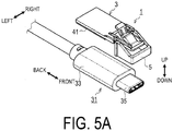
- the connector fixture 1 thus configured is attached to a first connector 31 as illustrated in FIGS. 5A , 5B , and 5C .
- the first connector 31 is a plug connector conforming to Type-C of the USB (Universal Serial Bus).
- the first connector 31 includes a resin housing portion 33 and a metallic connecting portion 35 protruding from the housing portion 33.
- both the fixture body 3 and the positioning member 5 are attached to the first connector 31.
- the fixing portion 11 is fixed to the housing portion 33 of the first connector 31.
- a double-sided tape 41 is adhered to the fixing portion 11. The double-sided tape 41 can fix the fixing portion 11 to the housing portion 33 of the first connector 31.
- the relative position between the fixture body 3 and the first connector 31 is determined. Specifically, in the left-right direction, the relative position between the fixture body 3 and the first connector 31 is determined by fitting the connecting portion 35 of the first connector 31 into the positioning member 5 as illustrated in FIG. 6A .
- the connecting portion 35 of the first connector 31 is fitted into the positioning member 5, in the state where the first wall face 23A and the second wall face 23B are disposed with a space therebetween in the direction that is parallel to the left-right direction, and the connecting portion 35 protrudes in the direction that is parallel to the front-back direction, both ends of the connecting portion 35 in the left-right direction are sandwiched between the first wall face 23A and the second wall face 23B.
- the connecting portion 35 of the first connector 31 is shaped and dimensioned in conformity with the standard. Accordingly, unlike the housing portion 33 having indefinite shape and dimension, the connecting portion 35 can be tightly fitted between the first wall face 23A and the second wall face 23B of the positioning member 5. Further, since the connecting portion 35 of the first connector 31 is made of metal, the dimensional accuracy of the connecting portion 35 is higher than that of the resin housing portion 33. Therefore, the connecting portion 35 can be fitted into the positioning member 5, achieving positioning in the left-right direction with high accuracy.
- the relative position between the fixture body 3 and the first connector 31 can be determined by causing a first contact portion 17A and the second contact portion 17B to contact the front end of the housing portion 33 (see FIG. 6B .
- FIG. 6B illustrates the second contact portion 17B).
- the connector fixture 1 is attached to the first connector 31 as described above, and then, the positioning member 5 is separated from the fixture body 3 to detach the positioning member 5. Thereby, as illustrated in FIG. 5C , only the fixture body 3 remains in the first connector 31.
- the positioning member 5 can be separated from the fixture body 3 by swinging the positioning member 5 to break the first coupling portion 7A and the second coupling portion 7B.
- the first coupling portion 7A and the second coupling portion 7B become the thinnest and weakest at the places coupled to the fixture body 3.
- the first coupling portion 7A and the second coupling portion 7B are disposed at two respective places that are spaced in the left-right direction. Therefore, when an external force is applied to the positioning member 5, the first coupling portion 7A and the second coupling portion 7B are bent at the weakest places, and as a result, the positioning member 5 swings about the axis that is parallel to the left-right direction.
- the positioning member 5 swings one or more times, a load is applied to the weakest places of the first coupling portion 7A and the second coupling portion 7B, breaking the first coupling portion 7A and the second coupling portion 7B at said places.
- the connecting portion 35 of the first connector 31 is disposed between the first wall face 23A and the second wall face 23B of the positioning member 5, but the positioning member 5 swings about the axis that is parallel to the left-right direction and thus, the swinging of the positioning member 5 is not hindered by the connecting portion 35. Further, since the positioning member 5 is less likely to swing about the axis that is parallel to the up-down direction or the front-back direction, the positioning accuracy in the left-right direction can be improved.
- a second connector 51 is a receptacle connector that conforms to Type-C of the USB.
- the second connector 51 is mounted on an electronic circuit board 53.
- the electronic circuit board 53 is disposed inside a panel 55 that constitutes the exterior of a device including the second connector 51.
- the panel 55 has an opening 57.
- the second connector 51 is fitted into a part of the opening 57.
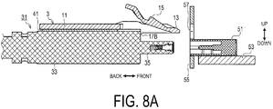
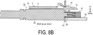
- the free end (the rear end in the figure) of the retaining portion 15 is pressed downward in the figure. This can release the retaining portion 15 hooked on the panel 55, thereby pulling out the first connector 31 and the fixture body 3 from the position illustrated in FIG. 8B to the position illustrated in FIG. 8A .
- the fixture body 3 can be attached to the first connector 31 by fixing the fixing portion 11 to the first connector 31.
- the retaining portion 15 is caught on the panel 55 of the device including the second connector 51, and prevents the first connector 31 from being displaced and detached from the second connector 51. Therefore, use of the fixture body 3 can prevent the first connector 31 from being detached from the second connector 51.
- the relative position between the fixture body 3 and the first connector 31 can be determined in the left-right direction by the positioning member 5, in the front-back direction by the first contact portion 17A and the second contact portion 17B, and in the up-down direction by the fixing portion 11. Accordingly, as compared with the case where positioning cannot be performed in any one or more of the left-right direction, the front-back direction, and the up-down direction, the fixture body 3 can be accurately positioned and attached to the first connector 31.
- the positioning member 5 can be detached by separating the positioning member 5 from the fixture body 3 in the state where the fixing portion 11 is fixed to the first connector 31.
- the structure attached to the first connector 31 can be made compact.
- the positioning member 5 does not get in the way. Therefore, even the positioning member 5 that would become an obstacle when the first connector 31 is connected to the second connector 51 unless detached may be used without any problem.
- the exemplary embodiment has been used to describe the connector fixture 1, but should not be construed to be any more than an example of one aspect of the present disclosure.
- the present disclosure is not limited to the exemplary embodiment described above and can be embodied in various forms without departing from the technical concept of the present disclosure.
- the fixing portion 11 is configured to be fixed to the first connector 31 with the double-sided tape 41.
- the fixing portion 11 may be configured to be fixed to the first connector 31 with fixing means other than the double-sided tape 41.
- an adhesive may be used in place of the double-sided tape 41.
- the housing portion 33 of the first connector 31 can be designed specifically for the connector fixture 1, the fixing portion 11 and the housing portion 33 of the first connector 31 may be provided with mutually engageable engaging mechanisms.
- the fixture body 3 and the first connector 31 are positioned in the left-right direction by the positioning member 5 and however, may be also positioned in the up-down direction and the front-back direction by the positioning member 5.
- a convex portion 61 that fits into the connecting portion 35 of the first connector 31 can be provided on the positioning member 5, and the first fixture body 3 and the first connector 31 can be positioned in the up-down direction and the front-back direction by the convex portion 61.
- first contact portion 17A and the second contact portion 17B are described as an example of the contact portion in the present disclosure.
- the number of the contact portion is not limited to two, and may be one or three or more.
- the plug connector and the receptacle connector that conform to Type-C of the USB are exemplified as examples of the first connector and the second connector in the present disclosure.
- these connectors may be any other form of connector.
- a function realized by a single constituent element in each the above-described embodiments may instead be realized by a plurality of constituent elements. Additionally, a function realized by a plurality of constituent elements may instead be realized by a single constituent element. Parts of the configurations in the above-described embodiments may be omitted. At least part of the configuration of one of the above-described embodiments may be added to or replace the configuration of another of the above-described embodiments.
- the connector fixture of the present disclosure may be further provided with configurations such as those given below.
- the first connector may include a housing portion and a metal connecting portion protruding from the housing portion, and when the connecting portion is connected to the second connector, the connecting portion may be inserted into the second connector.
- the positioning member may be configured to contact the connecting portion when the fixture body is attached to the first connector, to determine relative position between the fixture body and the first connector in the x-axis direction.
- the positioning member may have two wall faces opposed to each other with a space therebetween, and in the state where the two wall faces are disposed with the space in the direction that is parallel to the x-axis direction and the connecting portion protrudes in the direction that is parallel to the y-axis direction, the positioning member is configured to sandwich both ends of the connecting portion in the x-axis direction between the two wall faces to determine relative position between the fixture body and the first connector in the x-axis direction.
- the positioning member may be configured to be swingably coupled to the fixture body via at least one coupling portion integrally molded with the fixture body and the positioning member using a resin material, to swing the positioning member to break the coupling portion, being separable from the fixture body.
- a first coupling portion and a second coupling portion may be provided as at least one coupling portion.
- the first coupling portion and the second coupling portion may be disposed with a space therebetween in the x-axis direction such that the swinging center of the positioning member is parallel to the x-axis direction.
Abstract
Description
- This application claims the benefit of Japanese Patent Application No.
2018-200072 filed October 24, 2018 - Patent Office, and the entire disclosure of Japanese Patent Application No.
2018-200072 - The present disclosure relates to a connector fixture.
- A lock claw replacing jig, which is used as an alternative when a lock claw of a modular plug (corresponding to an example of the first connector in the present disclosure) has been broken, has been proposed (see, for example, Japanese Patent Application Laid-Open No.
2005-142127 - However, in the lock claw replacing jig (1) described above, when the fixing plate portion (1a) is fixed to the upper surface of the plug body (3a), it is not easy to set the fixing plate portion at an optimum position on the upper surface of the plug body.
- More specifically, in the above-described lock claw replacing jig, a front end of the fixing plate portion is fixed so as to abut against the base end portion (3b). Thus, the fixing plate portion can be positioned in a direction that is parallel to the plug insertion direction (corresponding to the y-axis direction in the present disclosure). However, the fixing plate portion cannot be positioned in the direction that is orthogonal to the plug insertion direction (corresponding to the x-axis direction in the present disclosure). Therefore, there is a possibility that the lock claw replacing jig is deviated from the center of the plug in the direction that is orthogonal to the plug insertion direction. In this case, if the deviation becomes large, the lock claw replacing jig may not be hooked on the structure on the modular jack side, or the locking claw replacement jig may become an obstacle, preventing the modular plug from being inserted into the modular jack.
- In one aspect of the present disclosure, it is desirable to provide a connector fixture that enables an easy positioning operation for a connector when the connector fixture is fixed to the connector.
- One aspect of the present disclosure is a connector fixture, which includes a fixture body and a positioning member. The fixture body includes a fixing portion, a retaining portion, and a contact portion. The fixing portion is configured to be fixed to a first connector when the fixture body is attached to the first connector, and to determine relative position between the fixture body and the first connector in a z-axis direction among x-axis direction, y-axis direction, and z-axis direction, the directions being orthogonal to each other, when the fixing portion is fixed to the first connector. When said first connector is connected to a second connector in a state where the fixture body is attached to the first connector, the retaining portion is configured to be hooked on a place of a device including the second connector, preventing the first connector from being displaced and detached from the second connector. The contact portion is configured to contact the first connector when the fixture body is attached to the first connector, to determine relative position between the fixture body and the first connector in the y-axis direction. The positioning member is configured to contact the first connector when the fixture body is attached to the first connector, to determine relative position between the fixture body and the first connector in the x-axis direction. The positioning member is configured to be separable from the fixture body.
- According to the connector fixture configured as described above, the fixture body can be attached to the first connector by fixing the fixing portion to the first connector. When said first connector is connected to the second connector in the state where the fixture body is attached to the first connector, the retaining portion is hooked on the place of the device including the second connector, preventing the first connector from being displaced and detached from the second connector. Therefore, use of the fixture body can prevent the first connector from being detached from the second connector.
- Further, when the fixture body is attached to the first connector, the relative position between the fixture body and the first connector can be determined in the x-axis direction by the positioning member, in the y-axis direction by the contact portion, and in the z-axis direction by the fixing portion. Accordingly, as compared with the case where positioning cannot be performed in any one or more of the x-axis direction, the y-axis direction, and the z-axis direction, the fixture body can be accurately positioned and attached to the first connector.
- Furthermore, the positioning member can be separated from the fixture body. For this reason, once the fixing portion is fixed to the first connector, the positioning member can be separated from the fixture body to detach the positioning member. Thus, as compared with the case where the positioning member cannot be detached, the structure attached to the first connector can be made compact. In addition, in a case where the positioning member is detached, to connect the first connector to the second connector, the positioning member does not become an obstacle. In other words, even the positioning member that would become an obstacle when the first connector is connected to the second connector unless detached may be used without any problem. Therefore, the positioning member can be disposed at any desired position without considering whether or not the positioning member becomes an obstacle when the first connector is connected to the second connector.
- The invention will be described with reference to the accompanying drawings, wherein like numbers reference like elements.
-
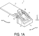
FIG. 1A is a perspective view of a connector fixture when viewed from the upper left front.FIG. 1B is a perspective view of the connector fixture when viewed from the lower right rear. -
FIG. 2A is a plan view of the connector fixture.FIG. 2B is a bottom view of the connector fixture. -
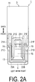
FIG. 3A is a front view of a connector fixture.FIG. 3B is a left side view of the connector fixture.FIG. 3C is a rear view of the connector fixture. -
FIG. 4A is a cross-sectional view taken along a line IVA-IVA inFIG. 3A .FIG. 4B is a cross-sectional view taken along a line IVB-IVB inFIG. 3A . -
FIG. 5A is a perspective view illustrating a first connector and the connector fixture.FIG. 5B is a perspective view illustrating a state where the connector fixture is attached to the first connector.FIG. 5C is a perspective view illustrating a state where a positioning member is detached from the connector fixture attached to the first connector. -
FIG. 6A is a bottom view illustrating a state where the positioning member of the connector fixture is in contact with a connecting portion of the first connector.FIG. 6A is a longitudinal sectional view illustrating a state where a contact portion of the connector fixture is in contact with a housing portion of the first connector. -
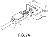
FIG. 7A is a perspective view illustrating a state before the first connector with the fixture body attached is connected to the second connector.FIG. 7B is a perspective view illustrating a state after the first connector with the fixture body attached has been connected to the second connector. -
FIG. 8A is a longitudinal sectional view illustrating a state before the first connector with the fixture body attached is attached is connected to the second connector.FIG. 8B is a perspective view illustrating a state after the first connector with the fixture body attached has been connected to the second connector. -
FIG. 9 is a longitudinal sectional view illustrating another example of the positioning member. - The connector fixture described above will be described below according to exemplary embodiments. In the present embodiment, the description will be made using the front, back, left, right, top, and bottom directions illustrated in the drawings. These directions each are a relative direction. The direction in which portions of the connector fixture in the front view (see
FIG. 3A ) are oriented is defined as forward, the direction in which portions of the connector fixture in the rear view (seeFIG. 3C ) are oriented is defined as backward, the direction in which portions of the connector fixture in the left side view (FIG. 3B ) are oriented is defined as leftward, the direction in which portions of the connector fixture in the right side view (not illustrated. The right side view and the left side view are symmetric) are oriented is defined as rightward, the direction in which portions of the connector fixture in the plan view (seeFIG. 2A ) are oriented is defined as upward, and the direction in which portions of the connector fixture in the bottom view (seeFIG. 2B ) are oriented is defined as downward. - However, it should be understood that these directions are defined only for the purpose of facilitating a simple description of the relative positional relationship of the constituents of the connector fixture. Therefore, for example, the direction in which the connector fixture is oriented in use is undefined. The left-right direction in the present embodiment corresponds to the x-axis direction in the present disclosure, the front-back direction in the present embodiment corresponds to the y-axis direction in the present disclosure, and the up-down direction in the present embodiment corresponds to the z-axis direction.
- As illustrated in
FIGS. 1A ,1B ,2A ,2B ,3A ,3B , and3C , theconnector fixture 1 includes afixture body 3 and apositioning member 5. Thefixture body 3 and thepositioning member 5 are coupled to each other via afirst coupling portion 7A and asecond coupling portion 7B (thefirst coupling portion 7A and thesecond coupling portion 7B correspond to an example of a connecting portion in the present disclosure). The portions constituting theconnector fixture 1 are integrally molded of a resin material. Thefixture body 3 includes a fixingportion 11, asupport portion 13, a retainingportion 15, afirst contact portion 17A, and asecond contact portion 17B (thefirst contact portion 17A and thesecond contact portion 17B correspond to an example of a contact portion in the present disclosure). - The fixing
portion 11 is configured as a flat plate having a thickness in the up-down direction. Thesupport portion 13 protrudes forward from a front end of the fixingportion 11. Thefirst contact portion 17A and thesecond contact portion 17B are provided below thesupport portion 13. As illustrated inFIG. 4A , the retainingportion 15 extends obliquely upward and rearward from the vicinity of a front end of thesupport portion 13. The retainingportion 15 has a front end connected to thesupport portion 13 as a fixed end, and a rear end as a free end, and is supported such that the free end is swingable about the fixed end in the up-down direction. - As illustrated in
FIGS. 2A ,3A ,3B , and3C ,ribs portion 11 and thesupport portion 13. As illustrated inFIGS. 2A ,3A , and3B ,ribs portion 15. As illustrated inFIGS. 2B ,3B , and3C ,ribs portion 15. Theseribs 21A to 21J enhance the bending rigidity of the places where theribs 21A to 21J are provided. - As illustrated in
FIGS. 2A ,2B , and3C , the positioningmember 5 includes afirst wall face 23A and asecond wall face 23B, which are opposed to each other with a space therebetween in the left-right direction. As illustrated inFIGS. 2A ,2B ,3B , and4B , thefirst coupling portion 7A and thesecond coupling portion 7B are tapered from one ends coupled to thepositioning member 5 to the other ends coupled to thefixture body 3. - The
connector fixture 1 thus configured is attached to afirst connector 31 as illustrated inFIGS. 5A ,5B , and5C . In the present embodiment, thefirst connector 31 is a plug connector conforming to Type-C of the USB (Universal Serial Bus). Thefirst connector 31 includes aresin housing portion 33 and a metallic connectingportion 35 protruding from thehousing portion 33. - When the
connector fixture 1 is attached to thefirst connector 31, first, as illustrated inFIG. 5B , both thefixture body 3 and thepositioning member 5 are attached to thefirst connector 31. At this time, the fixingportion 11 is fixed to thehousing portion 33 of thefirst connector 31. In the present embodiment, a double-sided tape 41 is adhered to the fixingportion 11. The double-sided tape 41 can fix the fixingportion 11 to thehousing portion 33 of thefirst connector 31. - When the fixing
portion 11 is fixed to thefirst connector 31, the relative position between thefixture body 3 and thefirst connector 31 is determined. Specifically, in the left-right direction, the relative position between thefixture body 3 and thefirst connector 31 is determined by fitting the connectingportion 35 of thefirst connector 31 into thepositioning member 5 as illustrated inFIG. 6A . When the connectingportion 35 of thefirst connector 31 is fitted into thepositioning member 5, in the state where the first wall face 23A and thesecond wall face 23B are disposed with a space therebetween in the direction that is parallel to the left-right direction, and the connectingportion 35 protrudes in the direction that is parallel to the front-back direction, both ends of the connectingportion 35 in the left-right direction are sandwiched between the first wall face 23A and thesecond wall face 23B. - The connecting
portion 35 of thefirst connector 31 is shaped and dimensioned in conformity with the standard. Accordingly, unlike thehousing portion 33 having indefinite shape and dimension, the connectingportion 35 can be tightly fitted between the first wall face 23A and thesecond wall face 23B of thepositioning member 5. Further, since the connectingportion 35 of thefirst connector 31 is made of metal, the dimensional accuracy of the connectingportion 35 is higher than that of theresin housing portion 33. Therefore, the connectingportion 35 can be fitted into thepositioning member 5, achieving positioning in the left-right direction with high accuracy. - Further, in the front-back direction, the relative position between the
fixture body 3 and thefirst connector 31 can be determined by causing afirst contact portion 17A and thesecond contact portion 17B to contact the front end of the housing portion 33 (seeFIG. 6B . However,FIG. 6B illustrates thesecond contact portion 17B). Once the relative position between thefixture body 3 and thefirst connector 31 is determined positioned in the left-right direction and the front-back direction as described above, by fixing the fixingportion 11 to thefirst connector 31 in this state, the relative position between thefixture body 3 and thefirst connector 31 can be determined by the fixingportion 11 in the up-down direction as well. - The
connector fixture 1 is attached to thefirst connector 31 as described above, and then, the positioningmember 5 is separated from thefixture body 3 to detach thepositioning member 5. Thereby, as illustrated inFIG. 5C , only thefixture body 3 remains in thefirst connector 31. In the present embodiment, the positioningmember 5 can be separated from thefixture body 3 by swinging thepositioning member 5 to break thefirst coupling portion 7A and thesecond coupling portion 7B. - In more detail, in the present embodiment, as described above, the
first coupling portion 7A and thesecond coupling portion 7B become the thinnest and weakest at the places coupled to thefixture body 3. In addition, thefirst coupling portion 7A and thesecond coupling portion 7B are disposed at two respective places that are spaced in the left-right direction. Therefore, when an external force is applied to thepositioning member 5, thefirst coupling portion 7A and thesecond coupling portion 7B are bent at the weakest places, and as a result, the positioningmember 5 swings about the axis that is parallel to the left-right direction. - Therefore, in a case where the
positioning member 5 swings one or more times, a load is applied to the weakest places of thefirst coupling portion 7A and thesecond coupling portion 7B, breaking thefirst coupling portion 7A and thesecond coupling portion 7B at said places. Note that the connectingportion 35 of thefirst connector 31 is disposed between the first wall face 23A and thesecond wall face 23B of thepositioning member 5, but thepositioning member 5 swings about the axis that is parallel to the left-right direction and thus, the swinging of thepositioning member 5 is not hindered by the connectingportion 35. Further, since thepositioning member 5 is less likely to swing about the axis that is parallel to the up-down direction or the front-back direction, the positioning accuracy in the left-right direction can be improved. - As illustrated in
FIGS. 7A and7B , thefirst connector 31 with thefixture body 3 attached is connected to thesecond connector 51. In the present embodiment, asecond connector 51 is a receptacle connector that conforms to Type-C of the USB. Thesecond connector 51 is mounted on anelectronic circuit board 53. Theelectronic circuit board 53 is disposed inside apanel 55 that constitutes the exterior of a device including thesecond connector 51. As illustrated inFIG. 7A , thepanel 55 has anopening 57. Thesecond connector 51 is fitted into a part of theopening 57. - In connecting the
first connector 31 to thesecond connector 51, when thefirst connector 31 and thefixture body 3 move from a position illustrated inFIG. 8A to a position illustrated inFIG. 8B , a part of thefixture body 3 on the front end side enters into thepanel 55 through theopening 57. At this time, the retainingportion 15 contacts with thepanel 55 at the upper side of theopening 57 and elastically deforms. The part entered into thepanel 55 is hooked on the inner side thepanel 55. In this state, the retainingportion 15 prevents thefirst connector 31 from being displaced and detached from thesecond connector 51. - To detach the
first connector 31 from thesecond connector 51, the free end (the rear end in the figure) of the retainingportion 15 is pressed downward in the figure. This can release the retainingportion 15 hooked on thepanel 55, thereby pulling out thefirst connector 31 and thefixture body 3 from the position illustrated inFIG. 8B to the position illustrated inFIG. 8A . - As described above, in the
connector fixture 1, thefixture body 3 can be attached to thefirst connector 31 by fixing the fixingportion 11 to thefirst connector 31. When thefirst connector 31 is connected to thesecond connector 51 in the state where thefixture body 3 is attached to thefirst connector 31, the retainingportion 15 is caught on thepanel 55 of the device including thesecond connector 51, and prevents thefirst connector 31 from being displaced and detached from thesecond connector 51. Therefore, use of thefixture body 3 can prevent thefirst connector 31 from being detached from thesecond connector 51. - Further, when the
fixture body 3 is attached to thefirst connector 31, the relative position between thefixture body 3 and thefirst connector 31 can be determined in the left-right direction by the positioningmember 5, in the front-back direction by thefirst contact portion 17A and thesecond contact portion 17B, and in the up-down direction by the fixingportion 11. Accordingly, as compared with the case where positioning cannot be performed in any one or more of the left-right direction, the front-back direction, and the up-down direction, thefixture body 3 can be accurately positioned and attached to thefirst connector 31. - Furthermore, the positioning
member 5 can be detached by separating thepositioning member 5 from thefixture body 3 in the state where the fixingportion 11 is fixed to thefirst connector 31. Thus, as compared with the case where thepositioning member 5 cannot be detached, the structure attached to thefirst connector 31 can be made compact. In addition, in a case where thepositioning member 5 is detached, to connect thefirst connector 31 to thesecond connector 51, the positioningmember 5 does not get in the way. Therefore, even thepositioning member 5 that would become an obstacle when thefirst connector 31 is connected to thesecond connector 51 unless detached may be used without any problem. - The exemplary embodiment has been used to describe the
connector fixture 1, but should not be construed to be any more than an example of one aspect of the present disclosure. In other words, the present disclosure is not limited to the exemplary embodiment described above and can be embodied in various forms without departing from the technical concept of the present disclosure. - For example, in the above-described embodiment, the fixing
portion 11 is configured to be fixed to thefirst connector 31 with the double-sided tape 41. However, the fixingportion 11 may be configured to be fixed to thefirst connector 31 with fixing means other than the double-sided tape 41. For example, in place of the double-sided tape 41, an adhesive may be used. Alternatively, if thehousing portion 33 of thefirst connector 31 can be designed specifically for theconnector fixture 1, the fixingportion 11 and thehousing portion 33 of thefirst connector 31 may be provided with mutually engageable engaging mechanisms. - In the above embodiment, the
fixture body 3 and thefirst connector 31 are positioned in the left-right direction by the positioningmember 5 and however, may be also positioned in the up-down direction and the front-back direction by the positioningmember 5. For example, as illustrated inFIG. 9 , aconvex portion 61 that fits into the connectingportion 35 of thefirst connector 31 can be provided on thepositioning member 5, and thefirst fixture body 3 and thefirst connector 31 can be positioned in the up-down direction and the front-back direction by theconvex portion 61. - Moreover, in the above-described embodiment, the
first contact portion 17A and thesecond contact portion 17B are described as an example of the contact portion in the present disclosure. However, the number of the contact portion is not limited to two, and may be one or three or more. - In the above-described embodiment, the plug connector and the receptacle connector that conform to Type-C of the USB are exemplified as examples of the first connector and the second connector in the present disclosure. However, these connectors may be any other form of connector.
- Note that a function realized by a single constituent element in each the above-described embodiments may instead be realized by a plurality of constituent elements. Additionally, a function realized by a plurality of constituent elements may instead be realized by a single constituent element. Parts of the configurations in the above-described embodiments may be omitted. At least part of the configuration of one of the above-described embodiments may be added to or replace the configuration of another of the above-described embodiments. Supplementary Description
- Note that, as clear from the exemplary embodiments described above, the connector fixture of the present disclosure may be further provided with configurations such as those given below.
- In one aspect of the present disclosure, the first connector may include a housing portion and a metal connecting portion protruding from the housing portion, and when the connecting portion is connected to the second connector, the connecting portion may be inserted into the second connector. The positioning member may be configured to contact the connecting portion when the fixture body is attached to the first connector, to determine relative position between the fixture body and the first connector in the x-axis direction.
- In one aspect of the present disclosure, the positioning member may have two wall faces opposed to each other with a space therebetween, and in the state where the two wall faces are disposed with the space in the direction that is parallel to the x-axis direction and the connecting portion protrudes in the direction that is parallel to the y-axis direction, the positioning member is configured to sandwich both ends of the connecting portion in the x-axis direction between the two wall faces to determine relative position between the fixture body and the first connector in the x-axis direction.
- In one aspect of the present disclosure, the positioning member may be configured to be swingably coupled to the fixture body via at least one coupling portion integrally molded with the fixture body and the positioning member using a resin material, to swing the positioning member to break the coupling portion, being separable from the fixture body.
- In one aspect of the present disclosure, a first coupling portion and a second coupling portion may be provided as at least one coupling portion. The first coupling portion and the second coupling portion may be disposed with a space therebetween in the x-axis direction such that the swinging center of the positioning member is parallel to the x-axis direction.
Claims (5)
- A connector fixture comprising a fixture body and a positioning member, wherein
the fixture body includes a fixing portion, a retaining portion, and a contact portion,
the fixing portion is configured to be fixed to a first connector when the fixture body is attached to the first connector, and to determine relative position between the fixture body and the first connector in a z-axis direction among x-axis direction, y-axis direction, and z-axis direction, the directions being orthogonal to each other, when the fixing portion is fixed to the first connector,
the retaining portion is configured to be hooked on a portion of a device including a second connector when the first connector is connected to the second connector in a state where the fixture body is attached to the first connector, preventing the first connector from being displaced and detached from the second connector,
the contact portion is configured to contact the first connector when the fixture body is attached to the first connector, to determine relative position between the fixture body and the first connector in the y-axis direction,
the positioning member is configured to contact the first connector when the fixture body is attached to the first connector, to determine relative position between the fixture body and the first connector in the x-axis direction, and
the positioning member is configured to be separable from the fixture body. - The connector fixture according to claim 1, wherein
the first connector has a housing portion and a metallic connecting portion protruding from the housing portion, the connecting portion being configured to be inserted into the second connector when the first connector is connected to the second connector, and
the positioning member is configured to contact the connecting portion when the fixture body is attached to the first connector, and to determine relative position between the fixture body and the first connector in the x-axis direction. - The connector fixture according to claim 2, wherein
the positioning member has two wall faces opposed to each other with a space, and in a state where the two wall faces are disposed with the space in a direction that is parallel to the x-axis direction and the connecting portion protrudes in a direction that is parallel to the y-axis direction, the positioning member is configured to sandwich both ends of the connecting portion in the x-axis direction between the two wall faces to determine relative position between the fixture body and the first connector in the x-axis direction. - The connector fixture according to claim 3, wherein
the positioning member is configured to be swingably coupled to the fixture body via at least one coupling portion integrally molded with the fixture body and the positioning member using a resin material, and to swing the positioning member to break the coupling portion, being separable from the fixture body. - The connector fixture according to claim 4, wherein
a first coupling portion and a second coupling portion are provided as the at least one coupling portion, and
the first coupling portion and the second coupling portion are configured to be disposed with a space therebetween in the x-axis direction such that the swinging center of the positioning member is parallel to the x-axis direction.
Applications Claiming Priority (1)
| Application Number | Priority Date | Filing Date | Title |
|---|---|---|---|
| JP2018200072A JP7014424B2 (en) | 2018-10-24 | 2018-10-24 | Connector fixture |
Publications (2)
| Publication Number | Publication Date |
|---|---|
| EP3644453A1 true EP3644453A1 (en) | 2020-04-29 |
| EP3644453B1 EP3644453B1 (en) | 2022-02-09 |
Family
ID=68342751
Family Applications (1)
| Application Number | Title | Priority Date | Filing Date |
|---|---|---|---|
| EP19205007.8A Active EP3644453B1 (en) | 2018-10-24 | 2019-10-24 | Connector fixture |
Country Status (3)
| Country | Link |
|---|---|
| US (1) | US10916886B2 (en) |
| EP (1) | EP3644453B1 (en) |
| JP (1) | JP7014424B2 (en) |
Families Citing this family (2)
| Publication number | Priority date | Publication date | Assignee | Title |
|---|---|---|---|---|
| JP6255190B2 (en) * | 2013-08-30 | 2017-12-27 | ダンロップスポーツ株式会社 | Iron type golf club head and golf club set including the same |
| JP2021197208A (en) * | 2020-06-09 | 2021-12-27 | 日本航空電子工業株式会社 | Locator, harness, and manufacturing method of harness |
Citations (4)
| Publication number | Priority date | Publication date | Assignee | Title |
|---|---|---|---|---|
| JPH02108276U (en) * | 1989-02-16 | 1990-08-28 | ||
| JP2005142127A (en) | 2003-11-10 | 2005-06-02 | Nec Corp | Locking claw replacing jig |
| WO2010047345A1 (en) * | 2008-10-21 | 2010-04-29 | 木谷電器株式会社 | Connector device adapted to connect electric power cables together and used in solar energy power generation system |
| WO2017086259A1 (en) * | 2015-11-20 | 2017-05-26 | 北川工業株式会社 | Connector fixture |
Family Cites Families (11)
| Publication number | Priority date | Publication date | Assignee | Title |
|---|---|---|---|---|
| JP3064910U (en) | 1999-06-15 | 2000-01-28 | アイコム株式会社 | Plug repair equipment for modular connectors |
| JP2001345140A (en) * | 2000-05-31 | 2001-12-14 | Yazaki Corp | Connector with rear holder and its temporary lock device |
| JP2005142147A (en) * | 2003-10-15 | 2005-06-02 | Alps Electric Co Ltd | Thermally-actuated switch and its manufacturing method |
| JP2005332671A (en) | 2004-05-19 | 2005-12-02 | Internatl Business Mach Corp <Ibm> | Plug latch for connector and restoration method of latch function for broken plug |
| JP4883726B2 (en) | 2009-05-11 | 2012-02-22 | ヒロセ電機株式会社 | Modular plug |
| CN101901991A (en) | 2009-05-27 | 2010-12-01 | 鸿富锦精密工业(深圳)有限公司 | Crystal head and snap-in device thereof |
| US9103478B2 (en) * | 2011-12-09 | 2015-08-11 | Mercury Plastics, Inc. | Quick-connect tube coupling |
| US10048447B2 (en) * | 2013-10-31 | 2018-08-14 | CommScope Connectivity Belgium BVBA | Fiber optic connection system |
| US9913401B2 (en) * | 2014-05-29 | 2018-03-06 | Arris Enterprises Llc | Pivotable fan assembly and associated systems |
| WO2016081973A1 (en) * | 2014-11-24 | 2016-06-02 | Milner Wayne Russell | Mounting fixture of a connection fixture |
| JP6818418B2 (en) | 2016-02-26 | 2021-01-20 | ヒロセ電機株式会社 | Connector and connector device with shell |
-
2018
- 2018-10-24 JP JP2018200072A patent/JP7014424B2/en active Active
-
2019
- 2019-10-23 US US16/661,257 patent/US10916886B2/en active Active
- 2019-10-24 EP EP19205007.8A patent/EP3644453B1/en active Active
Patent Citations (4)
| Publication number | Priority date | Publication date | Assignee | Title |
|---|---|---|---|---|
| JPH02108276U (en) * | 1989-02-16 | 1990-08-28 | ||
| JP2005142127A (en) | 2003-11-10 | 2005-06-02 | Nec Corp | Locking claw replacing jig |
| WO2010047345A1 (en) * | 2008-10-21 | 2010-04-29 | 木谷電器株式会社 | Connector device adapted to connect electric power cables together and used in solar energy power generation system |
| WO2017086259A1 (en) * | 2015-11-20 | 2017-05-26 | 北川工業株式会社 | Connector fixture |
Also Published As
| Publication number | Publication date |
|---|---|
| JP2020068115A (en) | 2020-04-30 |
| EP3644453B1 (en) | 2022-02-09 |
| JP7014424B2 (en) | 2022-02-01 |
| US10916886B2 (en) | 2021-02-09 |
| US20200194933A1 (en) | 2020-06-18 |
Similar Documents
| Publication | Publication Date | Title |
|---|---|---|
| JP4726737B2 (en) | Auxiliary release releasing device for optical connector and printed circuit board device | |
| CN103986014B (en) | Usb socket | |
| EP3644453B1 (en) | Connector fixture | |
| JP2012013913A (en) | Optical connector | |
| EP2833484A1 (en) | Electric wire-to-substrate connector | |
| CN111009757B (en) | Connector assembly | |
| CN112771729B (en) | Connector with a locking member | |
| WO2018012243A1 (en) | Connector | |
| JP6782448B2 (en) | USB outlet | |
| JP2008251311A (en) | Electric connector assembly | |
| JP2008128460A (en) | Locking structure | |
| JP6890275B2 (en) | USB outlet | |
| JP4958185B2 (en) | Connector and electronic device | |
| JP2019129137A (en) | Connector, mating connector, and connector assembly | |
| JP7068252B2 (en) | Electrical junction box unit | |
| KR20110014270A (en) | Plug connector for flat cable | |
| JP6089381B2 (en) | USB outlet | |
| JP4223033B2 (en) | Panel mounting connector | |
| JP4274757B2 (en) | Unit device housing | |
| JP4403951B2 (en) | Electronics | |
| JP6731647B2 (en) | USB outlet | |
| JP6811413B2 (en) | USB outlet | |
| JP3798197B2 (en) | Wiring board connector assembly structure | |
| JP6089379B2 (en) | USB outlet | |
| JP2021132215A (en) | USB outlet |
Legal Events
| Date | Code | Title | Description |
|---|---|---|---|
| PUAI | Public reference made under article 153(3) epc to a published international application that has entered the european phase |
Free format text: ORIGINAL CODE: 0009012 |
|
| STAA | Information on the status of an ep patent application or granted ep patent |
Free format text: STATUS: REQUEST FOR EXAMINATION WAS MADE |
|
| 17P | Request for examination filed |
Effective date: 20191024 |
|
| AK | Designated contracting states |
Kind code of ref document: A1 Designated state(s): AL AT BE BG CH CY CZ DE DK EE ES FI FR GB GR HR HU IE IS IT LI LT LU LV MC MK MT NL NO PL PT RO RS SE SI SK SM TR |
|
| AX | Request for extension of the european patent |
Extension state: BA ME |
|
| GRAP | Despatch of communication of intention to grant a patent |
Free format text: ORIGINAL CODE: EPIDOSNIGR1 |
|
| STAA | Information on the status of an ep patent application or granted ep patent |
Free format text: STATUS: GRANT OF PATENT IS INTENDED |
|
| INTG | Intention to grant announced |
Effective date: 20211001 |
|
| GRAS | Grant fee paid |
Free format text: ORIGINAL CODE: EPIDOSNIGR3 |
|
| GRAA | (expected) grant |
Free format text: ORIGINAL CODE: 0009210 |
|
| STAA | Information on the status of an ep patent application or granted ep patent |
Free format text: STATUS: THE PATENT HAS BEEN GRANTED |
|
| AK | Designated contracting states |
Kind code of ref document: B1 Designated state(s): AL AT BE BG CH CY CZ DE DK EE ES FI FR GB GR HR HU IE IS IT LI LT LU LV MC MK MT NL NO PL PT RO RS SE SI SK SM TR |
|
| REG | Reference to a national code |
Ref country code: GB Ref legal event code: FG4D |
|
| REG | Reference to a national code |
Ref country code: CH Ref legal event code: EP Ref country code: AT Ref legal event code: REF Ref document number: 1468074 Country of ref document: AT Kind code of ref document: T Effective date: 20220215 |
|
| REG | Reference to a national code |
Ref country code: DE Ref legal event code: R096 Ref document number: 602019011457 Country of ref document: DE |
|
| REG | Reference to a national code |
Ref country code: IE Ref legal event code: FG4D |
|
| REG | Reference to a national code |
Ref country code: LT Ref legal event code: MG9D |
|
| REG | Reference to a national code |
Ref country code: NL Ref legal event code: MP Effective date: 20220209 |
|
| REG | Reference to a national code |
Ref country code: AT Ref legal event code: MK05 Ref document number: 1468074 Country of ref document: AT Kind code of ref document: T Effective date: 20220209 |
|
| PG25 | Lapsed in a contracting state [announced via postgrant information from national office to epo] |
Ref country code: SE Free format text: LAPSE BECAUSE OF FAILURE TO SUBMIT A TRANSLATION OF THE DESCRIPTION OR TO PAY THE FEE WITHIN THE PRESCRIBED TIME-LIMIT Effective date: 20220209 Ref country code: RS Free format text: LAPSE BECAUSE OF FAILURE TO SUBMIT A TRANSLATION OF THE DESCRIPTION OR TO PAY THE FEE WITHIN THE PRESCRIBED TIME-LIMIT Effective date: 20220209 Ref country code: PT Free format text: LAPSE BECAUSE OF FAILURE TO SUBMIT A TRANSLATION OF THE DESCRIPTION OR TO PAY THE FEE WITHIN THE PRESCRIBED TIME-LIMIT Effective date: 20220609 Ref country code: NO Free format text: LAPSE BECAUSE OF FAILURE TO SUBMIT A TRANSLATION OF THE DESCRIPTION OR TO PAY THE FEE WITHIN THE PRESCRIBED TIME-LIMIT Effective date: 20220509 Ref country code: NL Free format text: LAPSE BECAUSE OF FAILURE TO SUBMIT A TRANSLATION OF THE DESCRIPTION OR TO PAY THE FEE WITHIN THE PRESCRIBED TIME-LIMIT Effective date: 20220209 Ref country code: LT Free format text: LAPSE BECAUSE OF FAILURE TO SUBMIT A TRANSLATION OF THE DESCRIPTION OR TO PAY THE FEE WITHIN THE PRESCRIBED TIME-LIMIT Effective date: 20220209 Ref country code: HR Free format text: LAPSE BECAUSE OF FAILURE TO SUBMIT A TRANSLATION OF THE DESCRIPTION OR TO PAY THE FEE WITHIN THE PRESCRIBED TIME-LIMIT Effective date: 20220209 Ref country code: ES Free format text: LAPSE BECAUSE OF FAILURE TO SUBMIT A TRANSLATION OF THE DESCRIPTION OR TO PAY THE FEE WITHIN THE PRESCRIBED TIME-LIMIT Effective date: 20220209 Ref country code: BG Free format text: LAPSE BECAUSE OF FAILURE TO SUBMIT A TRANSLATION OF THE DESCRIPTION OR TO PAY THE FEE WITHIN THE PRESCRIBED TIME-LIMIT Effective date: 20220509 |
|
| PG25 | Lapsed in a contracting state [announced via postgrant information from national office to epo] |
Ref country code: PL Free format text: LAPSE BECAUSE OF FAILURE TO SUBMIT A TRANSLATION OF THE DESCRIPTION OR TO PAY THE FEE WITHIN THE PRESCRIBED TIME-LIMIT Effective date: 20220209 Ref country code: LV Free format text: LAPSE BECAUSE OF FAILURE TO SUBMIT A TRANSLATION OF THE DESCRIPTION OR TO PAY THE FEE WITHIN THE PRESCRIBED TIME-LIMIT Effective date: 20220209 Ref country code: GR Free format text: LAPSE BECAUSE OF FAILURE TO SUBMIT A TRANSLATION OF THE DESCRIPTION OR TO PAY THE FEE WITHIN THE PRESCRIBED TIME-LIMIT Effective date: 20220510 Ref country code: FI Free format text: LAPSE BECAUSE OF FAILURE TO SUBMIT A TRANSLATION OF THE DESCRIPTION OR TO PAY THE FEE WITHIN THE PRESCRIBED TIME-LIMIT Effective date: 20220209 Ref country code: AT Free format text: LAPSE BECAUSE OF FAILURE TO SUBMIT A TRANSLATION OF THE DESCRIPTION OR TO PAY THE FEE WITHIN THE PRESCRIBED TIME-LIMIT Effective date: 20220209 |
|
| PG25 | Lapsed in a contracting state [announced via postgrant information from national office to epo] |
Ref country code: IS Free format text: LAPSE BECAUSE OF FAILURE TO SUBMIT A TRANSLATION OF THE DESCRIPTION OR TO PAY THE FEE WITHIN THE PRESCRIBED TIME-LIMIT Effective date: 20220609 |
|
| PG25 | Lapsed in a contracting state [announced via postgrant information from national office to epo] |
Ref country code: SM Free format text: LAPSE BECAUSE OF FAILURE TO SUBMIT A TRANSLATION OF THE DESCRIPTION OR TO PAY THE FEE WITHIN THE PRESCRIBED TIME-LIMIT Effective date: 20220209 Ref country code: SK Free format text: LAPSE BECAUSE OF FAILURE TO SUBMIT A TRANSLATION OF THE DESCRIPTION OR TO PAY THE FEE WITHIN THE PRESCRIBED TIME-LIMIT Effective date: 20220209 Ref country code: RO Free format text: LAPSE BECAUSE OF FAILURE TO SUBMIT A TRANSLATION OF THE DESCRIPTION OR TO PAY THE FEE WITHIN THE PRESCRIBED TIME-LIMIT Effective date: 20220209 Ref country code: EE Free format text: LAPSE BECAUSE OF FAILURE TO SUBMIT A TRANSLATION OF THE DESCRIPTION OR TO PAY THE FEE WITHIN THE PRESCRIBED TIME-LIMIT Effective date: 20220209 Ref country code: DK Free format text: LAPSE BECAUSE OF FAILURE TO SUBMIT A TRANSLATION OF THE DESCRIPTION OR TO PAY THE FEE WITHIN THE PRESCRIBED TIME-LIMIT Effective date: 20220209 Ref country code: CZ Free format text: LAPSE BECAUSE OF FAILURE TO SUBMIT A TRANSLATION OF THE DESCRIPTION OR TO PAY THE FEE WITHIN THE PRESCRIBED TIME-LIMIT Effective date: 20220209 |
|
| REG | Reference to a national code |
Ref country code: DE Ref legal event code: R097 Ref document number: 602019011457 Country of ref document: DE |
|
| PG25 | Lapsed in a contracting state [announced via postgrant information from national office to epo] |
Ref country code: AL Free format text: LAPSE BECAUSE OF FAILURE TO SUBMIT A TRANSLATION OF THE DESCRIPTION OR TO PAY THE FEE WITHIN THE PRESCRIBED TIME-LIMIT Effective date: 20220209 |
|
| PLBE | No opposition filed within time limit |
Free format text: ORIGINAL CODE: 0009261 |
|
| STAA | Information on the status of an ep patent application or granted ep patent |
Free format text: STATUS: NO OPPOSITION FILED WITHIN TIME LIMIT |
|
| 26N | No opposition filed |
Effective date: 20221110 |
|
| PG25 | Lapsed in a contracting state [announced via postgrant information from national office to epo] |
Ref country code: SI Free format text: LAPSE BECAUSE OF FAILURE TO SUBMIT A TRANSLATION OF THE DESCRIPTION OR TO PAY THE FEE WITHIN THE PRESCRIBED TIME-LIMIT Effective date: 20220209 |
|
| PG25 | Lapsed in a contracting state [announced via postgrant information from national office to epo] |
Ref country code: MC Free format text: LAPSE BECAUSE OF FAILURE TO SUBMIT A TRANSLATION OF THE DESCRIPTION OR TO PAY THE FEE WITHIN THE PRESCRIBED TIME-LIMIT Effective date: 20220209 |
|
| REG | Reference to a national code |
Ref country code: CH Ref legal event code: PL |
|
| REG | Reference to a national code |
Ref country code: BE Ref legal event code: MM Effective date: 20221031 |
|
| PG25 | Lapsed in a contracting state [announced via postgrant information from national office to epo] |
Ref country code: LU Free format text: LAPSE BECAUSE OF NON-PAYMENT OF DUE FEES Effective date: 20221024 |
|
| PG25 | Lapsed in a contracting state [announced via postgrant information from national office to epo] |
Ref country code: LI Free format text: LAPSE BECAUSE OF NON-PAYMENT OF DUE FEES Effective date: 20221031 Ref country code: IT Free format text: LAPSE BECAUSE OF FAILURE TO SUBMIT A TRANSLATION OF THE DESCRIPTION OR TO PAY THE FEE WITHIN THE PRESCRIBED TIME-LIMIT Effective date: 20220209 Ref country code: FR Free format text: LAPSE BECAUSE OF NON-PAYMENT OF DUE FEES Effective date: 20221031 Ref country code: CH Free format text: LAPSE BECAUSE OF NON-PAYMENT OF DUE FEES Effective date: 20221031 |
|
| PG25 | Lapsed in a contracting state [announced via postgrant information from national office to epo] |
Ref country code: BE Free format text: LAPSE BECAUSE OF NON-PAYMENT OF DUE FEES Effective date: 20221031 |
|
| PG25 | Lapsed in a contracting state [announced via postgrant information from national office to epo] |
Ref country code: IE Free format text: LAPSE BECAUSE OF NON-PAYMENT OF DUE FEES Effective date: 20221024 |
|
| PGFP | Annual fee paid to national office [announced via postgrant information from national office to epo] |
Ref country code: DE Payment date: 20231020 Year of fee payment: 5 |
|
| PG25 | Lapsed in a contracting state [announced via postgrant information from national office to epo] |
Ref country code: HU Free format text: LAPSE BECAUSE OF FAILURE TO SUBMIT A TRANSLATION OF THE DESCRIPTION OR TO PAY THE FEE WITHIN THE PRESCRIBED TIME-LIMIT; INVALID AB INITIO Effective date: 20191024 |