EP3644434A1 - Battery module in which cooling and assembly structure is simplified, and manufacturing method therefor - Google Patents
Battery module in which cooling and assembly structure is simplified, and manufacturing method therefor Download PDFInfo
- Publication number
- EP3644434A1 EP3644434A1 EP18871412.5A EP18871412A EP3644434A1 EP 3644434 A1 EP3644434 A1 EP 3644434A1 EP 18871412 A EP18871412 A EP 18871412A EP 3644434 A1 EP3644434 A1 EP 3644434A1
- Authority
- EP
- European Patent Office
- Prior art keywords
- cooling
- tray
- type secondary
- battery module
- secondary batteries
- Prior art date
- Legal status (The legal status is an assumption and is not a legal conclusion. Google has not performed a legal analysis and makes no representation as to the accuracy of the status listed.)
- Granted
Links
Images



Classifications
-
- H—ELECTRICITY
- H01—ELECTRIC ELEMENTS
- H01M—PROCESSES OR MEANS, e.g. BATTERIES, FOR THE DIRECT CONVERSION OF CHEMICAL ENERGY INTO ELECTRICAL ENERGY
- H01M10/00—Secondary cells; Manufacture thereof
- H01M10/60—Heating or cooling; Temperature control
- H01M10/61—Types of temperature control
- H01M10/613—Cooling or keeping cold
-
- H—ELECTRICITY
- H01—ELECTRIC ELEMENTS
- H01M—PROCESSES OR MEANS, e.g. BATTERIES, FOR THE DIRECT CONVERSION OF CHEMICAL ENERGY INTO ELECTRICAL ENERGY
- H01M10/00—Secondary cells; Manufacture thereof
- H01M10/60—Heating or cooling; Temperature control
- H01M10/64—Heating or cooling; Temperature control characterised by the shape of the cells
- H01M10/643—Cylindrical cells
-
- H—ELECTRICITY
- H01—ELECTRIC ELEMENTS
- H01M—PROCESSES OR MEANS, e.g. BATTERIES, FOR THE DIRECT CONVERSION OF CHEMICAL ENERGY INTO ELECTRICAL ENERGY
- H01M10/00—Secondary cells; Manufacture thereof
- H01M10/60—Heating or cooling; Temperature control
- H01M10/65—Means for temperature control structurally associated with the cells
- H01M10/653—Means for temperature control structurally associated with the cells characterised by electrically insulating or thermally conductive materials
-
- H—ELECTRICITY
- H01—ELECTRIC ELEMENTS
- H01M—PROCESSES OR MEANS, e.g. BATTERIES, FOR THE DIRECT CONVERSION OF CHEMICAL ENERGY INTO ELECTRICAL ENERGY
- H01M10/00—Secondary cells; Manufacture thereof
- H01M10/60—Heating or cooling; Temperature control
- H01M10/65—Means for temperature control structurally associated with the cells
- H01M10/655—Solid structures for heat exchange or heat conduction
- H01M10/6551—Surfaces specially adapted for heat dissipation or radiation, e.g. fins or coatings
-
- H—ELECTRICITY
- H01—ELECTRIC ELEMENTS
- H01M—PROCESSES OR MEANS, e.g. BATTERIES, FOR THE DIRECT CONVERSION OF CHEMICAL ENERGY INTO ELECTRICAL ENERGY
- H01M10/00—Secondary cells; Manufacture thereof
- H01M10/60—Heating or cooling; Temperature control
- H01M10/65—Means for temperature control structurally associated with the cells
- H01M10/655—Solid structures for heat exchange or heat conduction
- H01M10/6554—Rods or plates
-
- H—ELECTRICITY
- H01—ELECTRIC ELEMENTS
- H01M—PROCESSES OR MEANS, e.g. BATTERIES, FOR THE DIRECT CONVERSION OF CHEMICAL ENERGY INTO ELECTRICAL ENERGY
- H01M10/00—Secondary cells; Manufacture thereof
- H01M10/60—Heating or cooling; Temperature control
- H01M10/65—Means for temperature control structurally associated with the cells
- H01M10/655—Solid structures for heat exchange or heat conduction
- H01M10/6556—Solid parts with flow channel passages or pipes for heat exchange
-
- H—ELECTRICITY
- H01—ELECTRIC ELEMENTS
- H01M—PROCESSES OR MEANS, e.g. BATTERIES, FOR THE DIRECT CONVERSION OF CHEMICAL ENERGY INTO ELECTRICAL ENERGY
- H01M50/00—Constructional details or processes of manufacture of the non-active parts of electrochemical cells other than fuel cells, e.g. hybrid cells
- H01M50/20—Mountings; Secondary casings or frames; Racks, modules or packs; Suspension devices; Shock absorbers; Transport or carrying devices; Holders
- H01M50/204—Racks, modules or packs for multiple batteries or multiple cells
- H01M50/207—Racks, modules or packs for multiple batteries or multiple cells characterised by their shape
- H01M50/209—Racks, modules or packs for multiple batteries or multiple cells characterised by their shape adapted for prismatic or rectangular cells
-
- H—ELECTRICITY
- H01—ELECTRIC ELEMENTS
- H01M—PROCESSES OR MEANS, e.g. BATTERIES, FOR THE DIRECT CONVERSION OF CHEMICAL ENERGY INTO ELECTRICAL ENERGY
- H01M50/00—Constructional details or processes of manufacture of the non-active parts of electrochemical cells other than fuel cells, e.g. hybrid cells
- H01M50/20—Mountings; Secondary casings or frames; Racks, modules or packs; Suspension devices; Shock absorbers; Transport or carrying devices; Holders
- H01M50/204—Racks, modules or packs for multiple batteries or multiple cells
- H01M50/207—Racks, modules or packs for multiple batteries or multiple cells characterised by their shape
- H01M50/213—Racks, modules or packs for multiple batteries or multiple cells characterised by their shape adapted for cells having curved cross-section, e.g. round or elliptic
-
- H—ELECTRICITY
- H01—ELECTRIC ELEMENTS
- H01M—PROCESSES OR MEANS, e.g. BATTERIES, FOR THE DIRECT CONVERSION OF CHEMICAL ENERGY INTO ELECTRICAL ENERGY
- H01M50/00—Constructional details or processes of manufacture of the non-active parts of electrochemical cells other than fuel cells, e.g. hybrid cells
- H01M50/20—Mountings; Secondary casings or frames; Racks, modules or packs; Suspension devices; Shock absorbers; Transport or carrying devices; Holders
- H01M50/258—Modular batteries; Casings provided with means for assembling
-
- H—ELECTRICITY
- H01—ELECTRIC ELEMENTS
- H01M—PROCESSES OR MEANS, e.g. BATTERIES, FOR THE DIRECT CONVERSION OF CHEMICAL ENERGY INTO ELECTRICAL ENERGY
- H01M50/00—Constructional details or processes of manufacture of the non-active parts of electrochemical cells other than fuel cells, e.g. hybrid cells
- H01M50/20—Mountings; Secondary casings or frames; Racks, modules or packs; Suspension devices; Shock absorbers; Transport or carrying devices; Holders
- H01M50/262—Mountings; Secondary casings or frames; Racks, modules or packs; Suspension devices; Shock absorbers; Transport or carrying devices; Holders with fastening means, e.g. locks
- H01M50/264—Mountings; Secondary casings or frames; Racks, modules or packs; Suspension devices; Shock absorbers; Transport or carrying devices; Holders with fastening means, e.g. locks for cells or batteries, e.g. straps, tie rods or peripheral frames
-
- H—ELECTRICITY
- H01—ELECTRIC ELEMENTS
- H01M—PROCESSES OR MEANS, e.g. BATTERIES, FOR THE DIRECT CONVERSION OF CHEMICAL ENERGY INTO ELECTRICAL ENERGY
- H01M50/00—Constructional details or processes of manufacture of the non-active parts of electrochemical cells other than fuel cells, e.g. hybrid cells
- H01M50/20—Mountings; Secondary casings or frames; Racks, modules or packs; Suspension devices; Shock absorbers; Transport or carrying devices; Holders
- H01M50/271—Lids or covers for the racks or secondary casings
-
- H—ELECTRICITY
- H01—ELECTRIC ELEMENTS
- H01M—PROCESSES OR MEANS, e.g. BATTERIES, FOR THE DIRECT CONVERSION OF CHEMICAL ENERGY INTO ELECTRICAL ENERGY
- H01M10/00—Secondary cells; Manufacture thereof
- H01M10/60—Heating or cooling; Temperature control
- H01M10/62—Heating or cooling; Temperature control specially adapted for specific applications
- H01M10/625—Vehicles
-
- H—ELECTRICITY
- H01—ELECTRIC ELEMENTS
- H01M—PROCESSES OR MEANS, e.g. BATTERIES, FOR THE DIRECT CONVERSION OF CHEMICAL ENERGY INTO ELECTRICAL ENERGY
- H01M10/00—Secondary cells; Manufacture thereof
- H01M10/60—Heating or cooling; Temperature control
- H01M10/64—Heating or cooling; Temperature control characterised by the shape of the cells
- H01M10/647—Prismatic or flat cells, e.g. pouch cells
-
- H—ELECTRICITY
- H01—ELECTRIC ELEMENTS
- H01M—PROCESSES OR MEANS, e.g. BATTERIES, FOR THE DIRECT CONVERSION OF CHEMICAL ENERGY INTO ELECTRICAL ENERGY
- H01M2220/00—Batteries for particular applications
- H01M2220/20—Batteries in motive systems, e.g. vehicle, ship, plane
-
- Y—GENERAL TAGGING OF NEW TECHNOLOGICAL DEVELOPMENTS; GENERAL TAGGING OF CROSS-SECTIONAL TECHNOLOGIES SPANNING OVER SEVERAL SECTIONS OF THE IPC; TECHNICAL SUBJECTS COVERED BY FORMER USPC CROSS-REFERENCE ART COLLECTIONS [XRACs] AND DIGESTS
- Y02—TECHNOLOGIES OR APPLICATIONS FOR MITIGATION OR ADAPTATION AGAINST CLIMATE CHANGE
- Y02E—REDUCTION OF GREENHOUSE GAS [GHG] EMISSIONS, RELATED TO ENERGY GENERATION, TRANSMISSION OR DISTRIBUTION
- Y02E60/00—Enabling technologies; Technologies with a potential or indirect contribution to GHG emissions mitigation
- Y02E60/10—Energy storage using batteries
Definitions
- the present disclosure relates to a battery module, and more particularly, to a battery module to which a new assembling structure is applied to satisfy the cooling efficiency and the simplified assembling structure for secondary batteries simultaneously, and a method for manufacturing the battery module.
- a secondary battery cell includes positive and negative electrode current collectors, a separator, active materials and an electrolyte, and may be repeatedly charged and discharged by electrochemical reactions between components. Since the battery cells are densely provided in a compact space of a battery module, it is important to easily release the heat generated by each battery cell. Since the battery cell is charged and discharged due to an electrochemical reaction, if the heat of the battery module generated during the charging and discharging process is not effectively removed, heat accumulation occurs, which may promote the degradation of the battery module, and in more severe cases, cause ignition or explosion.
- a high-output large-capacity battery module and a battery pack having the battery module are required to have a cooling device for cooling battery cells included therein.
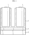
- FIG. 1 is a diagram schematically showing a cooling structure of a conventional battery module.
- the conventional battery module may include, for example, secondary battery cells 1, a housing 2 for accommodating and holding the secondary battery cells 1, a heatsink 3, and a thermal interface material (TIM) 4.
- TIM thermal interface material
- the housing 2 typically has a fixing structure capable of holding the plurality of secondary battery cells 1 individually.
- a cylindrical secondary battery may be inserted to constrain the secondary battery cells 1.
- a separate fixing frame may be used so that the fixing frame is assembled to the housing 2 in a state of holding the plurality of secondary battery cells 1 integrally.
- the housing 2 may be made of aluminum or aluminum alloy with excellent mechanical rigidity and heat dissipation performance.
- the heatsink 3 is a cooling device for suitably keeping the temperature of secondary battery cells during charging and discharging and may be disposed in contact with a lower portion of the housing 2.
- the heatsink 3 may be configured so that a coolant flows therein, and may absorb heat from the secondary battery cells 1 through the housing 2.
- the TIM 4 is disposed at an interface between the housing 2 and the heatsink 3 to reduce contact resistance between the housing 2 and the heatsink 3.
- the TIM 4 may employ a thermally conductive pad or resin.
- the present disclosure is designed to solve the problems of the related art, and therefore the present disclosure is directed to providing a battery module, which has a new cooling and assembling structure capable of satisfying the cooling efficiency and the simplified assembling structure for secondary batteries simultaneously, and a method for manufacturing the battery module.
- a battery module comprising: a plurality of can-type secondary batteries; a cooling tray formed in a container shape and having an accommodation space capable of accommodating the plurality of can-type secondary batteries; a heatsink having a hollow structure in which a coolant flows, the heatsink being disposed in contact with an outer surface of the cooling tray; and a thermally conductive adhesive solution filled in the accommodation space of the cooling tray, wherein the plurality of can-type secondary batteries are disposed to stand up so that a lower portion thereof is immersed in the thermally conductive adhesive solution.
- the thermally conductive adhesive solution may be filled to a height of the accommodation space of the cooling tray.
- the cooling tray may have a plurality of placing portions into which lower ends of the can-type secondary batteries are partially fitted.
- the battery module may further comprise a tray cover coupled to the cooling tray to seal the accommodation space, and the tray cover may include a plurality of cooling sockets having a pipe shape and provided to cover outer circumferences of the can-type secondary batteries, which are exposed above a surface of the thermally conductive adhesive solution.
- the tray cover may further include a connection portion provided to connect the plurality of cooling sockets and a side surface of the tray cover.
- the plurality of cooling sockets, the connection portion and the side surface of the tray cover may be provided in a hollow structure to communicate with each other so that a flow path is formed therein.
- the can-type secondary battery may be a rectangular or cylindrical secondary battery.
- a battery pack comprising the battery module described above.
- a method for manufacturing a battery module comprising: a preparation step of preparing a cooling tray having a container shape; an injection step of injecting a thermally conductive adhesive solution into the cooling tray to a preset height; and a disposition step of fixing a plurality of can-type secondary batteries to be vertically immersed in the thermally conductive adhesive solution before the thermally conductive adhesive solution is cured.
- the cooling tray may have a plurality of placing portions into which lower ends of the can-type secondary batteries are partially fitted, and in the disposition step, the can-type secondary batteries may be disposed to correspond to the placing portions one by one.
- the method may further comprise a tray cover coupling step of sealing an accommodation space of the cooling tray, which accommodates the plurality of can-type secondary batteries, by using a tray cover coupled to the cooling tray.
- the tray cover may include a plurality of cooling sockets having a pipe shape and provided to cover outer circumferences of the can-type secondary batteries, which are exposed above a surface of the thermally conductive adhesive solution, and a connection portion provided to connect the plurality of cooling sockets and a side surface of the tray cover, and in the tray cover coupling step, the can-type secondary batteries may be inserted into and held by the cooling sockets one by one.
- a battery module which has a new cooling and assembling structure capable of satisfying the cooling efficiency and the simplified assembling structure simultaneously.
- the can-type secondary batteries are fixed using a thermally conductive adhesive solution, a separate fixing structure may not be used.
- the contact area between the thermally conductive adhesive solution and the can-type secondary batteries is sufficiently secured, the cooling efficiency may be improved.
- the can-type secondary batteries may be fixed and cooled more efficiently.
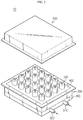
- FIGS. 2 and 3 are a perspective view and is a cross-sectioned view schematically showing a battery module according to an embodiment of the present disclosure
- FIG. 4 is a diagram for illustrating processes for manufacturing the battery module according to an embodiment of the present disclosure.
- a battery module 10 may include a plurality of can-type secondary batteries 100, a cooling tray 200 having an accommodation space capable of accommodating the plurality of can-type secondary batteries 100, a heatsink 300, and a thermally conductive adhesive solution 400 filled in the accommodation space of the cooling tray 200.
- the secondary battery employed at the battery module 10 according to the present disclosure may be a can-type secondary battery 100.
- the can-type secondary battery 100 is a secondary battery in which an electrode assembly is included in a metal can, and may be classified into a cylindrical battery and a rectangular battery depending on the shape of the metal can.
- the cylindrical secondary batteries are used, but the present disclosure is not limited thereto. That is, the cylindrical secondary battery of this embodiment may be replaced by a rectangular secondary battery.
- the secondary battery may include a cylindrical battery cell, a jelly-roll type electrode assembly accommodated in the battery cell, and a cap assembly coupled to an upper portion of the battery can.
- the cylindrical battery can may be made of a lightweight conductive metal material such as aluminum, stainless steel or an alloy thereof.
- the can-type secondary batteries 100 may be connected in series and/or in parallel depending on the output and capacity demanded for the battery module 10. Although not shown in the figures for convenience, the can-type secondary batteries 100 may be electrically connected to each other by a bus bar made of a copper plate.
- the cooling tray 200 may be a structure that gives an accommodation space for accommodating the can-type secondary batteries 100.
- the cooling tray 200 has a generally wide, flat and sealed bottom surface and may have a container shape so that a thermally conductive adhesive solution is filled to a preset height.
- the cooling tray 200 may be made of a metal material having excellent thermal conductivity to absorb the heat of the can-type secondary cylindrical batteries.
- An upper end of the cooling tray 200 may be bent to be horizontal with respect to the ground.
- the cooling tray 200 may be coupled to a tray cover 500 having a lower surface facing the bent upper surface thereof.
- the upper surface of the cooling tray 200 and the lower surface of the tray cover 500 may be adhered to each other by welding.
- the upper surface of the cooling tray 200 and the lower surface of the tray cover 500 may be bolted together after an O-ring is disposed therebetween.
- the can-type secondary batteries 100 may be protected from the outside since the inner side of the battery module is shielded by the coupling of the cooling tray 200 and the tray cover 500 as shown in FIG. 3 .
- the heatsink 300 is a component that indirectly cools the can-type secondary batteries 100 by absorbing the heat from the cooling tray 200 by means of thermal contact by allowing a coolant to pass through an inner flow path thereof, and may be disposed in contact with the bottom surface of the cooling tray 200.
- the coolant flowing in the flow path is not particularly limited as long as it may easily flow through the flow path and is excellent in cooling ability.
- the coolant may be water that may maximize cooling efficiency due to a high latent heat.
- the coolant may employ an antifreeze, a gas refrigerant, air, or the like, which may flow, without being limited to the above.
- the heatsink 300 may be made of aluminum or aluminum alloy having high thermal conductivity, without being limited thereto.
- the heatsink 300 may be made of copper, gold or silver.
- the heatsink 300 may be made of a ceramic material such as aluminum nitride and silicon carbide, other than metals.
- the heatsink 300 is a rectangular plate shape with a hollow structure and has a flow path therein. Also, an inlet 310 and an outlet 320 of the flow path may be provided at one side of the heatsink 300, respectively. The inlet 310 and the outlet 320 of the flow path may be connected to an inlet and an outlet of another heatsink, or to an external cooling water supply pipe and an external cooling water exhaust pipe.
- the plurality of can-type secondary batteries 100 are configured to be fixed only by the thermally conductive adhesive solution 400 without the use of a fixing structure or a separate fixing part in the cooling tray 200.
- the thermally conductive adhesive solution 400 is a material having thermal conductivity and adhesive property and may employ, for example, an epoxy resin, a silicone resin or the like.
- the thermally conductive adhesive solution 400 may be filled up to a height H of the accommodation space of the cooling tray 200.
- the can-type secondary batteries 100 may be fixedly positioned, and the contact area between the thermally conductive adhesive solution 400 and the can-type secondary batteries 100 may be maximized. Accordingly, the thermal conductivity between the cooling tray 200 and the can-type secondary batteries 100 may be significantly improved.
- the thermal contact resistance is large due to the difference in surface roughness between the empty space and the objects.
- the thermally conductive adhesive solution 400 fills the empty space, the can-type secondary batteries 100 may be naturally adhered and fixed in the thermally conductive adhesive solution 400 without using a separate fixing part.
- the thermal contact resistance caused by the difference in surface roughness between the cooling tray 200 and the can-type secondary batteries 100 is substantially not generated.
- the heat generated from the can-type secondary batteries 100 may be conducted to the cooling tray 200 more quickly and emitted to the heatsink 300.
- the cooling tray 200 of a container shape is prepared on a work place of a table (S 100).
- the thermally conductive adhesive solution 400 is injected into the cooling tray 200 to a preset height so that the accommodation space is partially filled with the thermally conductive adhesive solution 400 (S200).
- a plurality of can-type secondary batteries 100 are vertically immersed in the thermally conductive adhesive solution 400, respectively.
- a pick-up jig for the can-type secondary battery 100 may be used to immerse the can-type secondary batteries 100 at once in a bundle.
- the thermally conductive adhesive solution 400 is cured so that the can-type secondary batteries 100 are perfectly fixed at the corresponding locations (S300).
- the accommodation space accommodating the plurality of can-type secondary batteries 100 is sealed using the tray cover 500 coupled with the cooling tray 200 (S400).
- the cooling tray 200 is disposed at the upper surface of the heatsink 300.
- the preset height may mean the height of the surface of the thermally conductive adhesive solution 400 filled in the accommodation space of the cooling tray 200, when all of the can-type secondary batteries 100 are immersed in the thermally conductive adhesive solution 400.
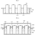
- FIG. 6 is a diagram corresponding to the portion (c) of FIG. 4 and depicts another embodiment of the present disclosure.
- the cooling tray 200 further includes a plurality of putting portions 210 into which the lower ends of the can-type secondary batteries 100 are partially fitted.
- the positions of the respective can-type secondary batteries 100 may not be aligned with each other. Also, until the thermally conductive adhesive solution 400 is fully cured, the can-type secondary batteries 100 are incompletely fixed and thus may be leaned just by a slight impact. However, if the cooling tray 200 having the plurality of placing portions 210 as shown in FIG. 6 is used, the problem of the former embodiment may be solved.
- the plurality of placing portions 210 of FIG. 6 are provided at predetermined locations on the bottom surface of the cooling tray 200, it is possible to guide the can-type secondary batteries 100 to be arranged properly.
- the can-type secondary batteries 100 may be easily arranged on the cooling tray 200.
- the plurality of the placing portions 210 may have, for example, a ring shape into which the lower ends of the can-type secondary batteries 100 may be partially fitted, thereby playing a role of holding the lower ends of the can-type secondary batteries 100.
- the can-type secondary batteries 100 may be disposed in the corresponding placing portions 210 one by one, thereby reducing the assembling tolerance of the can-type secondary batteries 100.
- FIG. 7 is a cross-sectioned view schematically showing a battery module 10 according to still another embodiment of the present disclosure
- FIG. 8 is an enlarged view showing main parts of FIG. 7 .
- FIGS. 7 and 8 a battery module 10 according to another embodiment of the present disclosure will be described with reference to FIGS. 7 and 8 .
- the same reference numerals as those in the former embodiment denote the same components and will not be described in detail here.
- the battery module 10 includes a tray cover 500 coupled to the cooling tray 200 to seal the accommodation space.
- the tray cover 500 may include a plurality of cooling sockets 510 and a connection portion 520 connecting the plurality of cooling sockets 510.
- the cooling socket 510 has a pipe shape capable of covering the outer circumference of the can-type secondary battery 100 and is formed to surround the upper end of the can-type secondary battery 100 exposed above the surface of the thermally conductive adhesive solution 400. As shown in FIG. 7 , the cooling sockets 510 may be connected to each other by the connection portion 520. In addition, both ends of the connection portion 520 may be connected to side surfaces 530a, 530b of the tray cover. In other words, the cooling sockets 510 may be fixedly coupled to the side surfaces 530a, 530b of the tray cover by the connection portion 520.
- the can-type secondary batteries 100 may be inserted into and held by the corresponding cooling sockets 510, respectively.
- the can-type secondary batteries 100 may be fixed additionally, thereby improving the stability of the can-type secondary batteries 100.
- the upper portion of the can-type secondary battery 100 at which electrode terminals are located generate heat more greatly, compared to other portions.
- the upper portion of the can-type secondary battery 100 is not in contact state with the thermally conductive adhesive solution 400, which may cause a greater temperature difference between the upper portion of the can-type secondary battery 100 and the portion immersed in the thermally conductive adhesive solution 400.
- the upper portion of the can-type secondary battery 100 may be cooled separately.
- the plurality of cooling sockets 510, the connection portion 520 and the side surfaces 530a, 530b of the tray cover may communicate with each other in a hollow structure so that a flow path is provided therein.
- the flow path is formed in a lower region 530a of the tray cover 500 based on the intersection point where the side surfaces 530a, 530b of the tray cover meet the connection portion 520, and the flow path does not need to be formed in an upper region 530b.
- the coolant may be introduced at a left end of the tray cover 500, pass through the connection portion 520 and each cooling socket 510, and be discharged at a right end of the tray cover 500.
- a coolant flows in the cooling socket 510, and the cooling socket 510 surrounds a periphery of the upper end of the can-type secondary battery 100.
- the tray cover 500 may be coupled to the cooling tray 200 to protect the can-type secondary batteries 100 from the outside and additionally further improve the fixation and cooling performance for the can-type secondary batteries 100.
- a battery pack according to the present disclosure may include at least one battery modules of the present disclosure.
- the battery pack according to the present disclosure may further include a pack case for accommodating the battery module, and various devices for controlling charge and discharge of the battery module such as a battery management system (BMS), a current sensor, a fuse or the like.
- BMS battery management system
- the battery module according to the present disclosure may be applied to a vehicle such as an electric vehicle or a hybrid electric vehicle, or a power storage system (ESS).
- a vehicle such as an electric vehicle or a hybrid electric vehicle, or a power storage system (ESS).
- ESS power storage system
Landscapes
- Chemical & Material Sciences (AREA)
- Chemical Kinetics & Catalysis (AREA)
- Electrochemistry (AREA)
- General Chemical & Material Sciences (AREA)
- Engineering & Computer Science (AREA)
- Manufacturing & Machinery (AREA)
- Secondary Cells (AREA)
- Battery Mounting, Suspending (AREA)
Abstract
Description
- The present disclosure relates to a battery module, and more particularly, to a battery module to which a new assembling structure is applied to satisfy the cooling efficiency and the simplified assembling structure for secondary batteries simultaneously, and a method for manufacturing the battery module.
- The present application claims priority to Korean Patent Application No.
10-2017-0141468 filed on October 27, 2017 - A secondary battery cell includes positive and negative electrode current collectors, a separator, active materials and an electrolyte, and may be repeatedly charged and discharged by electrochemical reactions between components. Since the battery cells are densely provided in a compact space of a battery module, it is important to easily release the heat generated by each battery cell. Since the battery cell is charged and discharged due to an electrochemical reaction, if the heat of the battery module generated during the charging and discharging process is not effectively removed, heat accumulation occurs, which may promote the degradation of the battery module, and in more severe cases, cause ignition or explosion.
- Thus, a high-output large-capacity battery module and a battery pack having the battery module are required to have a cooling device for cooling battery cells included therein.
-
FIG. 1 is a diagram schematically showing a cooling structure of a conventional battery module. As shown inFIG. 1 , the conventional battery module may include, for example,secondary battery cells 1, ahousing 2 for accommodating and holding thesecondary battery cells 1, aheatsink 3, and a thermal interface material (TIM) 4. - Since the
secondary battery cells 1 should be electrically connected to each other, it is necessary to fix thesecondary battery cells 1 securely. To this end, thehousing 2 typically has a fixing structure capable of holding the plurality ofsecondary battery cells 1 individually. For example, as shown inFIG. 1 , a cylindrical secondary battery may be inserted to constrain thesecondary battery cells 1. Alternatively, a separate fixing frame may be used so that the fixing frame is assembled to thehousing 2 in a state of holding the plurality ofsecondary battery cells 1 integrally. Thehousing 2 may be made of aluminum or aluminum alloy with excellent mechanical rigidity and heat dissipation performance. - The
heatsink 3 is a cooling device for suitably keeping the temperature of secondary battery cells during charging and discharging and may be disposed in contact with a lower portion of thehousing 2. Here, theheatsink 3 may be configured so that a coolant flows therein, and may absorb heat from thesecondary battery cells 1 through thehousing 2. - The TIM 4 is disposed at an interface between the
housing 2 and theheatsink 3 to reduce contact resistance between thehousing 2 and theheatsink 3. The TIM 4 may employ a thermally conductive pad or resin. - However, in the cooling configuration of the conventional battery module, even though the TIM 4 is used, the cooling efficiency is inevitably lowered due to the resistance elements present on the heat conduction path. In addition, since a fixing structure needs to be added to the
housing 2 or a separate component needs to be used in order to fix thesecondary battery cells 1, it is difficult to design a secondary battery assembling structure at thehousing 2, and the energy density is lowered. - The present disclosure is designed to solve the problems of the related art, and therefore the present disclosure is directed to providing a battery module, which has a new cooling and assembling structure capable of satisfying the cooling efficiency and the simplified assembling structure for secondary batteries simultaneously, and a method for manufacturing the battery module.
- However, the objects of the present disclosure are not limited to the above, and objects not mentioned herein may be clearly understood from the present specification and the accompanying drawings by those skilled in the art.
- In one aspect of the present disclosure, there is provided a battery module, comprising: a plurality of can-type secondary batteries; a cooling tray formed in a container shape and having an accommodation space capable of accommodating the plurality of can-type secondary batteries; a heatsink having a hollow structure in which a coolant flows, the heatsink being disposed in contact with an outer surface of the cooling tray; and a thermally conductive adhesive solution filled in the accommodation space of the cooling tray, wherein the plurality of can-type secondary batteries are disposed to stand up so that a lower portion thereof is immersed in the thermally conductive adhesive solution.
- The thermally conductive adhesive solution may be filled to a height of the accommodation space of the cooling tray.
- The cooling tray may have a plurality of placing portions into which lower ends of the can-type secondary batteries are partially fitted.
- The battery module may further comprise a tray cover coupled to the cooling tray to seal the accommodation space, and the tray cover may include a plurality of cooling sockets having a pipe shape and provided to cover outer circumferences of the can-type secondary batteries, which are exposed above a surface of the thermally conductive adhesive solution.
- The tray cover may further include a connection portion provided to connect the plurality of cooling sockets and a side surface of the tray cover.
- The plurality of cooling sockets, the connection portion and the side surface of the tray cover may be provided in a hollow structure to communicate with each other so that a flow path is formed therein.
- The can-type secondary battery may be a rectangular or cylindrical secondary battery.
- In another aspect of the present disclosure, there is also provided a battery pack, comprising the battery module described above.
- In another aspect of the present disclosure, there is also provided a method for manufacturing a battery module, comprising: a preparation step of preparing a cooling tray having a container shape; an injection step of injecting a thermally conductive adhesive solution into the cooling tray to a preset height; and a disposition step of fixing a plurality of can-type secondary batteries to be vertically immersed in the thermally conductive adhesive solution before the thermally conductive adhesive solution is cured.
- The cooling tray may have a plurality of placing portions into which lower ends of the can-type secondary batteries are partially fitted, and in the disposition step, the can-type secondary batteries may be disposed to correspond to the placing portions one by one.
- The method may further comprise a tray cover coupling step of sealing an accommodation space of the cooling tray, which accommodates the plurality of can-type secondary batteries, by using a tray cover coupled to the cooling tray.
- The tray cover may include a plurality of cooling sockets having a pipe shape and provided to cover outer circumferences of the can-type secondary batteries, which are exposed above a surface of the thermally conductive adhesive solution, and a connection portion provided to connect the plurality of cooling sockets and a side surface of the tray cover, and in the tray cover coupling step, the can-type secondary batteries may be inserted into and held by the cooling sockets one by one.
- According to an embodiment of the present disclosure, it is possible to provide a battery module, which has a new cooling and assembling structure capable of satisfying the cooling efficiency and the simplified assembling structure simultaneously.
- Specifically, since the can-type secondary batteries are fixed using a thermally conductive adhesive solution, a separate fixing structure may not be used. In addition, since the contact area between the thermally conductive adhesive solution and the can-type secondary batteries is sufficiently secured, the cooling efficiency may be improved.
- According to another embodiment of the present disclosure, since a tray cover coupled to the cooling tray to protect the can-type secondary batteries from the outside and to additionally fix and cool the can-type secondary batteries is provided, the can-type secondary batteries may be fixed and cooled more efficiently.
- The effects of the present disclosure are not limited to the above, and effects not mentioned herein may be clearly understood from the present specification and the accompanying drawings by those skilled in the art.
-
-
FIG. 1 is a diagram schematically showing a cooling structure of a conventional battery module. -
FIG. 2 is a perspective view schematically showing a battery module according to an embodiment of the present disclosure. -
FIG. 3 is a cross-sectioned view schematically showing the battery module according to an embodiment of the present disclosure. -
FIG. 4 is a diagram for illustrating processes for manufacturing the battery module according to an embodiment of the present disclosure. -
FIG. 5 is a flowchart for illustrating a method for manufacturing the battery module according to an embodiment of the present disclosure. -
FIG. 6 is a cross-sectioned view for illustrating a battery module according to another embodiment of the present disclosure. -
FIG. 7 is a cross-sectioned view schematically showing a battery module according to still another embodiment of the present disclosure. -
FIG. 8 is an enlarged view showing main parts ofFIG. 7 . - Hereinafter, preferred embodiments of the present disclosure will be described in detail with reference to the accompanying drawings. Prior to the description, it should be understood that the terms used in the specification and the appended claims should not be construed as limited to general and dictionary meanings, but interpreted based on the meanings and concepts corresponding to technical aspects of the present disclosure on the basis of the principle that the inventor is allowed to define terms appropriately for the best explanation.
- Therefore, the description proposed herein is just a preferable example for the purpose of illustrations only, not intended to limit the scope of the disclosure, so it should be understood that other equivalents and modifications could be made thereto without departing from the scope of the disclosure.
- The embodiments disclosed herein are provided for more perfect explanation of the present disclosure, and thus the shape, size and the like of components may be exaggerated, omitted or simplified in the drawings for better understanding. Thus, the size and ratio of components in the drawings do not wholly reflect the actual size and ratio.
-
FIGS. 2 and3 are a perspective view and is a cross-sectioned view schematically showing a battery module according to an embodiment of the present disclosure, andFIG. 4 is a diagram for illustrating processes for manufacturing the battery module according to an embodiment of the present disclosure. - Referring to the figures, a
battery module 10 according to an embodiment of the present disclosure may include a plurality of can-typesecondary batteries 100, acooling tray 200 having an accommodation space capable of accommodating the plurality of can-typesecondary batteries 100, aheatsink 300, and a thermally conductiveadhesive solution 400 filled in the accommodation space of thecooling tray 200. - First, the secondary battery employed at the
battery module 10 according to the present disclosure may be a can-typesecondary battery 100. Here, the can-typesecondary battery 100 is a secondary battery in which an electrode assembly is included in a metal can, and may be classified into a cylindrical battery and a rectangular battery depending on the shape of the metal can. In this embodiment, the cylindrical secondary batteries are used, but the present disclosure is not limited thereto. That is, the cylindrical secondary battery of this embodiment may be replaced by a rectangular secondary battery. - Although not shown in detail in the figures, the secondary battery may include a cylindrical battery cell, a jelly-roll type electrode assembly accommodated in the battery cell, and a cap assembly coupled to an upper portion of the battery can. Here, the cylindrical battery can may be made of a lightweight conductive metal material such as aluminum, stainless steel or an alloy thereof.
- The can-type
secondary batteries 100 may be connected in series and/or in parallel depending on the output and capacity demanded for thebattery module 10. Although not shown in the figures for convenience, the can-typesecondary batteries 100 may be electrically connected to each other by a bus bar made of a copper plate. - The cooling
tray 200 may be a structure that gives an accommodation space for accommodating the can-typesecondary batteries 100. - As shown in
FIGS. 2 to 4 , the coolingtray 200 has a generally wide, flat and sealed bottom surface and may have a container shape so that a thermally conductive adhesive solution is filled to a preset height. In addition, the coolingtray 200 may be made of a metal material having excellent thermal conductivity to absorb the heat of the can-type secondary cylindrical batteries. - An upper end of the cooling
tray 200 may be bent to be horizontal with respect to the ground. The coolingtray 200 may be coupled to atray cover 500 having a lower surface facing the bent upper surface thereof. At this time, the upper surface of the coolingtray 200 and the lower surface of thetray cover 500 may be adhered to each other by welding. Alternatively, the upper surface of the coolingtray 200 and the lower surface of thetray cover 500 may be bolted together after an O-ring is disposed therebetween. The can-typesecondary batteries 100 may be protected from the outside since the inner side of the battery module is shielded by the coupling of the coolingtray 200 and thetray cover 500 as shown inFIG. 3 . - The
heatsink 300 is a component that indirectly cools the can-typesecondary batteries 100 by absorbing the heat from the coolingtray 200 by means of thermal contact by allowing a coolant to pass through an inner flow path thereof, and may be disposed in contact with the bottom surface of the coolingtray 200. - The coolant flowing in the flow path is not particularly limited as long as it may easily flow through the flow path and is excellent in cooling ability. For example, the coolant may be water that may maximize cooling efficiency due to a high latent heat. However, the coolant may employ an antifreeze, a gas refrigerant, air, or the like, which may flow, without being limited to the above.
- The
heatsink 300 may be made of aluminum or aluminum alloy having high thermal conductivity, without being limited thereto. For example, theheatsink 300 may be made of copper, gold or silver. In addition, theheatsink 300 may be made of a ceramic material such as aluminum nitride and silicon carbide, other than metals. - In this embodiment, the
heatsink 300 is a rectangular plate shape with a hollow structure and has a flow path therein. Also, aninlet 310 and anoutlet 320 of the flow path may be provided at one side of theheatsink 300, respectively. Theinlet 310 and theoutlet 320 of the flow path may be connected to an inlet and an outlet of another heatsink, or to an external cooling water supply pipe and an external cooling water exhaust pipe. - Meanwhile, in the present disclosure, the plurality of can-type
secondary batteries 100 are configured to be fixed only by the thermally conductiveadhesive solution 400 without the use of a fixing structure or a separate fixing part in thecooling tray 200. The thermally conductiveadhesive solution 400 is a material having thermal conductivity and adhesive property and may employ, for example, an epoxy resin, a silicone resin or the like. - The thermally conductive
adhesive solution 400 may be filled up to a height H of the accommodation space of the coolingtray 200. In this case, in thecooling tray 200, the can-typesecondary batteries 100 may be fixedly positioned, and the contact area between the thermally conductiveadhesive solution 400 and the can-typesecondary batteries 100 may be maximized. Accordingly, the thermal conductivity between the coolingtray 200 and the can-typesecondary batteries 100 may be significantly improved. - In other words, if the can-type
secondary battery 100 is placed in contact with the coolingtray 200 using a separate fixing part in thecooling tray 200, the thermal contact resistance is large due to the difference in surface roughness between the empty space and the objects. However, in the present disclosure, since the thermally conductiveadhesive solution 400 fills the empty space, the can-typesecondary batteries 100 may be naturally adhered and fixed in the thermally conductiveadhesive solution 400 without using a separate fixing part. In addition, the thermal contact resistance caused by the difference in surface roughness between the coolingtray 200 and the can-typesecondary batteries 100 is substantially not generated. Thus, the heat generated from the can-typesecondary batteries 100 may be conducted to thecooling tray 200 more quickly and emitted to theheatsink 300. - Next, a process for manufacturing process the
battery module 10 will be briefly described with reference toFIGS. 4 and5 . - First, as in the portion (a) of
FIG. 4 , the coolingtray 200 of a container shape is prepared on a work place of a table (S 100). - After that, as in the portion (b) of
FIG. 4 , the thermally conductiveadhesive solution 400 is injected into the coolingtray 200 to a preset height so that the accommodation space is partially filled with the thermally conductive adhesive solution 400 (S200). After that, as shown in the portion (c) ofFIG. 4 , before the thermally conductiveadhesive solution 400 is cured, a plurality of can-typesecondary batteries 100 are vertically immersed in the thermally conductiveadhesive solution 400, respectively. At this time, a pick-up jig for the can-typesecondary battery 100 may be used to immerse the can-typesecondary batteries 100 at once in a bundle. After a predetermined time, the thermally conductiveadhesive solution 400 is cured so that the can-typesecondary batteries 100 are perfectly fixed at the corresponding locations (S300). - After that, though not shown in
FIG. 4 , as shown inFIG. 3 , the accommodation space accommodating the plurality of can-typesecondary batteries 100 is sealed using thetray cover 500 coupled with the cooling tray 200 (S400). In addition, the coolingtray 200 is disposed at the upper surface of theheatsink 300. - For reference, in the portion (b) of
FIG. 4 , the preset height may mean the height of the surface of the thermally conductiveadhesive solution 400 filled in the accommodation space of the coolingtray 200, when all of the can-typesecondary batteries 100 are immersed in the thermally conductiveadhesive solution 400. - Meanwhile,
FIG. 6 is a diagram corresponding to the portion (c) ofFIG. 4 and depicts another embodiment of the present disclosure. In the embodiment ofFIG. 6 , the coolingtray 200 further includes a plurality of puttingportions 210 into which the lower ends of the can-typesecondary batteries 100 are partially fitted. - In the former embodiment, when the can-type
secondary batteries 100 are disposed on thecooling tray 200, since there is no alignment criterion, the positions of the respective can-typesecondary batteries 100 may not be aligned with each other. Also, until the thermally conductiveadhesive solution 400 is fully cured, the can-typesecondary batteries 100 are incompletely fixed and thus may be leaned just by a slight impact. However, if the coolingtray 200 having the plurality of placingportions 210 as shown inFIG. 6 is used, the problem of the former embodiment may be solved. - That is, since the plurality of placing
portions 210 ofFIG. 6 are provided at predetermined locations on the bottom surface of the coolingtray 200, it is possible to guide the can-typesecondary batteries 100 to be arranged properly. Thus, the can-typesecondary batteries 100 may be easily arranged on thecooling tray 200. In addition, the plurality of the placingportions 210 may have, for example, a ring shape into which the lower ends of the can-typesecondary batteries 100 may be partially fitted, thereby playing a role of holding the lower ends of the can-typesecondary batteries 100. Thus, when the plurality of can-typesecondary batteries 100 are fixed in the thermally conductiveadhesive solution 400, the can-typesecondary batteries 100 may be disposed in the corresponding placingportions 210 one by one, thereby reducing the assembling tolerance of the can-typesecondary batteries 100. -
FIG. 7 is a cross-sectioned view schematically showing abattery module 10 according to still another embodiment of the present disclosure, andFIG. 8 is an enlarged view showing main parts ofFIG. 7 . - Next, a
battery module 10 according to another embodiment of the present disclosure will be described with reference toFIGS. 7 and8 . The same reference numerals as those in the former embodiment denote the same components and will not be described in detail here. - Referring to the figures, the
battery module 10 according to still another embodiment of the present disclosure includes atray cover 500 coupled to thecooling tray 200 to seal the accommodation space. Thetray cover 500 may include a plurality of coolingsockets 510 and aconnection portion 520 connecting the plurality of coolingsockets 510. - The cooling
socket 510 has a pipe shape capable of covering the outer circumference of the can-typesecondary battery 100 and is formed to surround the upper end of the can-typesecondary battery 100 exposed above the surface of the thermally conductiveadhesive solution 400. As shown inFIG. 7 , the coolingsockets 510 may be connected to each other by theconnection portion 520. In addition, both ends of theconnection portion 520 may be connected toside surfaces sockets 510 may be fixedly coupled to theside surfaces connection portion 520. Thus, if the upper portion of the coolingtray 200 is covered with thetray cover 500, the can-typesecondary batteries 100 may be inserted into and held by the corresponding coolingsockets 510, respectively. In this case, the can-typesecondary batteries 100 may be fixed additionally, thereby improving the stability of the can-typesecondary batteries 100. - Meanwhile, the upper portion of the can-type
secondary battery 100 at which electrode terminals are located generate heat more greatly, compared to other portions. However, in the former embodiments, the upper portion of the can-typesecondary battery 100 is not in contact state with the thermally conductiveadhesive solution 400, which may cause a greater temperature difference between the upper portion of the can-typesecondary battery 100 and the portion immersed in the thermally conductiveadhesive solution 400. In order to solve this problem, in this embodiment, the upper portion of the can-typesecondary battery 100 may be cooled separately. - Specifically, in the
tray cover 500 of this embodiment, the plurality of coolingsockets 510, theconnection portion 520 and theside surfaces FIG. 7 , the flow path is formed in alower region 530a of thetray cover 500 based on the intersection point where theside surfaces connection portion 520, and the flow path does not need to be formed in anupper region 530b. - For example, the coolant may be introduced at a left end of the
tray cover 500, pass through theconnection portion 520 and each coolingsocket 510, and be discharged at a right end of thetray cover 500. At this time, as shown inFIG. 8 , a coolant flows in thecooling socket 510, and thecooling socket 510 surrounds a periphery of the upper end of the can-typesecondary battery 100. Thus, it is possible to effectively cool the upper portion of the can-typesecondary battery 100, which generate heat greatly. - If the
tray cover 500 configured as above is used, thetray cover 500 may be coupled to thecooling tray 200 to protect the can-typesecondary batteries 100 from the outside and additionally further improve the fixation and cooling performance for the can-typesecondary batteries 100. - Meanwhile, a battery pack according to the present disclosure may include at least one battery modules of the present disclosure. In addition to the battery module, the battery pack according to the present disclosure may further include a pack case for accommodating the battery module, and various devices for controlling charge and discharge of the battery module such as a battery management system (BMS), a current sensor, a fuse or the like.
- The battery module according to the present disclosure may be applied to a vehicle such as an electric vehicle or a hybrid electric vehicle, or a power storage system (ESS).
- The present disclosure has been described in detail. However, it should be understood that the detailed description and specific examples, while indicating preferred embodiments of the disclosure, are given by way of illustration only, since various changes and modifications within the scope of the disclosure will become apparent to those skilled in the art from this detailed description.
- Meanwhile, when the terms indicating up, down, left, right, front and rear directions are used in the specification, it is obvious to those skilled in the art that these merely represent relative locations for convenience in explanation and may vary based on a location of an observer or an object to be observed.
Claims (12)
- A battery module, comprising:a plurality of can-type secondary batteries;a cooling tray formed in a container shape and having an accommodation space capable of accommodating the plurality of can-type secondary batteries;a heatsink having a hollow structure in which a coolant flows, the heatsink being disposed in contact with an outer surface of the cooling tray; anda thermally conductive adhesive solution filled in the accommodation space of the cooling tray,wherein the plurality of can-type secondary batteries are disposed to stand up so that a lower portion thereof is immersed in the thermally conductive adhesive solution.
- The battery module according to claim 1,
wherein the thermally conductive adhesive solution is filled to a height of the accommodation space of the cooling tray. - The battery module according to claim 1,
wherein the cooling tray has a plurality of placing portions into which lower ends of the can-type secondary batteries are partially fitted. - The battery module according to claim 1, further comprising:a tray cover coupled to the cooling tray to seal the accommodation space,wherein the tray cover includes a plurality of cooling sockets having a pipe shape and provided to cover outer circumferences of the can-type secondary batteries, which are exposed above a surface of the thermally conductive adhesive solution.
- The battery module according to claim 4,
wherein the tray cover further includes a connection portion provided to connect the plurality of cooling sockets and a side surface of the tray cover. - The battery module according to claim 5,
wherein the plurality of cooling sockets, the connection portion and the side surface of the tray cover are provided in a hollow structure to communicate with each other so that a flow path is formed therein. - The battery module according to claim 1,
wherein the can-type secondary battery is a rectangular or cylindrical secondary battery. - A battery pack, comprising the battery module according to any one of claims 1 to 7.
- A method for manufacturing a battery module, comprising:a preparation step of preparing a cooling tray having a container shape;an injection step of injecting a thermally conductive adhesive solution into the cooling tray to a preset height; anda disposition step of fixing a plurality of can-type secondary batteries to be vertically immersed in the thermally conductive adhesive solution before the thermally conductive adhesive solution is cured.
- The method for manufacturing a battery module according to claim 9,
wherein the cooling tray has a plurality of placing portions into which lower ends of the can-type secondary batteries are partially fitted, and
wherein in the disposition step, the can-type secondary batteries are disposed to correspond to the placing portions one by one. - The method for manufacturing a battery module according to claim 9, further comprising:
a tray cover coupling step of sealing an accommodation space of the cooling tray, which accommodates the plurality of can-type secondary batteries, by using a tray cover coupled to the cooling tray. - The method for manufacturing a battery module according to claim 11,
wherein the tray cover includes a plurality of cooling sockets having a pipe shape and provided to cover outer circumferences of the can-type secondary batteries, which are exposed above a surface of the thermally conductive adhesive solution, and a connection portion provided to connect the plurality of cooling sockets and a side surface of the tray cover, and
wherein in the tray cover coupling step, the can-type secondary batteries are inserted into and held by the cooling sockets one by one.
Priority Applications (1)
| Application Number | Priority Date | Filing Date | Title |
|---|---|---|---|
| PL18871412T PL3644434T3 (en) | 2017-10-27 | 2018-09-27 | Battery module in which cooling and assembly structure is simplified, and manufacturing method therefor |
Applications Claiming Priority (2)
| Application Number | Priority Date | Filing Date | Title |
|---|---|---|---|
| KR1020170141468A KR102258178B1 (en) | 2017-10-27 | 2017-10-27 | Battery module simplified cooling and assembling structure and Method for manufacturing the same |
| PCT/KR2018/011405 WO2019083176A1 (en) | 2017-10-27 | 2018-09-27 | Battery module in which cooling and assembly structure is simplified, and manufacturing method therefor |
Publications (3)
| Publication Number | Publication Date |
|---|---|
| EP3644434A1 true EP3644434A1 (en) | 2020-04-29 |
| EP3644434A4 EP3644434A4 (en) | 2020-08-05 |
| EP3644434B1 EP3644434B1 (en) | 2021-11-03 |
Family
ID=66247518
Family Applications (1)
| Application Number | Title | Priority Date | Filing Date |
|---|---|---|---|
| EP18871412.5A Active EP3644434B1 (en) | 2017-10-27 | 2018-09-27 | Battery module in which cooling and assembly structure is simplified, and manufacturing method therefor |
Country Status (7)
| Country | Link |
|---|---|
| US (1) | US11342604B2 (en) |
| EP (1) | EP3644434B1 (en) |
| JP (1) | JP7047215B2 (en) |
| KR (1) | KR102258178B1 (en) |
| CN (1) | CN110692162B (en) |
| PL (1) | PL3644434T3 (en) |
| WO (1) | WO2019083176A1 (en) |
Families Citing this family (37)
| Publication number | Priority date | Publication date | Assignee | Title |
|---|---|---|---|---|
| KR102941674B1 (en) * | 2020-05-29 | 2026-03-20 | 주식회사 엘지에너지솔루션 | Heat sink |
| KR102729323B1 (en) | 2020-06-05 | 2024-11-11 | 삼성에스디아이 주식회사 | Rechargeable battery pack |
| KR102937900B1 (en) | 2020-06-10 | 2026-03-11 | 주식회사 엘지에너지솔루션 | Battery module and menufacturing method for the same |
| CN114830419B (en) * | 2020-06-16 | 2025-01-28 | 株式会社Lg新能源 | Battery pack, electronic device including the battery pack, and vehicle |
| WO2021256878A1 (en) * | 2020-06-17 | 2021-12-23 | 주식회사 엘지에너지솔루션 | Battery module, battery pack comprising same, vehicle, and method for manufacturing battery pack |
| JP7419533B2 (en) | 2020-07-10 | 2024-01-22 | 寧徳時代新能源科技股▲分▼有限公司 | Batteries, related equipment, manufacturing methods, and manufacturing equipment |
| CA3156564A1 (en) | 2020-07-10 | 2022-01-13 | Contemporary Amperex Technology Co., Limited | Case of battery, battery, power consumption device, and method and device for preparing battery |
| PL3965216T3 (en) * | 2020-07-10 | 2023-06-19 | Contemporary Amperex Technology Co., Limited | BATTERY AND RELATED INSTRUMENTS, PREPARATION METHOD AND PREPARATION DEVICE |
| EP4184636A3 (en) | 2020-07-10 | 2023-09-20 | Contemporary Amperex Technology Co., Limited | Battery and power consumption device |
| KR102768760B1 (en) | 2020-07-10 | 2025-02-19 | 컨템포러리 엠퍼렉스 테크놀로지 (홍콩) 리미티드 | Battery, electric device, method for manufacturing battery and device |
| KR102947182B1 (en) | 2020-07-28 | 2026-04-02 | 주식회사 엘지에너지솔루션 | Heat sink assembly and manufacturing method thereof for battery pack |
| KR102943036B1 (en) * | 2020-07-30 | 2026-03-24 | 주식회사 엘지에너지솔루션 | Battery module and method for manufacturing the same |
| KR102943040B1 (en) * | 2020-10-22 | 2026-03-24 | 주식회사 엘지에너지솔루션 | Battery pack and manufacturing method thereof |
| CN112216861A (en) * | 2020-11-05 | 2021-01-12 | 厦门致力金刚石科技股份有限公司 | Lithium battery monomer, lithium battery pack and plate structure |
| KR102755674B1 (en) * | 2020-11-16 | 2025-01-20 | 주식회사 엘지에너지솔루션 | Apparatus for cooling of battery cell, battery pack having the same, and method for cooling of battery cell using the same |
| EP4657612A3 (en) * | 2021-01-11 | 2026-03-18 | LG Energy Solution, Ltd. | Battery pack and vehicle comprising same |
| ES3057109T3 (en) | 2021-01-11 | 2026-02-26 | Lg Energy Solution Ltd | Battery pack and vehicle including same |
| KR102952238B1 (en) * | 2021-01-11 | 2026-04-13 | 주식회사 엘지에너지솔루션 | Battery pack, appatatus and method for manufacturing the battery pack |
| JP7640585B2 (en) * | 2021-02-22 | 2025-03-05 | エルジー エナジー ソリューション リミテッド | Battery pack and automobile including same |
| KR102648405B1 (en) * | 2021-06-18 | 2024-03-18 | 니구옌딘흉 | Battery pack using immersion cooling method |
| FR3125635B1 (en) * | 2021-07-20 | 2024-02-09 | Psa Automobiles Sa | ELECTRIC STORAGE DEVICE WITH PARTIALLY IMMERSED CELLS |
| CN113809432B (en) * | 2021-09-10 | 2025-05-30 | 哲弗智能系统(上海)有限公司 | Battery Thermal Management System |
| EP4441835A4 (en) * | 2021-11-29 | 2025-10-01 | Laserax Inc | BATTERY ASSEMBLY AND METHOD FOR MOUNTING A BATTERY ASSEMBLY |
| ES3067846T3 (en) * | 2021-12-20 | 2026-05-26 | Lg Energy Solution Ltd | Battery module, and battery pack and vehicle including same |
| CN116964842A (en) * | 2021-12-24 | 2023-10-27 | 宁德时代新能源科技股份有限公司 | Battery, electrical device, battery preparation method and manufacturing mold |
| KR102964089B1 (en) * | 2022-01-04 | 2026-05-12 | 주식회사 엘지에너지솔루션 | Battery module and method thereof |
| DE102022004502A1 (en) * | 2022-12-01 | 2024-06-06 | Mercedes-Benz Group AG | Battery cell arrangement for an electrical energy storage device of an at least partially electrically operated motor vehicle, method for producing a battery cell arrangement and method for dismantling a battery cell arrangement |
| CN115621650B (en) * | 2022-12-02 | 2023-03-14 | 北京艺玺科技有限公司 | Solid-state battery module safety protection structure |
| US20240286753A1 (en) * | 2023-02-23 | 2024-08-29 | Rolls-Royce Deutschland Ltd & Co Kg | Thermal management system for a battery |
| US20240313304A1 (en) * | 2023-03-14 | 2024-09-19 | Deere & Company | Energy storage device having cell with coating |
| CN120883422A (en) * | 2023-03-21 | 2025-10-31 | Sabic环球技术有限责任公司 | Battery pack with battery modules partially immersed in coolant |
| KR102887874B1 (en) * | 2023-12-11 | 2025-11-19 | 주식회사 엘지에너지솔루션 | Cooling device and battery cell stack comprising the same |
| CN117638347B (en) * | 2023-12-15 | 2024-11-05 | 欣旺达动力科技股份有限公司 | Battery pack and electric equipment |
| WO2026050203A1 (en) * | 2024-08-27 | 2026-03-05 | Re:Build Manufacturing, LLC | Modular battery pack assembly |
| KR20260063384A (en) * | 2024-10-30 | 2026-05-07 | 에스케이이노베이션 주식회사 | Immersion cooling module and the control method using the same |
| CN122178052A (en) * | 2024-12-06 | 2026-06-09 | 小米汽车科技有限公司 | Battery packs and their assembly methods, electrical equipment |
| WO2026163580A1 (en) * | 2025-01-31 | 2026-08-06 | パナソニックエナジー株式会社 | Power storage module |
Family Cites Families (23)
| Publication number | Priority date | Publication date | Assignee | Title |
|---|---|---|---|---|
| JP4514344B2 (en) * | 2001-02-07 | 2010-07-28 | 電気化学工業株式会社 | Thermally conductive resin molding and its use |
| KR100637469B1 (en) * | 2004-11-30 | 2006-10-23 | 삼성에스디아이 주식회사 | Secondary battery module |
| US20070218353A1 (en) * | 2005-05-12 | 2007-09-20 | Straubel Jeffrey B | System and method for inhibiting the propagation of an exothermic event |
| KR101067627B1 (en) | 2006-11-13 | 2011-09-26 | 주식회사 엘지화학 | Battery module with compact structure and excellent heat dissipation |
| DE102007010745B4 (en) | 2007-02-27 | 2009-01-22 | Daimler Ag | Battery with a heat conducting plate |
| FR2924857B1 (en) * | 2007-12-06 | 2014-06-06 | Valeo Equip Electr Moteur | ELECTRICAL SUPPLY DEVICE COMPRISING A RECEPTION UNIT FOR ULTRA CAPACITY STORAGE UNITS |
| WO2011007534A1 (en) | 2009-07-17 | 2011-01-20 | パナソニック株式会社 | Battery module and battery pack using the same |
| US9905821B2 (en) * | 2010-11-15 | 2018-02-27 | Volkswagen Ag | Vehicle battery packaging |
| CN103563124B (en) | 2011-05-30 | 2016-08-17 | 松下知识产权经营株式会社 | Battery block and manufacture method thereof |
| JP5984009B2 (en) | 2012-09-27 | 2016-09-06 | パナソニックIpマネジメント株式会社 | Battery pack and power supply device including the same |
| KR102065748B1 (en) | 2013-01-07 | 2020-01-14 | 에스케이이노베이션 주식회사 | Thermal pad for secondary battery and Battery module having the same |
| CN103811831B (en) * | 2013-11-18 | 2016-03-16 | 吉林大学 | A kind of lithium-ion-power cell liquid cooling structure |
| KR101773105B1 (en) * | 2014-07-31 | 2017-08-30 | 주식회사 엘지화학 | Battery module |
| JP6102896B2 (en) | 2014-11-26 | 2017-03-29 | トヨタ自動車株式会社 | Assembled battery |
| US9620830B2 (en) * | 2014-12-16 | 2017-04-11 | Xinen Technology Hong Kong Company, Ltd. | Vehicle battery module with cooling and safety features |
| KR101865995B1 (en) | 2015-03-27 | 2018-06-08 | 주식회사 엘지화학 | Battery module |
| DE102015118605B4 (en) * | 2015-10-30 | 2025-05-22 | Dr. Ing. H.C. F. Porsche Aktiengesellschaft | Energy storage device for a vehicle and method for producing an energy storage device |
| US10116018B2 (en) * | 2016-01-07 | 2018-10-30 | GM Global Technology Operations LLC | Cure in place thermal interface material |
| KR102067713B1 (en) | 2016-05-31 | 2020-01-17 | 주식회사 엘지화학 | Battery module, battery pack comprising the battery module and vehicle comprising the battery pack |
| KR102634776B1 (en) | 2016-06-15 | 2024-02-08 | 에스케이하이닉스 주식회사 | Data storage device and operating method thereof |
| KR102067710B1 (en) | 2016-07-06 | 2020-01-17 | 주식회사 엘지화학 | Battery module, battery pack comprising the battery module and vehicle comprising the battery pack |
| CN106207042B (en) * | 2016-09-12 | 2019-11-12 | 北京新能源汽车股份有限公司 | Battery module and car |
| CN106505277A (en) * | 2016-11-15 | 2017-03-15 | 惠州市蓝微新源技术有限公司 | The cold battery modules of liquid |
-
2017
- 2017-10-27 KR KR1020170141468A patent/KR102258178B1/en active Active
-
2018
- 2018-09-27 CN CN201880033633.9A patent/CN110692162B/en active Active
- 2018-09-27 US US16/610,302 patent/US11342604B2/en active Active
- 2018-09-27 PL PL18871412T patent/PL3644434T3/en unknown
- 2018-09-27 EP EP18871412.5A patent/EP3644434B1/en active Active
- 2018-09-27 JP JP2020514486A patent/JP7047215B2/en active Active
- 2018-09-27 WO PCT/KR2018/011405 patent/WO2019083176A1/en not_active Ceased
Also Published As
| Publication number | Publication date |
|---|---|
| KR20190047513A (en) | 2019-05-08 |
| JP2020521305A (en) | 2020-07-16 |
| US20200083575A1 (en) | 2020-03-12 |
| US11342604B2 (en) | 2022-05-24 |
| JP7047215B2 (en) | 2022-04-05 |
| KR102258178B1 (en) | 2021-06-03 |
| WO2019083176A1 (en) | 2019-05-02 |
| EP3644434B1 (en) | 2021-11-03 |
| CN110692162A (en) | 2020-01-14 |
| PL3644434T3 (en) | 2022-02-07 |
| EP3644434A4 (en) | 2020-08-05 |
| CN110692162B (en) | 2022-12-06 |
Similar Documents
| Publication | Publication Date | Title |
|---|---|---|
| EP3644434B1 (en) | Battery module in which cooling and assembly structure is simplified, and manufacturing method therefor | |
| KR102639300B1 (en) | Battery module including a housing integrated with a bus bar | |
| CN110574221B (en) | Battery module integrated with battery cell cooling and fixing structure and battery pack including battery module | |
| US11973207B2 (en) | Cell unit for battery module | |
| US11784360B2 (en) | Battery module | |
| JP6750117B2 (en) | Battery pack with crash beam and drainage structure | |
| KR102050025B1 (en) | Battery Pack of coolant direct contact cooling type | |
| EP2132823B1 (en) | Electricity storage device | |
| CN108352588B (en) | Battery module, battery pack having the same, and vehicle | |
| EP3952012A1 (en) | Battery module | |
| EP3361555A1 (en) | Battery pack and vehicle comprising battery pack | |
| US20230044305A1 (en) | Battery module, battery pack comprising the same, vehicle, and method for manufacturing battery pack | |
| KR102026386B1 (en) | Battery module | |
| CN111226344A (en) | Battery module and battery pack including the same | |
| KR20200065192A (en) | Battery Pack Having Heat Dissipating Member | |
| KR102867401B1 (en) | Battery pack and device including the same | |
| KR20200131500A (en) | Bettery module | |
| EP4428990A1 (en) | Battery module and battery pack comprising same | |
| KR20210133538A (en) | Battery pack and device including the same | |
| KR20200131501A (en) | Bettery module | |
| KR102943036B1 (en) | Battery module and method for manufacturing the same | |
| WO2026025969A1 (en) | Battery apparatus and electric device |
Legal Events
| Date | Code | Title | Description |
|---|---|---|---|
| STAA | Information on the status of an ep patent application or granted ep patent |
Free format text: STATUS: THE INTERNATIONAL PUBLICATION HAS BEEN MADE |
|
| PUAI | Public reference made under article 153(3) epc to a published international application that has entered the european phase |
Free format text: ORIGINAL CODE: 0009012 |
|
| STAA | Information on the status of an ep patent application or granted ep patent |
Free format text: STATUS: REQUEST FOR EXAMINATION WAS MADE |
|
| 17P | Request for examination filed |
Effective date: 20200122 |
|
| AK | Designated contracting states |
Kind code of ref document: A1 Designated state(s): AL AT BE BG CH CY CZ DE DK EE ES FI FR GB GR HR HU IE IS IT LI LT LU LV MC MK MT NL NO PL PT RO RS SE SI SK SM TR |
|
| AX | Request for extension of the european patent |
Extension state: BA ME |
|
| A4 | Supplementary search report drawn up and despatched |
Effective date: 20200707 |
|
| RIC1 | Information provided on ipc code assigned before grant |
Ipc: H01M 10/6551 20140101ALI20200701BHEP Ipc: H01M 10/613 20140101ALI20200701BHEP Ipc: H01M 2/10 20060101ALI20200701BHEP Ipc: H01M 10/643 20140101ALI20200701BHEP Ipc: H01M 10/653 20140101AFI20200701BHEP |
|
| DAV | Request for validation of the european patent (deleted) | ||
| DAX | Request for extension of the european patent (deleted) | ||
| GRAP | Despatch of communication of intention to grant a patent |
Free format text: ORIGINAL CODE: EPIDOSNIGR1 |
|
| STAA | Information on the status of an ep patent application or granted ep patent |
Free format text: STATUS: GRANT OF PATENT IS INTENDED |
|
| RIC1 | Information provided on ipc code assigned before grant |
Ipc: H01M 50/20 20210101ALI20210809BHEP Ipc: H01M 10/613 20140101ALI20210809BHEP Ipc: H01M 10/643 20140101ALI20210809BHEP Ipc: H01M 10/6551 20140101ALI20210809BHEP Ipc: H01M 10/653 20140101AFI20210809BHEP |
|
| INTG | Intention to grant announced |
Effective date: 20210826 |
|
| GRAS | Grant fee paid |
Free format text: ORIGINAL CODE: EPIDOSNIGR3 |
|
| GRAA | (expected) grant |
Free format text: ORIGINAL CODE: 0009210 |
|
| STAA | Information on the status of an ep patent application or granted ep patent |
Free format text: STATUS: THE PATENT HAS BEEN GRANTED |
|
| AK | Designated contracting states |
Kind code of ref document: B1 Designated state(s): AL AT BE BG CH CY CZ DE DK EE ES FI FR GB GR HR HU IE IS IT LI LT LU LV MC MK MT NL NO PL PT RO RS SE SI SK SM TR |
|
| REG | Reference to a national code |
Ref country code: GB Ref legal event code: FG4D |
|
| REG | Reference to a national code |
Ref country code: AT Ref legal event code: REF Ref document number: 1444801 Country of ref document: AT Kind code of ref document: T Effective date: 20211115 Ref country code: CH Ref legal event code: EP |
|
| REG | Reference to a national code |
Ref country code: DE Ref legal event code: R096 Ref document number: 602018026270 Country of ref document: DE |
|
| REG | Reference to a national code |
Ref country code: IE Ref legal event code: FG4D |
|
| RAP2 | Party data changed (patent owner data changed or rights of a patent transferred) |
Owner name: LG ENERGY SOLUTION LTD. |
|
| REG | Reference to a national code |
Ref country code: SE Ref legal event code: TRGR |
|
| REG | Reference to a national code |
Ref country code: DE Ref legal event code: R082 Ref document number: 602018026270 Country of ref document: DE Ref country code: LT Ref legal event code: MG9D |
|
| REG | Reference to a national code |
Ref country code: NL Ref legal event code: MP Effective date: 20211103 |
|
| REG | Reference to a national code |
Ref country code: AT Ref legal event code: MK05 Ref document number: 1444801 Country of ref document: AT Kind code of ref document: T Effective date: 20211103 |
|
| RAP4 | Party data changed (patent owner data changed or rights of a patent transferred) |
Owner name: LG ENERGY SOLUTION, LTD. |
|
| PG25 | Lapsed in a contracting state [announced via postgrant information from national office to epo] |
Ref country code: RS Free format text: LAPSE BECAUSE OF FAILURE TO SUBMIT A TRANSLATION OF THE DESCRIPTION OR TO PAY THE FEE WITHIN THE PRESCRIBED TIME-LIMIT Effective date: 20211103 Ref country code: LT Free format text: LAPSE BECAUSE OF FAILURE TO SUBMIT A TRANSLATION OF THE DESCRIPTION OR TO PAY THE FEE WITHIN THE PRESCRIBED TIME-LIMIT Effective date: 20211103 Ref country code: FI Free format text: LAPSE BECAUSE OF FAILURE TO SUBMIT A TRANSLATION OF THE DESCRIPTION OR TO PAY THE FEE WITHIN THE PRESCRIBED TIME-LIMIT Effective date: 20211103 Ref country code: BG Free format text: LAPSE BECAUSE OF FAILURE TO SUBMIT A TRANSLATION OF THE DESCRIPTION OR TO PAY THE FEE WITHIN THE PRESCRIBED TIME-LIMIT Effective date: 20220203 Ref country code: AT Free format text: LAPSE BECAUSE OF FAILURE TO SUBMIT A TRANSLATION OF THE DESCRIPTION OR TO PAY THE FEE WITHIN THE PRESCRIBED TIME-LIMIT Effective date: 20211103 |
|
| PG25 | Lapsed in a contracting state [announced via postgrant information from national office to epo] |
Ref country code: IS Free format text: LAPSE BECAUSE OF FAILURE TO SUBMIT A TRANSLATION OF THE DESCRIPTION OR TO PAY THE FEE WITHIN THE PRESCRIBED TIME-LIMIT Effective date: 20220303 Ref country code: PT Free format text: LAPSE BECAUSE OF FAILURE TO SUBMIT A TRANSLATION OF THE DESCRIPTION OR TO PAY THE FEE WITHIN THE PRESCRIBED TIME-LIMIT Effective date: 20220303 Ref country code: NO Free format text: LAPSE BECAUSE OF FAILURE TO SUBMIT A TRANSLATION OF THE DESCRIPTION OR TO PAY THE FEE WITHIN THE PRESCRIBED TIME-LIMIT Effective date: 20220203 Ref country code: NL Free format text: LAPSE BECAUSE OF FAILURE TO SUBMIT A TRANSLATION OF THE DESCRIPTION OR TO PAY THE FEE WITHIN THE PRESCRIBED TIME-LIMIT Effective date: 20211103 Ref country code: LV Free format text: LAPSE BECAUSE OF FAILURE TO SUBMIT A TRANSLATION OF THE DESCRIPTION OR TO PAY THE FEE WITHIN THE PRESCRIBED TIME-LIMIT Effective date: 20211103 Ref country code: HR Free format text: LAPSE BECAUSE OF FAILURE TO SUBMIT A TRANSLATION OF THE DESCRIPTION OR TO PAY THE FEE WITHIN THE PRESCRIBED TIME-LIMIT Effective date: 20211103 Ref country code: GR Free format text: LAPSE BECAUSE OF FAILURE TO SUBMIT A TRANSLATION OF THE DESCRIPTION OR TO PAY THE FEE WITHIN THE PRESCRIBED TIME-LIMIT Effective date: 20220204 Ref country code: ES Free format text: LAPSE BECAUSE OF FAILURE TO SUBMIT A TRANSLATION OF THE DESCRIPTION OR TO PAY THE FEE WITHIN THE PRESCRIBED TIME-LIMIT Effective date: 20211103 |
|
| PG25 | Lapsed in a contracting state [announced via postgrant information from national office to epo] |
Ref country code: SM Free format text: LAPSE BECAUSE OF FAILURE TO SUBMIT A TRANSLATION OF THE DESCRIPTION OR TO PAY THE FEE WITHIN THE PRESCRIBED TIME-LIMIT Effective date: 20211103 Ref country code: SK Free format text: LAPSE BECAUSE OF FAILURE TO SUBMIT A TRANSLATION OF THE DESCRIPTION OR TO PAY THE FEE WITHIN THE PRESCRIBED TIME-LIMIT Effective date: 20211103 Ref country code: RO Free format text: LAPSE BECAUSE OF FAILURE TO SUBMIT A TRANSLATION OF THE DESCRIPTION OR TO PAY THE FEE WITHIN THE PRESCRIBED TIME-LIMIT Effective date: 20211103 Ref country code: EE Free format text: LAPSE BECAUSE OF FAILURE TO SUBMIT A TRANSLATION OF THE DESCRIPTION OR TO PAY THE FEE WITHIN THE PRESCRIBED TIME-LIMIT Effective date: 20211103 Ref country code: DK Free format text: LAPSE BECAUSE OF FAILURE TO SUBMIT A TRANSLATION OF THE DESCRIPTION OR TO PAY THE FEE WITHIN THE PRESCRIBED TIME-LIMIT Effective date: 20211103 Ref country code: CZ Free format text: LAPSE BECAUSE OF FAILURE TO SUBMIT A TRANSLATION OF THE DESCRIPTION OR TO PAY THE FEE WITHIN THE PRESCRIBED TIME-LIMIT Effective date: 20211103 |
|
| REG | Reference to a national code |
Ref country code: DE Ref legal event code: R097 Ref document number: 602018026270 Country of ref document: DE |
|
| PLBE | No opposition filed within time limit |
Free format text: ORIGINAL CODE: 0009261 |
|
| STAA | Information on the status of an ep patent application or granted ep patent |
Free format text: STATUS: NO OPPOSITION FILED WITHIN TIME LIMIT |
|
| 26N | No opposition filed |
Effective date: 20220804 |
|
| PG25 | Lapsed in a contracting state [announced via postgrant information from national office to epo] |
Ref country code: AL Free format text: LAPSE BECAUSE OF FAILURE TO SUBMIT A TRANSLATION OF THE DESCRIPTION OR TO PAY THE FEE WITHIN THE PRESCRIBED TIME-LIMIT Effective date: 20211103 |
|
| PG25 | Lapsed in a contracting state [announced via postgrant information from national office to epo] |
Ref country code: SI Free format text: LAPSE BECAUSE OF FAILURE TO SUBMIT A TRANSLATION OF THE DESCRIPTION OR TO PAY THE FEE WITHIN THE PRESCRIBED TIME-LIMIT Effective date: 20211103 |
|
| PG25 | Lapsed in a contracting state [announced via postgrant information from national office to epo] |
Ref country code: MC Free format text: LAPSE BECAUSE OF FAILURE TO SUBMIT A TRANSLATION OF THE DESCRIPTION OR TO PAY THE FEE WITHIN THE PRESCRIBED TIME-LIMIT Effective date: 20211103 |
|
| REG | Reference to a national code |
Ref country code: CH Ref legal event code: PL |
|
| REG | Reference to a national code |
Ref country code: DE Ref legal event code: R081 Ref document number: 602018026270 Country of ref document: DE Owner name: LG ENERGY SOLUTION, LTD., KR Free format text: FORMER OWNER: LG CHEM, LTD., SEOUL, KR |
|
| REG | Reference to a national code |
Ref country code: BE Ref legal event code: MM Effective date: 20220930 |
|
| PG25 | Lapsed in a contracting state [announced via postgrant information from national office to epo] |
Ref country code: IT Free format text: LAPSE BECAUSE OF FAILURE TO SUBMIT A TRANSLATION OF THE DESCRIPTION OR TO PAY THE FEE WITHIN THE PRESCRIBED TIME-LIMIT Effective date: 20211103 |
|
| P01 | Opt-out of the competence of the unified patent court (upc) registered |
Effective date: 20230512 |
|
| PG25 | Lapsed in a contracting state [announced via postgrant information from national office to epo] |
Ref country code: LU Free format text: LAPSE BECAUSE OF NON-PAYMENT OF DUE FEES Effective date: 20220927 |
|
| PG25 | Lapsed in a contracting state [announced via postgrant information from national office to epo] |
Ref country code: LI Free format text: LAPSE BECAUSE OF NON-PAYMENT OF DUE FEES Effective date: 20220930 Ref country code: IE Free format text: LAPSE BECAUSE OF NON-PAYMENT OF DUE FEES Effective date: 20220927 Ref country code: CH Free format text: LAPSE BECAUSE OF NON-PAYMENT OF DUE FEES Effective date: 20220930 |
|
| REG | Reference to a national code |
Ref country code: GB Ref legal event code: 732E Free format text: REGISTERED BETWEEN 20230901 AND 20230906 |
|
| PG25 | Lapsed in a contracting state [announced via postgrant information from national office to epo] |
Ref country code: BE Free format text: LAPSE BECAUSE OF NON-PAYMENT OF DUE FEES Effective date: 20220930 |
|
| PG25 | Lapsed in a contracting state [announced via postgrant information from national office to epo] |
Ref country code: HU Free format text: LAPSE BECAUSE OF FAILURE TO SUBMIT A TRANSLATION OF THE DESCRIPTION OR TO PAY THE FEE WITHIN THE PRESCRIBED TIME-LIMIT; INVALID AB INITIO Effective date: 20180927 |
|
| PG25 | Lapsed in a contracting state [announced via postgrant information from national office to epo] |
Ref country code: CY Free format text: LAPSE BECAUSE OF FAILURE TO SUBMIT A TRANSLATION OF THE DESCRIPTION OR TO PAY THE FEE WITHIN THE PRESCRIBED TIME-LIMIT Effective date: 20211103 |
|
| PG25 | Lapsed in a contracting state [announced via postgrant information from national office to epo] |
Ref country code: MK Free format text: LAPSE BECAUSE OF FAILURE TO SUBMIT A TRANSLATION OF THE DESCRIPTION OR TO PAY THE FEE WITHIN THE PRESCRIBED TIME-LIMIT Effective date: 20211103 |
|
| PG25 | Lapsed in a contracting state [announced via postgrant information from national office to epo] |
Ref country code: TR Free format text: LAPSE BECAUSE OF FAILURE TO SUBMIT A TRANSLATION OF THE DESCRIPTION OR TO PAY THE FEE WITHIN THE PRESCRIBED TIME-LIMIT Effective date: 20211103 |
|
| PG25 | Lapsed in a contracting state [announced via postgrant information from national office to epo] |
Ref country code: MT Free format text: LAPSE BECAUSE OF FAILURE TO SUBMIT A TRANSLATION OF THE DESCRIPTION OR TO PAY THE FEE WITHIN THE PRESCRIBED TIME-LIMIT Effective date: 20211103 |
|
| PGFP | Annual fee paid to national office [announced via postgrant information from national office to epo] |
Ref country code: DE Payment date: 20250820 Year of fee payment: 8 |
|
| PGFP | Annual fee paid to national office [announced via postgrant information from national office to epo] |
Ref country code: PL Payment date: 20250822 Year of fee payment: 8 |
|
| PGFP | Annual fee paid to national office [announced via postgrant information from national office to epo] |
Ref country code: GB Payment date: 20250820 Year of fee payment: 8 |
|
| PGFP | Annual fee paid to national office [announced via postgrant information from national office to epo] |
Ref country code: FR Payment date: 20250821 Year of fee payment: 8 |
|
| PGFP | Annual fee paid to national office [announced via postgrant information from national office to epo] |
Ref country code: SE Payment date: 20250821 Year of fee payment: 8 |