EP3644398A1 - Battery module housing having easily reusable, recyclable, and reworkable adhesion structure and battery module comprising same - Google Patents
Battery module housing having easily reusable, recyclable, and reworkable adhesion structure and battery module comprising same Download PDFInfo
- Publication number
- EP3644398A1 EP3644398A1 EP18901341.0A EP18901341A EP3644398A1 EP 3644398 A1 EP3644398 A1 EP 3644398A1 EP 18901341 A EP18901341 A EP 18901341A EP 3644398 A1 EP3644398 A1 EP 3644398A1
- Authority
- EP
- European Patent Office
- Prior art keywords
- battery module
- module housing
- side plate
- plate
- detachable jig
- Prior art date
- Legal status (The legal status is an assumption and is not a legal conclusion. Google has not performed a legal analysis and makes no representation as to the accuracy of the status listed.)
- Granted
Links
Images





Classifications
-
- H—ELECTRICITY
- H01—ELECTRIC ELEMENTS
- H01M—PROCESSES OR MEANS, e.g. BATTERIES, FOR THE DIRECT CONVERSION OF CHEMICAL ENERGY INTO ELECTRICAL ENERGY
- H01M50/00—Constructional details or processes of manufacture of the non-active parts of electrochemical cells other than fuel cells, e.g. hybrid cells
- H01M50/20—Mountings; Secondary casings or frames; Racks, modules or packs; Suspension devices; Shock absorbers; Transport or carrying devices; Holders
-
- H—ELECTRICITY
- H01—ELECTRIC ELEMENTS
- H01M—PROCESSES OR MEANS, e.g. BATTERIES, FOR THE DIRECT CONVERSION OF CHEMICAL ENERGY INTO ELECTRICAL ENERGY
- H01M10/00—Secondary cells; Manufacture thereof
- H01M10/60—Heating or cooling; Temperature control
- H01M10/65—Means for temperature control structurally associated with the cells
- H01M10/655—Solid structures for heat exchange or heat conduction
- H01M10/6551—Surfaces specially adapted for heat dissipation or radiation, e.g. fins or coatings
-
- H—ELECTRICITY
- H01—ELECTRIC ELEMENTS
- H01M—PROCESSES OR MEANS, e.g. BATTERIES, FOR THE DIRECT CONVERSION OF CHEMICAL ENERGY INTO ELECTRICAL ENERGY
- H01M10/00—Secondary cells; Manufacture thereof
- H01M10/42—Methods or arrangements for servicing or maintenance of secondary cells or secondary half-cells
-
- H—ELECTRICITY
- H01—ELECTRIC ELEMENTS
- H01M—PROCESSES OR MEANS, e.g. BATTERIES, FOR THE DIRECT CONVERSION OF CHEMICAL ENERGY INTO ELECTRICAL ENERGY
- H01M10/00—Secondary cells; Manufacture thereof
- H01M10/42—Methods or arrangements for servicing or maintenance of secondary cells or secondary half-cells
- H01M10/4207—Methods or arrangements for servicing or maintenance of secondary cells or secondary half-cells for several batteries or cells simultaneously or sequentially
-
- H—ELECTRICITY
- H01—ELECTRIC ELEMENTS
- H01M—PROCESSES OR MEANS, e.g. BATTERIES, FOR THE DIRECT CONVERSION OF CHEMICAL ENERGY INTO ELECTRICAL ENERGY
- H01M10/00—Secondary cells; Manufacture thereof
- H01M10/60—Heating or cooling; Temperature control
- H01M10/64—Heating or cooling; Temperature control characterised by the shape of the cells
- H01M10/647—Prismatic or flat cells, e.g. pouch cells
-
- H—ELECTRICITY
- H01—ELECTRIC ELEMENTS
- H01M—PROCESSES OR MEANS, e.g. BATTERIES, FOR THE DIRECT CONVERSION OF CHEMICAL ENERGY INTO ELECTRICAL ENERGY
- H01M10/00—Secondary cells; Manufacture thereof
- H01M10/60—Heating or cooling; Temperature control
- H01M10/65—Means for temperature control structurally associated with the cells
- H01M10/653—Means for temperature control structurally associated with the cells characterised by electrically insulating or thermally conductive materials
-
- H—ELECTRICITY
- H01—ELECTRIC ELEMENTS
- H01M—PROCESSES OR MEANS, e.g. BATTERIES, FOR THE DIRECT CONVERSION OF CHEMICAL ENERGY INTO ELECTRICAL ENERGY
- H01M50/00—Constructional details or processes of manufacture of the non-active parts of electrochemical cells other than fuel cells, e.g. hybrid cells
- H01M50/20—Mountings; Secondary casings or frames; Racks, modules or packs; Suspension devices; Shock absorbers; Transport or carrying devices; Holders
- H01M50/204—Racks, modules or packs for multiple batteries or multiple cells
- H01M50/207—Racks, modules or packs for multiple batteries or multiple cells characterised by their shape
- H01M50/211—Racks, modules or packs for multiple batteries or multiple cells characterised by their shape adapted for pouch cells
-
- H—ELECTRICITY
- H01—ELECTRIC ELEMENTS
- H01M—PROCESSES OR MEANS, e.g. BATTERIES, FOR THE DIRECT CONVERSION OF CHEMICAL ENERGY INTO ELECTRICAL ENERGY
- H01M50/00—Constructional details or processes of manufacture of the non-active parts of electrochemical cells other than fuel cells, e.g. hybrid cells
- H01M50/20—Mountings; Secondary casings or frames; Racks, modules or packs; Suspension devices; Shock absorbers; Transport or carrying devices; Holders
- H01M50/289—Mountings; Secondary casings or frames; Racks, modules or packs; Suspension devices; Shock absorbers; Transport or carrying devices; Holders characterised by spacing elements or positioning means within frames, racks or packs
- H01M50/293—Mountings; Secondary casings or frames; Racks, modules or packs; Suspension devices; Shock absorbers; Transport or carrying devices; Holders characterised by spacing elements or positioning means within frames, racks or packs characterised by the material
-
- Y—GENERAL TAGGING OF NEW TECHNOLOGICAL DEVELOPMENTS; GENERAL TAGGING OF CROSS-SECTIONAL TECHNOLOGIES SPANNING OVER SEVERAL SECTIONS OF THE IPC; TECHNICAL SUBJECTS COVERED BY FORMER USPC CROSS-REFERENCE ART COLLECTIONS [XRACs] AND DIGESTS
- Y02—TECHNOLOGIES OR APPLICATIONS FOR MITIGATION OR ADAPTATION AGAINST CLIMATE CHANGE
- Y02E—REDUCTION OF GREENHOUSE GAS [GHG] EMISSIONS, RELATED TO ENERGY GENERATION, TRANSMISSION OR DISTRIBUTION
- Y02E60/00—Enabling technologies; Technologies with a potential or indirect contribution to GHG emissions mitigation
- Y02E60/10—Energy storage using batteries
Definitions
- the present disclosure relates to a battery module housing, and more particularly, to a battery module housing manufactured with a structure easy to reuse, recycle and rework, and a battery module including the battery module housing.
- a battery module may include a plurality of battery cells stacked in one direction and having electrode leads electrically connected in series and/or in parallel, and a battery module housing for packaging the battery cells.
- the battery module housing provides a mechanical support for the battery cells with insufficient mechanical stiffness and serves as a case for protecting the battery cells against external shocks.
- the battery module housing may be manufactured in various shapes depending on the battery module, and recently is frequently manufactured in a rectangular tube shape, which is referred to as a mono frame.
- the conventional mono frame may be integrally manufactured by extrusion or die casting, or may be manufactured by joining four plates by welding.
- the conventional battery module housing is integrally formed or manufactured by welding, the conventional battery module housing is not easily disassembled, and thus it is very difficult to repair or replace only the component with a problem.
- the battery module housing may also be manufactured by coupling four plates in a snap-fitting manner so that the battery module housing may be reworked.
- the snap-fitting method is not a satisfactory alternative because the coupling portion may be easily damaged even by a small impact and also the sealing property is relatively low compared with the integral-type or welding-type battery module housing.
- the present disclosure is designed to solve the problems of the related art, and therefore the present disclosure is directed to providing a battery module housing, which has high airtightness and is easy to rework when necessary, and a battery module including the battery module housing.
- a battery module housing which includes a top plate and a bottom plate forming an upper wall and a lower wall, and a first side plate and a second side plate forming both side walls, the battery module housing having a rectangular tube shape provided to accommodate battery cells in an inner space thereof, wherein the battery module housing has bonding portions formed by applying an adhesive along a longitudinal direction to four sites corresponding to sites between both side edges of the top plate opposite to each other and top surfaces of the first side plate and second side plate and sites between both side edges of the bottom plate opposite to each other and bottom surfaces of the first side plate and second side plate.
- the bonding portion may have a detachable jig insertion space formed at a predetermined location, and the adhesive may not be applied to the detachable jig insertion space.
- the detachable jig insertion space may be provided in plural, and the plurality of detachable jig insertion spaces may be intermittently formed along the longitudinal direction of the first side plate and the second side plate.
- At least one of the first side plate and the second side plate may have a space expansion portion prepared by concavely forming a region corresponding to the detachable jig insertion space to have an uneven structure.
- the battery module housing may further comprise insulation pads respectively attached to inner surfaces of the top plate, the first side plate and the second side plate; and a thermal transfer pad attached to an inner surface of the bottom plate.
- the battery module housing may further comprise a caulking member filled in the detachable jig insertion space and made of a soft material.
- the bonding portion of at least one of the four sites may be inclined toward the inner space at a predetermined angle.
- At least one of the top plate and the bottom plate may have bent portions bent from both edges thereof and disposed in contact with outer side surfaces of the first side plate and the second side plate.
- a battery module which comprises the battery module housing described above.
- a battery module housing which is easy to rework, and thus if a problem occurs at an internal component of a battery module, it is possible to repair and replace the corresponding component and reuse the remaining components.
- the battery module housing is not only easy to rework but also gives airtightness as in the existing welding type.
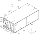
- FIG. 1 is a perspective view schematically showing a battery module housing according to an embodiment of the present disclosure and battery cells accommodated therein
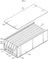
- FIG. 2 is an exploded perspective view showing that a top plate is detached from the battery module housing of FIG. 1
- FIG. 3 is a schematic cross-sectioned view, taken along the line I-I' of FIG. 1
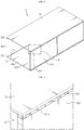
- FIG. 4 is a perspective view showing the battery module housing according to an embodiment of the present disclosure
- FIG. 5 is an enlarged view showing a portion A of FIG. 4 .
- a battery module housing 10 of the present disclosure described below may be understood as a component such as a case for accommodating the battery cells 20.
- the battery cells 20 may be pouch-type secondary batteries.
- the pouch-type secondary batteries may be stacked horizontally or arranged in multiple layers, and then accommodated in the inner space S of the battery module housing 10.
- other components such as a stacking frame for guiding the battery cells 20 to be stacked, a thermistor, and the like may be accommodated together in addition to the battery cells 20.
- the battery module housing 10 may be provided in a rectangular tube shape and include a top plate 100 and a bottom plate 200 forming an upper wall and a lower wall, and a first side plate 300 and a second side plate 400 forming both side walls.
- the battery module housing 10 may provide a mechanical support for the battery cells 20 and protect the battery cells 20 from external impacts.
- the four plates of the battery module housing 10 are preferably made of a metal material to secure rigidity.
- an interconnection board (ICB) assembly for connecting the battery cells 20 in series and/or in parallel may be coupled to the front surface and the rear surface of the battery module housing 10.
- the ICB assembly may include a plurality of bus bars and an ICB housing capable of covering the front surface and the rear surface of the battery module housing 10.
- the electrode leads 21 of the battery cells 20 exposed on the front surface and the rear surface of the battery module housing 10 may be welded to the bus bars to electrically connected and covered with the ICB housing, respectively.
- the first side plate 300 and the second side plate 400 of the battery module housing 10 may have the same thickness and the same shape, and the top plate 100 and the bottom plate 200 may also have the same thickness and the same shape. At this time, the thickness of the first side plate 300 and the second side plate 400 may be relatively thicker than the thickness of the top plate 100 and the bottom plate 200 for the robustness of the battery module housing 10.
- the battery module housing 10 may be manufactured in an adhesive manner so that the four plates 100, 200, 300, 400 may be partially disassembled, unlike the conventional welding method.
- the battery module housing 10 has bonding portions 500 at for spots.
- the bonding portions 500 may be formed as the adhesive 510 is applied along the longitudinal direction (the X-axis direction) at four spots corresponding to spots between both side edges of the top plate 100 opposite to each other and the top surfaces of the first side plate 300 and the second side plate 400 and spots between both side edges of the bottom plate 200 opposite to each other and the bottom surfaces of the first side plate 300 and the second side plate 400.
- the bonding strength of the adhesive 510 may be lowered to about 70 to 85% compared the ordinary state under normal temperature and humidity conditions.
- the disassembling work of the battery module housing 10 is performed in a state where the bonding performance is sufficiently low after the pretreatment process such as storing the battery module in a hot and humid space for a predetermined time or locally applying heat and/or moisture around the bonding portion 500.
- the battery module housing 10 may further include an insulation pad 600 for preventing the heat from being transmitted to the battery cells 20 when heat is locally applied around the bonding portion 500 to weaken the performance of the adhesive 510 of the corresponding bonding portion 500.
- the insulation pad 600 may be attached to the inner surface of each of the top plate 100, the first side plate 300 and the second side plate 400. According to this configuration, even if heat is applied to the top plate 100, the first side plate 300 and the second side plate 400 during the pretreatment process for disassembling the battery module housing 10, the battery cells 20 may be protected from external heat.
- a thermal transfer pad 700 may be attached to the bottom plate 200. As shown in FIG. 3 , even if heat is applied to the upper portion of the battery module housing 10 and transferred to the battery cells 20, the temperature of the battery cells 20 may be properly maintained by discharging the heat to the bottom plate 200 through the thermal transfer pad 700. At this time, if a heatsink (not shown) is additionally connected to the bottom portion of the bottom plate 200, the heat of the battery cells 20 may be more actively removed.
- the thermal transfer pad 700 may be made of any material having a property capable of promoting thermal conductivity and eliminating an air layer between the bottom portion of the battery cells 20 and the bottom plate 200.
- the thermal transfer pad 700 may be replaced by a thermal interface material (TIM) such as thermal grease.
- TIM thermal interface material
- two objects adhered to each other has a relatively high shear strength, compared to the peel strength.
- it is effective to apply a force in a direction perpendicular to the bonding surface.
- a detachable jig 30 may be placed on the front surface and the rear surface of the top plate 100 or the bottom plate 200, and then a force may be applied in a vertical direction to detach the top plate 100 or the bottom plate 200 from the other plates 300, 400.
- the above method is available only after the ICB assembly is disassembled from the battery module housing 10.
- the ICB assembly covers the front surface and the rear surface of the battery module housing 10 in a state of being welded to the electrode leads 21 of the battery cells 20, it may not be easy to remove the ICB assembly first.
- the battery module housing 10 is configured such that the detachable jig 30 is used at the side surface of the battery module housing 10, if the detachable jig 30 is not useable at the front surface and the rear surface of the top plate 100 or the bottom plate 200 due to the ICB assembly (not shown).
- FIGS. 6 and 7 are diagrams corresponding to FIG. 5 , which show the second embodiment and the third embodiment of the present disclosure
- FIGS. 8(a), 8(b) , 9(a) and 9(b) are side views and enlarged views thereof respectively showing battery module housings 10 according to the second embodiment and the third embodiment of the present disclosure
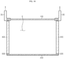
- FIG. 10 is a reference view for illustrating a method of disassembling the battery module housings 10 according to the second embodiment and the third embodiment of the present disclosure.
- the bonding portion 500 according to the second embodiment and the third embodiment of the present disclosure may have a region where the adhesive 510 is not applied at a predetermined location.
- the region where the adhesive 510 is not applied may be used as a detachable jig insertion space 520 in which the detachable jig 30 may be partially inserted.
- the detachable jig insertion space 520 may be provided in plural, and the plurality of detachable jig insertion spaces 520 may be intermittently formed along the longitudinal direction of the first side plate 300 and the second side plate 400.
- the detachable jig insertion space 520 is formed at both the top end and the bottom end of the battery module housing 10. However, it is also possible that the detachable jig insertion space 520 is formed only between the top plate 100 and the first and second side plates 300, 400, namely only at a top end of the module housing 10. In general, internal components of the battery module may be replaced or repaired if the top plate 100 is detached from the battery module housing 10. Thus, it may be desirable to reduce the number of detachable jig insertion spaces 520 by eliminating unnecessary detachable jig insertion spaces.
- the detachable jig insertion space 520 may be filled with a caulking member 540 made of a soft material.
- the caulking member 540 may be, for example, any one of a sealant, a urethane foam and a rubber material in the form of a flexible foam.
- the caulking member 540 of the present disclosure should not be limited to the exemplified substance. In other words, any material may be used as long as it has a soft property and airtightness.
- the detachable jig insertion spaces 520 of the battery module housing 10 may be closed with the caulking member 540.
- the battery module housing 10 may be kept airtight so that moisture or other foreign matter may not flow in through the side portion. If necessary, the caulking member 540 may be removed and the detachable jig 30 can may mounted thereto.
- the detachable jig 30 may be mounted to both side surfaces of the battery module housing 10, namely to the detachable jig insertion spaces 520, to apply a load to the bonding portion 500 in the vertical direction.
- the top plate 100 may be plastic-deformed or broken due to the adhesive force of the other regions.
- the detachable jig insertion space 520 may be extended more widely, compared to the second embodiment. That is, at least one of the first side plate 300 and the second side plate 400 according to the third embodiment of the present disclosure may further have a space expansion portion 530, which is prepared by concavely forming a region to the detachable jig insertion space 520 to have an uneven structure.
- the first side plate 300 and the second side plate 400 may be designed such that the uneven structure is repeated along the longitudinal direction of the top surface and the bottom plate.
- the concave region may be defined as the space expansion portion 530, and the space expansion portion 530 may be utilized as the detachable jig insertion space 520 since the adhesive 510 is not applied thereto.
- the detachable jig insertion space 520 according to the third embodiment may have a larger width than the detachable jig insertion space 520 according to the second embodiment.
- the detachable jig 30 may be inserted into the detachable jig insertion space 520 more easily, compared with the second embodiment. Also, the detachable jig 30 may have a greater thickness than the second embodiment described above, which allows a greater load to be applied to the bonding portion 500.
- FIGS. 11 to 14 The features identical to the former embodiments will not described in detail, and features different from the former embodiments will be described in detail.
- the bonding portion 500' of at least one of the four sites among the bonding portions 500 may be inclined at a predetermined angle toward the inner space S of the battery module housing 10, as compared to the former embodiments.
- the battery module housing 10 may be fabricated in such a way that both side edges of the top plate 100 opposite to each other and the top surfaces of the first side plate 300 and the second side plate 400 are cut at predetermined angles, and the bonding portion 500' may be formed thereon by applying the adhesive 510 to have a predetermined angle ⁇ ) with respect to the horizontal plane.
- the detachable jig insertion spaces 520 may be intermittently provided along the longitudinal direction of the first side plate 300 and the second side plate 400.
- the space expansion portion 530 it is possible to add the space expansion portion 530 by applying an uneven structure to the first side plate 300 and the second side plate 400 as in the third embodiment.
- the detachable jig insertion space 520 may be closed with the caulking member 540, as in the former embodiments.
- the bonding portion 500' at an upper portion of the battery module housing 10 is locally heated to lower the bonding performance of the corresponding region to about 70 to 85%. Then, the caulking member 540 is pushed into the inner space S of the battery module housing 10 or cut it out.
- the detachable jig 30 is inserted into the detachable jig insertion space 520.
- the detachable jig 30 may use any element as long as it may be inserted into the detachable jig insertion space 520.
- more various elements may be selected as the detachable jig 30, compared to the former embodiments.
- the top plate 100 may be detached from the first side plate 300 and the second side plate 400 more easily with a small force, compared to the former embodiments.
- the battery module housing 10 may include a bent portion 110, which is formed to be bent from both edges of at least one of the top plate 100 and the bottom plate 200 and disposed in contact with the outer side surfaces of the first side plate 300 and the second side plate 400, compared to the former embodiments.
- the top plate 100 may be provided to surround the top surfaces and the outer side surfaces of the first side plate 300 and the second side plate 400.
- the bent portion 110 of the top plate 100 may protect the bonding portion 500 not to be exposed to the outside and may also be used as a place where the detachable jig 30 may be mounted during the disassembling operation.
- the detachable jig insertion space 520 is not present at the bonding portion 500 of the battery module housing 10 according to the fifth embodiment. That is, the battery module housing 10 according to the fifth embodiment has the bonding portion 500 where the adhesive 510 is successively applied, between the four plates 100, 200, 300, 400, as in the first embodiment.
- the airtightness is superior at ordinary time, compared to the former embodiments, and if necessary, the top plate 100 may be detached by using the detachable jig 30 at the side surface of the battery module housing 10.
- a battery module according to the present disclosure may include the battery module housing 10 of the present disclosure. Also, in addition to the battery module housing 10, the battery module according to the present disclosure further includes battery cells 20 accommodated in the battery module housing 10, an ICB assembly for electrically connecting the battery cells 20 and sensing voltage characteristics of the battery cells 20, and various devices for controlling charge and discharge of the battery cells such as a BMS, a current sensor and a fuse.
- the battery module may be applied to a vehicle such as an electric vehicle and a hybrid electric vehicle or a power storage system (ESS).
- a vehicle such as an electric vehicle and a hybrid electric vehicle or a power storage system (ESS).
- ESS power storage system
Landscapes
- Chemical & Material Sciences (AREA)
- Chemical Kinetics & Catalysis (AREA)
- Electrochemistry (AREA)
- General Chemical & Material Sciences (AREA)
- Engineering & Computer Science (AREA)
- Manufacturing & Machinery (AREA)
- Battery Mounting, Suspending (AREA)
- Secondary Cells (AREA)
Abstract
Description
- The present disclosure relates to a battery module housing, and more particularly, to a battery module housing manufactured with a structure easy to reuse, recycle and rework, and a battery module including the battery module housing.
- The present application claims priority to Korean Patent Application No.
10-2018-0005922 filed on January 17, 2018 - A battery module may include a plurality of battery cells stacked in one direction and having electrode leads electrically connected in series and/or in parallel, and a battery module housing for packaging the battery cells.
- The battery module housing provides a mechanical support for the battery cells with insufficient mechanical stiffness and serves as a case for protecting the battery cells against external shocks. The battery module housing may be manufactured in various shapes depending on the battery module, and recently is frequently manufactured in a rectangular tube shape, which is referred to as a mono frame.
- The conventional mono frame may be integrally manufactured by extrusion or die casting, or may be manufactured by joining four plates by welding.
- However, if a problem occurs at an internal component of the battery module, for example battery cells or a thermistor interposed between the battery cells to measure the temperature of the cells, since the conventional battery module housing is integrally formed or manufactured by welding, the conventional battery module housing is not easily disassembled, and thus it is very difficult to repair or replace only the component with a problem.
- Moreover, in the conventional battery module, if it is not possible to repair or replace the problem with a problem due to the above structure of the battery module housing, the remaining components that are normally working may not be reused and should be entirely discarded.
- Meanwhile, the battery module housing may also be manufactured by coupling four plates in a snap-fitting manner so that the battery module housing may be reworked. However, the snap-fitting method is not a satisfactory alternative because the coupling portion may be easily damaged even by a small impact and also the sealing property is relatively low compared with the integral-type or welding-type battery module housing. Thus, it is necessary to develop a battery module housing with a new structure which is easy to rework and has advantages of the integral type and the welding type.
- The present disclosure is designed to solve the problems of the related art, and therefore the present disclosure is directed to providing a battery module housing, which has high airtightness and is easy to rework when necessary, and a battery module including the battery module housing.
- However, the objects of the present disclosure are not limited to the above, and objects not mentioned herein may be clearly understood from the present specification by those skilled in the art.
- In one aspect of the present disclosure, there is provided a battery module housing, which includes a top plate and a bottom plate forming an upper wall and a lower wall, and a first side plate and a second side plate forming both side walls, the battery module housing having a rectangular tube shape provided to accommodate battery cells in an inner space thereof,
wherein the battery module housing has bonding portions formed by applying an adhesive along a longitudinal direction to four sites corresponding to sites between both side edges of the top plate opposite to each other and top surfaces of the first side plate and second side plate and sites between both side edges of the bottom plate opposite to each other and bottom surfaces of the first side plate and second side plate. - The bonding portion may have a detachable jig insertion space formed at a predetermined location, and the adhesive may not be applied to the detachable jig insertion space.
- The detachable jig insertion space may be provided in plural, and the plurality of detachable jig insertion spaces may be intermittently formed along the longitudinal direction of the first side plate and the second side plate.
- At least one of the first side plate and the second side plate may have a space expansion portion prepared by concavely forming a region corresponding to the detachable jig insertion space to have an uneven structure.
- The battery module housing may further comprise insulation pads respectively attached to inner surfaces of the top plate, the first side plate and the second side plate; and a thermal transfer pad attached to an inner surface of the bottom plate.
- The battery module housing may further comprise a caulking member filled in the detachable jig insertion space and made of a soft material.
- The bonding portion of at least one of the four sites may be inclined toward the inner space at a predetermined angle.
- At least one of the top plate and the bottom plate may have bent portions bent from both edges thereof and disposed in contact with outer side surfaces of the first side plate and the second side plate.
- In another aspect of the present disclosure, there is also provided a battery module, which comprises the battery module housing described above.
- According to an embodiment of the present disclosure, there is provided a battery module housing which is easy to rework, and thus if a problem occurs at an internal component of a battery module, it is possible to repair and replace the corresponding component and reuse the remaining components.
- According to another embodiment of the present disclosure, the battery module housing is not only easy to rework but also gives airtightness as in the existing welding type.
- The accompanying drawings illustrate a preferred embodiment of the present disclosure and together with the foregoing disclosure, serve to provide further understanding of the technical features of the present disclosure, and thus, the present disclosure is not construed as being limited to the drawing.
-
FIG. 1 is a perspective view schematically showing a battery module housing according to an embodiment of the present disclosure and battery cells accommodated therein. -
FIG. 2 is an exploded perspective view showing that a top plate is detached from the battery module housing ofFIG. 1 . -
FIG. 3 is a schematic cross-sectioned view, taken along the line I-I' ofFIG. 1 . -
FIG. 4 is a perspective view showing the battery module housing according to an embodiment of the present disclosure. -
FIG. 5 is an enlarged view showing a portion A ofFIG. 4 . -
FIGS. 6 and 7 are diagrams corresponding toFIG. 5 , which show the second embodiment and the third embodiment of the present disclosure. -
FIGS. 8(a) and 8(b) are side views respectively showing battery module housings according to the second embodiment and the third embodiment of the present disclosure. -
FIGS. 9(a) and 9(b) are partially enlarged views respectively showing a portion (a) and a portion (b) ofFIG. 8 . -
FIG. 10 is a reference view for illustrating a method of disassembling the battery module housings according to the second embodiment and the third embodiment of the present disclosure. -
FIG. 11 is a cross-sectioned view showing the fourth embodiment of the present disclosure, which corresponds toFIG. 3 . -
FIG. 12 is a partially enlarged view showing the fourth embodiment of the present disclosure, which corresponds toFIG. 5 . -
FIG. 13 is a reference view for illustrating a method of disassembling the battery module housings according to the fourth embodiment of the present disclosure. -
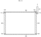
FIG. 14 is a reference view for illustrating a method of disassembling the battery module housings according to the fifth embodiment of the present disclosure. - Hereinafter, preferred embodiments of the present disclosure will be described in detail with reference to the accompanying drawings. Prior to the description, it should be understood that the terms used in the specification and the appended claims should not be construed as limited to general and dictionary meanings, but interpreted based on the meanings and concepts corresponding to technical aspects of the present disclosure on the basis of the principle that the inventor is allowed to define terms appropriately for the best explanation.
- Therefore, the description proposed herein is just a preferable example for the purpose of illustrations only, not intended to limit the scope of the disclosure, so it should be understood that other equivalents and modifications could be made thereto without departing from the scope of the disclosure.
-
FIG. 1 is a perspective view schematically showing a battery module housing according to an embodiment of the present disclosure and battery cells accommodated therein,FIG. 2 is an exploded perspective view showing that a top plate is detached from the battery module housing ofFIG. 1 ,FIG. 3 is a schematic cross-sectioned view, taken along the line I-I' ofFIG. 1 ,FIG. 4 is a perspective view showing the battery module housing according to an embodiment of the present disclosure, andFIG. 5 is an enlarged view showing a portion A ofFIG. 4 . - A battery module housing 10 of the present disclosure described below may be understood as a component such as a case for accommodating the
battery cells 20. Here, thebattery cells 20 may be pouch-type secondary batteries. The pouch-type secondary batteries may be stacked horizontally or arranged in multiple layers, and then accommodated in the inner space S of thebattery module housing 10. Although not shown in detail, other components such as a stacking frame for guiding thebattery cells 20 to be stacked, a thermistor, and the like may be accommodated together in addition to thebattery cells 20. - Referring to
FIGS. 1 to 4 , the battery module housing 10 according to the present disclosure may be provided in a rectangular tube shape and include atop plate 100 and abottom plate 200 forming an upper wall and a lower wall, and afirst side plate 300 and asecond side plate 400 forming both side walls. - The
battery module housing 10 may provide a mechanical support for thebattery cells 20 and protect thebattery cells 20 from external impacts. Thus, the four plates of thebattery module housing 10 are preferably made of a metal material to secure rigidity. - Though not shown, an interconnection board (ICB) assembly for connecting the
battery cells 20 in series and/or in parallel may be coupled to the front surface and the rear surface of thebattery module housing 10. The ICB assembly may include a plurality of bus bars and an ICB housing capable of covering the front surface and the rear surface of thebattery module housing 10. For reference, as shown inFIG. 1 , the electrode leads 21 of thebattery cells 20 exposed on the front surface and the rear surface of thebattery module housing 10 may be welded to the bus bars to electrically connected and covered with the ICB housing, respectively. - The
first side plate 300 and thesecond side plate 400 of thebattery module housing 10 may have the same thickness and the same shape, and thetop plate 100 and thebottom plate 200 may also have the same thickness and the same shape. At this time, the thickness of thefirst side plate 300 and thesecond side plate 400 may be relatively thicker than the thickness of thetop plate 100 and thebottom plate 200 for the robustness of the battery module housing 10. - In particular, the battery module housing 10 according to the present disclosure may be manufactured in an adhesive manner so that the four
plates - Specifically, as shown in
FIGS. 3 to 5 , the battery module housing 10 according to the present disclosure has bondingportions 500 at for spots. Thebonding portions 500 may be formed as the adhesive 510 is applied along the longitudinal direction (the X-axis direction) at four spots corresponding to spots between both side edges of thetop plate 100 opposite to each other and the top surfaces of thefirst side plate 300 and thesecond side plate 400 and spots between both side edges of thebottom plate 200 opposite to each other and the bottom surfaces of thefirst side plate 300 and thesecond side plate 400. - The disassembling operation of the
battery module housing 10 will be described briefly. Generally, the bonding strength of the adhesive 510 may be lowered to about 70 to 85% compared the ordinary state under normal temperature and humidity conditions. Thus, the disassembling work of thebattery module housing 10 is performed in a state where the bonding performance is sufficiently low after the pretreatment process such as storing the battery module in a hot and humid space for a predetermined time or locally applying heat and/or moisture around thebonding portion 500. - Meanwhile, the
battery module housing 10 according to the present disclosure may further include aninsulation pad 600 for preventing the heat from being transmitted to thebattery cells 20 when heat is locally applied around thebonding portion 500 to weaken the performance of the adhesive 510 of thecorresponding bonding portion 500. - For example, as shown in
FIG. 3 , theinsulation pad 600 may be attached to the inner surface of each of thetop plate 100, thefirst side plate 300 and thesecond side plate 400. According to this configuration, even if heat is applied to thetop plate 100, thefirst side plate 300 and thesecond side plate 400 during the pretreatment process for disassembling thebattery module housing 10, thebattery cells 20 may be protected from external heat. - In addition, a
thermal transfer pad 700 may be attached to thebottom plate 200. As shown inFIG. 3 , even if heat is applied to the upper portion of thebattery module housing 10 and transferred to thebattery cells 20, the temperature of thebattery cells 20 may be properly maintained by discharging the heat to thebottom plate 200 through thethermal transfer pad 700. At this time, if a heatsink (not shown) is additionally connected to the bottom portion of thebottom plate 200, the heat of thebattery cells 20 may be more actively removed. - The
thermal transfer pad 700 may be made of any material having a property capable of promoting thermal conductivity and eliminating an air layer between the bottom portion of thebattery cells 20 and thebottom plate 200. Alternatively, thethermal transfer pad 700 may be replaced by a thermal interface material (TIM) such as thermal grease. - Meanwhile, two objects adhered to each other has a relatively high shear strength, compared to the peel strength. Thus, when separating two objects, it is effective to apply a force in a direction perpendicular to the bonding surface.
- For this reason, for the disassembling work of the
battery module housing 10, adetachable jig 30 may be placed on the front surface and the rear surface of thetop plate 100 or thebottom plate 200, and then a force may be applied in a vertical direction to detach thetop plate 100 or thebottom plate 200 from theother plates - However, the above method is available only after the ICB assembly is disassembled from the
battery module housing 10. However, as described above, the ICB assembly covers the front surface and the rear surface of thebattery module housing 10 in a state of being welded to the electrode leads 21 of thebattery cells 20, it may not be easy to remove the ICB assembly first. - The
battery module housing 10 according to the second embodiment and the third embodiment of the present disclosure is configured such that thedetachable jig 30 is used at the side surface of thebattery module housing 10, if thedetachable jig 30 is not useable at the front surface and the rear surface of thetop plate 100 or thebottom plate 200 due to the ICB assembly (not shown). -
FIGS. 6 and 7 are diagrams corresponding toFIG. 5 , which show the second embodiment and the third embodiment of the present disclosure,FIGS. 8(a), 8(b) ,9(a) and 9(b) are side views and enlarged views thereof respectively showingbattery module housings 10 according to the second embodiment and the third embodiment of the present disclosure, andFIG. 10 is a reference view for illustrating a method of disassembling thebattery module housings 10 according to the second embodiment and the third embodiment of the present disclosure. - First, referring to
FIGS. 6 to 10 , common features of thebattery module housings 10 according to the second embodiment and the third embodiment of the present disclosure will be explained. Thebonding portion 500 according to the second embodiment and the third embodiment of the present disclosure may have a region where the adhesive 510 is not applied at a predetermined location. The region where the adhesive 510 is not applied may be used as a detachablejig insertion space 520 in which thedetachable jig 30 may be partially inserted. The detachablejig insertion space 520 may be provided in plural, and the plurality of detachablejig insertion spaces 520 may be intermittently formed along the longitudinal direction of thefirst side plate 300 and thesecond side plate 400. - In these embodiments, the detachable
jig insertion space 520 is formed at both the top end and the bottom end of thebattery module housing 10. However, it is also possible that the detachablejig insertion space 520 is formed only between thetop plate 100 and the first andsecond side plates module housing 10. In general, internal components of the battery module may be replaced or repaired if thetop plate 100 is detached from thebattery module housing 10. Thus, it may be desirable to reduce the number of detachablejig insertion spaces 520 by eliminating unnecessary detachable jig insertion spaces. - The detachable
jig insertion space 520 may be filled with acaulking member 540 made of a soft material. Here, thecaulking member 540 may be, for example, any one of a sealant, a urethane foam and a rubber material in the form of a flexible foam. However, thecaulking member 540 of the present disclosure should not be limited to the exemplified substance. In other words, any material may be used as long as it has a soft property and airtightness. - Specifically, as shown in
FIG. 9 , the detachablejig insertion spaces 520 of thebattery module housing 10 may be closed with thecaulking member 540. Thus, at ordinary time, thebattery module housing 10 may be kept airtight so that moisture or other foreign matter may not flow in through the side portion. If necessary, thecaulking member 540 may be removed and thedetachable jig 30 can may mounted thereto. - According to the configurations of the second embodiment and the third embodiment, as shown in
FIG. 10 , thedetachable jig 30 may be mounted to both side surfaces of thebattery module housing 10, namely to the detachablejig insertion spaces 520, to apply a load to thebonding portion 500 in the vertical direction. At this time, if it is intended to detach thetop plate 100 at once by applying a force at a specific position, thetop plate 100 may be plastic-deformed or broken due to the adhesive force of the other regions. - Thus, it is desired to apply a load in the vertical direction while moving the
detachable jig 30 sequentially along the longitudinal direction of the side plate, so that thetop plate 100 is detached from the top surfaces of thefirst side plate 300 and thesecond side plate 400 in a state where the bonding performance of the adhesive 510 is uniformly weakened. - Meanwhile, in the third embodiment, the detachable
jig insertion space 520 may be extended more widely, compared to the second embodiment. That is, at least one of thefirst side plate 300 and thesecond side plate 400 according to the third embodiment of the present disclosure may further have aspace expansion portion 530, which is prepared by concavely forming a region to the detachablejig insertion space 520 to have an uneven structure. - Specifically, referring to
FIGS. 7 and8(b) , thefirst side plate 300 and thesecond side plate 400 may be designed such that the uneven structure is repeated along the longitudinal direction of the top surface and the bottom plate. Here, the concave region may be defined as thespace expansion portion 530, and thespace expansion portion 530 may be utilized as the detachablejig insertion space 520 since the adhesive 510 is not applied thereto. Thus, the detachablejig insertion space 520 according to the third embodiment may have a larger width than the detachablejig insertion space 520 according to the second embodiment. With this configuration, thedetachable jig 30 may be inserted into the detachablejig insertion space 520 more easily, compared with the second embodiment. Also, thedetachable jig 30 may have a greater thickness than the second embodiment described above, which allows a greater load to be applied to thebonding portion 500. - Subsequently, the fourth embodiment of the present disclosure will be described with reference to
FIGS. 11 to 14 . The features identical to the former embodiments will not described in detail, and features different from the former embodiments will be described in detail. - In this embodiment, the bonding portion 500' of at least one of the four sites among the bonding
portions 500 may be inclined at a predetermined angle toward the inner space S of thebattery module housing 10, as compared to the former embodiments. - For example, as shown in
FIG. 11 , thebattery module housing 10 according to the fourth embodiment may be fabricated in such a way that both side edges of thetop plate 100 opposite to each other and the top surfaces of thefirst side plate 300 and thesecond side plate 400 are cut at predetermined angles, and the bonding portion 500' may be formed thereon by applying the adhesive 510 to have a predetermined angle θ) with respect to the horizontal plane. - As shown in
FIG. 12 , even in the fourth embodiment, the detachablejig insertion spaces 520 may be intermittently provided along the longitudinal direction of thefirst side plate 300 and thesecond side plate 400. Here, it is possible to add thespace expansion portion 530 by applying an uneven structure to thefirst side plate 300 and thesecond side plate 400 as in the third embodiment. Also, the detachablejig insertion space 520 may be closed with thecaulking member 540, as in the former embodiments. - The disassembling operation of the
battery module housing 10 according to the fourth embodiment will be briefly described. First, the bonding portion 500' at an upper portion of thebattery module housing 10 is locally heated to lower the bonding performance of the corresponding region to about 70 to 85%. Then, thecaulking member 540 is pushed into the inner space S of thebattery module housing 10 or cut it out. - Then, as shown in
FIG. 13 , thedetachable jig 30 is inserted into the detachablejig insertion space 520. At this time, thedetachable jig 30 may use any element as long as it may be inserted into the detachablejig insertion space 520. Thus, more various elements may be selected as thedetachable jig 30, compared to the former embodiments. - In particular, according to this embodiment, since the
detachable jig 30 may be inserted diagonally into the bonding portion 500' at the upper portion of thebattery module housing 10, thetop plate 100 may be detached from thefirst side plate 300 and thesecond side plate 400 more easily with a small force, compared to the former embodiments. - Subsequently, a
battery module housing 10 according to the fifth embodiment of the present disclosure will be briefly described with reference toFIG. 14 . - The
battery module housing 10 according to the fifth embodiment may include abent portion 110, which is formed to be bent from both edges of at least one of thetop plate 100 and thebottom plate 200 and disposed in contact with the outer side surfaces of thefirst side plate 300 and thesecond side plate 400, compared to the former embodiments. - For example, as shown in
FIG. 14 , thetop plate 100 according to this embodiment may be provided to surround the top surfaces and the outer side surfaces of thefirst side plate 300 and thesecond side plate 400. Thebent portion 110 of thetop plate 100 may protect thebonding portion 500 not to be exposed to the outside and may also be used as a place where thedetachable jig 30 may be mounted during the disassembling operation. - In particular, the detachable
jig insertion space 520 is not present at thebonding portion 500 of thebattery module housing 10 according to the fifth embodiment. That is, thebattery module housing 10 according to the fifth embodiment has thebonding portion 500 where the adhesive 510 is successively applied, between the fourplates - In this configuration, the airtightness is superior at ordinary time, compared to the former embodiments, and if necessary, the
top plate 100 may be detached by using thedetachable jig 30 at the side surface of thebattery module housing 10. - Meanwhile, a battery module according to the present disclosure may include the
battery module housing 10 of the present disclosure. Also, in addition to thebattery module housing 10, the battery module according to the present disclosure further includesbattery cells 20 accommodated in thebattery module housing 10, an ICB assembly for electrically connecting thebattery cells 20 and sensing voltage characteristics of thebattery cells 20, and various devices for controlling charge and discharge of the battery cells such as a BMS, a current sensor and a fuse. - The battery module may be applied to a vehicle such as an electric vehicle and a hybrid electric vehicle or a power storage system (ESS).
- The present disclosure has been described in detail. However, it should be understood that the detailed description and specific examples, while indicating preferred embodiments of the disclosure, are given by way of illustration only, since various changes and modifications within the scope of the disclosure will become apparent to those skilled in the art from this detailed description.
- Meanwhile, when the terms indicating up, down, left, right, front and rear directions are used in the specification, it is obvious to those skilled in the art that these merely represent relative locations for convenience in explanation and may vary based on a location of an observer or an object to be observed.
Claims (9)
- A battery module housing, which includes a top plate and a bottom plate forming an upper wall and a lower wall, and a first side plate and a second side plate forming both side walls, the battery module housing having a rectangular tube shape provided to accommodate battery cells in an inner space thereof,
wherein the battery module housing has bonding portions formed by applying an adhesive along a longitudinal direction to four sites corresponding to sites between both side edges of the top plate opposite to each other and top surfaces of the first side plate and second side plate and sites between both side edges of the bottom plate opposite to each other and bottom surfaces of the first side plate and second side plate. - The battery module housing according to claim 1,
wherein the bonding portion has a detachable jig insertion space formed at a predetermined location, and the adhesive is not applied to the detachable jig insertion space. - The battery module housing according to claim 2,
wherein the detachable jig insertion space is provided in plural, and the plurality of detachable jig insertion spaces are intermittently formed along the longitudinal direction of the first side plate and the second side plate. - The battery module housing according to claim 2,
wherein at least one of the first side plate and the second side plate has a space expansion portion prepared by concavely forming a region corresponding to the detachable jig insertion space to have an uneven structure. - The battery module housing according to claim 1, further comprising:insulation pads respectively attached to inner surfaces of the top plate, the first side plate and the second side plate; anda thermal transfer pad attached to an inner surface of the bottom plate.
- The battery module housing according to claim 4, further comprising:
a caulking member filled in the detachable jig insertion space and made of a soft material. - The battery module housing according to claim 2,
wherein the bonding portion of at least one of the four sites is inclined toward the inner space at a predetermined angle. - The battery module housing according to claim 2,
wherein at least one of the top plate and the bottom plate has bent portions bent from both edges thereof and disposed in contact with outer side surfaces of the first side plate and the second side plate. - A battery module, comprising a battery module housing defined in any one of claims 1 to 8.
Applications Claiming Priority (2)
| Application Number | Priority Date | Filing Date | Title |
|---|---|---|---|
| KR1020180005922A KR102270269B1 (en) | 2018-01-17 | 2018-01-17 | Battery module housing having a reusable, recyclable or reworkable adhesive structure and Battery module the same |
| PCT/KR2018/015956 WO2019143029A1 (en) | 2018-01-17 | 2018-12-14 | Battery module housing having easily reusable, recyclable, and reworkable adhesion structure and battery module comprising same |
Publications (3)
| Publication Number | Publication Date |
|---|---|
| EP3644398A1 true EP3644398A1 (en) | 2020-04-29 |
| EP3644398A4 EP3644398A4 (en) | 2020-11-04 |
| EP3644398B1 EP3644398B1 (en) | 2025-06-18 |
Family
ID=67302363
Family Applications (1)
| Application Number | Title | Priority Date | Filing Date |
|---|---|---|---|
| EP18901341.0A Active EP3644398B1 (en) | 2018-01-17 | 2018-12-14 | Battery module housing having easily reusable, recyclable, and reworkable adhesion structure and battery module comprising same |
Country Status (9)
| Country | Link |
|---|---|
| US (2) | US11611125B2 (en) |
| EP (1) | EP3644398B1 (en) |
| JP (1) | JP7038944B2 (en) |
| KR (1) | KR102270269B1 (en) |
| CN (1) | CN111095597B (en) |
| ES (1) | ES3035800T3 (en) |
| HU (1) | HUE071935T2 (en) |
| PL (1) | PL3644398T3 (en) |
| WO (1) | WO2019143029A1 (en) |
Cited By (2)
| Publication number | Priority date | Publication date | Assignee | Title |
|---|---|---|---|---|
| US12266817B2 (en) | 2021-02-03 | 2025-04-01 | Cummins Inc. | Battery pack housing |
| US12304099B2 (en) | 2021-05-10 | 2025-05-20 | Volkswagen Aktiengesellschaft | Method for disassembling a battery housing of a high-voltage battery system |
Families Citing this family (14)
| Publication number | Priority date | Publication date | Assignee | Title |
|---|---|---|---|---|
| KR102270269B1 (en) * | 2018-01-17 | 2021-06-28 | 주식회사 엘지에너지솔루션 | Battery module housing having a reusable, recyclable or reworkable adhesive structure and Battery module the same |
| KR102392767B1 (en) * | 2018-12-26 | 2022-04-28 | 주식회사 엘지에너지솔루션 | Battery Module Having Inner Cover |
| KR102754904B1 (en) * | 2019-08-26 | 2025-01-13 | 주식회사 엘지에너지솔루션 | Battery module and battery pack including the same |
| KR102890286B1 (en) * | 2019-11-07 | 2025-11-21 | 주식회사 엘지에너지솔루션 | Battery module and battery pack including the same |
| KR102754508B1 (en) | 2020-03-17 | 2025-01-13 | 주식회사 엘지에너지솔루션 | Battery module and battery pack including the same |
| KR102884652B1 (en) * | 2020-09-28 | 2025-11-10 | 주식회사 엘지에너지솔루션 | Battery pack and vehicle comprising the battery pack |
| KR102907378B1 (en) * | 2020-10-06 | 2025-12-31 | 주식회사 엘지에너지솔루션 | Battery module, battery pack and vehicle comprising the battery module |
| KR102892940B1 (en) * | 2021-01-11 | 2025-11-27 | 주식회사 엘지에너지솔루션 | Battery module and battery pack including the same |
| KR102940431B1 (en) * | 2021-07-09 | 2026-03-16 | 주식회사 엘지에너지솔루션 | Battery module with reinforced safety |
| JP7376539B2 (en) * | 2021-08-03 | 2023-11-08 | プライムプラネットエナジー&ソリューションズ株式会社 | battery |
| KR20230037161A (en) * | 2021-09-09 | 2023-03-16 | 주식회사 엘지에너지솔루션 | Battery module and battery pack including the same |
| US12261315B2 (en) | 2022-04-21 | 2025-03-25 | Ford Global Technologies, Llc | Battery housing assembly for electric vehicles |
| KR20240101055A (en) | 2022-12-23 | 2024-07-02 | 에이치그린파워 주식회사 | A flow variable multi cooling battery module |
| EP4693616A1 (en) * | 2023-11-06 | 2026-02-11 | LG Energy Solution, Ltd. | Battery pack |
Family Cites Families (32)
| Publication number | Priority date | Publication date | Assignee | Title |
|---|---|---|---|---|
| SE429589B (en) * | 1981-04-15 | 1983-09-12 | Andersson Bengt | CABLE SHOES FOR CONNECTING TO A CONISMALLY DESIGNED BATTERY POOL |
| JP2000208115A (en) * | 1999-01-12 | 2000-07-28 | Kenwood Corp | Rechargeable battery storage case |
| JP2000235846A (en) | 1999-02-16 | 2000-08-29 | Tookado:Kk | Battery pack mounting structure |
| JP3524521B2 (en) * | 2001-07-03 | 2004-05-10 | 本田技研工業株式会社 | Passage protection case structure for rear glass for convertible top |
| JP2005056625A (en) * | 2003-07-31 | 2005-03-03 | Sanyo Electric Co Ltd | Battery pack and battery pack disassembling method |
| US7617945B2 (en) * | 2003-09-19 | 2009-11-17 | Gabe Cherian | Pull tab |
| JP2005158308A (en) * | 2003-11-20 | 2005-06-16 | Sony Corp | Battery pack and method of manufacturing the battery pack |
| JP2007213987A (en) * | 2006-02-09 | 2007-08-23 | Toshiba Corp | Battery pack |
| KR101045862B1 (en) * | 2006-09-18 | 2011-07-01 | 주식회사 엘지화학 | Battery pack case for easy assembly and disassembly and battery pack including the same |
| JP5159425B2 (en) | 2008-05-19 | 2013-03-06 | 古河電池株式会社 | Battery module |
| US8916278B2 (en) | 2009-08-12 | 2014-12-23 | Samsung Sdi Co., Ltd. | Heat transfer member for battery pack |
| KR101539788B1 (en) | 2010-12-09 | 2015-07-27 | 주식회사 엘지화학 | Battery case and Pouch type secondary battery |
| JP2014078470A (en) * | 2012-10-12 | 2014-05-01 | Toshiba Corp | Battery module |
| JP6233076B2 (en) | 2014-02-06 | 2017-11-22 | 株式会社豊田自動織機 | Battery module |
| JP6245038B2 (en) | 2014-03-31 | 2017-12-13 | 株式会社Gsユアサ | Power storage device |
| JP6233168B2 (en) * | 2014-04-18 | 2017-11-22 | 株式会社豊田自動織機 | Battery pack |
| US9976778B2 (en) * | 2014-10-13 | 2018-05-22 | Solarcity Corporation | Integrated hook and flashing for photovoltaic module installation on tile roofs |
| KR101808310B1 (en) * | 2014-12-24 | 2017-12-12 | 주식회사 엘지화학 | Compact secondary battery module integrated with BMS |
| CN107835844A (en) * | 2015-07-21 | 2018-03-23 | 索尼公司 | Double-sided adhesive tape, electronic device with double-sided adhesive tape, detachable structure and bonded structure with double-sided adhesive tape |
| KR102050530B1 (en) | 2015-09-24 | 2019-12-02 | 주식회사 엘지화학 | Battery Module |
| KR101935013B1 (en) * | 2015-09-25 | 2019-01-03 | 주식회사 엘지화학 | Battery module, battery pack comprising the battery module and vehicle comprising the battery pack |
| JP6679260B2 (en) | 2015-09-29 | 2020-04-15 | 三洋電機株式会社 | Battery pack |
| KR20170070624A (en) * | 2015-12-14 | 2017-06-22 | 현대오트론 주식회사 | Battery housing |
| EP3399570B1 (en) | 2015-12-28 | 2020-10-28 | Honda Motor Co., Ltd. | Power storage device, housing sealing structure and housing production method |
| KR102097086B1 (en) | 2016-03-16 | 2020-04-03 | 주식회사 엘지화학 | Battery module, battery pack the battery module and vehicle comprising the battery pack |
| KR102112716B1 (en) | 2016-03-16 | 2020-05-19 | 주식회사 엘지화학 | Battery module, battery pack the battery module and vehicle comprising the battery pack |
| KR102519930B1 (en) | 2016-07-07 | 2023-04-11 | 삼성전자주식회사 | Display apparatus |
| DE102017104709A1 (en) * | 2017-03-07 | 2018-09-13 | Dr. Ing. H.C. F. Porsche Aktiengesellschaft | Battery module for use with a high-voltage energy storage |
| CN107579178B (en) | 2017-08-28 | 2019-12-13 | 安徽知之信息科技有限公司 | Conveniently-disassembled storage battery heat preservation device |
| CN207449607U (en) | 2017-11-03 | 2018-06-05 | 北京新能源汽车股份有限公司 | Battery box and vehicle |
| DE102017126949B4 (en) * | 2017-11-16 | 2025-02-27 | Dr. Ing. H.C. F. Porsche Aktiengesellschaft | Battery device for an at least partially electrically operated motor vehicle |
| KR102270269B1 (en) * | 2018-01-17 | 2021-06-28 | 주식회사 엘지에너지솔루션 | Battery module housing having a reusable, recyclable or reworkable adhesive structure and Battery module the same |
-
2018
- 2018-01-17 KR KR1020180005922A patent/KR102270269B1/en active Active
- 2018-12-14 HU HUE18901341A patent/HUE071935T2/en unknown
- 2018-12-14 EP EP18901341.0A patent/EP3644398B1/en active Active
- 2018-12-14 JP JP2019566688A patent/JP7038944B2/en active Active
- 2018-12-14 PL PL18901341.0T patent/PL3644398T3/en unknown
- 2018-12-14 WO PCT/KR2018/015956 patent/WO2019143029A1/en not_active Ceased
- 2018-12-14 US US16/625,453 patent/US11611125B2/en active Active
- 2018-12-14 ES ES18901341T patent/ES3035800T3/en active Active
- 2018-12-14 CN CN201880051027.XA patent/CN111095597B/en active Active
-
2023
- 2023-02-08 US US18/166,274 patent/US12176504B2/en active Active
Cited By (2)
| Publication number | Priority date | Publication date | Assignee | Title |
|---|---|---|---|---|
| US12266817B2 (en) | 2021-02-03 | 2025-04-01 | Cummins Inc. | Battery pack housing |
| US12304099B2 (en) | 2021-05-10 | 2025-05-20 | Volkswagen Aktiengesellschaft | Method for disassembling a battery housing of a high-voltage battery system |
Also Published As
| Publication number | Publication date |
|---|---|
| PL3644398T3 (en) | 2025-08-18 |
| CN111095597A (en) | 2020-05-01 |
| CN111095597B (en) | 2022-09-20 |
| US20200411815A1 (en) | 2020-12-31 |
| KR20190087746A (en) | 2019-07-25 |
| JP2020522111A (en) | 2020-07-27 |
| ES3035800T3 (en) | 2025-09-09 |
| JP7038944B2 (en) | 2022-03-22 |
| EP3644398B1 (en) | 2025-06-18 |
| KR102270269B1 (en) | 2021-06-28 |
| WO2019143029A1 (en) | 2019-07-25 |
| HUE071935T2 (en) | 2025-10-28 |
| US12176504B2 (en) | 2024-12-24 |
| US11611125B2 (en) | 2023-03-21 |
| EP3644398A4 (en) | 2020-11-04 |
| US20230223615A1 (en) | 2023-07-13 |
Similar Documents
| Publication | Publication Date | Title |
|---|---|---|
| US12176504B2 (en) | Battery module housing having easily reusable recyclable, and reworkable adhesion structure and battery module comprising same | |
| KR102698904B1 (en) | Battery module with improved insulation structure and Battery Pack comprising the battry module | |
| EP3343691B1 (en) | Battery module | |
| EP1992026B1 (en) | Battery module | |
| US9640790B2 (en) | Middle or large-sized battery module | |
| JP7106008B2 (en) | battery module | |
| CN101395739B (en) | battery module | |
| US20190280355A1 (en) | Battery module and manufacturing method thereof | |
| CN110447125A (en) | Battery module provided with end frames | |
| KR20170044006A (en) | Battery module including a cooling plate and manufacturing method the same cooling plate | |
| CN107636858A (en) | Battery module and battery pack including the battery module | |
| EP3975325A2 (en) | Battery module and battery pack including the same | |
| US20180034019A1 (en) | Battery module and battery pack comprising same | |
| JP2022551706A (en) | BATTERY MODULE, BATTERY PACK INCLUDING THE SAME, AND BATTERY PACK MANUFACTURING METHOD | |
| KR20160087077A (en) | Battery Pack of Improved Safety | |
| KR102800478B1 (en) | Battery module, battery pack including the same and method of manufacturing battery module | |
| JP2023046518A (en) | battery pack | |
| JP6999238B2 (en) | Battery module and assembled battery | |
| KR20230102553A (en) | Battery Module | |
| CN118266121A (en) | Plug for battery box floor of electric vehicle | |
| JP2024535923A (en) | Battery module, battery pack, automobile, and method for manufacturing battery module | |
| JP7827817B2 (en) | Battery pack and electric vehicle | |
| US20220359941A1 (en) | Module housing for a battery module, a battery module, a side panel unit, and a method for providing a battery module | |
| KR20260052509A (en) | Battery apparatus and manufacturing method of battery apparatus | |
| JP2025100416A (en) | Battery pack and electric vehicle |
Legal Events
| Date | Code | Title | Description |
|---|---|---|---|
| STAA | Information on the status of an ep patent application or granted ep patent |
Free format text: STATUS: THE INTERNATIONAL PUBLICATION HAS BEEN MADE |
|
| PUAI | Public reference made under article 153(3) epc to a published international application that has entered the european phase |
Free format text: ORIGINAL CODE: 0009012 |
|
| STAA | Information on the status of an ep patent application or granted ep patent |
Free format text: STATUS: REQUEST FOR EXAMINATION WAS MADE |
|
| 17P | Request for examination filed |
Effective date: 20200122 |
|
| AK | Designated contracting states |
Kind code of ref document: A1 Designated state(s): AL AT BE BG CH CY CZ DE DK EE ES FI FR GB GR HR HU IE IS IT LI LT LU LV MC MK MT NL NO PL PT RO RS SE SI SK SM TR |
|
| AX | Request for extension of the european patent |
Extension state: BA ME |
|
| A4 | Supplementary search report drawn up and despatched |
Effective date: 20201005 |
|
| RIC1 | Information provided on ipc code assigned before grant |
Ipc: H01M 2/02 20060101ALI20200929BHEP Ipc: H01M 10/42 20060101ALI20200929BHEP Ipc: H01M 2/04 20060101ALI20200929BHEP Ipc: H01M 2/10 20060101AFI20200929BHEP |
|
| DAV | Request for validation of the european patent (deleted) | ||
| DAX | Request for extension of the european patent (deleted) | ||
| RAP1 | Party data changed (applicant data changed or rights of an application transferred) |
Owner name: LG ENERGY SOLUTION LTD. |
|
| STAA | Information on the status of an ep patent application or granted ep patent |
Free format text: STATUS: EXAMINATION IS IN PROGRESS |
|
| 17Q | First examination report despatched |
Effective date: 20220301 |
|
| RAP3 | Party data changed (applicant data changed or rights of an application transferred) |
Owner name: LG ENERGY SOLUTION, LTD. |
|
| REG | Reference to a national code |
Ref country code: DE Ref legal event code: R079 Ref country code: DE Ref legal event code: R079 Ref document number: 602018082793 Country of ref document: DE Free format text: PREVIOUS MAIN CLASS: H01M0002100000 Ipc: H01M0010420000 |
|
| RIC1 | Information provided on ipc code assigned before grant |
Ipc: H01M 50/211 20210101ALI20250213BHEP Ipc: H01M 10/42 20060101AFI20250213BHEP |
|
| GRAJ | Information related to disapproval of communication of intention to grant by the applicant or resumption of examination proceedings by the epo deleted |
Free format text: ORIGINAL CODE: EPIDOSDIGR1 |
|
| GRAP | Despatch of communication of intention to grant a patent |
Free format text: ORIGINAL CODE: EPIDOSNIGR1 |
|
| GRAP | Despatch of communication of intention to grant a patent |
Free format text: ORIGINAL CODE: EPIDOSNIGR1 |
|
| STAA | Information on the status of an ep patent application or granted ep patent |
Free format text: STATUS: GRANT OF PATENT IS INTENDED |
|
| INTG | Intention to grant announced |
Effective date: 20250328 |
|
| GRAS | Grant fee paid |
Free format text: ORIGINAL CODE: EPIDOSNIGR3 |
|
| P01 | Opt-out of the competence of the unified patent court (upc) registered |
Free format text: CASE NUMBER: APP_16822/2025 Effective date: 20250407 |
|
| GRAA | (expected) grant |
Free format text: ORIGINAL CODE: 0009210 |
|
| STAA | Information on the status of an ep patent application or granted ep patent |
Free format text: STATUS: THE PATENT HAS BEEN GRANTED |
|
| AK | Designated contracting states |
Kind code of ref document: B1 Designated state(s): AL AT BE BG CH CY CZ DE DK EE ES FI FR GB GR HR HU IE IS IT LI LT LU LV MC MK MT NL NO PL PT RO RS SE SI SK SM TR |
|
| REG | Reference to a national code |
Ref country code: GB Ref legal event code: FG4D |
|
| REG | Reference to a national code |
Ref country code: CH Ref legal event code: EP |
|
| REG | Reference to a national code |
Ref country code: DE Ref legal event code: R096 Ref document number: 602018082793 Country of ref document: DE |
|
| REG | Reference to a national code |
Ref country code: CH Ref legal event code: EP |
|
| REG | Reference to a national code |
Ref country code: IE Ref legal event code: FG4D |
|
| REG | Reference to a national code |
Ref country code: SE Ref legal event code: TRGR |
|
| REG | Reference to a national code |
Ref country code: ES Ref legal event code: FG2A Ref document number: 3035800 Country of ref document: ES Kind code of ref document: T3 Effective date: 20250909 |
|
| PG25 | Lapsed in a contracting state [announced via postgrant information from national office to epo] |
Ref country code: FI Free format text: LAPSE BECAUSE OF FAILURE TO SUBMIT A TRANSLATION OF THE DESCRIPTION OR TO PAY THE FEE WITHIN THE PRESCRIBED TIME-LIMIT Effective date: 20250618 |
|
| REG | Reference to a national code |
Ref country code: LT Ref legal event code: MG9D |
|
| PG25 | Lapsed in a contracting state [announced via postgrant information from national office to epo] |
Ref country code: NO Free format text: LAPSE BECAUSE OF FAILURE TO SUBMIT A TRANSLATION OF THE DESCRIPTION OR TO PAY THE FEE WITHIN THE PRESCRIBED TIME-LIMIT Effective date: 20250918 Ref country code: GR Free format text: LAPSE BECAUSE OF FAILURE TO SUBMIT A TRANSLATION OF THE DESCRIPTION OR TO PAY THE FEE WITHIN THE PRESCRIBED TIME-LIMIT Effective date: 20250919 |
|
| PG25 | Lapsed in a contracting state [announced via postgrant information from national office to epo] |
Ref country code: BG Free format text: LAPSE BECAUSE OF FAILURE TO SUBMIT A TRANSLATION OF THE DESCRIPTION OR TO PAY THE FEE WITHIN THE PRESCRIBED TIME-LIMIT Effective date: 20250618 |
|
| PG25 | Lapsed in a contracting state [announced via postgrant information from national office to epo] |
Ref country code: HR Free format text: LAPSE BECAUSE OF FAILURE TO SUBMIT A TRANSLATION OF THE DESCRIPTION OR TO PAY THE FEE WITHIN THE PRESCRIBED TIME-LIMIT Effective date: 20250618 |
|
| PG25 | Lapsed in a contracting state [announced via postgrant information from national office to epo] |
Ref country code: RS Free format text: LAPSE BECAUSE OF FAILURE TO SUBMIT A TRANSLATION OF THE DESCRIPTION OR TO PAY THE FEE WITHIN THE PRESCRIBED TIME-LIMIT Effective date: 20250918 |
|
| REG | Reference to a national code |
Ref country code: NL Ref legal event code: MP Effective date: 20250618 |
|
| REG | Reference to a national code |
Ref country code: HU Ref legal event code: AG4A Ref document number: E071935 Country of ref document: HU |
|
| PG25 | Lapsed in a contracting state [announced via postgrant information from national office to epo] |
Ref country code: LV Free format text: LAPSE BECAUSE OF FAILURE TO SUBMIT A TRANSLATION OF THE DESCRIPTION OR TO PAY THE FEE WITHIN THE PRESCRIBED TIME-LIMIT Effective date: 20250618 |
|
| PG25 | Lapsed in a contracting state [announced via postgrant information from national office to epo] |
Ref country code: NL Free format text: LAPSE BECAUSE OF FAILURE TO SUBMIT A TRANSLATION OF THE DESCRIPTION OR TO PAY THE FEE WITHIN THE PRESCRIBED TIME-LIMIT Effective date: 20250618 |
|
| PG25 | Lapsed in a contracting state [announced via postgrant information from national office to epo] |
Ref country code: PT Free format text: LAPSE BECAUSE OF FAILURE TO SUBMIT A TRANSLATION OF THE DESCRIPTION OR TO PAY THE FEE WITHIN THE PRESCRIBED TIME-LIMIT Effective date: 20251020 |
|
| REG | Reference to a national code |
Ref country code: AT Ref legal event code: MK05 Ref document number: 1805079 Country of ref document: AT Kind code of ref document: T Effective date: 20250618 |
|
| PG25 | Lapsed in a contracting state [announced via postgrant information from national office to epo] |
Ref country code: IS Free format text: LAPSE BECAUSE OF FAILURE TO SUBMIT A TRANSLATION OF THE DESCRIPTION OR TO PAY THE FEE WITHIN THE PRESCRIBED TIME-LIMIT Effective date: 20251018 |
|
| PGFP | Annual fee paid to national office [announced via postgrant information from national office to epo] |
Ref country code: DE Payment date: 20251120 Year of fee payment: 8 |
|
| PGFP | Annual fee paid to national office [announced via postgrant information from national office to epo] |
Ref country code: GB Payment date: 20251120 Year of fee payment: 8 |
|
| PG25 | Lapsed in a contracting state [announced via postgrant information from national office to epo] |
Ref country code: AT Free format text: LAPSE BECAUSE OF FAILURE TO SUBMIT A TRANSLATION OF THE DESCRIPTION OR TO PAY THE FEE WITHIN THE PRESCRIBED TIME-LIMIT Effective date: 20250618 Ref country code: SM Free format text: LAPSE BECAUSE OF FAILURE TO SUBMIT A TRANSLATION OF THE DESCRIPTION OR TO PAY THE FEE WITHIN THE PRESCRIBED TIME-LIMIT Effective date: 20250618 |
|
| PGFP | Annual fee paid to national office [announced via postgrant information from national office to epo] |
Ref country code: FR Payment date: 20251125 Year of fee payment: 8 Ref country code: HU Payment date: 20251216 Year of fee payment: 8 |
|
| PGFP | Annual fee paid to national office [announced via postgrant information from national office to epo] |
Ref country code: BE Payment date: 20251120 Year of fee payment: 8 |
|
| PGFP | Annual fee paid to national office [announced via postgrant information from national office to epo] |
Ref country code: SE Payment date: 20251121 Year of fee payment: 8 |
|
| PG25 | Lapsed in a contracting state [announced via postgrant information from national office to epo] |
Ref country code: CZ Free format text: LAPSE BECAUSE OF FAILURE TO SUBMIT A TRANSLATION OF THE DESCRIPTION OR TO PAY THE FEE WITHIN THE PRESCRIBED TIME-LIMIT Effective date: 20250618 |
|
| PGFP | Annual fee paid to national office [announced via postgrant information from national office to epo] |
Ref country code: PL Payment date: 20251124 Year of fee payment: 8 |
|
| PG25 | Lapsed in a contracting state [announced via postgrant information from national office to epo] |
Ref country code: EE Free format text: LAPSE BECAUSE OF FAILURE TO SUBMIT A TRANSLATION OF THE DESCRIPTION OR TO PAY THE FEE WITHIN THE PRESCRIBED TIME-LIMIT Effective date: 20250618 |
|
| PG25 | Lapsed in a contracting state [announced via postgrant information from national office to epo] |
Ref country code: RO Free format text: LAPSE BECAUSE OF FAILURE TO SUBMIT A TRANSLATION OF THE DESCRIPTION OR TO PAY THE FEE WITHIN THE PRESCRIBED TIME-LIMIT Effective date: 20250618 Ref country code: SK Free format text: LAPSE BECAUSE OF FAILURE TO SUBMIT A TRANSLATION OF THE DESCRIPTION OR TO PAY THE FEE WITHIN THE PRESCRIBED TIME-LIMIT Effective date: 20250618 |
|
| REG | Reference to a national code |
Ref country code: DE Ref legal event code: R097 Ref document number: 602018082793 Country of ref document: DE |
|
| PGFP | Annual fee paid to national office [announced via postgrant information from national office to epo] |
Ref country code: ES Payment date: 20260122 Year of fee payment: 8 |
|
| PG25 | Lapsed in a contracting state [announced via postgrant information from national office to epo] |
Ref country code: DK Free format text: LAPSE BECAUSE OF FAILURE TO SUBMIT A TRANSLATION OF THE DESCRIPTION OR TO PAY THE FEE WITHIN THE PRESCRIBED TIME-LIMIT Effective date: 20250618 |
|
| PG25 | Lapsed in a contracting state [announced via postgrant information from national office to epo] |
Ref country code: IT Free format text: LAPSE BECAUSE OF FAILURE TO SUBMIT A TRANSLATION OF THE DESCRIPTION OR TO PAY THE FEE WITHIN THE PRESCRIBED TIME-LIMIT Effective date: 20250618 |
|
| PLBE | No opposition filed within time limit |
Free format text: ORIGINAL CODE: 0009261 |
|
| STAA | Information on the status of an ep patent application or granted ep patent |
Free format text: STATUS: NO OPPOSITION FILED WITHIN TIME LIMIT |
|
| REG | Reference to a national code |
Ref country code: CH Ref legal event code: L10 Free format text: ST27 STATUS EVENT CODE: U-0-0-L10-L00 (AS PROVIDED BY THE NATIONAL OFFICE) Effective date: 20260430 |