EP3644298A1 - Aligning aircraft with runway centerline during takeoff - Google Patents
Aligning aircraft with runway centerline during takeoff Download PDFInfo
- Publication number
- EP3644298A1 EP3644298A1 EP19192870.4A EP19192870A EP3644298A1 EP 3644298 A1 EP3644298 A1 EP 3644298A1 EP 19192870 A EP19192870 A EP 19192870A EP 3644298 A1 EP3644298 A1 EP 3644298A1
- Authority
- EP
- European Patent Office
- Prior art keywords
- aircraft
- angle
- image
- runway
- computing device
- Prior art date
- Legal status (The legal status is an assumption and is not a legal conclusion. Google has not performed a legal analysis and makes no representation as to the accuracy of the status listed.)
- Granted
Links
Images




Classifications
-
- G—PHYSICS
- G05—CONTROLLING; REGULATING
- G05D—SYSTEMS FOR CONTROLLING OR REGULATING NON-ELECTRIC VARIABLES
- G05D1/00—Control of position, course, altitude or attitude of land, water, air or space vehicles, e.g. using automatic pilots
- G05D1/04—Control of altitude or depth
- G05D1/06—Rate of change of altitude or depth
- G05D1/0607—Rate of change of altitude or depth specially adapted for aircraft
- G05D1/0653—Rate of change of altitude or depth specially adapted for aircraft during a phase of take-off or landing
- G05D1/0661—Rate of change of altitude or depth specially adapted for aircraft during a phase of take-off or landing specially adapted for take-off
-
- B—PERFORMING OPERATIONS; TRANSPORTING
- B64—AIRCRAFT; AVIATION; COSMONAUTICS
- B64C—AEROPLANES; HELICOPTERS
- B64C13/00—Control systems or transmitting systems for actuating flying-control surfaces, lift-increasing flaps, air brakes, or spoilers
- B64C13/02—Initiating means
- B64C13/16—Initiating means actuated automatically, e.g. responsive to gust detectors
-
- G—PHYSICS
- G06—COMPUTING OR CALCULATING; COUNTING
- G06V—IMAGE OR VIDEO RECOGNITION OR UNDERSTANDING
- G06V20/00—Scenes; Scene-specific elements
- G06V20/10—Terrestrial scenes
- G06V20/13—Satellite images
-
- B—PERFORMING OPERATIONS; TRANSPORTING
- B64—AIRCRAFT; AVIATION; COSMONAUTICS
- B64C—AEROPLANES; HELICOPTERS
- B64C9/00—Adjustable control surfaces or members, e.g. rudders
-
- G—PHYSICS
- G05—CONTROLLING; REGULATING
- G05D—SYSTEMS FOR CONTROLLING OR REGULATING NON-ELECTRIC VARIABLES
- G05D1/00—Control of position, course, altitude or attitude of land, water, air or space vehicles, e.g. using automatic pilots
- G05D1/0088—Control of position, course, altitude or attitude of land, water, air or space vehicles, e.g. using automatic pilots characterized by the autonomous decision making process, e.g. artificial intelligence, predefined behaviours
-
- G—PHYSICS
- G05—CONTROLLING; REGULATING
- G05D—SYSTEMS FOR CONTROLLING OR REGULATING NON-ELECTRIC VARIABLES
- G05D1/00—Control of position, course, altitude or attitude of land, water, air or space vehicles, e.g. using automatic pilots
- G05D1/02—Control of position or course in two dimensions
- G05D1/0202—Control of position or course in two dimensions specially adapted to aircraft
-
- G—PHYSICS
- G06—COMPUTING OR CALCULATING; COUNTING
- G06T—IMAGE DATA PROCESSING OR GENERATION, IN GENERAL
- G06T7/00—Image analysis
- G06T7/60—Analysis of geometric attributes
-
- G—PHYSICS
- G06—COMPUTING OR CALCULATING; COUNTING
- G06T—IMAGE DATA PROCESSING OR GENERATION, IN GENERAL
- G06T7/00—Image analysis
- G06T7/70—Determining position or orientation of objects or cameras
-
- G—PHYSICS
- G06—COMPUTING OR CALCULATING; COUNTING
- G06T—IMAGE DATA PROCESSING OR GENERATION, IN GENERAL
- G06T7/00—Image analysis
- G06T7/97—Determining parameters from multiple pictures
-
- G—PHYSICS
- G08—SIGNALLING
- G08G—TRAFFIC CONTROL SYSTEMS
- G08G5/00—Traffic control systems for aircraft
- G08G5/20—Arrangements for acquiring, generating, sharing or displaying traffic information
- G08G5/21—Arrangements for acquiring, generating, sharing or displaying traffic information located onboard the aircraft
-
- G—PHYSICS
- G08—SIGNALLING
- G08G—TRAFFIC CONTROL SYSTEMS
- G08G5/00—Traffic control systems for aircraft
- G08G5/50—Navigation or guidance aids
- G08G5/52—Navigation or guidance aids for take-off
-
- B—PERFORMING OPERATIONS; TRANSPORTING
- B64—AIRCRAFT; AVIATION; COSMONAUTICS
- B64D—EQUIPMENT FOR FITTING IN OR TO AIRCRAFT; FLIGHT SUITS; PARACHUTES; ARRANGEMENT OR MOUNTING OF POWER PLANTS OR PROPULSION TRANSMISSIONS IN AIRCRAFT
- B64D2205/00—Aircraft with means for ground manoeuvring, such as taxiing, using an auxiliary thrust system, e.g. jet-engines, propellers or compressed air
-
- B—PERFORMING OPERATIONS; TRANSPORTING
- B64—AIRCRAFT; AVIATION; COSMONAUTICS
- B64U—UNMANNED AERIAL VEHICLES [UAV]; EQUIPMENT THEREFOR
- B64U10/00—Type of UAV
- B64U10/25—Fixed-wing aircraft
-
- B—PERFORMING OPERATIONS; TRANSPORTING
- B64—AIRCRAFT; AVIATION; COSMONAUTICS
- B64U—UNMANNED AERIAL VEHICLES [UAV]; EQUIPMENT THEREFOR
- B64U2101/00—UAVs specially adapted for particular uses or applications
- B64U2101/30—UAVs specially adapted for particular uses or applications for imaging, photography or videography
-
- B—PERFORMING OPERATIONS; TRANSPORTING
- B64—AIRCRAFT; AVIATION; COSMONAUTICS
- B64U—UNMANNED AERIAL VEHICLES [UAV]; EQUIPMENT THEREFOR
- B64U2201/00—UAVs characterised by their flight controls
- B64U2201/10—UAVs characterised by their flight controls autonomous, i.e. by navigating independently from ground or air stations, e.g. by using inertial navigation systems [INS]
-
- G—PHYSICS
- G06—COMPUTING OR CALCULATING; COUNTING
- G06T—IMAGE DATA PROCESSING OR GENERATION, IN GENERAL
- G06T2207/00—Indexing scheme for image analysis or image enhancement
- G06T2207/30—Subject of image; Context of image processing
- G06T2207/30248—Vehicle exterior or interior
- G06T2207/30252—Vehicle exterior; Vicinity of vehicle
- G06T2207/30256—Lane; Road marking
-
- G—PHYSICS
- G08—SIGNALLING
- G08G—TRAFFIC CONTROL SYSTEMS
- G08G5/00—Traffic control systems for aircraft
- G08G5/50—Navigation or guidance aids
- G08G5/55—Navigation or guidance aids for a single aircraft
-
- Y—GENERAL TAGGING OF NEW TECHNOLOGICAL DEVELOPMENTS; GENERAL TAGGING OF CROSS-SECTIONAL TECHNOLOGIES SPANNING OVER SEVERAL SECTIONS OF THE IPC; TECHNICAL SUBJECTS COVERED BY FORMER USPC CROSS-REFERENCE ART COLLECTIONS [XRACs] AND DIGESTS
- Y02—TECHNOLOGIES OR APPLICATIONS FOR MITIGATION OR ADAPTATION AGAINST CLIMATE CHANGE
- Y02T—CLIMATE CHANGE MITIGATION TECHNOLOGIES RELATED TO TRANSPORTATION
- Y02T50/00—Aeronautics or air transport
- Y02T50/80—Energy efficient operational measures, e.g. ground operations or mission management
Definitions
- the present disclosure generally relates to computing devices and methods for aligning an aircraft with a runway centerline during takeoff, and more specifically to computing devices and methods for using image capture and image analysis to align an aircraft with a runway centerline during takeoff.
- Unmanned aerial vehicles UAVs
- UAVs Unmanned aerial vehicles
- Some UAVs are at least partially autonomous (e.g ., autonomous unmanned aerial vehicles (AUAVs)).
- AUAVs present navigational challenges such as automated takeoff. That is, an on-board or otherwise networked computing device often is tasked with steering and throttling the AUAV as it accelerates down a runway during takeoff. More specifically, the AUAV typically maintains its (e.g ., longitudinal) centerline reasonably close to a centerline of the runway as it accelerates down the runway.
- One aspect of the disclosure is a computing device comprising: one or more processors; and a computer readable medium storing instructions that, when executed by the one or more processors, cause the computing device to perform functions for aligning an aircraft with a centerline of a runway during takeoff, the functions comprising: accessing a first image captured by a first camera mounted on a first side of the aircraft; accessing a second image captured by a second camera mounted on a second side of the aircraft that is opposite the first side; determining a first angle between a first marked line on the runway in the first image and a first reference line in the first image; determining a second angle between a second marked line on the runway in the second image and a second reference line in the second image; and based on the first angle and the second angle, moving a control surface of the aircraft such that the aircraft moves closer to the centerline of the runway.
- Another aspect of the disclosure is a non-transitory computer readable medium storing instructions that, when executed by a computing device, cause the computing device to perform functions for aligning an aircraft with a centerline of a runway during takeoff, the functions comprising: accessing a first image captured by a first camera mounted on a first side of the aircraft; accessing a second image captured by a second camera mounted on a second side of the aircraft that is opposite the first side; determining a first angle between a first marked line on the runway in the first image and a first reference line in the first image; determining a second angle between a second marked line on the runway in the second image and a second reference line in the second image; and based on the first angle and the second angle, moving a control surface of the aircraft such that the aircraft moves closer to the centerline of the runway.
- a further aspect of the disclosure is a method for aligning an aircraft with a centerline of a runway during takeoff, the method comprising: accessing a first image captured by a first camera mounted on a first side of the aircraft; accessing a second image captured by a second camera mounted on a second side of the aircraft that is opposite the first side; determining a first angle between a first marked line on the runway in the first image and a first reference line in the first image; determining a second angle between a second marked line on the runway in the second image and a second reference line in the second image; and based on the first angle and the second angle, moving a control surface of the aircraft such that the aircraft moves closer to the centerline of the runway.
- this disclosure includes such methods and computing devices.
- a computing device can access a first image captured by a first camera mounted on a first side of the aircraft and access a second image captured by a second camera mounted on a second side of the aircraft that is opposite the first side.
- the computing device can cause the first camera to capture the first image from a port side (e.g., a wing) of the aircraft and cause the second camera to capture the second image from a starboard side (e.g., a wing) of the aircraft.
- the first image and the second image are typically captured simultaneously during takeoff.
- the first camera and the second camera will typically be mounted on the aircraft to be forward-looking with respect to the aircraft.
- the computing device can determine a first angle between a first marked line on the runway in the first image and a first reference line in the first image. For example, the computing device can determine a first angle between a centerline of the runway in the first image and a horizon in the first image.
- the first marked line can take the form of a left boundary line or a right boundary line of the runway
- the first reference line can take the form of any line that is parallel to the horizon.
- the computing device can identify the first marked line by identifying, from among a plurality of lines of pixels of the first image, a line of pixels having an average color that is closest to a ( e.g ., known) color of the first marked line.
- the computing device can also identify the first reference line by identifying, from among a plurality of lines of pixels of the first image, a line of pixels defining a boundary between a region of the first image having a color that corresponds to the sky and a region of the first image having a color that corresponds to the earth and/or the runway.
- the computing device can also determine a second angle between a second marked line on the runway in the second image and a second reference line in the second image. For example, the computing device can determine a second angle between the centerline of the runway in the second image and the horizon in the second image.
- the second marked line can take the form of a left boundary line or a right boundary line of the runway ( e.g ., the boundary line that is not the first marked line), and the second reference line can take the form of any line that is parallel to the horizon.
- the computing device can identify the second marked line by identifying, from among a plurality of lines of pixels of the second image, a line of pixels having an average color that is closest to a ( e.g ., known) color of the second marked line.
- the computing device can also identify the second reference line by identifying, from among a plurality of lines of pixels of the second image, a line of pixels defining a boundary between a region of the second image having a color that corresponds to the sky and a region of the second image having a color that corresponds to the earth and/or the runway.
- the computing device can, based on the first angle and the second angle, move a control surface (e.g ., a rudder) of the aircraft such that the aircraft moves closer to the centerline of the runway.
- the computing device will generally determine a difference between the first angle and the second angle and use that difference to determine a deflection angle between the control surface and a centerline of the aircraft that tends to cause the aircraft to move closer to the centerline of the runway when the aircraft is moving forward.
- the methods disclosed herein can be advantageous because, when compared to conventional methods of autonomously controlling an aircraft during takeoff, the disclosed methods generally consume less computing resources, involve less burdensome pre-operation calibration, and are less error prone.
- Implementations of this disclosure provide technological improvements that are particular to computer networks and computing devices, for example, computing devices used to autonomously control aircraft during takeoff.
- implementation of this disclosure can eliminate the time spent "training" a computing device with reference images before operation and can reduce the amount of computing resources consumed during operation.
- implementation of this disclosure can reduce the cost and complexity of implementing less efficient methods and systems for autonomously controlling an aircraft during takeoff.
- implementation of this disclosure increases the accuracy and reliability of runway line identification.
- Implementations of this disclosure can thus introduce new and efficient improvements in the ways in which a computing device controls an aircraft during takeoff, and in turn facilitates new and efficient improvements in the ways in which the associated data is used to diagnose and resolve problems.
- the computing device 100 may be or include a mobile device (such as a mobile phone), a desktop computer, a laptop computer, a tablet computer, a server, a network of multiple servers, or similar device(s) that can be configured to perform the functions described herein.
- a mobile device such as a mobile phone
- desktop computer such as a laptop computer
- laptop computer such as a laptop computer
- tablet computer such as a tablet
- server such as a server
- network of multiple servers such as a network of multiple servers, or similar device(s) that can be configured to perform the functions described herein.
- the computing device 100 includes one or more processors 102, a non-transitory computer readable medium 104, a communication interface 106, a display 108, and a user interface 110.
- processors 102 processors 102
- non-transitory computer readable medium 104 the computing device 100 includes one or more processors 102
- communication interface 106 the computing device 100 includes one or more communication interface 106
- display 108 the computing device 100 includes one or more processors 102, a non-transitory computer readable medium 104, a communication interface 106, a display 108, and a user interface 110.
- Components illustrated in Figure 1 may be linked together by a system bus, network, or other connection mechanism 112.
- the one or more processors 102 can be any type of processor(s), such as a microprocessor, a digital signal processor, a multicore processor, etc., coupled to the non-transitory computer readable medium 104.
- the non-transitory computer readable medium 104 can be any type of memory, such as volatile memory like random access memory (RAM), dynamic random access memory (DRAM), static random access memory (SRAM), or nonvolatile memory like read-only memory (ROM), flash memory, magnetic or optical disks, or compact-disc read-only memory (CD-ROM), among other devices used to store data or programs on a temporary or permanent basis.
- non-transitory computer readable medium 104 can be configured to store instructions 114.
- the instructions 114 may be executable by the one or more processors 102 to cause the computing device 100 to perform any of the functions described herein.
- the communication interface 106 can include hardware to enable communication within the computing device 100 and/or between the computing device 100 and one or more other devices.
- the hardware can include transmitters, receivers, and antennas, for example.
- the communication interface 106 can be configured to facilitate communication with one or more other devices, in accordance with one or more wired or wireless communication protocols.
- the communication interface 106 can be configured to facilitate wireless data communication for the computing device 100 according to one or more wireless communication standards, such as one or more Institute of Electrical and Electronics Engineers (IEEE) 801.11 standards, ZigBee standards, Bluetooth standards, etc.
- IEEE Institute of Electrical and Electronics Engineers
- the communication interface 106 can be configured to facilitate wired data communication with one or more other devices.
- the display 108 can be any type of display component configured to display data.
- the display 108 can include a touchscreen display.
- the display 108 can include a flat-panel display, such as a liquid-crystal display (LCD) or a light-emitting diode (LED) display.
- LCD liquid-crystal display
- LED light-emitting diode
- the user interface 110 can include one or more pieces of hardware used to provide data and control signals to the computing device 100.
- the user interface 110 can include a mouse or a pointing device, a keyboard or a keypad, a microphone, a touchpad, or a touchscreen, among other possible types of user input devices.
- the user interface 110 can enable an operator to interact with a graphical user interface (GUI) provided by the computing device 100 ( e.g ., displayed by the display 108).
- GUI graphical user interface
- the computing device 100 is typically part of an aircraft 10.
- the aircraft 10 e.g., an unmanned aerial vehicle
- the aircraft 10 further includes a first camera 304, a second camera 308, and a control surface 322.
- the first camera 304 and the second camera 308 will each typically take the form of a visible light camera, but other forms are possible.
- the control surface 322 can take the form of a rudder, but might also include a flap, an aileron, an elevator, etc.
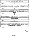
- Figure 2 is a flow diagram of a method 200 for aligning an aircraft with a centerline of a runway during takeoff.
- the method 200 can involve the computing device 100 aligning the aircraft 10 with a centerline 20 of a runway 30 during takeoff.
- the method 200 includes accessing a first image captured by a first camera mounted on a first side of the aircraft.
- the computing device 100 can access a first image 302 captured by the first camera 304 mounted on a first side 12 (e.g., a port side wing) of the aircraft 10.
- the computing device 100 causes the first camera 304 to capture the first image 302.
- the method 200 includes accessing a second image captured by a second camera mounted on a second side of the aircraft that is opposite the first side.
- the computing device 100 can access a second image 306 captured by the second camera 308 mounted on a second side 14 (e.g., a starboard side wing) of the aircraft 10.
- the computing device 100 causes the second camera 308 to capture the second image 306 ( e.g ., simultaneous with capture of the first image 302).
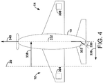
- the first camera 304 and the second camera 308 are typically positioned substantially symmetrically with respect to a centerline 332 of the aircraft 10 and are typically positioned to each have an optical axis that is parallel with the centerline 332.
- the method 200 includes determining a first angle between a first marked line on the runway in the first image and a first reference line in the first image.
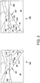
- the computing device 100 can determine a first angle 310 between a first marked line 312 on the runway 30 in the first image 302 and a first reference line 314 in the first image 302.
- the first marked line 312 is the centerline 20 of the runway 30 and the first reference line 314 is a horizon 328 ( e.g ., where the sky and earth meet).
- the first marked line 312 takes on different forms.
- the first reference line 314 could alternatively take the form of any line that is substantially parallel with the horizon 328 in the first image 302.
- the first reference line 314 forms an adjacent side of a right triangle 331 and the first marked line 312 forms a hypotenuse of the right triangle 331 with respect to the first angle 310.
- An opposite side 333 of the right triangle 331 is shown in Figure 3 , but could take the form of any line segment that forms a right angle with the first reference line 314 and has endpoints respectively at the first reference line 314 and the first marked line 312.
- the computing device 100 determines the first angle 310 by calculating the arcsine of the quotient of the length of the opposite side 333 divided by the length of a portion of the first marked line 312 (e.g., the hypotenuse of the right triangle 331).
- the computing device 100 identifies the first marked line 312 by determining that the first marked line 312, a third marked line 324 (e.g., a left boundary line), and a fourth marked line 326 (e.g., a right boundary line) converge at or beyond the horizon 328 within the first image 302. Additionally, the computing device 100 can identify the first marked line 312, the third marked line 324, and the fourth marked line 326 based on determining that the third marked line 324 is to the left of the first marked line 312, and that the first marked line 312 is to the left of the fourth marked line 326.
- a third marked line 324 e.g., a left boundary line
- a fourth marked line 326 e.g., a right boundary line
- the computing device 100 can identify the second marked line 318 (e.g., a right boundary line) by identifying, from among a plurality of lines 342 of pixels of the second image 306, a line of pixels having an average color that is closest to a ( e.g. , known) color of the second marked line 318.
- the computing device 100 can similarly identify the first marked line 312 by identifying, from among a plurality of lines of pixels of the first image 302, a line of pixels having an average color that is closest to a ( e.g. , known) color of the first marked line 312.
- the computing device 100 can analyze lines of pixels to determine their respective average pixel colors (e.g., on the Red Green Blue (RGB) color scale) and determine that the line of the plurality having the average pixel color that is closest to the expected color of the marked line is indeed the marked line.
- RGB Red Green Blue
- the method 200 includes determining a second angle between a second marked line on the runway in the second image and a second reference line in the second image.
- the computing device 100 can determine a second angle 316 between a second marked line 318 on the runway 30 in the second image 306 and a second reference line 320 in the second image 306.
- the second marked line 318 is the centerline 20 of the runway 30 and the second reference line 320 is the horizon 328.
- the second marked line takes on different forms.
- the second reference line 320 could alternatively take the form of any line that is substantially parallel with the horizon 328 in the second image 306.
- the second reference line 320 forms an adjacent side of a right triangle 337 and the second marked line 318 forms a hypotenuse of the right triangle 337 with respect to the second angle 316.
- An opposite side 335 of the right triangle 337 is shown in Figure 3 , but could take the form of any line segment that forms a right angle with the second reference line 320 and has endpoints respectively at the second reference line 320 and the second marked line 318.
- the computing device 100 determines the second angle 316 by calculating the arcsine of the quotient of the length of the opposite side 335 divided by the length of a portion of the second marked line 318 (e.g., the hypotenuse of the right triangle 337).
- the computing device 100 identifies the second marked line 318 by determining that the second marked line 318, the third marked line 324 (e.g., a left boundary line), and the fourth marked line 326 (e.g., a right boundary line) converge at or beyond the horizon 328 within the second image 306. Additionally, the computing device 100 can identify the second marked line 318, the third marked line 324, and the fourth marked line 326 based on determining that the third marked line 324 is to the left of the second marked line 318, and that the second marked line 318 is to the left of the fourth marked line 326.
- Figure 6 illustrates an additional example of the disclosure in which the first marked line 312 takes the form of a left boundary line of the runway 30 and the second marked line 318 takes the form of a right boundary line of the runway 30.
- the computing device 100 can determine the first angle 310 between the first marked line 312 in the first image 302 and the first reference line 314 in the first image 302, in accordance with step 206.
- the first reference line 314 forms an adjacent side of a right triangle and the first marked line 312 forms a hypotenuse of the right triangle with respect to the first angle 310.
- An opposite side of the right triangle is not shown in Figure 6 , but could take the form of any line segment that forms a right angle with the first reference line 314 and has endpoints respectively at the first reference line 314 and the first marked line 312.
- the computing device 100 identifies the first marked line 312 by determining that the first marked line 312, the centerline 20, and a fourth marked line 326 (e.g., a right boundary line) converge at or beyond the horizon 328 within the first image 302. Additionally, the computing device 100 can identify the first marked line 312, the centerline 20, and the fourth marked line 326 based on determining that the first marked line 312 is to the left of the centerline 20, and that the centerline 20 is to the left of the fourth marked line 326.
- a fourth marked line 326 e.g., a right boundary line
- the computing device 100 can determine the second angle 316 between the second marked line 318 in the second image 306 and the second reference line 320 in the second image 306.
- the second reference line 320 forms an adjacent side of a right triangle and the second marked line 318 forms a hypotenuse of the right triangle with respect to the second angle 316.
- An opposite side of the right triangle is not shown in Figure 6 , but could take the form of any line segment that forms a right angle with the second reference line 320 and has endpoints respectively at the second reference line 320 and the second marked line 318.
- the computing device 100 identifies the second marked line 318 by determining that the second marked line 318, the centerline 20, and the third marked line 324 (e.g., a left boundary line) converge at or beyond the horizon 328 within the second image 306. Additionally, the computing device 100 can identify the second marked line 318, the centerline 20, and the third marked line 324 based on determining that the second marked line 318 is to the right of the centerline 20, and that the centerline 20 is to the right of the third marked line 324.
- the second marked line 318, the centerline 20, and the third marked line 324 e.g., a left boundary line
- Figure 7 illustrates an additional example of the disclosure in which the first marked line 312 takes the form of a right boundary line of the runway 30 and the second marked line 318 takes the form of a left boundary line of the runway 30.
- the computing device 100 can determine the first angle 310 between the first marked line 312 in the first image 302 and the first reference line 314 in the first image 302, in accordance with step 206.
- the first reference line 314 forms an adjacent side of a right triangle and the first marked line 312 forms a hypotenuse of the right triangle with respect to the first angle 310.
- An opposite side of the right triangle is not shown in Figure 7 , but could take the form of any line segment that forms a right angle with the first reference line 314 and has endpoints respectively at the first reference line 314 and the first marked line 312.
- the computing device 100 identifies the first marked line 312 by determining that the first marked line 312, the centerline 20, and the third marked line 324 (e.g., a left boundary line) converge at or beyond the horizon 328 within the first image 302. Additionally, the computing device 100 can identify the first marked line 312, the centerline 20, and the third marked line 324 based on determining that the first marked line 312 is to the right of the centerline 20, and that the centerline 20 is to the right of the third marked line 324.
- the first marked line 312, the centerline 20, and the third marked line 324 e.g., a left boundary line
- the computing device 100 can determine the second angle 316 between the second marked line 318 in the second image 306 and the second reference line 320 in the second image 306.
- the second reference line 320 forms an adjacent side of a right triangle and the second marked line 318 forms a hypotenuse of the right triangle with respect to the second angle 316.
- An opposite side of the right triangle is not shown in Figure 7 , but could take the form of any line segment that forms a right angle with the second reference line 320 and has endpoints respectively at the second reference line 320 and the second marked line 318.
- the computing device 100 identifies the second marked line 318 by determining that the second marked line 318, the centerline 20, and the fourth marked line 326 (e.g., a right boundary line) converge at or beyond the horizon 328 within the second image 306. Additionally, the computing device 100 can identify the second marked line 318, the centerline 20, and the fourth marked line 326 based on determining that the second marked line 318 is to the left of the centerline 20, and that the centerline 20 is to the left of the fourth marked line 326.
- the second marked line 318, the centerline 20, and the fourth marked line 326 e.g., a right boundary line
- the method 200 includes, based on the first angle and the second angle, moving a control surface of the aircraft such that the aircraft moves closer to the centerline of the runway.
- the computing device 100 can, based on the first angle 310 and the second angle 316, move the control surface 322 such that the aircraft 10 moves closer to the centerline 20 of the runway 30 ( e.g. , during forward motion of the aircraft 10).
- the computing device 100 can determine a difference between the first angle 310 and the second angle 316 and move the control surface 322 based on the difference.
- Figure 8 illustrates an example in which the first angle 310 is less than the second angle 316 such that the difference of the first angle 310 minus the second angle 316 is negative.
- the aircraft is displaced to the left with respect to the centerline 20 (see Figure 9 ).
- the computing device 100 can move the control surface 322 to the right of the centerline 332 with a deflection angle 330 between the control surface 322 and the centerline 332.
- the deflection angle 330 can be defined by a function that monotonically increases with respect to the difference of the second angle 316 minus the first angle 310. That is, as the difference of the second angle 316 minus the first angle 310 increases, so does the deflection angle 330 in Figure 9 .
- Figure 11 shows one possible relationship between (i) the magnitude of the difference between the first angle 310 and the second angle 316 (e.g.,
- the magnitude of the deflection angle 330 is approximately proportional to
- the magnitude of the deflection angle 330 becomes somewhat non-linear as shown in Figure 11 .
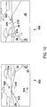
- Figure 10 illustrates an example in which the first angle 310 is greater than the second angle 316 such that the difference of the first angle 310 minus the second angle 316 is positive.
- the aircraft is displaced to the right with respect to the centerline 20 (see Figure 4 ).
- the computing device 100 can move the control surface 322 to the left of the centerline 332 with a deflection angle 330 between the control surface 322 and the centerline 332.
- the deflection angle 330 can be defined by a function that monotonically increases with respect to the difference of the first angle 310 minus the second angle 316. That is, as the difference of the first angle 310 minus the second angle 316 increases, so does the deflection angle 330 in Figure 4 .
- the computing device 100 can determine a direction 334 in which the aircraft is displaced from the centerline 20 of the runway 30 based on the first angle 310 and the second angle 316. Referring to Figure 10 for example, the computing device 100 can determine that the first angle 310 is greater than the second angle 316, and then determine that the aircraft 10 is displaced in the direction 334 (e.g., to the right) with respect to the centerline 20. In this context, the computing device 100 can move the control surface 322 in direction 336 (e.g., to the left) as shown in Figure 4 .
- the computing device 100 can determine that the first angle 310 is less than the second angle 316, and then determine that the aircraft 10 is displaced in the direction 334 (e.g., to the left) with respect to the centerline 20. In this context, the computing device 100 can move the control surface 322 in the direction 336 (e.g., to the right) as shown in Figure 9 .
- the computing device 100 can determine a distance 338 that the aircraft 10 is displaced from the centerline 20 of the runway 30 based on the first angle 310 and the second angle 316.
- the computing device 100 can determine that the aircraft 10 is displaced to the right of the centerline 20 based on the difference between the first angle 310 and the second angle 316. The larger the difference of the first angle 310 minus the second angle 316, the larger the distance 338 in Figure 4 .
- the computing device 100 can move the control surface 322 to the left to form the deflection angle 330 that is defined by a function that monotonically increases with respect to the distance 338.
- the computing device 100 can determine that the aircraft 10 is displaced to the left of the centerline 20 based on the difference between the first angle 310 and the second angle 316. The larger the difference of the second angle 316 minus the first angle 310, the larger the distance 338 in Figure 9 . As such, the computing device 100 can move the control surface 322 to the right to form the deflection angle 330 that is defined by a function that monotonically increases with respect to the distance 338.
- the computing device 100 can account for a heading of the aircraft 10. Referring to Figure 4 and Figure 9 for example, if the heading 340 of the aircraft 10 points away from the centerline 20, the computing device 100 can increase the deflection angle 330. In contrast, if the heading 340 of the aircraft 10 points toward the centerline 20, the computing device 100 can decrease the deflection angle 330.
- the computing device 100 can account for a speed of the aircraft 10 as the aircraft 10 travels down the runway 30. For example, for lower speeds of the aircraft 10, the computing device 100 can increase the deflection angle 330. For higher speeds of the aircraft 10, the computing device 100 can decrease the deflection angle 330.
- the computing device 100 can determine that a particular line marked on the runway is obscured, for example, by snow. Referring to Figure 3 for example, if the computing device 100 determines that either a left boundary line or a right boundary line of the runway 30 is obscured, the computing device 100 can perform the above methods with the centerline 20 taking the form of the first marked line 312 in the first image 302 and taking the form of the second marked line 318 in the second image 306. Referring to Figure 6 for example, if the computing device 100 determines that the centerline 20 of the runway 30 is obscured, the computing device 100 can perform the above methods with a left boundary line of the runway 30 taking the form of the first marked line 312 and a right boundary line taking the form of the second marked line 318.
- the computing device 100 can perform the above methods with a right boundary line of the runway 30 taking the form of the first marked line 312 and a left boundary line taking the form of the second marked line 318.
- Examples of the present disclosure can thus relate to one of the enumerated clauses (EC) listed below.
Landscapes
- Engineering & Computer Science (AREA)
- Physics & Mathematics (AREA)
- General Physics & Mathematics (AREA)
- Aviation & Aerospace Engineering (AREA)
- Theoretical Computer Science (AREA)
- Automation & Control Theory (AREA)
- Remote Sensing (AREA)
- Computer Vision & Pattern Recognition (AREA)
- Radar, Positioning & Navigation (AREA)
- Evolutionary Computation (AREA)
- Business, Economics & Management (AREA)
- Health & Medical Sciences (AREA)
- Artificial Intelligence (AREA)
- Geometry (AREA)
- Game Theory and Decision Science (AREA)
- Medical Informatics (AREA)
- Multimedia (AREA)
- Astronomy & Astrophysics (AREA)
- Traffic Control Systems (AREA)
- Image Analysis (AREA)
- Control Of Position, Course, Altitude, Or Attitude Of Moving Bodies (AREA)
- Image Processing (AREA)
Abstract
Description
- The present disclosure generally relates to computing devices and methods for aligning an aircraft with a runway centerline during takeoff, and more specifically to computing devices and methods for using image capture and image analysis to align an aircraft with a runway centerline during takeoff. Unmanned aerial vehicles (UAVs) continue to become more commonly used in contexts such as national defense, policing, academic research, commerce, and entertainment. Some UAVs are at least partially autonomous (e.g., autonomous unmanned aerial vehicles (AUAVs)). AUAVs present navigational challenges such as automated takeoff. That is, an on-board or otherwise networked computing device often is tasked with steering and throttling the AUAV as it accelerates down a runway during takeoff. More specifically, the AUAV typically maintains its (e.g., longitudinal) centerline reasonably close to a centerline of the runway as it accelerates down the runway.
- One approach for accomplishing this is to use neural networks or other machine learning techniques, but these techniques typically require a computing device to train itself by analyzing thousands of images prior to operation, typically require a high level of computing resources during operation, and could misidentify runway centerlines in cases in which the runway has an atypical appearance. Thus, a need exists for more efficient and reliable methods of aligning an aircraft with a runway centerline during takeoff.
- One aspect of the disclosure is a computing device comprising: one or more processors; and a computer readable medium storing instructions that, when executed by the one or more processors, cause the computing device to perform functions for aligning an aircraft with a centerline of a runway during takeoff, the functions comprising: accessing a first image captured by a first camera mounted on a first side of the aircraft; accessing a second image captured by a second camera mounted on a second side of the aircraft that is opposite the first side; determining a first angle between a first marked line on the runway in the first image and a first reference line in the first image; determining a second angle between a second marked line on the runway in the second image and a second reference line in the second image; and based on the first angle and the second angle, moving a control surface of the aircraft such that the aircraft moves closer to the centerline of the runway.
- Another aspect of the disclosure is a non-transitory computer readable medium storing instructions that, when executed by a computing device, cause the computing device to perform functions for aligning an aircraft with a centerline of a runway during takeoff, the functions comprising: accessing a first image captured by a first camera mounted on a first side of the aircraft; accessing a second image captured by a second camera mounted on a second side of the aircraft that is opposite the first side; determining a first angle between a first marked line on the runway in the first image and a first reference line in the first image; determining a second angle between a second marked line on the runway in the second image and a second reference line in the second image; and based on the first angle and the second angle, moving a control surface of the aircraft such that the aircraft moves closer to the centerline of the runway.
- A further aspect of the disclosure is a method for aligning an aircraft with a centerline of a runway during takeoff, the method comprising: accessing a first image captured by a first camera mounted on a first side of the aircraft; accessing a second image captured by a second camera mounted on a second side of the aircraft that is opposite the first side; determining a first angle between a first marked line on the runway in the first image and a first reference line in the first image; determining a second angle between a second marked line on the runway in the second image and a second reference line in the second image; and based on the first angle and the second angle, moving a control surface of the aircraft such that the aircraft moves closer to the centerline of the runway.
- By the term "about" or "substantially" with reference to amounts or measurement values described herein, it is meant that the recited characteristic, parameter, or value need not be achieved exactly, but that deviations or variations, including for example, tolerances, measurement error, measurement accuracy limitations and other factors known to those of skill in the art, may occur in amounts that do not preclude the effect the characteristic was intended to provide.
- The features, functions, and advantages that have been discussed can be achieved independently in various examples or may be combined in yet other examples further details of which can be seen with reference to the following description and drawings.
- The novel features believed characteristic of the illustrative examples are set forth in the appended claims. The illustrative examples, however, as well as a preferred mode of use, further objectives and descriptions thereof, will best be understood by reference to the following detailed description of an illustrative example of the present disclosure when read in conjunction with the accompanying Figures.
-
Figure 1 is a schematic diagram of a computing device, according to an example. -
Figure 2 is a flow diagram of a method, according to an example. -
Figure 3 shows images captured by respective cameras mounted on an aircraft, according to an example. -
Figure 4 is a schematic overhead view of an aircraft, according to an example. -
Figure 5 shows images captured by respective cameras mounted on an aircraft, according to an example. -
Figure 6 shows images captured by respective cameras mounted on an aircraft, according to an example. -
Figure 7 shows images captured by respective cameras mounted on an aircraft, according to an example. -
Figure 8 shows images captured by respective cameras mounted on an aircraft, according to an example. -
Figure 9 is a schematic overhead view of an aircraft, according to an example. -
Figure 10 shows images captured by respective cameras mounted on an aircraft, according to an example. -
Figure 11 shows a relationship between (i) a magnitude of a difference between a first angle and a second angle that are related to a position of an aircraft on a runway and (ii) a magnitude of a deflection angle of a control surface of the aircraft, according to an example. - As discussed above, there exists a need for more efficient and reliable methods of aligning an aircraft (e.g., a manned aircraft, UAV, or AUAV) with a runway centerline during takeoff. Accordingly, this disclosure includes such methods and computing devices.
- Within examples, a computing device can access a first image captured by a first camera mounted on a first side of the aircraft and access a second image captured by a second camera mounted on a second side of the aircraft that is opposite the first side. For instance, the computing device can cause the first camera to capture the first image from a port side (e.g., a wing) of the aircraft and cause the second camera to capture the second image from a starboard side (e.g., a wing) of the aircraft. The first image and the second image are typically captured simultaneously during takeoff. The first camera and the second camera will typically be mounted on the aircraft to be forward-looking with respect to the aircraft.
- Next, the computing device can determine a first angle between a first marked line on the runway in the first image and a first reference line in the first image. For example, the computing device can determine a first angle between a centerline of the runway in the first image and a horizon in the first image. In other examples, the first marked line can take the form of a left boundary line or a right boundary line of the runway, and the first reference line can take the form of any line that is parallel to the horizon.
- The computing device can identify the first marked line by identifying, from among a plurality of lines of pixels of the first image, a line of pixels having an average color that is closest to a (e.g., known) color of the first marked line. The computing device can also identify the first reference line by identifying, from among a plurality of lines of pixels of the first image, a line of pixels defining a boundary between a region of the first image having a color that corresponds to the sky and a region of the first image having a color that corresponds to the earth and/or the runway.
- The computing device can also determine a second angle between a second marked line on the runway in the second image and a second reference line in the second image. For example, the computing device can determine a second angle between the centerline of the runway in the second image and the horizon in the second image. In other examples, the second marked line can take the form of a left boundary line or a right boundary line of the runway (e.g., the boundary line that is not the first marked line), and the second reference line can take the form of any line that is parallel to the horizon.
- The computing device can identify the second marked line by identifying, from among a plurality of lines of pixels of the second image, a line of pixels having an average color that is closest to a (e.g., known) color of the second marked line. The computing device can also identify the second reference line by identifying, from among a plurality of lines of pixels of the second image, a line of pixels defining a boundary between a region of the second image having a color that corresponds to the sky and a region of the second image having a color that corresponds to the earth and/or the runway.
- Next, the computing device can, based on the first angle and the second angle, move a control surface (e.g., a rudder) of the aircraft such that the aircraft moves closer to the centerline of the runway. The computing device will generally determine a difference between the first angle and the second angle and use that difference to determine a deflection angle between the control surface and a centerline of the aircraft that tends to cause the aircraft to move closer to the centerline of the runway when the aircraft is moving forward.
- The methods disclosed herein can be advantageous because, when compared to conventional methods of autonomously controlling an aircraft during takeoff, the disclosed methods generally consume less computing resources, involve less burdensome pre-operation calibration, and are less error prone.
- Implementations of this disclosure provide technological improvements that are particular to computer networks and computing devices, for example, computing devices used to autonomously control aircraft during takeoff.
- Computing device-specific technological problems, such as the management and use of large quantities of complex data stemming from multiple sources, as well as inefficiency associated therewith, can be wholly or partially solved by the implementations of this disclosure. For example, implementation of this disclosure can eliminate the time spent "training" a computing device with reference images before operation and can reduce the amount of computing resources consumed during operation. Thus, implementation of this disclosure can reduce the cost and complexity of implementing less efficient methods and systems for autonomously controlling an aircraft during takeoff. As another example, implementation of this disclosure increases the accuracy and reliability of runway line identification.
- Implementations of this disclosure can thus introduce new and efficient improvements in the ways in which a computing device controls an aircraft during takeoff, and in turn facilitates new and efficient improvements in the ways in which the associated data is used to diagnose and resolve problems.
- Disclosed examples will now be described more fully hereinafter with reference to the accompanying Drawings, in which some, but not all of the disclosed examples are shown. Indeed, several different examples may be described and should not be construed as limited to the examples set forth herein. Rather, these examples are described so that this disclosure will be thorough and complete and will fully convey the scope of the disclosure to those skilled in the art.
- Referring now to
Figure 1 , acomputing device 100 is illustrated. In some examples, components illustrated inFigure 1 may be distributed across multiple computing devices or computing devices. However, for the sake of example, the components are shown and described as part of thecomputing device 100. Thecomputing device 100 may be or include a mobile device (such as a mobile phone), a desktop computer, a laptop computer, a tablet computer, a server, a network of multiple servers, or similar device(s) that can be configured to perform the functions described herein. - As shown in
Figure 1 , thecomputing device 100 includes one ormore processors 102, a non-transitory computer readable medium 104, acommunication interface 106, adisplay 108, and a user interface 110. Components illustrated inFigure 1 may be linked together by a system bus, network, orother connection mechanism 112. - The one or
more processors 102 can be any type of processor(s), such as a microprocessor, a digital signal processor, a multicore processor, etc., coupled to the non-transitory computer readable medium 104. The non-transitory computer readable medium 104 can be any type of memory, such as volatile memory like random access memory (RAM), dynamic random access memory (DRAM), static random access memory (SRAM), or nonvolatile memory like read-only memory (ROM), flash memory, magnetic or optical disks, or compact-disc read-only memory (CD-ROM), among other devices used to store data or programs on a temporary or permanent basis. - Additionally, the non-transitory computer readable medium 104 can be configured to store
instructions 114. Theinstructions 114 may be executable by the one ormore processors 102 to cause thecomputing device 100 to perform any of the functions described herein. - The
communication interface 106 can include hardware to enable communication within thecomputing device 100 and/or between thecomputing device 100 and one or more other devices. The hardware can include transmitters, receivers, and antennas, for example. Thecommunication interface 106 can be configured to facilitate communication with one or more other devices, in accordance with one or more wired or wireless communication protocols. For example, thecommunication interface 106 can be configured to facilitate wireless data communication for thecomputing device 100 according to one or more wireless communication standards, such as one or more Institute of Electrical and Electronics Engineers (IEEE) 801.11 standards, ZigBee standards, Bluetooth standards, etc. As another example, thecommunication interface 106 can be configured to facilitate wired data communication with one or more other devices. - The
display 108 can be any type of display component configured to display data. As one example, thedisplay 108 can include a touchscreen display. As another example, thedisplay 108 can include a flat-panel display, such as a liquid-crystal display (LCD) or a light-emitting diode (LED) display. - The user interface 110 can include one or more pieces of hardware used to provide data and control signals to the
computing device 100. For instance, the user interface 110 can include a mouse or a pointing device, a keyboard or a keypad, a microphone, a touchpad, or a touchscreen, among other possible types of user input devices. Generally, the user interface 110 can enable an operator to interact with a graphical user interface (GUI) provided by the computing device 100 (e.g., displayed by the display 108). - The
computing device 100 is typically part of anaircraft 10. The aircraft 10 (e.g., an unmanned aerial vehicle) further includes afirst camera 304, asecond camera 308, and acontrol surface 322. - The
first camera 304 and thesecond camera 308 will each typically take the form of a visible light camera, but other forms are possible. Thecontrol surface 322 can take the form of a rudder, but might also include a flap, an aileron, an elevator, etc. -
Figure 2 is a flow diagram of amethod 200 for aligning an aircraft with a centerline of a runway during takeoff. Referring toFigure 3 , themethod 200 can involve thecomputing device 100 aligning theaircraft 10 with acenterline 20 of arunway 30 during takeoff. - Referring to
Figure 2 , atstep 202 themethod 200 includes accessing a first image captured by a first camera mounted on a first side of the aircraft. Referring toFigures 3 and4 , thecomputing device 100 can access afirst image 302 captured by thefirst camera 304 mounted on a first side 12 (e.g., a port side wing) of theaircraft 10. In some examples, thecomputing device 100 causes thefirst camera 304 to capture thefirst image 302. - Referring to
Figure 2 , atstep 204 themethod 200 includes accessing a second image captured by a second camera mounted on a second side of the aircraft that is opposite the first side. Referring toFigures 3 and4 , thecomputing device 100 can access asecond image 306 captured by thesecond camera 308 mounted on a second side 14 (e.g., a starboard side wing) of theaircraft 10. In some examples, thecomputing device 100 causes thesecond camera 308 to capture the second image 306 (e.g., simultaneous with capture of the first image 302). Referring toFigure 4 , thefirst camera 304 and thesecond camera 308 are typically positioned substantially symmetrically with respect to acenterline 332 of theaircraft 10 and are typically positioned to each have an optical axis that is parallel with thecenterline 332. - Referring to
Figure 2 , atstep 206 themethod 200 includes determining a first angle between a first marked line on the runway in the first image and a first reference line in the first image. Referring toFigure 3 , thecomputing device 100 can determine afirst angle 310 between a firstmarked line 312 on therunway 30 in thefirst image 302 and afirst reference line 314 in thefirst image 302. In the example ofFigure 3 , the firstmarked line 312 is thecenterline 20 of therunway 30 and thefirst reference line 314 is a horizon 328 (e.g., where the sky and earth meet). In other examples (e.g., those discussed below), the firstmarked line 312 takes on different forms. Thefirst reference line 314 could alternatively take the form of any line that is substantially parallel with thehorizon 328 in thefirst image 302. - As shown in
Figure 3 , thefirst reference line 314 forms an adjacent side of aright triangle 331 and the firstmarked line 312 forms a hypotenuse of theright triangle 331 with respect to thefirst angle 310. Anopposite side 333 of theright triangle 331 is shown inFigure 3 , but could take the form of any line segment that forms a right angle with thefirst reference line 314 and has endpoints respectively at thefirst reference line 314 and the firstmarked line 312. - In some examples, the
computing device 100 determines thefirst angle 310 by calculating the arcsine of the quotient of the length of theopposite side 333 divided by the length of a portion of the first marked line 312 (e.g., the hypotenuse of the right triangle 331). - In some examples, prior to determining the
first angle 310, thecomputing device 100 identifies the firstmarked line 312 by determining that the firstmarked line 312, a third marked line 324 (e.g., a left boundary line), and a fourth marked line 326 (e.g., a right boundary line) converge at or beyond thehorizon 328 within thefirst image 302. Additionally, thecomputing device 100 can identify the firstmarked line 312, the thirdmarked line 324, and the fourthmarked line 326 based on determining that the thirdmarked line 324 is to the left of the firstmarked line 312, and that the firstmarked line 312 is to the left of the fourthmarked line 326. - Referring to
Figure 5 for example, thecomputing device 100 can identify the second marked line 318 (e.g., a right boundary line) by identifying, from among a plurality oflines 342 of pixels of thesecond image 306, a line of pixels having an average color that is closest to a (e.g., known) color of the secondmarked line 318. Referring toFigure 3 , thecomputing device 100 can similarly identify the firstmarked line 312 by identifying, from among a plurality of lines of pixels of thefirst image 302, a line of pixels having an average color that is closest to a (e.g., known) color of the firstmarked line 312. That is, thecomputing device 100 can analyze lines of pixels to determine their respective average pixel colors (e.g., on the Red Green Blue (RGB) color scale) and determine that the line of the plurality having the average pixel color that is closest to the expected color of the marked line is indeed the marked line. - Referring to
Figure 2 , atstep 208 themethod 200 includes determining a second angle between a second marked line on the runway in the second image and a second reference line in the second image. Referring toFigure 3 for example, thecomputing device 100 can determine asecond angle 316 between a secondmarked line 318 on therunway 30 in thesecond image 306 and asecond reference line 320 in thesecond image 306. In the example ofFigure 3 , the secondmarked line 318 is thecenterline 20 of therunway 30 and thesecond reference line 320 is thehorizon 328. In other examples (e.g., those discussed below), the second marked line takes on different forms. Thesecond reference line 320 could alternatively take the form of any line that is substantially parallel with thehorizon 328 in thesecond image 306. - As shown in
Figure 3 , thesecond reference line 320 forms an adjacent side of aright triangle 337 and the secondmarked line 318 forms a hypotenuse of theright triangle 337 with respect to thesecond angle 316. Anopposite side 335 of theright triangle 337 is shown inFigure 3 , but could take the form of any line segment that forms a right angle with thesecond reference line 320 and has endpoints respectively at thesecond reference line 320 and the secondmarked line 318. - In some examples, the
computing device 100 determines thesecond angle 316 by calculating the arcsine of the quotient of the length of theopposite side 335 divided by the length of a portion of the second marked line 318 (e.g., the hypotenuse of the right triangle 337). - In some examples, prior to determining the
second angle 316, thecomputing device 100 identifies the secondmarked line 318 by determining that the secondmarked line 318, the third marked line 324 (e.g., a left boundary line), and the fourth marked line 326 (e.g., a right boundary line) converge at or beyond thehorizon 328 within thesecond image 306. Additionally, thecomputing device 100 can identify the secondmarked line 318, the thirdmarked line 324, and the fourthmarked line 326 based on determining that the thirdmarked line 324 is to the left of the secondmarked line 318, and that the secondmarked line 318 is to the left of the fourthmarked line 326. -
Figure 6 illustrates an additional example of the disclosure in which the firstmarked line 312 takes the form of a left boundary line of therunway 30 and the secondmarked line 318 takes the form of a right boundary line of therunway 30. As such, thecomputing device 100 can determine thefirst angle 310 between the firstmarked line 312 in thefirst image 302 and thefirst reference line 314 in thefirst image 302, in accordance withstep 206. - As shown in
Figure 6 , thefirst reference line 314 forms an adjacent side of a right triangle and the firstmarked line 312 forms a hypotenuse of the right triangle with respect to thefirst angle 310. An opposite side of the right triangle is not shown inFigure 6 , but could take the form of any line segment that forms a right angle with thefirst reference line 314 and has endpoints respectively at thefirst reference line 314 and the firstmarked line 312. - In some examples, prior to determining the
first angle 310, thecomputing device 100 identifies the firstmarked line 312 by determining that the firstmarked line 312, thecenterline 20, and a fourth marked line 326 (e.g., a right boundary line) converge at or beyond thehorizon 328 within thefirst image 302. Additionally, thecomputing device 100 can identify the firstmarked line 312, thecenterline 20, and the fourthmarked line 326 based on determining that the firstmarked line 312 is to the left of thecenterline 20, and that thecenterline 20 is to the left of the fourthmarked line 326. - Referring back to
Figure 2 , in accordance withstep 208 and as shown inFigure 6 , thecomputing device 100 can determine thesecond angle 316 between the secondmarked line 318 in thesecond image 306 and thesecond reference line 320 in thesecond image 306. - As shown in
Figure 6 , thesecond reference line 320 forms an adjacent side of a right triangle and the secondmarked line 318 forms a hypotenuse of the right triangle with respect to thesecond angle 316. An opposite side of the right triangle is not shown inFigure 6 , but could take the form of any line segment that forms a right angle with thesecond reference line 320 and has endpoints respectively at thesecond reference line 320 and the secondmarked line 318. - In some examples, prior to determining the
second angle 316, thecomputing device 100 identifies the secondmarked line 318 by determining that the secondmarked line 318, thecenterline 20, and the third marked line 324 (e.g., a left boundary line) converge at or beyond thehorizon 328 within thesecond image 306. Additionally, thecomputing device 100 can identify the secondmarked line 318, thecenterline 20, and the thirdmarked line 324 based on determining that the secondmarked line 318 is to the right of thecenterline 20, and that thecenterline 20 is to the right of the thirdmarked line 324. -
Figure 7 illustrates an additional example of the disclosure in which the firstmarked line 312 takes the form of a right boundary line of therunway 30 and the secondmarked line 318 takes the form of a left boundary line of therunway 30. As such, thecomputing device 100 can determine thefirst angle 310 between the firstmarked line 312 in thefirst image 302 and thefirst reference line 314 in thefirst image 302, in accordance withstep 206. - As shown in
Figure 7 , thefirst reference line 314 forms an adjacent side of a right triangle and the firstmarked line 312 forms a hypotenuse of the right triangle with respect to thefirst angle 310. An opposite side of the right triangle is not shown inFigure 7 , but could take the form of any line segment that forms a right angle with thefirst reference line 314 and has endpoints respectively at thefirst reference line 314 and the firstmarked line 312. - In some examples, prior to determining the
first angle 310, thecomputing device 100 identifies the firstmarked line 312 by determining that the firstmarked line 312, thecenterline 20, and the third marked line 324 (e.g., a left boundary line) converge at or beyond thehorizon 328 within thefirst image 302. Additionally, thecomputing device 100 can identify the firstmarked line 312, thecenterline 20, and the thirdmarked line 324 based on determining that the firstmarked line 312 is to the right of thecenterline 20, and that thecenterline 20 is to the right of the thirdmarked line 324. - Referring back to
Figure 2 , in accordance withstep 208 and as shown inFigure 7 , thecomputing device 100 can determine thesecond angle 316 between the secondmarked line 318 in thesecond image 306 and thesecond reference line 320 in thesecond image 306. - As shown in
Figure 7 , thesecond reference line 320 forms an adjacent side of a right triangle and the secondmarked line 318 forms a hypotenuse of the right triangle with respect to thesecond angle 316. An opposite side of the right triangle is not shown inFigure 7 , but could take the form of any line segment that forms a right angle with thesecond reference line 320 and has endpoints respectively at thesecond reference line 320 and the secondmarked line 318. - In some examples, prior to determining the
second angle 316, thecomputing device 100 identifies the secondmarked line 318 by determining that the secondmarked line 318, thecenterline 20, and the fourth marked line 326 (e.g., a right boundary line) converge at or beyond thehorizon 328 within thesecond image 306. Additionally, thecomputing device 100 can identify the secondmarked line 318, thecenterline 20, and the fourthmarked line 326 based on determining that the secondmarked line 318 is to the left of thecenterline 20, and that thecenterline 20 is to the left of the fourthmarked line 326. - Referring to
Figure 2 , atstep 210 themethod 200 includes, based on the first angle and the second angle, moving a control surface of the aircraft such that the aircraft moves closer to the centerline of the runway. Referring toFigure 8 andFigure 9 for example, thecomputing device 100 can, based on thefirst angle 310 and thesecond angle 316, move thecontrol surface 322 such that theaircraft 10 moves closer to thecenterline 20 of the runway 30 (e.g., during forward motion of the aircraft 10). - In some examples, the
computing device 100 can determine a difference between thefirst angle 310 and thesecond angle 316 and move thecontrol surface 322 based on the difference.Figure 8 illustrates an example in which thefirst angle 310 is less than thesecond angle 316 such that the difference of thefirst angle 310 minus thesecond angle 316 is negative. In this example, the aircraft is displaced to the left with respect to the centerline 20 (seeFigure 9 ). As such, thecomputing device 100 can move thecontrol surface 322 to the right of thecenterline 332 with adeflection angle 330 between thecontrol surface 322 and thecenterline 332. In this context, thedeflection angle 330 can be defined by a function that monotonically increases with respect to the difference of thesecond angle 316 minus thefirst angle 310. That is, as the difference of thesecond angle 316 minus thefirst angle 310 increases, so does thedeflection angle 330 inFigure 9 . -
Figure 11 shows one possible relationship between (i) the magnitude of the difference between thefirst angle 310 and the second angle 316 (e.g., |θ1-θ1|) and (ii) the magnitude of the deflection angle 330 (e.g., |θd|). For values of |θ1-θ2| that are less than about 90 degrees (e.g., point 339), the magnitude of thedeflection angle 330 is approximately proportional to |θ1-θ2|. For values of |θ1-θ2| that are greater than about 90 degrees, the magnitude of thedeflection angle 330 becomes somewhat non-linear as shown inFigure 11 . -
Figure 10 illustrates an example in which thefirst angle 310 is greater than thesecond angle 316 such that the difference of thefirst angle 310 minus thesecond angle 316 is positive. In this example, the aircraft is displaced to the right with respect to the centerline 20 (seeFigure 4 ). As such, thecomputing device 100 can move thecontrol surface 322 to the left of thecenterline 332 with adeflection angle 330 between thecontrol surface 322 and thecenterline 332. In this context, thedeflection angle 330 can be defined by a function that monotonically increases with respect to the difference of thefirst angle 310 minus thesecond angle 316. That is, as the difference of thefirst angle 310 minus thesecond angle 316 increases, so does thedeflection angle 330 inFigure 4 . - The
computing device 100 can determine adirection 334 in which the aircraft is displaced from thecenterline 20 of therunway 30 based on thefirst angle 310 and thesecond angle 316. Referring toFigure 10 for example, thecomputing device 100 can determine that thefirst angle 310 is greater than thesecond angle 316, and then determine that theaircraft 10 is displaced in the direction 334 (e.g., to the right) with respect to thecenterline 20. In this context, thecomputing device 100 can move thecontrol surface 322 in direction 336 (e.g., to the left) as shown inFigure 4 . Referring toFigure 8 for example, thecomputing device 100 can determine that thefirst angle 310 is less than thesecond angle 316, and then determine that theaircraft 10 is displaced in the direction 334 (e.g., to the left) with respect to thecenterline 20. In this context, thecomputing device 100 can move thecontrol surface 322 in the direction 336 (e.g., to the right) as shown inFigure 9 . - Referring to the examples of
Figure 4 andFigure 9 , thecomputing device 100 can determine adistance 338 that theaircraft 10 is displaced from thecenterline 20 of therunway 30 based on thefirst angle 310 and thesecond angle 316. InFigure 4 for example, thecomputing device 100 can determine that theaircraft 10 is displaced to the right of thecenterline 20 based on the difference between thefirst angle 310 and thesecond angle 316. The larger the difference of thefirst angle 310 minus thesecond angle 316, the larger thedistance 338 inFigure 4 . As such, thecomputing device 100 can move thecontrol surface 322 to the left to form thedeflection angle 330 that is defined by a function that monotonically increases with respect to thedistance 338. - In
Figure 9 for example, thecomputing device 100 can determine that theaircraft 10 is displaced to the left of thecenterline 20 based on the difference between thefirst angle 310 and thesecond angle 316. The larger the difference of thesecond angle 316 minus thefirst angle 310, the larger thedistance 338 inFigure 9 . As such, thecomputing device 100 can move thecontrol surface 322 to the right to form thedeflection angle 330 that is defined by a function that monotonically increases with respect to thedistance 338. - In some examples, the
computing device 100 can account for a heading of theaircraft 10. Referring toFigure 4 andFigure 9 for example, if the heading 340 of theaircraft 10 points away from thecenterline 20, thecomputing device 100 can increase thedeflection angle 330. In contrast, if the heading 340 of theaircraft 10 points toward thecenterline 20, thecomputing device 100 can decrease thedeflection angle 330. - In some examples, the
computing device 100 can account for a speed of theaircraft 10 as theaircraft 10 travels down therunway 30. For example, for lower speeds of theaircraft 10, thecomputing device 100 can increase thedeflection angle 330. For higher speeds of theaircraft 10, thecomputing device 100 can decrease thedeflection angle 330. - In some examples, the
computing device 100 can determine that a particular line marked on the runway is obscured, for example, by snow. Referring toFigure 3 for example, if thecomputing device 100 determines that either a left boundary line or a right boundary line of therunway 30 is obscured, thecomputing device 100 can perform the above methods with thecenterline 20 taking the form of the firstmarked line 312 in thefirst image 302 and taking the form of the secondmarked line 318 in thesecond image 306. Referring toFigure 6 for example, if thecomputing device 100 determines that thecenterline 20 of therunway 30 is obscured, thecomputing device 100 can perform the above methods with a left boundary line of therunway 30 taking the form of the firstmarked line 312 and a right boundary line taking the form of the secondmarked line 318. Referring toFigure 7 as another example, if thecomputing device 100 determines that thecenterline 20 of therunway 30 is obscured, thecomputing device 100 can perform the above methods with a right boundary line of therunway 30 taking the form of the firstmarked line 312 and a left boundary line taking the form of the secondmarked line 318. - Examples of the present disclosure can thus relate to one of the enumerated clauses (EC) listed below.
- EC 1 is a computing device comprising: one or more processors; and a computer readable medium storing instructions that, when executed by the one or more processors, cause the computing device to perform functions for aligning an aircraft with a centerline of a runway during takeoff, the functions comprising: accessing a first image captured by a first camera mounted on a first side of the aircraft; accessing a second image captured by a second camera mounted on a second side of the aircraft that is opposite the first side; determining a first angle between a first marked line on the runway in the first image and a first reference line in the first image; determining a second angle between a second marked line on the runway in the second image and a second reference line in the second image; and based on the first angle and the second angle, moving a control surface of the aircraft such that the aircraft moves closer to the centerline of the runway.
- EC 2 is the computing device of EC 1, the functions further comprising, prior to determining the first angle, identifying the first marked line by determining that the first marked line, a third marked line, and a fourth marked line converge at or beyond a horizon within the first image.
- EC 3 is the computing device of any of ECs 1-2, wherein the first reference line forms an adjacent side of a right triangle with respect to the first angle, and wherein the first marked line forms a hypotenuse of the right triangle.
- EC 4 is the computing device of any of ECs 1-3, wherein the first marked line is the centerline of the runway, and wherein the second marked line is also the centerline of the runway.
- EC 5 is the computing device of any of ECs 1-3, wherein the first side of the aircraft is a port side of the aircraft, wherein the second side of the aircraft is a starboard side of the aircraft, wherein the first marked line is a left boundary line of the runway, and wherein the second marked line is a right boundary line of the runway.
- EC 6 is the computing device of any of ECs 1-3, wherein the first side of the aircraft is a port side of the aircraft, wherein the second side of the aircraft is a starboard side of the aircraft, wherein the first marked line is a right boundary line of the runway, and wherein the second marked line is a left boundary line of the runway.
- EC 7 is the computing device of any of ECs 1-6, wherein the first reference line is substantially parallel to a horizon in the first image, and wherein the second reference line is substantially parallel to the horizon in the second image.
- EC 8 is the computing device of any of ECs 1-7, wherein the first image and the second image are captured substantially simultaneously.
- EC 9 is the computing device of any of ECs 1-8, wherein the aircraft is an unmanned aerial vehicle.
-
EC 10 is the computing device of any of ECs 1-9, wherein the first camera and the second camera are positioned substantially symmetrically with respect to a centerline of the aircraft. - EC 11 is the computing device of any of ECs 1-10, wherein the control surface is a rudder.
-
EC 12 is the computing device of any of ECs 1-11, the functions further comprising determining a difference between the first angle and the second angle, wherein moving the control surface comprises moving the control surface based on the difference. - EC 13 is the computing device of
EC 12, wherein moving the control surface based on the difference comprises moving the control surface to form a deflection angle between the control surface and a centerline of the aircraft, wherein the deflection angle is defined by a function that monotonically increases with respect to the difference. -
EC 14 is the computing device of any of ECs 1-13, the functions further comprising determining a direction in which the aircraft is displaced from the centerline of the runway based on the first angle and the second angle, wherein moving the control surface comprises moving the control surface such that the control surface is displaced, with respect to a centerline of the aircraft, in a direction that is opposite the determined direction. - EC 15 is the computing device of any of ECs 1-14, the functions further comprising determining a distance that the aircraft is displaced from the centerline of the runway based on the first angle and the second angle, wherein moving the control surface comprises moving the control surface to form a deflection angle between the control surface and a centerline of the aircraft, wherein the deflection angle is defined by a function that monotonically increases with respect to the distance.
- EC 16 is the computing device of any of ECs 1-15, the functions further comprising determining a heading (340) of the aircraft based on the first angle and the second angle, wherein moving the control surface comprises moving the control surface based on the heading.
- EC 17 is the computing device of any of ECs 1-16, the functions further comprising identifying the first marked line by identifying, from among a plurality of lines of pixels of the first image, a line of pixels having an average color that is closest to a color of the first marked line.
- EC 18 is the computing device of any of ECs 1-17, the functions further comprising determining that a third marked line on the runway in the first image is obscured, wherein determining the first angle comprises determining the first angle based on determining that the third marked line on the runway in the first image is obscured.
- EC 19 is a non-transitory computer readable medium storing instructions that, when executed by a computing device, cause the computing device to perform functions for aligning an aircraft with a centerline of a runway during takeoff, the functions comprising: accessing a first image captured by a first camera mounted on a first side of the aircraft; accessing a second image captured by a second camera mounted on a second side of the aircraft that is opposite the first side; determining a first angle between a first marked line on the runway in the first image and a first reference line in the first image; determining a second angle between a second marked line on the runway in the second image and a second reference line in the second image; and based on the first angle and the second angle, moving a control surface of the aircraft such that the aircraft moves closer to the centerline of the runway.
-
EC 20 is a method for aligning an aircraft with a centerline of a runway during takeoff, the method comprising: accessing a first image captured by a first camera mounted on a first side of the aircraft; accessing second image captured by a second camera mounted on a second side of the aircraft that is opposite the first side; determining a first angle between a first marked line on the runway in the first image and a first reference line in the first image; determining a second angle between a second marked line on the runway in the second image and a second reference line in the second image; and based on the first angle and the second angle, moving a control surface of the aircraft such that the aircraft moves closer to the centerline of the runway. - The description of the different advantageous arrangements has been presented for purposes of illustration and description, and is not intended to be exhaustive or limited to the examples in the form disclosed. Many modifications and variations will be apparent to those of ordinary skill in the art. Further, different advantageous examples may describe different advantages as compared to other advantageous examples. The example or examples selected are chosen and described in order to explain the principles of the examples, the practical application, and to enable others of ordinary skill in the art to understand the disclosure for various examples with various modifications as are suited to the particular use contemplated.
Claims (15)
- A computing device (100) comprising:one or more processors (102); anda computer readable medium (104) storing instructions (114) that, when executed by the one or more processors, cause the computing device to perform functions for aligning an aircraft (10) with a centerline (20) of a runway (30) during takeoff, the functions comprising:accessing (202) a first image (302) captured by a first camera (304) mounted on a first side (12) of the aircraft;accessing (204) a second image (306) captured by a second camera (308) mounted on a second side (14) of the aircraft that is opposite the first side;determining (206) a first angle (310) between a first marked line (312) on the runway in the first image and a first reference line (314) in the first image;determining (208) a second angle (316) between a second marked line (318) on the runway in the second image and a second reference line (320) in the second image; andbased on the first angle and the second angle, moving (210) a control surface (322) of the aircraft such that the aircraft moves closer to the centerline of the runway.
- The computing device of claim 1, the functions further comprising, prior to determining the first angle, identifying the first marked line by determining that the first marked line, a third marked line (324), and a fourth marked line (326) converge at or beyond a horizon (328) within the first image.
- The computing device of claim 1 or 2,
wherein the first reference line forms an adjacent side of a right triangle with respect to the first angle, and
wherein the first marked line forms a hypotenuse of the right triangle. - The computing device of any of the preceding claims,
wherein the first marked line is the centerline of the runway, and
wherein the second marked line is also the centerline of the runway. - The computing device of any of the preceding claims,
wherein the first side of the aircraft is a port side of the aircraft,
wherein the second side of the aircraft is a starboard side of the aircraft,
wherein the first marked line is a left boundary line of the runway, and
wherein the second marked line is a right boundary line of the runway. - The computing device of any of the preceding claims,
wherein the first side of the aircraft is a port side of the aircraft,
wherein the second side of the aircraft is a starboard side of the aircraft,
wherein the first marked line is a right boundary line of the runway, and
wherein the second marked line is a left boundary line of the runway. - The computing device of any of the preceding claims,
wherein the first reference line is substantially parallel to a horizon in the first image, and
wherein the second reference line is substantially parallel to the horizon in the second image. - The computing device of any of the preceding claims, wherein the first image and the second image are captured substantially simultaneously.
- The computing device of any of the preceding claims, wherein the aircraft is an unmanned aerial vehicle.
- The computing device of any of the preceding claims, wherein the first camera and the second camera are positioned substantially symmetrically with respect to a centerline (332) of the aircraft.
- The computing device of any of the preceding claims, wherein the control surface is a rudder.
- The computing device of any of the preceding claims, the functions further comprising determining a difference between the first angle and the second angle, wherein moving the control surface comprises moving the control surface based on the difference.
- The computing device of claim 12, wherein moving the control surface based on the difference comprises moving the control surface to form a deflection angle (330) between the control surface and a centerline of the aircraft, wherein the deflection angle is defined by a function that monotonically increases with respect to the difference.
- The computing device of any of the preceding claims, the functions further comprising at least one of:determining a direction (334) in which the aircraft is displaced from the centerline of the runway based on the first angle and the second angle, wherein moving the control surface comprises moving the control surface such that the control surface is displaced, with respect to a centerline of the aircraft, in a direction (336) that is opposite the determined direction;determining a distance (338) that the aircraft is displaced from the centerline of the runway based on the first angle and the second angle, wherein moving the control surface comprises moving the control surface to form a deflection angle between the control surface and a centerline of the aircraft, wherein the deflection angle is defined by a function that monotonically increases with respect to the distance;determining a heading (340) of the aircraft based on the first angle and the second angle, wherein moving the control surface comprises moving the control surface based on the heading;identifying the first marked line by identifying, from among a plurality of lines (342) of pixels of the first image, a line of pixels having an average color that is closest to a color of the first marked line; anddetermining that a third marked line on the runway in the first image is obscured, wherein determining the first angle comprises determining the first angle based on determining that the third marked line on the runway in the first image is obscured.
- A method (200) for aligning an aircraft (10) with a centerline (20) of a runway (30) during takeoff, the method comprising:accessing (202) a first image (302) captured by a first camera (304) mounted on a first side (12) of the aircraft;accessing (204) a second image (306) captured by a second camera (308) mounted on a second side (14) of the aircraft that is opposite the first side;determining (206) a first angle (310) between a first marked line (312) on the runway in the first image and a first reference line (314) in the first image;determining (208) a second angle (316) between a second marked line (318) on the runway in the second image and a second reference line (320) in the second image; andbased on the first angle and the second angle, moving (210) a control surface (322) of the aircraft such that the aircraft moves closer to the centerline of the runway.
Applications Claiming Priority (1)
| Application Number | Priority Date | Filing Date | Title |
|---|---|---|---|
| US16/168,429 US11364992B2 (en) | 2018-10-23 | 2018-10-23 | Aligning aircraft with runway centerline during takeoff |
Publications (2)
| Publication Number | Publication Date |
|---|---|
| EP3644298A1 true EP3644298A1 (en) | 2020-04-29 |
| EP3644298B1 EP3644298B1 (en) | 2021-05-12 |
Family
ID=67659707
Family Applications (1)
| Application Number | Title | Priority Date | Filing Date |
|---|---|---|---|
| EP19192870.4A Active EP3644298B1 (en) | 2018-10-23 | 2019-08-21 | Aligning aircraft with runway centerline during takeoff |
Country Status (4)
| Country | Link |
|---|---|
| US (1) | US11364992B2 (en) |
| EP (1) | EP3644298B1 (en) |
| JP (1) | JP7334090B2 (en) |
| CN (1) | CN111091039B (en) |
Families Citing this family (6)
| Publication number | Priority date | Publication date | Assignee | Title |
|---|---|---|---|---|
| US11074820B2 (en) * | 2018-12-19 | 2021-07-27 | Embraer S.A. | Low/No visibility takeoff system |
| US11335009B2 (en) * | 2020-04-27 | 2022-05-17 | University Of Malta | Method and system for aerodrome taxiway surface marking detection |
| US11995836B2 (en) * | 2020-07-07 | 2024-05-28 | Aurora Flight Sciences Corporation, a subsidiary of The Boeing Company | System and method for performing sky-segmentation |
| US12073837B2 (en) | 2021-06-18 | 2024-08-27 | The Boeing Company | Speech detection using image classification |
| KR20230150181A (en) * | 2022-04-21 | 2023-10-30 | 현대자동차주식회사 | System and method for controlling aerial vehicle |
| CN114863303A (en) * | 2022-05-19 | 2022-08-05 | 中国商用飞机有限责任公司北京民用飞机技术研究中心 | Aircraft heading angle prediction method, device, computer equipment and storage medium |
Citations (4)
| Publication number | Priority date | Publication date | Assignee | Title |
|---|---|---|---|---|
| DE10305993A1 (en) * | 2003-02-12 | 2004-08-26 | Deutsches Zentrum für Luft- und Raumfahrt e.V. | Measurement method for determining the position of an aircraft or motor vehicle relative to the side of a runway or road from an image obtained using a camera that includes at least one edge of the runway or road |
| US20080177427A1 (en) * | 2007-01-19 | 2008-07-24 | Thales | Device and method for measuring dynamic parameters of an aircraft progressing over an airport zone |
| US20130138273A1 (en) * | 2011-11-30 | 2013-05-30 | Honeywell International Inc. | System and method for aligning aircraft and runway headings during takeoff roll |
| US20150142220A1 (en) * | 2013-11-15 | 2015-05-21 | Airbus Operations (Sas) | Method and device for automatically guiding an aircraft taxiing on the ground |
Family Cites Families (15)
| Publication number | Priority date | Publication date | Assignee | Title |
|---|---|---|---|---|
| JP3167752B2 (en) * | 1991-10-22 | 2001-05-21 | 富士重工業株式会社 | Vehicle distance detection device |
| US8698654B2 (en) | 2011-12-28 | 2014-04-15 | Honeywell International Inc. | System and method for selecting images to be displayed |
| DE102012111010A1 (en) | 2012-11-15 | 2014-06-12 | Eads Deutschland Gmbh | Method and device for image-based runway localization |
| FR3016222B1 (en) * | 2014-01-03 | 2016-02-05 | Airbus Operations Sas | METHOD AND APPARATUS FOR VERTICAL GUIDANCE OF AN AIRCRAFT DURING AN APPROACH TO A LANDING TRACK ALONG A LATERAL APPROACH TRACK |
| US9117370B1 (en) * | 2014-03-12 | 2015-08-25 | Honeywell International Inc. | System and method for identifying runway position during an intersection takeoff |
| FR3024127B1 (en) * | 2014-07-25 | 2016-08-26 | Airbus Operations Sas | AUTONOMOUS AUTOMATIC LANDING METHOD AND SYSTEM |
| EP3358295B1 (en) | 2015-09-28 | 2020-10-07 | Kyocera Corporation | Image processing device, stereo camera device, vehicle, and image processing method |
| RU2713958C2 (en) * | 2015-12-17 | 2020-02-11 | Ниссан Мотор Ко., Лтд. | Parking assistance method and device |
| US10399696B2 (en) * | 2016-08-31 | 2019-09-03 | The Boeing Company | Aircraft pilot display system and method of use |
| US20180091797A1 (en) * | 2016-09-27 | 2018-03-29 | The Boeing Company | Apparatus and method of compensating for relative motion of at least two aircraft-mounted cameras |
| WO2018081734A1 (en) * | 2016-10-31 | 2018-05-03 | Advanced Aerial Services, Llc | Modular unmanned aerial vehicle with adjustable center of gravity |
| US10247573B1 (en) * | 2017-03-29 | 2019-04-02 | Rockwell Collins, Inc. | Guidance system and method for low visibility takeoff |
| US10249203B2 (en) * | 2017-04-17 | 2019-04-02 | Rosemount Aerospace Inc. | Method and system for providing docking guidance to a pilot of a taxiing aircraft |
| US10583779B2 (en) * | 2017-10-02 | 2020-03-10 | Magna Electronics Inc. | Parking assist system using backup camera |
| US20210086759A1 (en) * | 2017-12-20 | 2021-03-25 | Nissan Motor Co., Ltd. | Parking Control Method and Parking Control Apparatus |
-
2018
- 2018-10-23 US US16/168,429 patent/US11364992B2/en active Active
-
2019
- 2019-08-21 EP EP19192870.4A patent/EP3644298B1/en active Active
- 2019-08-26 JP JP2019153772A patent/JP7334090B2/en active Active
- 2019-09-29 CN CN201910935459.3A patent/CN111091039B/en active Active
Patent Citations (4)
| Publication number | Priority date | Publication date | Assignee | Title |
|---|---|---|---|---|
| DE10305993A1 (en) * | 2003-02-12 | 2004-08-26 | Deutsches Zentrum für Luft- und Raumfahrt e.V. | Measurement method for determining the position of an aircraft or motor vehicle relative to the side of a runway or road from an image obtained using a camera that includes at least one edge of the runway or road |
| US20080177427A1 (en) * | 2007-01-19 | 2008-07-24 | Thales | Device and method for measuring dynamic parameters of an aircraft progressing over an airport zone |
| US20130138273A1 (en) * | 2011-11-30 | 2013-05-30 | Honeywell International Inc. | System and method for aligning aircraft and runway headings during takeoff roll |
| US20150142220A1 (en) * | 2013-11-15 | 2015-05-21 | Airbus Operations (Sas) | Method and device for automatically guiding an aircraft taxiing on the ground |
Also Published As
| Publication number | Publication date |
|---|---|
| EP3644298B1 (en) | 2021-05-12 |
| CN111091039A (en) | 2020-05-01 |
| US11364992B2 (en) | 2022-06-21 |
| BR102019020843A2 (en) | 2020-12-08 |
| US20200122820A1 (en) | 2020-04-23 |
| CN111091039B (en) | 2025-07-15 |
| JP2020066421A (en) | 2020-04-30 |
| JP7334090B2 (en) | 2023-08-28 |
Similar Documents
| Publication | Publication Date | Title |
|---|---|---|
| US11364992B2 (en) | Aligning aircraft with runway centerline during takeoff | |
| CN112560684B (en) | Lane line detection method, lane line detection device, electronic equipment, storage medium and vehicle | |
| US10379545B2 (en) | Detecting optical discrepancies in captured images | |
| CN113920307A (en) | Model training method, device, equipment, storage medium and image detection method | |
| CN111291650A (en) | Method and device for automatic parking assistance | |
| EP3910533A1 (en) | Method, apparatus, electronic device, and storage medium for monitoring an image acquisition device | |
| EP3955218A2 (en) | Lane line detection method and apparatus, electronic device, computer storage medium, and computer program product | |
| CN116894791B (en) | A visual SLAM method and system for image enhancement under low-light conditions | |
| CN112395972B (en) | A recognition method for power system insulator strings based on UAV image processing | |
| CN111081033A (en) | Method and device for determining vehicle heading angle | |
| CN112489450B (en) | Traffic intersection vehicle flow control method, road side equipment and cloud control platform | |
| Shah et al. | Design and develop an autonomous UAV airship for indoor surveillance and monitoring applications | |
| WO2021056503A1 (en) | Positioning method and apparatus for movable platform, movable platform, and storage medium | |
| WO2020220158A1 (en) | Unmanned aerial vehicle control method, unmanned aerial vehicle, and computer-readable storage medium | |
| CN111309048A (en) | Method for detecting autonomous flight along road by combining multi-rotor unmanned aerial vehicle with road | |
| EP4184450A2 (en) | Horizon detection to support an aircraft on a mission in an environment | |
| BR102019020843B1 (en) | COMPUTING DEVICE AND METHOD FOR ALIGNING AN AIRCRAFT TO A CENTRELINE OF A RUNWAY DURING TAKEOFF | |
| US11922660B2 (en) | Method for determining the positioning of a following aircraft with respect to a leading aircraft flying in front of the following aircraft | |
| US12100203B2 (en) | Above-horizon target tracking | |
| CN118097469A (en) | Pose determination method, device and equipment based on target detection and semantic segmentation | |
| US20250200760A1 (en) | Motion-based target tracking | |
| CN116805397A (en) | Systems and methods for detecting and identifying small objects in images using machine learning algorithms | |
| EP4250251B1 (en) | System and method for detecting and recognizing small objects in images using a machine learning algorithm | |
| US20230306715A1 (en) | System and method for detecting and recognizing small objects in images using a machine learning algorithm | |
| US11704895B2 (en) | Camera data normalization for an autonomous vehicle |
Legal Events
| Date | Code | Title | Description |
|---|---|---|---|
| PUAI | Public reference made under article 153(3) epc to a published international application that has entered the european phase |
Free format text: ORIGINAL CODE: 0009012 |
|
| STAA | Information on the status of an ep patent application or granted ep patent |
Free format text: STATUS: THE APPLICATION HAS BEEN PUBLISHED |
|
| AK | Designated contracting states |
Kind code of ref document: A1 Designated state(s): AL AT BE BG CH CY CZ DE DK EE ES FI FR GB GR HR HU IE IS IT LI LT LU LV MC MK MT NL NO PL PT RO RS SE SI SK SM TR |
|
| AX | Request for extension of the european patent |
Extension state: BA ME |
|
| STAA | Information on the status of an ep patent application or granted ep patent |
Free format text: STATUS: REQUEST FOR EXAMINATION WAS MADE |
|
| 17P | Request for examination filed |
Effective date: 20200903 |
|
| RBV | Designated contracting states (corrected) |
Designated state(s): AL AT BE BG CH CY CZ DE DK EE ES FI FR GB GR HR HU IE IS IT LI LT LU LV MC MK MT NL NO PL PT RO RS SE SI SK SM TR |
|
| GRAP | Despatch of communication of intention to grant a patent |
Free format text: ORIGINAL CODE: EPIDOSNIGR1 |
|
| STAA | Information on the status of an ep patent application or granted ep patent |
Free format text: STATUS: GRANT OF PATENT IS INTENDED |
|
| RIC1 | Information provided on ipc code assigned before grant |
Ipc: G08G 5/00 20060101AFI20201023BHEP |
|
| INTG | Intention to grant announced |
Effective date: 20201125 |
|
| GRAS | Grant fee paid |
Free format text: ORIGINAL CODE: EPIDOSNIGR3 |
|
| GRAA | (expected) grant |
Free format text: ORIGINAL CODE: 0009210 |
|
| STAA | Information on the status of an ep patent application or granted ep patent |
Free format text: STATUS: THE PATENT HAS BEEN GRANTED |
|
| AK | Designated contracting states |
Kind code of ref document: B1 Designated state(s): AL AT BE BG CH CY CZ DE DK EE ES FI FR GB GR HR HU IE IS IT LI LT LU LV MC MK MT NL NO PL PT RO RS SE SI SK SM TR |
|
| REG | Reference to a national code |
Ref country code: GB Ref legal event code: FG4D |
|
| REG | Reference to a national code |
Ref country code: CH Ref legal event code: EP |
|
| REG | Reference to a national code |
Ref country code: DE Ref legal event code: R096 Ref document number: 602019004566 Country of ref document: DE |
|
| REG | Reference to a national code |
Ref country code: IE Ref legal event code: FG4D |
|
| REG | Reference to a national code |
Ref country code: AT Ref legal event code: REF Ref document number: 1392695 Country of ref document: AT Kind code of ref document: T Effective date: 20210615 |
|
| REG | Reference to a national code |
Ref country code: LT Ref legal event code: MG9D |
|
| REG | Reference to a national code |
Ref country code: AT Ref legal event code: MK05 Ref document number: 1392695 Country of ref document: AT Kind code of ref document: T Effective date: 20210512 |
|
| REG | Reference to a national code |
Ref country code: NL Ref legal event code: MP Effective date: 20210512 |
|
| PG25 | Lapsed in a contracting state [announced via postgrant information from national office to epo] |
Ref country code: HR Free format text: LAPSE BECAUSE OF FAILURE TO SUBMIT A TRANSLATION OF THE DESCRIPTION OR TO PAY THE FEE WITHIN THE PRESCRIBED TIME-LIMIT Effective date: 20210512 Ref country code: LT Free format text: LAPSE BECAUSE OF FAILURE TO SUBMIT A TRANSLATION OF THE DESCRIPTION OR TO PAY THE FEE WITHIN THE PRESCRIBED TIME-LIMIT Effective date: 20210512 Ref country code: FI Free format text: LAPSE BECAUSE OF FAILURE TO SUBMIT A TRANSLATION OF THE DESCRIPTION OR TO PAY THE FEE WITHIN THE PRESCRIBED TIME-LIMIT Effective date: 20210512 Ref country code: BG Free format text: LAPSE BECAUSE OF FAILURE TO SUBMIT A TRANSLATION OF THE DESCRIPTION OR TO PAY THE FEE WITHIN THE PRESCRIBED TIME-LIMIT Effective date: 20210812 Ref country code: AT Free format text: LAPSE BECAUSE OF FAILURE TO SUBMIT A TRANSLATION OF THE DESCRIPTION OR TO PAY THE FEE WITHIN THE PRESCRIBED TIME-LIMIT Effective date: 20210512 |
|
| PG25 | Lapsed in a contracting state [announced via postgrant information from national office to epo] |
Ref country code: LV Free format text: LAPSE BECAUSE OF FAILURE TO SUBMIT A TRANSLATION OF THE DESCRIPTION OR TO PAY THE FEE WITHIN THE PRESCRIBED TIME-LIMIT Effective date: 20210512 Ref country code: NO Free format text: LAPSE BECAUSE OF FAILURE TO SUBMIT A TRANSLATION OF THE DESCRIPTION OR TO PAY THE FEE WITHIN THE PRESCRIBED TIME-LIMIT Effective date: 20210812 Ref country code: PL Free format text: LAPSE BECAUSE OF FAILURE TO SUBMIT A TRANSLATION OF THE DESCRIPTION OR TO PAY THE FEE WITHIN THE PRESCRIBED TIME-LIMIT Effective date: 20210512 Ref country code: PT Free format text: LAPSE BECAUSE OF FAILURE TO SUBMIT A TRANSLATION OF THE DESCRIPTION OR TO PAY THE FEE WITHIN THE PRESCRIBED TIME-LIMIT Effective date: 20210913 Ref country code: RS Free format text: LAPSE BECAUSE OF FAILURE TO SUBMIT A TRANSLATION OF THE DESCRIPTION OR TO PAY THE FEE WITHIN THE PRESCRIBED TIME-LIMIT Effective date: 20210512 Ref country code: SE Free format text: LAPSE BECAUSE OF FAILURE TO SUBMIT A TRANSLATION OF THE DESCRIPTION OR TO PAY THE FEE WITHIN THE PRESCRIBED TIME-LIMIT Effective date: 20210512 Ref country code: GR Free format text: LAPSE BECAUSE OF FAILURE TO SUBMIT A TRANSLATION OF THE DESCRIPTION OR TO PAY THE FEE WITHIN THE PRESCRIBED TIME-LIMIT Effective date: 20210813 Ref country code: IS Free format text: LAPSE BECAUSE OF FAILURE TO SUBMIT A TRANSLATION OF THE DESCRIPTION OR TO PAY THE FEE WITHIN THE PRESCRIBED TIME-LIMIT Effective date: 20210912 |
|
| PG25 | Lapsed in a contracting state [announced via postgrant information from national office to epo] |
Ref country code: NL Free format text: LAPSE BECAUSE OF FAILURE TO SUBMIT A TRANSLATION OF THE DESCRIPTION OR TO PAY THE FEE WITHIN THE PRESCRIBED TIME-LIMIT Effective date: 20210512 |
|
| PG25 | Lapsed in a contracting state [announced via postgrant information from national office to epo] |
Ref country code: SM Free format text: LAPSE BECAUSE OF FAILURE TO SUBMIT A TRANSLATION OF THE DESCRIPTION OR TO PAY THE FEE WITHIN THE PRESCRIBED TIME-LIMIT Effective date: 20210512 Ref country code: RO Free format text: LAPSE BECAUSE OF FAILURE TO SUBMIT A TRANSLATION OF THE DESCRIPTION OR TO PAY THE FEE WITHIN THE PRESCRIBED TIME-LIMIT Effective date: 20210512 Ref country code: CZ Free format text: LAPSE BECAUSE OF FAILURE TO SUBMIT A TRANSLATION OF THE DESCRIPTION OR TO PAY THE FEE WITHIN THE PRESCRIBED TIME-LIMIT Effective date: 20210512 Ref country code: DK Free format text: LAPSE BECAUSE OF FAILURE TO SUBMIT A TRANSLATION OF THE DESCRIPTION OR TO PAY THE FEE WITHIN THE PRESCRIBED TIME-LIMIT Effective date: 20210512 Ref country code: ES Free format text: LAPSE BECAUSE OF FAILURE TO SUBMIT A TRANSLATION OF THE DESCRIPTION OR TO PAY THE FEE WITHIN THE PRESCRIBED TIME-LIMIT Effective date: 20210512 Ref country code: EE Free format text: LAPSE BECAUSE OF FAILURE TO SUBMIT A TRANSLATION OF THE DESCRIPTION OR TO PAY THE FEE WITHIN THE PRESCRIBED TIME-LIMIT Effective date: 20210512 Ref country code: SK Free format text: LAPSE BECAUSE OF FAILURE TO SUBMIT A TRANSLATION OF THE DESCRIPTION OR TO PAY THE FEE WITHIN THE PRESCRIBED TIME-LIMIT Effective date: 20210512 |
|
| REG | Reference to a national code |
Ref country code: DE Ref legal event code: R097 Ref document number: 602019004566 Country of ref document: DE |
|
| PLBE | No opposition filed within time limit |
Free format text: ORIGINAL CODE: 0009261 |
|
| STAA | Information on the status of an ep patent application or granted ep patent |
Free format text: STATUS: NO OPPOSITION FILED WITHIN TIME LIMIT |
|
| PG25 | Lapsed in a contracting state [announced via postgrant information from national office to epo] |
Ref country code: MC Free format text: LAPSE BECAUSE OF FAILURE TO SUBMIT A TRANSLATION OF THE DESCRIPTION OR TO PAY THE FEE WITHIN THE PRESCRIBED TIME-LIMIT Effective date: 20210512 |
|
| 26N | No opposition filed |
Effective date: 20220215 |
|
| REG | Reference to a national code |
Ref country code: BE Ref legal event code: MM Effective date: 20210831 |
|
| PG25 | Lapsed in a contracting state [announced via postgrant information from national office to epo] |
Ref country code: IS Free format text: LAPSE BECAUSE OF FAILURE TO SUBMIT A TRANSLATION OF THE DESCRIPTION OR TO PAY THE FEE WITHIN THE PRESCRIBED TIME-LIMIT Effective date: 20210912 Ref country code: LU Free format text: LAPSE BECAUSE OF NON-PAYMENT OF DUE FEES Effective date: 20210821 Ref country code: AL Free format text: LAPSE BECAUSE OF FAILURE TO SUBMIT A TRANSLATION OF THE DESCRIPTION OR TO PAY THE FEE WITHIN THE PRESCRIBED TIME-LIMIT Effective date: 20210512 |
|
| PG25 | Lapsed in a contracting state [announced via postgrant information from national office to epo] |
Ref country code: IT Free format text: LAPSE BECAUSE OF FAILURE TO SUBMIT A TRANSLATION OF THE DESCRIPTION OR TO PAY THE FEE WITHIN THE PRESCRIBED TIME-LIMIT Effective date: 20210512 Ref country code: IE Free format text: LAPSE BECAUSE OF NON-PAYMENT OF DUE FEES Effective date: 20210821 Ref country code: BE Free format text: LAPSE BECAUSE OF NON-PAYMENT OF DUE FEES Effective date: 20210831 |
|
| REG | Reference to a national code |
Ref country code: CH Ref legal event code: PL |
|
| PG25 | Lapsed in a contracting state [announced via postgrant information from national office to epo] |
Ref country code: LI Free format text: LAPSE BECAUSE OF NON-PAYMENT OF DUE FEES Effective date: 20220831 Ref country code: CH Free format text: LAPSE BECAUSE OF NON-PAYMENT OF DUE FEES Effective date: 20220831 |
|
| P01 | Opt-out of the competence of the unified patent court (upc) registered |
Effective date: 20230516 |
|
| PG25 | Lapsed in a contracting state [announced via postgrant information from national office to epo] |
Ref country code: CY Free format text: LAPSE BECAUSE OF FAILURE TO SUBMIT A TRANSLATION OF THE DESCRIPTION OR TO PAY THE FEE WITHIN THE PRESCRIBED TIME-LIMIT Effective date: 20210512 |
|
| PG25 | Lapsed in a contracting state [announced via postgrant information from national office to epo] |
Ref country code: HU Free format text: LAPSE BECAUSE OF FAILURE TO SUBMIT A TRANSLATION OF THE DESCRIPTION OR TO PAY THE FEE WITHIN THE PRESCRIBED TIME-LIMIT; INVALID AB INITIO Effective date: 20190821 |
|
| PG25 | Lapsed in a contracting state [announced via postgrant information from national office to epo] |
Ref country code: MK Free format text: LAPSE BECAUSE OF FAILURE TO SUBMIT A TRANSLATION OF THE DESCRIPTION OR TO PAY THE FEE WITHIN THE PRESCRIBED TIME-LIMIT Effective date: 20210512 |
|
| PG25 | Lapsed in a contracting state [announced via postgrant information from national office to epo] |
Ref country code: MT Free format text: LAPSE BECAUSE OF FAILURE TO SUBMIT A TRANSLATION OF THE DESCRIPTION OR TO PAY THE FEE WITHIN THE PRESCRIBED TIME-LIMIT Effective date: 20210512 |
|
| PGFP | Annual fee paid to national office [announced via postgrant information from national office to epo] |
Ref country code: DE Payment date: 20250827 Year of fee payment: 7 |
|
| PGFP | Annual fee paid to national office [announced via postgrant information from national office to epo] |
Ref country code: GB Payment date: 20250827 Year of fee payment: 7 |
|
| PGFP | Annual fee paid to national office [announced via postgrant information from national office to epo] |
Ref country code: FR Payment date: 20250825 Year of fee payment: 7 |
|
| PG25 | Lapsed in a contracting state [announced via postgrant information from national office to epo] |
Ref country code: TR Free format text: LAPSE BECAUSE OF FAILURE TO SUBMIT A TRANSLATION OF THE DESCRIPTION OR TO PAY THE FEE WITHIN THE PRESCRIBED TIME-LIMIT Effective date: 20210512 |