EP3644216A2 - Payment device and sales processing device - Google Patents
Payment device and sales processing device Download PDFInfo
- Publication number
- EP3644216A2 EP3644216A2 EP19193130.2A EP19193130A EP3644216A2 EP 3644216 A2 EP3644216 A2 EP 3644216A2 EP 19193130 A EP19193130 A EP 19193130A EP 3644216 A2 EP3644216 A2 EP 3644216A2
- Authority
- EP
- European Patent Office
- Prior art keywords
- payment
- antennas
- display device
- sales
- display surface
- Prior art date
- Legal status (The legal status is an assumption and is not a legal conclusion. Google has not performed a legal analysis and makes no representation as to the accuracy of the status listed.)
- Granted
Links
Images




Classifications
-
- G—PHYSICS
- G06—COMPUTING OR CALCULATING; COUNTING
- G06K—GRAPHICAL DATA READING; PRESENTATION OF DATA; RECORD CARRIERS; HANDLING RECORD CARRIERS
- G06K7/00—Methods or arrangements for sensing record carriers, e.g. for reading patterns
- G06K7/10—Methods or arrangements for sensing record carriers, e.g. for reading patterns by electromagnetic radiation, e.g. optical sensing; by corpuscular radiation
- G06K7/10009—Methods or arrangements for sensing record carriers, e.g. for reading patterns by electromagnetic radiation, e.g. optical sensing; by corpuscular radiation sensing by radiation using wavelengths larger than 0.1 mm, e.g. radio-waves or microwaves
- G06K7/10316—Methods or arrangements for sensing record carriers, e.g. for reading patterns by electromagnetic radiation, e.g. optical sensing; by corpuscular radiation sensing by radiation using wavelengths larger than 0.1 mm, e.g. radio-waves or microwaves using at least one antenna particularly designed for interrogating the wireless record carriers
- G06K7/10356—Methods or arrangements for sensing record carriers, e.g. for reading patterns by electromagnetic radiation, e.g. optical sensing; by corpuscular radiation sensing by radiation using wavelengths larger than 0.1 mm, e.g. radio-waves or microwaves using at least one antenna particularly designed for interrogating the wireless record carriers using a plurality of antennas, e.g. configurations including means to resolve interference between the plurality of antennas
-
- G—PHYSICS
- G06—COMPUTING OR CALCULATING; COUNTING
- G06Q—INFORMATION AND COMMUNICATION TECHNOLOGY [ICT] SPECIALLY ADAPTED FOR ADMINISTRATIVE, COMMERCIAL, FINANCIAL, MANAGERIAL OR SUPERVISORY PURPOSES; SYSTEMS OR METHODS SPECIALLY ADAPTED FOR ADMINISTRATIVE, COMMERCIAL, FINANCIAL, MANAGERIAL OR SUPERVISORY PURPOSES, NOT OTHERWISE PROVIDED FOR
- G06Q20/00—Payment architectures, schemes or protocols
- G06Q20/30—Payment architectures, schemes or protocols characterised by the use of specific devices or networks
- G06Q20/32—Payment architectures, schemes or protocols characterised by the use of specific devices or networks using wireless devices
- G06Q20/327—Short range or proximity payments by means of M-devices
-
- G—PHYSICS
- G06—COMPUTING OR CALCULATING; COUNTING
- G06F—ELECTRIC DIGITAL DATA PROCESSING
- G06F1/00—Details not covered by groups G06F3/00 - G06F13/00 and G06F21/00
- G06F1/16—Constructional details or arrangements
- G06F1/1613—Constructional details or arrangements for portable computers
- G06F1/1626—Constructional details or arrangements for portable computers with a single-body enclosure integrating a flat display, e.g. Personal Digital Assistants [PDAs]
-
- G—PHYSICS
- G06—COMPUTING OR CALCULATING; COUNTING
- G06F—ELECTRIC DIGITAL DATA PROCESSING
- G06F1/00—Details not covered by groups G06F3/00 - G06F13/00 and G06F21/00
- G06F1/16—Constructional details or arrangements
- G06F1/1613—Constructional details or arrangements for portable computers
- G06F1/1633—Constructional details or arrangements of portable computers not specific to the type of enclosures covered by groups G06F1/1615 - G06F1/1626
- G06F1/1637—Details related to the display arrangement, including those related to the mounting of the display in the housing
- G06F1/1643—Details related to the display arrangement, including those related to the mounting of the display in the housing the display being associated to a digitizer, e.g. laptops that can be used as penpads
-
- G—PHYSICS
- G06—COMPUTING OR CALCULATING; COUNTING
- G06F—ELECTRIC DIGITAL DATA PROCESSING
- G06F1/00—Details not covered by groups G06F3/00 - G06F13/00 and G06F21/00
- G06F1/16—Constructional details or arrangements
- G06F1/1613—Constructional details or arrangements for portable computers
- G06F1/1633—Constructional details or arrangements of portable computers not specific to the type of enclosures covered by groups G06F1/1615 - G06F1/1626
- G06F1/1684—Constructional details or arrangements related to integrated I/O peripherals not covered by groups G06F1/1635 - G06F1/1675
- G06F1/1698—Constructional details or arrangements related to integrated I/O peripherals not covered by groups G06F1/1635 - G06F1/1675 the I/O peripheral being a sending/receiving arrangement to establish a cordless communication link, e.g. radio or infrared link, integrated cellular phone
-
- G—PHYSICS
- G06—COMPUTING OR CALCULATING; COUNTING
- G06F—ELECTRIC DIGITAL DATA PROCESSING
- G06F3/00—Input arrangements for transferring data to be processed into a form capable of being handled by the computer; Output arrangements for transferring data from processing unit to output unit, e.g. interface arrangements
- G06F3/01—Input arrangements or combined input and output arrangements for interaction between user and computer
- G06F3/048—Interaction techniques based on graphical user interfaces [GUI]
- G06F3/0481—Interaction techniques based on graphical user interfaces [GUI] based on specific properties of the displayed interaction object or a metaphor-based environment, e.g. interaction with desktop elements like windows or icons, or assisted by a cursor's changing behaviour or appearance
- G06F3/0482—Interaction with lists of selectable items, e.g. menus
-
- G—PHYSICS
- G06—COMPUTING OR CALCULATING; COUNTING
- G06F—ELECTRIC DIGITAL DATA PROCESSING
- G06F3/00—Input arrangements for transferring data to be processed into a form capable of being handled by the computer; Output arrangements for transferring data from processing unit to output unit, e.g. interface arrangements
- G06F3/01—Input arrangements or combined input and output arrangements for interaction between user and computer
- G06F3/048—Interaction techniques based on graphical user interfaces [GUI]
- G06F3/0487—Interaction techniques based on graphical user interfaces [GUI] using specific features provided by the input device, e.g. functions controlled by the rotation of a mouse with dual sensing arrangements, or of the nature of the input device, e.g. tap gestures based on pressure sensed by a digitiser
- G06F3/0488—Interaction techniques based on graphical user interfaces [GUI] using specific features provided by the input device, e.g. functions controlled by the rotation of a mouse with dual sensing arrangements, or of the nature of the input device, e.g. tap gestures based on pressure sensed by a digitiser using a touch-screen or digitiser, e.g. input of commands through traced gestures
-
- G—PHYSICS
- G06—COMPUTING OR CALCULATING; COUNTING
- G06F—ELECTRIC DIGITAL DATA PROCESSING
- G06F3/00—Input arrangements for transferring data to be processed into a form capable of being handled by the computer; Output arrangements for transferring data from processing unit to output unit, e.g. interface arrangements
- G06F3/01—Input arrangements or combined input and output arrangements for interaction between user and computer
- G06F3/048—Interaction techniques based on graphical user interfaces [GUI]
- G06F3/0487—Interaction techniques based on graphical user interfaces [GUI] using specific features provided by the input device, e.g. functions controlled by the rotation of a mouse with dual sensing arrangements, or of the nature of the input device, e.g. tap gestures based on pressure sensed by a digitiser
- G06F3/0488—Interaction techniques based on graphical user interfaces [GUI] using specific features provided by the input device, e.g. functions controlled by the rotation of a mouse with dual sensing arrangements, or of the nature of the input device, e.g. tap gestures based on pressure sensed by a digitiser using a touch-screen or digitiser, e.g. input of commands through traced gestures
- G06F3/04886—Interaction techniques based on graphical user interfaces [GUI] using specific features provided by the input device, e.g. functions controlled by the rotation of a mouse with dual sensing arrangements, or of the nature of the input device, e.g. tap gestures based on pressure sensed by a digitiser using a touch-screen or digitiser, e.g. input of commands through traced gestures by partitioning the display area of the touch-screen or the surface of the digitising tablet into independently controllable areas, e.g. virtual keyboards or menus
-
- G—PHYSICS
- G06—COMPUTING OR CALCULATING; COUNTING
- G06Q—INFORMATION AND COMMUNICATION TECHNOLOGY [ICT] SPECIALLY ADAPTED FOR ADMINISTRATIVE, COMMERCIAL, FINANCIAL, MANAGERIAL OR SUPERVISORY PURPOSES; SYSTEMS OR METHODS SPECIALLY ADAPTED FOR ADMINISTRATIVE, COMMERCIAL, FINANCIAL, MANAGERIAL OR SUPERVISORY PURPOSES, NOT OTHERWISE PROVIDED FOR
- G06Q20/00—Payment architectures, schemes or protocols
- G06Q20/04—Payment circuits
- G06Q20/06—Private payment circuits, e.g. involving electronic currency used among participants of a common payment scheme
- G06Q20/065—Private payment circuits, e.g. involving electronic currency used among participants of a common payment scheme using e-cash
-
- G—PHYSICS
- G06—COMPUTING OR CALCULATING; COUNTING
- G06Q—INFORMATION AND COMMUNICATION TECHNOLOGY [ICT] SPECIALLY ADAPTED FOR ADMINISTRATIVE, COMMERCIAL, FINANCIAL, MANAGERIAL OR SUPERVISORY PURPOSES; SYSTEMS OR METHODS SPECIALLY ADAPTED FOR ADMINISTRATIVE, COMMERCIAL, FINANCIAL, MANAGERIAL OR SUPERVISORY PURPOSES, NOT OTHERWISE PROVIDED FOR
- G06Q20/00—Payment architectures, schemes or protocols
- G06Q20/08—Payment architectures
- G06Q20/20—Point-of-sale [POS] network systems
- G06Q20/204—Point-of-sale [POS] network systems comprising interface for record bearing medium or carrier for electronic funds transfer or payment credit
-
- G—PHYSICS
- G06—COMPUTING OR CALCULATING; COUNTING
- G06Q—INFORMATION AND COMMUNICATION TECHNOLOGY [ICT] SPECIALLY ADAPTED FOR ADMINISTRATIVE, COMMERCIAL, FINANCIAL, MANAGERIAL OR SUPERVISORY PURPOSES; SYSTEMS OR METHODS SPECIALLY ADAPTED FOR ADMINISTRATIVE, COMMERCIAL, FINANCIAL, MANAGERIAL OR SUPERVISORY PURPOSES, NOT OTHERWISE PROVIDED FOR
- G06Q20/00—Payment architectures, schemes or protocols
- G06Q20/30—Payment architectures, schemes or protocols characterised by the use of specific devices or networks
- G06Q20/34—Payment architectures, schemes or protocols characterised by the use of specific devices or networks using cards, e.g. integrated circuit [IC] cards or magnetic cards
- G06Q20/352—Contactless payments by cards
-
- H—ELECTRICITY
- H04—ELECTRIC COMMUNICATION TECHNIQUE
- H04W—WIRELESS COMMUNICATION NETWORKS
- H04W4/00—Services specially adapted for wireless communication networks; Facilities therefor
- H04W4/80—Services using short range communication, e.g. near-field communication [NFC], radio-frequency identification [RFID] or low energy communication
Definitions
- Embodiments described herein relate generally to a payment device and a sales processing device.
- a payment device comprising:
- the payment device further comprises a display device having a display surface, wherein each of the plurality of antennas is disposed variously along the display surface.
- the payment device further comprises a touch sensor disposed along the display surface and over the plurality of antennas.
- the touch sensor and the plurality of antennas are transparent such that a display provided by the display device is visible through the antennas and the touch sensor.
- the payment device further comprises:
- the external device is an integrated circuit tag.
- the invention also relates to a payment device comprising:
- the payment device further comprises a touch sensor superimposed on the display surface of the display device and configured to detect a touch position, wherein the plurality of antennas is disposed between the touch sensor and the display surface of the display device.
- control unit controls the display device such that an image for identifying one or more payment services permitted to be used with regard to a transaction are shown as available.
- the payment device further comprises:
- the invention also concerns a sales processing device comprising:
- the invention further relates to a sales processing method comprising the steps of:
- the invention further concerns a computer program comprising instructions which, when the program is executed by a computer, cause the computer to carry out the steps of the method above.
- the invention also relates to a computer-readable medium having stored thereon the computer program above.
- Embodiments provide a payment device and a sales processing device capable of reducing trouble of an operation by an operator.
- a payment device includes a plurality of antennas and a payment unit.
- the payment unit performs a payment process for payment in which a payment service associated with one antenna is used in accordance with start of wireless communication for the payment process via the one antenna among the plurality of antennas.
- FIG. 1 is a block diagram illustrating a main unit circuit configuration of a checkout device 100 according to the embodiment.
- the checkout device 100 according to the embodiment is also called a self-checkout device, a self-checkout type of point-of-sales (POS) terminal, or a self-registration device.
- the checkout device 100 is mainly operated by a shopper. Accordingly, the shopper is an operator of the checkout device 100.
- a store clerk can also be an operator of the checkout device 100.
- the checkout device 100 includes a processor 1, a main storage unit 2, an auxiliary storage unit 3, a measuring unit 4, a display device 5, a touch sensor 6, a fixed scanner 7, a handy scanner 8, a printer 9, an automatic change machine 10, a card reader 11, a proximity communication unit 12, a switcher 13, antennas 14a, 14b, and 14c, a communication unit 15, and a transmission path 16.
- the processor 1, the main storage unit 2, and the auxiliary storage unit 3 are connected by the transmission path 16 to configure a computer that performs information processing to realize various functions of the checkout device 100.
- the processor 1 is equivalent to a central unit of the computer.
- the processor 1 performs information processing to realize various functions of the checkout device 100 in accordance with an information processing program such as an operating system, middleware, and an application program.
- the processor 1 is, for example, a central processing unit (CPU).
- the main storage unit 2 is equivalent to a main storage unit of the computer.
- the main storage unit 2 includes a nonvolatile memory region and a volatile memory region.
- the main storage unit 2 stores at least a part of the information processing program in the nonvolatile memory region.
- the main storage unit 2 stores data necessary for the processor 1 to perform a process of controlling each unit in the nonvolatile or volatile memory region in some cases.
- the main storage unit 2 uses a volatile memory region as a work area in which the processor 1 can appropriate rewrite data.
- the nonvolatile memory region is, for example, a read-only memory (ROM).
- the volatile memory region is, for example, a random access memory (RAM).
- the auxiliary storage unit 3 is equivalent to an auxiliary storage unit of the computer.
- an electric erasable programmable read-only memory (EEPROM), a hard disk drive (HDD), or a solid-state drive (SSD) is used as the auxiliary storage unit 3.
- the auxiliary storage unit 3 stores data used for the processor 1 to perform various processes or data generated through a process by the processor 1.
- the auxiliary storage unit 3 stores a part of the information processing program in some cases.
- the measuring unit 4 measures the weight of a registered commodity.
- the display device 5 displays various screens for informing an operator of various kinds of information on a display surface. Some of the various screens configure a graphical user interface (GUI). For example, a liquid crystal panel or the like is used as the display device 5.
- the touch sensor 6 is superimposed on the display surface of the display device 5 and detects a touch position when a touch operation on the display surface is performed. Thus, the touch sensor 6 receives a touch operation for operating the GUI.
- the fixed scanner 7 images a held commodity and then identifies a barcode displayed on the commodity through image processing. Then, the fixed scanner 7 outputs information indicating the identified barcode to the processor 1.
- the fixed scanner 7 another type of known device that identifies a barcode using reflection of laser light can be used.
- the fixed scanner 7 may have a function of identifying a commodity using an object recognition technology based on a feature of an image of the commodity.
- the handy scanner 8 is generally carried and used by the operator.
- the handy scanner 8 reads a barcode displayed on a commodity and outputs information represented by the barcode to the processor 1.
- the printer 9 includes a receipt printer and a journal printer.
- the receipt printer issues various certificates by printing various kinds of information on a receipt sheet.
- the various certificates are receipts or the like representing content or the like of a commercial transaction.
- the journal printer prints journal data including information printed on a receipt sheet by the receipt printer on a journal sheet.
- the journal sheet is retained inside the checkout device 100 as long as a maintenance person is not taken out the journal sheet.
- the journal data may be stored in the auxiliary storage unit 3 in association with a transaction code for identifying an individual transaction and may be printed on a receipt sheet by the receipt printer as necessary. In this case, it is not necessary to include the journal printer in the printer 9.
- the automatic change machine 10 receives input coins and paper money.
- the automatic change machine 10 discharges coins and paper money as change.
- the card reader 11 reads credit data recorded on a credit card and outputs the data to the processor 1.
- the credit data represents a credit card number, a holder name, an expiration period, a card brand, and the like.
- the proximity communication unit 12 performs proximity wireless communication with an integrated circuit (IC) tag for electronic money payment via any of the antennas 14a, 14b, and 14c. That is, the proximity communication unit 12 is an example of a communication unit.
- the switcher 13 switches connection of the antenna to the proximity communication unit 12 among the antennas 14a, 14b, and 14c in a time division manner. That is, the switcher 13 is an example of a switching unit.
- the antennas 14a, 14b, and 14c each transmit and receive radio waves used for the proximity communication unit 12 to perform proximity wireless communication with an IC tag.
- Separate payment services provided by different electronic money payment service providers are associated in advance with the antennas 14a, 14b, and 14c, respectively. Any payment service may be arbitrarily associated with each of the antennas 14a, 14b, and 14c and a designer or a manager of the checkout device 100 may decide the association.
- the communication unit 15 performs data communication with a device (not illustrated) connected to a communication network (not illustrated) in conformity with a predetermined communication protocol.
- a local area network LAN
- the Internet As the communication network, the Internet, a virtual private network (VPN), a public communication network, a mobile communication network, and the like can be appropriately used in combination with or independent of the LAN.
- a known device in conformity with a communication scheme of the communication network can be used as the communication unit 15.
- a partner device with which the communication unit 15 performs the data communication is, for example, a POS server or the like.
- the transmission path 16 includes an address bus, a data bus, and a control signal line and transmits data and a control signal exchanged with each of the connected units.
- FIG. 2 is a diagram schematically illustrating disposition of antennas 14a, 14b, and 14c.
- the antennas 14a, 14b, and 14c are each disposed on the display surface of the display device 5 at postures in which a direction intersecting the display surface is an orientation direction.
- the antennas 14a, 14b, and 14c are disposed to be separated from each other along the display surface of the display device 5.
- the antennas 14a, 14b, and 14c are formed of a transparent conductive material and transmit a screen displayed on the display device 5.
- the touch sensor 6 is disposed over the display device 5 and the antennas 14a, 14b, and 14c.
- the touch sensor 6 is also transparent and transmits a screen displayed on the display device 5.
- the display screen on the display device 5 can be viewed through the touch sensor 6 and the antennas 14a, 14b, and 14c. That is, the display device 5 and the touch sensor 6 configure a touch panel with the antennas 14a, 14b, and 14c interposed therebetween.
- the processor 1 performs information processing to be described below when the checkout device 100 is set to an operation mode in which a process of checking out shopping of a shopper is performed in response to an operation by the shopper.
- the main storage unit 2 or the auxiliary storage unit 3 stores an information processing program that describes information processing to be described below.
- the information processing program may be stored in the main storage unit 2 or the auxiliary storage unit 3 in hardware transfer of the checkout device 100 or may be transferred separately from the hardware.
- the information processing program may be recorded on a removable recording medium such as a magnetic disk, a magneto-optical disc, an optical disc, or a semiconductor memory or may be transferred via a network.
- the information processing program is supplied as a version-updated program and is written on the auxiliary storage unit 3 by the processor 1 in accordance with an artificial operation.
- the information processing program is substituted with the same kind of another information processing program stored in advance in the main storage unit 2 or the auxiliary storage unit 3.
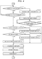
- FIGS. 3 and 4 are flowcharts illustrating information processing by the processor 1.
- the information processing described below is exemplary and a change in a procedure of some processes, omission of some processes, or addition of other processes can be appropriately made.
- the processor 1 performs an initialization process such as clearing of a commodity list.
- the commodity list is a list of sales commodities of one commercial transaction target and is stored in the main storage unit 2 or the auxiliary storage unit 3.
- the commodity list includes a commodity code for identifying at least each of the sales commodities.
- the commodity list may include data such as a commodity name, a unit price, and the like of each of the sales commodities.
- the processor 1 displays a registration screen on the display device 5.
- the registration screen is a screen for an operation of registering sales commodities.
- FIG. 5 is a diagram illustrating an example of a form of a registration screen SC1.
- the registration screen SC1 shows a button group BG1 and areas AR1 and AR2.
- the button group BG1 includes 15 buttons. Each function can be allocated in advance to each button included in the button group BG1.
- the button group BG1 may include any number of buttons and any function can be allocated to each button, or a designer, a manager, or the like of the checkout device 100 may appropriately decide the number of buttons and a function allocated to each button.
- one button located at the right corner among the buttons included in the button group BG1 is allocated as a button for instructing to proceed to registration finishing and payment.
- Other buttons of the button group BG1 are allocated to buttons for designating a commodity registered as a sales commodity.
- the area AR1 shows a commodity name, a number, and a unit price of a sales commodity designated most recently.
- a text string of "COMMODITY G,” “1 PIECE(S),” and “128 YEN” indicates a commodity name, a number, and a unit price, respectively.
- the area AR2 shows a total number and a total amount of registered sales commodities. For example, a text string of "6 PIECE(S)" and "1,363 YEN" indicates a total number and a total amount.
- FIG. 5 to facilitate understanding information shown in the areas AR1 and AR2, it is indicated how many sales commodities are registered. However, the processor 1 does not show the text strings indicating the foregoing information regarding the sales commodities in the areas AR1 and AR2 in Act2.
- the processor 1 checks whether the registered sales commodities are designated. Then, when the commodities are not designated, the processor 1 determines that the result is no, and then the process proceeds to Act4. In Act4, the processor 1 checks whether payment is instructed. Then, when the payment is not instructed, the processor 1 determines that the result is no, and then the process returns to Act3. Thus, the processor 1 waits until the commodity is designated or the payment is instructed in Act3 and Act4.
- the shopper picks up the purchased commodities purchased by the shopper from a sales area and brings the commodities to a checkout corner.
- the shopper stands before the checkout device 100 installed in the checkout corner and performs a registration operation of registering the sales commodities.
- the registration operation is an operation of causing the fixed scanner 7 to read barcodes displayed on the sales commodities, an operation of causing the handy scanner 8 to read the barcodes, an operation of touching the buttons to which the sales commodities are allocated on the registration screen SC1, or the like.
- the fixed scanner 7 has a function of identifying commodities using an object recognition technology based on features of images of the commodities, an operation of causing the fixed scanner 7 to image commodities such as fruits and vegetables to which barcodes are not attached is also included in the registration operation.
- the processor 1 determines in Act3 that the result is yes, and then the process proceeds to Act5. In Act5, the processor 1 updates the commodity list so that the designated commodities are shown as the sales commodities. The processor 1 adds, for example, the commodities codes of the designated commodities to the commodity list.
- the processor 1 updates the registration screen displayed on the display device 5.
- the processor 1 updates display of the areas AR1 and AR2 of the registration screen so that content of the commodity list updated as described above is reflected.
- the processor 1 subsequently returns to the waiting state of Act3 and Act4. Accordingly, when the processor 1 performs the information processing based on the information processing program, the computer in which the processor 1 is a central unit functions as a registration unit that registers the sales commodities.
- the shopper When the shopper finishes shopping and finishes the registration of all the sales commodities, the shopper performs an operation decided in advance to instruction payment. For example, the shopper touches the buttons included in the button group BG1 on the registration screen SC1 to give an instruction to move to payment. When the touch sensor 6 detects the touches of the buttons, the processor 1 determines in Act4 that the result is yes, and then the process proceeds to Act7.
- the processor 1 calculates a payment price of all the sales commodities for selling. As a specific process of calculating the payment price, a similar process to a process performed in the same kind of another checkout device can be applied.
- the processor 1 selects one of a plurality of method selection screens prepared in advance in accordance with content of a transaction.
- the method selection screen is a screen on which the shopper selects a payment method.
- a first method selection screen and a second method selection screen are assumed to be prepared.
- FIG. 6 is a diagram illustrating a first method selection screen SC2.
- the first method selection screen SC2 shows buttons BU1 and BU2 and guidance images GI1, GI2, and GI3.
- dotted lines indicate positions of the antennas 14a, 14b, and 14c and are not shown on the first method selection screen SC2.
- the button BU1 is a button for selecting payment in cash.
- the button BU2 is a button for selecting payment by credit.
- the guidance images GI1, GI2, and GI3 are images for guiding regions which IC tags approach when electronic money payment is used.
- the guidance images GI1, GI2, and GI3 correspond to the antennas 14a, 14b, and 14c, respectively, and display positions of the guidance images GI1, GI2, and GI3 on the first method selection screen SC2 are decided to face the corresponding antennas.
- the guidance images GI1, GI2, and GI3 show frame lines indicating the regions to which the IC tags approach and text messages.
- the text message informs the shopper where the IC tag approaches when a certain payment service is used.
- the method selection screen illustrated in FIG. 6 is a screen in which a payment service which is "Service A" is associated with the antenna 14a. Therefore, the text message shown in the guidance image GI1 informs the shopper that the IC tag has to approach the guidance image GI1 when the payment service which is "Service A” is used as "TOUCH HERE FOR SERVICE A.”
- the first method selection screen is equivalent to a screen that shows an image in which a payment service associated with the corresponding antenna can be identified in each of the plurality of regions corresponding to the plurality of antennas on the display surface of the display device 5. Accordingly, when the processor 1 performs the information processing based on the information processing program, the computer in which the processor 1 is a central unit functions as a control unit that controls the display devices such that the screen is displayed.
- FIG. 7 is a diagram illustrating a second method selection screen SC3.
- the second method selection screen SC3 shows buttons BU1 and BU21 and guidance images GI1, GI21, and GI31.
- the second method selection screen SC3 shows the buttons BU21 and the guidance images GI21 and GI31 instead of the button BU2 and the guidance images GI2 and GI3 on the first method selection screen SC2.
- frame lines of the button BU21 and the guidance images GI21 and GI31 are indicated by dotted lines, and this represents to be unavailable by gray-out display.
- the processor 1 selects the second method selection screen SC3 when commodities for which only cash payment or electronic money payment is permitted in Service A are included in sale commodities, and selects the first method selection screen SC2 in other cases.
- a method selection screen adapted thereto is prepared. Three or more method selection screens may be prepared.
- the processor 1 displays the method selection screen selected in this way on the display device 5.
- the processor 1 instructs the switcher 13 to start scanning by the antennas 14a, 14b, and 14c. At this time, the processor 1 instructs the switcher 13 to select a scanning pattern decided in advance in association with the method selection screen selected in Act8. For a scanning pattern corresponding to the first method selection screen, for example, the antennas 14a, 14b, and 14c are selected in this order. For a scanning pattern corresponding to the second method selection screen, for example, only the antenna 14a is selected normally. The designer, the manager, or the like of the checkout device 100 may appropriately decide the scanning pattern.
- the switcher 13 connects one of the antennas 14a, 14b, and 14c to the proximity communication unit 12 in the designated scanning pattern.
- the processor 1 checks whether the payment method is designated. Then, when the payment method is not designated, the processor 1 determines that the result is no, and then the process proceeds to Act12. In Act12, the processor 1 checks whether the proximity communication unit 12 enters a state in which the proximity communication unit 12 can communicate with the IC tag. Then, when the proximity communication unit 12 cannot communicate, the processor 1 determines that the result is no, and then the process returns to Act11. Accordingly, the processor 1 waits until the payment method is designated or the proximity communication unit 12 can communicate in Act 11 and Act12.
- the shopper touches the button BU1 or the button BU2 to designate the cash payment or the credit payment.
- the processor 1 determines in Act11 that the result is yes, and then the process proceeds to Act13.
- the processor 1 decides the designated payment method as a payment method to be used.
- the processor 1 displays the payment screen in accordance with the decided payment method on the display device 5.
- the payment screen is a screen for prompting a shopper to perform a payment operation in accordance with the payment method.
- a payment screen by the cash payment is a screen for prompting a shopper to input cash into the automatic change machine 10.
- a payment screen by the credit payment is a screen for prompting a shopper to cause the card reader 11 to read a credit card.
- the processor 1 waits until the payment operation is performed. Then, when the cash is input to the automatic machine 10 or the credit card is read in the card reader 11, the processor 1 determines that the result is yes, and then the process proceeds to Act21.
- an IC chip on which electronic money data for the payment service to be used is recorded is held to the display surface of the display device 5 so that the IC chip approaches a guidance image in accordance with the payment service.
- an IC chip corresponding to the payment service A is held to the display surface of the display device 5 so that the IC chip approaches the guidance image GI1.
- the proximity communication unit 12 enters a state of communication with the IC tag.
- the proximity communication unit 12 instructs the switcher 13 to stop scanning.
- the switcher 13 keeps selecting the antenna selected at that time.
- the proximity communication unit 12 reads electronic money data recorded on the IC tag from the IC tag through wireless communication.
- the electronic money data represents an identification code, a balance, and the like of electronic money.
- the IC tag records the electronic money data related to a plurality of payment services in some cases. Accordingly, the proximity communication unit 12 reads the electronic money data related to a payment service associated with the antenna selected by the switcher 13 from the IC tag. This process may be performed autonomously by the proximity communication unit 12 or under the control of the processor 1.
- the processor 1 determines in Act12 that the result is yes, the process proceeds to Act16.
- the processor 1 checks whether the switcher 13 selects a first antenna. Then, when the switcher 13 selects an antenna decided in advance as the first antenna among the antennas 14a, 14b, and 14c, the processor 1 determines that the result is yes, and then the process proceeds to Act17.
- the processor 1 decides electronic money payment by a first payment service as the payment method to be used.
- the first payment service is a payment service associated with the first antenna.
- the first antenna is the antenna 14a and the payment service which is "Service A" is associated with the antenna 14a, as described above, the first payment service is a payment service which is "Service A.” Thereafter, the processor 1 causes the process to proceed to Act21.
- the processor 1 checks whether the switcher 13 selects the second antenna. Then, when the switcher 13 selects an antenna decided in advance as the second antenna among the antennas 14a, 14b, and 14c, the processor 1 determines that the result is yes, and then the process proceeds to Act19. In Act19, the processor 1 decides electronic money payment by the second payment service as the payment method to be used.
- the second payment service is a payment service associated with the second antenna.
- the second payment service is a payment service which is "Service B" is associated with the antenna 14b
- the second payment service is a payment service which is "Service B.” Thereafter, the processor 1 causes the process to proceed to Act21.
- the processor 1 determines in Act18 that the result is no, and then the process proceeds to Act20.
- the processor 1 decides electronic money payment by the third payment service as the payment method to be used.
- the third payment service is a payment service associated with the third antenna.
- the third antenna is the antenna 14c and the payment service which is "Service C" is associated with the antenna 14c, the third payment service is a payment service which is "Service C.” Thereafter, the processor 1 causes the process to proceed to Act21.
- the processor 1 causes the process from Act15, Act17, Act19, or Act20 to proceed to Act21.
- the processor 1 acquires payment data for the payment process in accordance with the decided payment method.
- the payment data is data or the like of an input price counted by the automatic change machine 10.
- the payment data is credit data or the like read by the card reader 11 from a credit card.
- the payment data is electronic money data or the like read by the proximity communication unit 12.
- the processor 1 performs a payment process of paying the payment price calculated in Act7 using the payment method decided in Act13, Act17, Act19, or Act20.
- the processor 1 uses the payment data acquired in Act21 in the payment process.
- a similar process to a process performed by the same kind of another checkout device can be applied to the payment process.
- the processor 1 when wireless communication for the payment process starts via one of the antennas 14a, 14b, and 14c, the processor 1 performs the payment process of payment in which a payment service associated with the antenna is used. That is, when the processor 1 performs the information processing based on the information processing program, the computer in which the processor 1 is a central unit functions as a payment unit that performs the payment process in this way.
- the processor 1 operates the printer 9 to issue a receipt.
- the series of processes related to one transaction is completed. Accordingly, the processor 1 returns the process to Act1 of FIG. 3 and prepares for starting a process related to a next transaction.
- a shopper who tries to make payment using electronic money may approach an IC tag to an antenna associated with a payment service to be used among the antennas 14a, 14b, and 14c. That is, the shopper can make electronic money payment by a desired payment service without designating a payment service, for example, operating a button. Therefore, it is possible to reduce trouble of a shopper who is the operator.
- a shopper can approach an IC tag to an antenna associated to a payment service to be used when the shopper approaches the IC tag to one of the guidance images GI1, GI2, and GI3 in accordance with a guidance in the guidance images GI1, GI2, and GI3 shown on the first method selection screen SC2. Since work of the shopper at this time is an approach of the IC tag to the display surface of the display device 5 in accordance with display on the display device 5, this work is intuitive work. Thus, it is possible to further reduce the trouble of the shopper.
- an operation of registering sales commodities is also received through a touch operation on the display surface of the display device 5.
- one of the work and work for selecting a payment service can also be performed on the display surface of the display device 5.
- the antennas 14a, 14b, and 14c are disposed to be superimposed on the display surface of the display device 5. Therefore, a separate distance between the antenna and the IC tag approached to the display surface is shorter than when the antennas 14a, 14b, and 14c are disposed on the rear surface side of the display device 5. Therefore, a communication environment between the IC tag and one of the antennas 14a, 14b, and 14c can be satisfactory and a possibility of reliable communication being performed can be high.
- a method selection screen on which the guidance image GI1 related to a service permitted to be used is available is displayed as in the second method selection screen SC3. Therefore, a shopper can easily approach the IC tag to the antenna associated with an available payment service.
- the embodiment can be modified in various forms as follows.
- the checkout device 100 is adapted to a process of selling commodities in a sales store and can also be realized as a sales processing device of a different form such as a vending machine, a ticket machine, an advance payment food ordering machine, etc.
- the checkout device 100 performs each process of the registration, the calculation of a payment price, and the payment, but can also be realized as an accounting device that calculates and pays a payment price based on a registration result in another device without performing the registration or the registration and the calculation of the payment price or a payment device that pays a payment prices calculated in another device.
- the antennas 14a, 14b, and 14c may be disposed on the rear surface side of the display device 5. Alternatively, the antennas 14a, 14b, and 14c may be disposed so that the antennas 14a, 14b, and 14c are not superimposed on the display device 5.
- any one of the antennas 14a, 14b, and 14c may not be provided. Alternatively, one or more antennas may be additionally provided in addition to the antennas 14a, 14b, and 14c.
- a plurality of proximity communication units 12 may be provided.
- the same number of proximity communication units 12 as the number of antennas may be provided and each of the antennas may be connected to each of the proximity communication units 12.
- the processor 1 may decide a payment service to be used in accordance with a state in which any of the plurality of proximity communication units 12 can communicate with the IC tag.
- a plurality of proximity communication units 12 less than the number of antennas may be provided and each antenna may be connected to any of the plurality of proximity communication units 12.
- the processor 1 may decide a payment service to be used in accordance with whether any of the plurality of proximity communication units 12 communicates with the IC tag via a certain antenna.
- Some or all of the functions realized by the processor 1 through the information processing can also be realized by hardware such as a logic circuit that performs information processing which is not based on a program.
- the foregoing functions can also be realized by combining software control with the hardware such as the logic circuit.
Landscapes
- Engineering & Computer Science (AREA)
- Theoretical Computer Science (AREA)
- Physics & Mathematics (AREA)
- Business, Economics & Management (AREA)
- General Physics & Mathematics (AREA)
- General Engineering & Computer Science (AREA)
- Accounting & Taxation (AREA)
- Human Computer Interaction (AREA)
- Computer Hardware Design (AREA)
- Computer Networks & Wireless Communication (AREA)
- Strategic Management (AREA)
- General Business, Economics & Management (AREA)
- Finance (AREA)
- Signal Processing (AREA)
- Toxicology (AREA)
- Health & Medical Sciences (AREA)
- Economics (AREA)
- Development Economics (AREA)
- Microelectronics & Electronic Packaging (AREA)
- Electromagnetism (AREA)
- General Health & Medical Sciences (AREA)
- Artificial Intelligence (AREA)
- Computer Vision & Pattern Recognition (AREA)
- Cash Registers Or Receiving Machines (AREA)
- Control Of Vending Devices And Auxiliary Devices For Vending Devices (AREA)
Abstract
Description
- Embodiments described herein relate generally to a payment device and a sales processing device.
- There is a plurality of types of contactless electronic money payment services in which common communication schemes are used. Therefore, in a payment device and a sales processing device corresponding to electronic money payment, in the related art, it is necessary to recognize which electronic money payment service is used before payment data stored in a storage medium is acquired through contactless communication. Therefore, an operator designates a service. That is, when an electronic money service is used, an operator takes trouble to perform an operation of designating one service among a plurality of types of payment services. In view of such circumstances, it is desirable to reduce the trouble of the operation by the operator.
- To solve such problem, there is provided a payment device comprising:
- a plurality of antennas; and
- a payment unit configured to perform a payment process for payment in which a payment service associated with a respective one of the plurality of antennas is used in accordance with start of wireless communication for the payment process via the respective one of the plurality of antennas.
- Preferably, the payment device further comprises a display device having a display surface, wherein each of the plurality of antennas is disposed variously along the display surface.
- Preferably still, the payment device further comprises a touch sensor disposed along the display surface and over the plurality of antennas.
- Preferably yet, the touch sensor and the plurality of antennas are transparent such that a display provided by the display device is visible through the antennas and the touch sensor.
- Suitably, the payment device further comprises:
- a communication unit configured to perform wireless communication with an external device via the plurality of antennas; and
- a switching unit configured to switch between the plurality of antennas connected to the communication unit in response to the communication unit failing to perform the wireless communication with the external device via a currently active one of the plurality of antennas.
- Suitably still, the external device is an integrated circuit tag.
- The invention also relates to a payment device comprising:
- a display device;
- a plurality of antennas superimposed on the display device and mutually disposed along a display surface of the display device;
- a control unit configured to control the display device such that a screen indicating an image for identifying a payment service associated with the corresponding antenna is displayed in each of a plurality of regions corresponding to each of the plurality of antennas on the display surface when the payment service to be used is selected from a plurality of payment services; and
- a payment unit configured to perform a payment process for payment by using the payment service associated with a respective one of the plurality of antennas in accordance with start of wireless communication for the payment process via the respective one of the plurality of antennas.
- Preferably, the payment device further comprises a touch sensor superimposed on the display surface of the display device and configured to detect a touch position, wherein the plurality of antennas is disposed between the touch sensor and the display surface of the display device.
- Preferably still, the control unit controls the display device such that an image for identifying one or more payment services permitted to be used with regard to a transaction are shown as available.
- Preferably yet, the payment device further comprises:
- a communication unit configured to perform wireless communication with an external device via the plurality of antennas; and
- a switching unit configured to switch between the plurality of antennas connected to the communication unit in response to the communication unit failing to perform the wireless communication with the external device via a currently active one of the plurality of antennas;
- wherein the payment unit performs the payment process for payment in which a payment service associated with the antenna connected to the communication unit by the switching unit is used when the communication unit starts the wireless communication.
- The invention also concerns a sales processing device comprising:
- a registration unit configured to register a sales commodity;
- a display device;
- a plurality of antennas superimposed on the display device and mutually disposed along a display surface of the display device;
- a control unit configured to control the display device such that a first screen for an operation of registering the sales commodity is displayed when the registration unit registers the sales commodity, and a second screen indicating an image for identifying a payment service associated with each of the plurality of antennas is displayed in each of a plurality of regions corresponding to the plurality of antennas on the display surface when the payment service to be used is selected from a plurality of payment services; and
- a payment unit configured to perform a payment process of paying a payment price with regard to sales of a commodity registered as the sales commodity by the registration unit by using the payment service associated with a respective one of the plurality of antennas in accordance with start of wireless communication for the payment process via the respective one of the plurality of antennas.
- The invention further relates to a sales processing method comprising the steps of:
- registering a sales commodity;
- displaying a first screen, on a display device, for an operation of registering the sales commodity is displayed when registering the sales commodity;
- displaying a second screen, on the display device, indicating an image for identifying a payment service associated with each of a plurality of antennas is displayed in each of a plurality of regions corresponding to the plurality of antennas on the display surface when the payment service to be used is selected from a plurality of payment services, the plurality of antennas being superimposed on the display device and mutually disposed along a display surface of the display device; and
- performing a payment process of paying a payment price with regard to sales of a commodity registered as the sales commodity by the registering step by using the payment service associated with a respective one of the plurality of antennas in accordance with start of wireless communication for the payment process via the respective one of the plurality of antennas.
- The invention further concerns a computer program comprising instructions which, when the program is executed by a computer, cause the computer to carry out the steps of the method above.
- The invention also relates to a computer-readable medium having stored thereon the computer program above.
- The above and other objects, features and advantages of the present invention will be made apparent from the following description of the preferred embodiments, given as non-limiting examples, with reference to the accompanying drawings, in which:
-
FIG. 1 is a block diagram illustrating a main unit circuit configuration of a checkout device according to an embodiment; -
FIG. 2 is a diagram schematically illustrating disposition of antennas inFIG. 1 ; -
FIG. 3 is a flowchart illustrating information processing by a processor inFIG. 1 ; -
FIG. 4 is a flowchart illustrating the information processing; -
FIG. 5 is a diagram illustrating an example of a form of a registration screen; -
FIG. 6 is a diagram illustrating a first method selection screen; and -
FIG. 7 is a diagram illustrating a second method selection screen. - Embodiments provide a payment device and a sales processing device capable of reducing trouble of an operation by an operator.
- In general, according to one embodiment, a payment device includes a plurality of antennas and a payment unit. The payment unit performs a payment process for payment in which a payment service associated with one antenna is used in accordance with start of wireless communication for the payment process via the one antenna among the plurality of antennas.
- Hereinafter, an example of an embodiment will be described with reference to the drawings. In the embodiment, an example of a checkout device that has functions of a commodity registration device registering sales commodities and a payment device performing a process of paying prices of the registered sales commodities will be described.
-
FIG. 1 is a block diagram illustrating a main unit circuit configuration of acheckout device 100 according to the embodiment. Thecheckout device 100 according to the embodiment is also called a self-checkout device, a self-checkout type of point-of-sales (POS) terminal, or a self-registration device. Thecheckout device 100 is mainly operated by a shopper. Accordingly, the shopper is an operator of thecheckout device 100. Here, a store clerk can also be an operator of thecheckout device 100. - The
checkout device 100 includes aprocessor 1, amain storage unit 2, anauxiliary storage unit 3, ameasuring unit 4, adisplay device 5, atouch sensor 6, a fixed scanner 7, ahandy scanner 8, aprinter 9, anautomatic change machine 10, acard reader 11, aproximity communication unit 12, aswitcher 13,antennas communication unit 15, and atransmission path 16. Theprocessor 1, themain storage unit 2, and theauxiliary storage unit 3 are connected by thetransmission path 16 to configure a computer that performs information processing to realize various functions of thecheckout device 100. - The
processor 1 is equivalent to a central unit of the computer. Theprocessor 1 performs information processing to realize various functions of thecheckout device 100 in accordance with an information processing program such as an operating system, middleware, and an application program. Theprocessor 1 is, for example, a central processing unit (CPU). - The
main storage unit 2 is equivalent to a main storage unit of the computer. Themain storage unit 2 includes a nonvolatile memory region and a volatile memory region. Themain storage unit 2 stores at least a part of the information processing program in the nonvolatile memory region. Themain storage unit 2 stores data necessary for theprocessor 1 to perform a process of controlling each unit in the nonvolatile or volatile memory region in some cases. Themain storage unit 2 uses a volatile memory region as a work area in which theprocessor 1 can appropriate rewrite data. The nonvolatile memory region is, for example, a read-only memory (ROM). The volatile memory region is, for example, a random access memory (RAM). - The
auxiliary storage unit 3 is equivalent to an auxiliary storage unit of the computer. For example, an electric erasable programmable read-only memory (EEPROM), a hard disk drive (HDD), or a solid-state drive (SSD) is used as theauxiliary storage unit 3. Theauxiliary storage unit 3 stores data used for theprocessor 1 to perform various processes or data generated through a process by theprocessor 1. Theauxiliary storage unit 3 stores a part of the information processing program in some cases. - The measuring
unit 4 measures the weight of a registered commodity. Thedisplay device 5 displays various screens for informing an operator of various kinds of information on a display surface. Some of the various screens configure a graphical user interface (GUI). For example, a liquid crystal panel or the like is used as thedisplay device 5. Thetouch sensor 6 is superimposed on the display surface of thedisplay device 5 and detects a touch position when a touch operation on the display surface is performed. Thus, thetouch sensor 6 receives a touch operation for operating the GUI. - The fixed scanner 7 images a held commodity and then identifies a barcode displayed on the commodity through image processing. Then, the fixed scanner 7 outputs information indicating the identified barcode to the
processor 1. As the fixed scanner 7, another type of known device that identifies a barcode using reflection of laser light can be used. The fixed scanner 7 may have a function of identifying a commodity using an object recognition technology based on a feature of an image of the commodity. - The
handy scanner 8 is generally carried and used by the operator. Thehandy scanner 8 reads a barcode displayed on a commodity and outputs information represented by the barcode to theprocessor 1. - The
printer 9 includes a receipt printer and a journal printer. The receipt printer issues various certificates by printing various kinds of information on a receipt sheet. The various certificates are receipts or the like representing content or the like of a commercial transaction. The journal printer prints journal data including information printed on a receipt sheet by the receipt printer on a journal sheet. The journal sheet is retained inside thecheckout device 100 as long as a maintenance person is not taken out the journal sheet. The journal data may be stored in theauxiliary storage unit 3 in association with a transaction code for identifying an individual transaction and may be printed on a receipt sheet by the receipt printer as necessary. In this case, it is not necessary to include the journal printer in theprinter 9. - The
automatic change machine 10 receives input coins and paper money. Theautomatic change machine 10 discharges coins and paper money as change. Thecard reader 11 reads credit data recorded on a credit card and outputs the data to theprocessor 1. The credit data represents a credit card number, a holder name, an expiration period, a card brand, and the like. - The
proximity communication unit 12 performs proximity wireless communication with an integrated circuit (IC) tag for electronic money payment via any of theantennas proximity communication unit 12 is an example of a communication unit. Theswitcher 13 switches connection of the antenna to theproximity communication unit 12 among theantennas switcher 13 is an example of a switching unit. Theantennas proximity communication unit 12 to perform proximity wireless communication with an IC tag. Separate payment services provided by different electronic money payment service providers are associated in advance with theantennas antennas checkout device 100 may decide the association. - The
communication unit 15 performs data communication with a device (not illustrated) connected to a communication network (not illustrated) in conformity with a predetermined communication protocol. A local area network (LAN) is generally used as the communication network. However, as the communication network, the Internet, a virtual private network (VPN), a public communication network, a mobile communication network, and the like can be appropriately used in combination with or independent of the LAN. A known device in conformity with a communication scheme of the communication network can be used as thecommunication unit 15. A partner device with which thecommunication unit 15 performs the data communication is, for example, a POS server or the like. Thetransmission path 16 includes an address bus, a data bus, and a control signal line and transmits data and a control signal exchanged with each of the connected units. -
FIG. 2 is a diagram schematically illustrating disposition ofantennas FIG. 2 , the same reference numerals are given to the same elements illustrated inFIG. 1 . Theantennas display device 5 at postures in which a direction intersecting the display surface is an orientation direction. Theantennas display device 5. Theantennas display device 5. Thetouch sensor 6 is disposed over thedisplay device 5 and theantennas touch sensor 6 is also transparent and transmits a screen displayed on thedisplay device 5. Thus, the display screen on thedisplay device 5 can be viewed through thetouch sensor 6 and theantennas display device 5 and thetouch sensor 6 configure a touch panel with theantennas - Next, an operation of the
checkout device 100 that has the above-described configuration will be described. Theprocessor 1 performs information processing to be described below when thecheckout device 100 is set to an operation mode in which a process of checking out shopping of a shopper is performed in response to an operation by the shopper. - The
main storage unit 2 or theauxiliary storage unit 3 stores an information processing program that describes information processing to be described below. The information processing program may be stored in themain storage unit 2 or theauxiliary storage unit 3 in hardware transfer of thecheckout device 100 or may be transferred separately from the hardware. In the latter case, the information processing program may be recorded on a removable recording medium such as a magnetic disk, a magneto-optical disc, an optical disc, or a semiconductor memory or may be transferred via a network. In the latter case, for example, the information processing program is supplied as a version-updated program and is written on theauxiliary storage unit 3 by theprocessor 1 in accordance with an artificial operation. The information processing program is substituted with the same kind of another information processing program stored in advance in themain storage unit 2 or theauxiliary storage unit 3. -
FIGS. 3 and4 are flowcharts illustrating information processing by theprocessor 1. The information processing described below is exemplary and a change in a procedure of some processes, omission of some processes, or addition of other processes can be appropriately made. - In Act1, the
processor 1 performs an initialization process such as clearing of a commodity list. The commodity list is a list of sales commodities of one commercial transaction target and is stored in themain storage unit 2 or theauxiliary storage unit 3. The commodity list includes a commodity code for identifying at least each of the sales commodities. The commodity list may include data such as a commodity name, a unit price, and the like of each of the sales commodities. In Act2, theprocessor 1 displays a registration screen on thedisplay device 5. The registration screen is a screen for an operation of registering sales commodities. -
FIG. 5 is a diagram illustrating an example of a form of a registration screen SC1. The registration screen SC1 shows a button group BG1 and areas AR1 and AR2. The button group BG1 includes 15 buttons. Each function can be allocated in advance to each button included in the button group BG1. The button group BG1 may include any number of buttons and any function can be allocated to each button, or a designer, a manager, or the like of thecheckout device 100 may appropriately decide the number of buttons and a function allocated to each button. In the example ofFIG. 5 , one button located at the right corner among the buttons included in the button group BG1 is allocated as a button for instructing to proceed to registration finishing and payment. Other buttons of the button group BG1 are allocated to buttons for designating a commodity registered as a sales commodity. - The area AR1 shows a commodity name, a number, and a unit price of a sales commodity designated most recently. A text string of "COMMODITY G," "1 PIECE(S)," and "128 YEN" indicates a commodity name, a number, and a unit price, respectively. The area AR2 shows a total number and a total amount of registered sales commodities. For example, a text string of "6 PIECE(S)" and "1,363 YEN" indicates a total number and a total amount. In
FIG. 5 , to facilitate understanding information shown in the areas AR1 and AR2, it is indicated how many sales commodities are registered. However, theprocessor 1 does not show the text strings indicating the foregoing information regarding the sales commodities in the areas AR1 and AR2 in Act2. - In Act3, the
processor 1 checks whether the registered sales commodities are designated. Then, when the commodities are not designated, theprocessor 1 determines that the result is no, and then the process proceeds to Act4. In Act4, theprocessor 1 checks whether payment is instructed. Then, when the payment is not instructed, theprocessor 1 determines that the result is no, and then the process returns to Act3. Thus, theprocessor 1 waits until the commodity is designated or the payment is instructed in Act3 and Act4. - The shopper picks up the purchased commodities purchased by the shopper from a sales area and brings the commodities to a checkout corner. The shopper stands before the
checkout device 100 installed in the checkout corner and performs a registration operation of registering the sales commodities. The registration operation is an operation of causing the fixed scanner 7 to read barcodes displayed on the sales commodities, an operation of causing thehandy scanner 8 to read the barcodes, an operation of touching the buttons to which the sales commodities are allocated on the registration screen SC1, or the like. When the fixed scanner 7 has a function of identifying commodities using an object recognition technology based on features of images of the commodities, an operation of causing the fixed scanner 7 to image commodities such as fruits and vegetables to which barcodes are not attached is also included in the registration operation. - When one of the registration processes is performed, the
processor 1 determines in Act3 that the result is yes, and then the process proceeds to Act5. In Act5, theprocessor 1 updates the commodity list so that the designated commodities are shown as the sales commodities. Theprocessor 1 adds, for example, the commodities codes of the designated commodities to the commodity list. - In Act6, the
processor 1 updates the registration screen displayed on thedisplay device 5. Theprocessor 1 updates display of the areas AR1 and AR2 of the registration screen so that content of the commodity list updated as described above is reflected. Then, theprocessor 1 subsequently returns to the waiting state of Act3 and Act4. Accordingly, when theprocessor 1 performs the information processing based on the information processing program, the computer in which theprocessor 1 is a central unit functions as a registration unit that registers the sales commodities. - When the shopper finishes shopping and finishes the registration of all the sales commodities, the shopper performs an operation decided in advance to instruction payment. For example, the shopper touches the buttons included in the button group BG1 on the registration screen SC1 to give an instruction to move to payment. When the
touch sensor 6 detects the touches of the buttons, theprocessor 1 determines in Act4 that the result is yes, and then the process proceeds to Act7. - In Act7, the
processor 1 calculates a payment price of all the sales commodities for selling. As a specific process of calculating the payment price, a similar process to a process performed in the same kind of another checkout device can be applied. - In Act8, the
processor 1 selects one of a plurality of method selection screens prepared in advance in accordance with content of a transaction. The method selection screen is a screen on which the shopper selects a payment method. In the embodiment, a first method selection screen and a second method selection screen are assumed to be prepared. -
FIG. 6 is a diagram illustrating a first method selection screen SC2. The first method selection screen SC2 shows buttons BU1 and BU2 and guidance images GI1, GI2, and GI3. InFIG. 6 , dotted lines indicate positions of theantennas - The button BU1 is a button for selecting payment in cash. The button BU2 is a button for selecting payment by credit. The guidance images GI1, GI2, and GI3 are images for guiding regions which IC tags approach when electronic money payment is used. The guidance images GI1, GI2, and GI3 correspond to the
antennas FIG. 6 is a screen in which a payment service which is "Service A" is associated with theantenna 14a. Therefore, the text message shown in the guidance image GI1 informs the shopper that the IC tag has to approach the guidance image GI1 when the payment service which is "Service A" is used as "TOUCH HERE FOR SERVICE A." - Accordingly, the first method selection screen is equivalent to a screen that shows an image in which a payment service associated with the corresponding antenna can be identified in each of the plurality of regions corresponding to the plurality of antennas on the display surface of the
display device 5. Accordingly, when theprocessor 1 performs the information processing based on the information processing program, the computer in which theprocessor 1 is a central unit functions as a control unit that controls the display devices such that the screen is displayed. -
FIG. 7 is a diagram illustrating a second method selection screen SC3. InFIG. 7 , the same reference numerals are given to the same display elements as those illustrated inFIG. 6 and the detailed description thereof will not be repeated. The second method selection screen SC3 shows buttons BU1 and BU21 and guidance images GI1, GI21, and GI31. The second method selection screen SC3 shows the buttons BU21 and the guidance images GI21 and GI31 instead of the button BU2 and the guidance images GI2 and GI3 on the first method selection screen SC2. InFIG. 7 , frame lines of the button BU21 and the guidance images GI21 and GI31 are indicated by dotted lines, and this represents to be unavailable by gray-out display. - The
processor 1 selects the second method selection screen SC3 when commodities for which only cash payment or electronic money payment is permitted in Service A are included in sale commodities, and selects the first method selection screen SC2 in other cases. When commodities for which combinations of permitted payment methods are different are considered to be sales commodities, a method selection screen adapted thereto is prepared. Three or more method selection screens may be prepared. In Act9, theprocessor 1 displays the method selection screen selected in this way on thedisplay device 5. - In Act10, the
processor 1 instructs theswitcher 13 to start scanning by theantennas processor 1 instructs theswitcher 13 to select a scanning pattern decided in advance in association with the method selection screen selected in Act8. For a scanning pattern corresponding to the first method selection screen, for example, theantennas antenna 14a is selected normally. The designer, the manager, or the like of thecheckout device 100 may appropriately decide the scanning pattern. Theswitcher 13 connects one of theantennas proximity communication unit 12 in the designated scanning pattern. - In Act11 of
FIG. 4 , theprocessor 1 checks whether the payment method is designated. Then, when the payment method is not designated, theprocessor 1 determines that the result is no, and then the process proceeds to Act12. In Act12, theprocessor 1 checks whether theproximity communication unit 12 enters a state in which theproximity communication unit 12 can communicate with the IC tag. Then, when theproximity communication unit 12 cannot communicate, theprocessor 1 determines that the result is no, and then the process returns to Act11. Accordingly, theprocessor 1 waits until the payment method is designated or theproximity communication unit 12 can communicate inAct 11 and Act12. - When payment using cash or a credit is desired, the shopper touches the button BU1 or the button BU2 to designate the cash payment or the credit payment. When the
touch sensor 6 detects such a button touch, theprocessor 1 determines in Act11 that the result is yes, and then the process proceeds to Act13. In Act13, theprocessor 1 decides the designated payment method as a payment method to be used. - In Act14, the
processor 1 displays the payment screen in accordance with the decided payment method on thedisplay device 5. The payment screen is a screen for prompting a shopper to perform a payment operation in accordance with the payment method. For example, a payment screen by the cash payment is a screen for prompting a shopper to input cash into theautomatic change machine 10. For example, a payment screen by the credit payment is a screen for prompting a shopper to cause thecard reader 11 to read a credit card. In Act15, theprocessor 1 waits until the payment operation is performed. Then, when the cash is input to theautomatic machine 10 or the credit card is read in thecard reader 11, theprocessor 1 determines that the result is yes, and then the process proceeds to Act21. - When the shopper desires payment using electronic money, an IC chip on which electronic money data for the payment service to be used is recorded is held to the display surface of the
display device 5 so that the IC chip approaches a guidance image in accordance with the payment service. For example, when the electronic money payment in accordance with the payment service A is used, an IC chip corresponding to the payment service A is held to the display surface of thedisplay device 5 so that the IC chip approaches the guidance image GI1. - Then, when the IC chip is located within a sensitivity range of an antenna facing a guidance image which the IC tag approaches among the
antennas switcher 13 selects this antenna, theproximity communication unit 12 enters a state of communication with the IC tag. In this case, theproximity communication unit 12 instructs theswitcher 13 to stop scanning. After the instruction, theswitcher 13 keeps selecting the antenna selected at that time. Thereafter, theproximity communication unit 12 reads electronic money data recorded on the IC tag from the IC tag through wireless communication. The electronic money data represents an identification code, a balance, and the like of electronic money. The IC tag records the electronic money data related to a plurality of payment services in some cases. Accordingly, theproximity communication unit 12 reads the electronic money data related to a payment service associated with the antenna selected by theswitcher 13 from the IC tag. This process may be performed autonomously by theproximity communication unit 12 or under the control of theprocessor 1. - When the communication is possible in this way, the
processor 1 determines in Act12 that the result is yes, the process proceeds to Act16. In Act16, theprocessor 1 checks whether theswitcher 13 selects a first antenna. Then, when theswitcher 13 selects an antenna decided in advance as the first antenna among theantennas processor 1 determines that the result is yes, and then the process proceeds to Act17. In Act17, theprocessor 1 decides electronic money payment by a first payment service as the payment method to be used. The first payment service is a payment service associated with the first antenna. When the first antenna is theantenna 14a and the payment service which is "Service A" is associated with theantenna 14a, as described above, the first payment service is a payment service which is "Service A." Thereafter, theprocessor 1 causes the process to proceed to Act21. - In Act18, the
processor 1 checks whether theswitcher 13 selects the second antenna. Then, when theswitcher 13 selects an antenna decided in advance as the second antenna among theantennas processor 1 determines that the result is yes, and then the process proceeds to Act19. In Act19, theprocessor 1 decides electronic money payment by the second payment service as the payment method to be used. The second payment service is a payment service associated with the second antenna. When the second antenna is theantenna 14b and the payment service which is "Service B" is associated with theantenna 14b, the second payment service is a payment service which is "Service B." Thereafter, theprocessor 1 causes the process to proceed to Act21. When theswitcher 13 selects an antenna decided in advance as a third antenna among theantennas processor 1 determines in Act18 that the result is no, and then the process proceeds to Act20. In Act20, theprocessor 1 decides electronic money payment by the third payment service as the payment method to be used. The third payment service is a payment service associated with the third antenna. When the third antenna is theantenna 14c and the payment service which is "Service C" is associated with theantenna 14c, the third payment service is a payment service which is "Service C." Thereafter, theprocessor 1 causes the process to proceed to Act21. - As described above, the
processor 1 causes the process from Act15, Act17, Act19, or Act20 to proceed to Act21. In Act21, theprocessor 1 acquires payment data for the payment process in accordance with the decided payment method. In the case of cash payment, the payment data is data or the like of an input price counted by theautomatic change machine 10. In the case of credit payment, the payment data is credit data or the like read by thecard reader 11 from a credit card. In the case of electronic money payment, the payment data is electronic money data or the like read by theproximity communication unit 12. - In Act22, the
processor 1 performs a payment process of paying the payment price calculated in Act7 using the payment method decided in Act13, Act17, Act19, or Act20. Theprocessor 1 uses the payment data acquired in Act21 in the payment process. Here, a similar process to a process performed by the same kind of another checkout device can be applied to the payment process. - As described above, when wireless communication for the payment process starts via one of the
antennas processor 1 performs the payment process of payment in which a payment service associated with the antenna is used. That is, when theprocessor 1 performs the information processing based on the information processing program, the computer in which theprocessor 1 is a central unit functions as a payment unit that performs the payment process in this way. - In Act23, the
processor 1 operates theprinter 9 to issue a receipt. Thus, the series of processes related to one transaction is completed. Accordingly, theprocessor 1 returns the process to Act1 ofFIG. 3 and prepares for starting a process related to a next transaction. - As described above, in the
checkout device 100, a shopper who tries to make payment using electronic money may approach an IC tag to an antenna associated with a payment service to be used among theantennas - In the
checkout device 100, a shopper can approach an IC tag to an antenna associated to a payment service to be used when the shopper approaches the IC tag to one of the guidance images GI1, GI2, and GI3 in accordance with a guidance in the guidance images GI1, GI2, and GI3 shown on the first method selection screen SC2. Since work of the shopper at this time is an approach of the IC tag to the display surface of thedisplay device 5 in accordance with display on thedisplay device 5, this work is intuitive work. Thus, it is possible to further reduce the trouble of the shopper. - In the
checkout device 100, an operation of registering sales commodities is also received through a touch operation on the display surface of thedisplay device 5. Thus, one of the work and work for selecting a payment service can also be performed on the display surface of thedisplay device 5. - In the
checkout device 100, theantennas display device 5. Therefore, a separate distance between the antenna and the IC tag approached to the display surface is shorter than when theantennas display device 5. Therefore, a communication environment between the IC tag and one of theantennas - In the
checkout device 100, when there is a payment service which is not permitted to be used for payment in view of the registered sales commodities, a method selection screen on which the guidance image GI1 related to a service permitted to be used is available is displayed as in the second method selection screen SC3. Therefore, a shopper can easily approach the IC tag to the antenna associated with an available payment service. - The embodiment can be modified in various forms as follows. The
checkout device 100 is adapted to a process of selling commodities in a sales store and can also be realized as a sales processing device of a different form such as a vending machine, a ticket machine, an advance payment food ordering machine, etc. - The
checkout device 100 performs each process of the registration, the calculation of a payment price, and the payment, but can also be realized as an accounting device that calculates and pays a payment price based on a registration result in another device without performing the registration or the registration and the calculation of the payment price or a payment device that pays a payment prices calculated in another device. - The
antennas display device 5. Alternatively, theantennas antennas display device 5. - Any one of the
antennas antennas - A plurality of
proximity communication units 12 may be provided. In this case, the same number ofproximity communication units 12 as the number of antennas may be provided and each of the antennas may be connected to each of theproximity communication units 12. In this case, theprocessor 1 may decide a payment service to be used in accordance with a state in which any of the plurality ofproximity communication units 12 can communicate with the IC tag. Alternatively, a plurality ofproximity communication units 12 less than the number of antennas may be provided and each antenna may be connected to any of the plurality ofproximity communication units 12. In this case, theprocessor 1 may decide a payment service to be used in accordance with whether any of the plurality ofproximity communication units 12 communicates with the IC tag via a certain antenna. - Some or all of the functions realized by the
processor 1 through the information processing can also be realized by hardware such as a logic circuit that performs information processing which is not based on a program. The foregoing functions can also be realized by combining software control with the hardware such as the logic circuit. - While certain embodiments have been described, these embodiments have been presented by way of example only, and are not intended to limit the scope of the inventions. Indeed, the novel embodiments described herein may be embodied in a variety of other forms: furthermore, various omissions, substitutions and changes in the form of the embodiments described herein may be made without departing from the scope of the inventions. The accompanying claims and their equivalents are intended to cover such forms or modifications as would fall within the scope of the invention.
Claims (14)
- A payment device comprising:a plurality of antennas; anda payment unit configured to perform a payment process for payment in which a payment service associated with a respective one of the plurality of antennas is used in accordance with start of wireless communication for the payment process via the respective one of the plurality of antennas.
- The payment device according to claim 1, further comprising a display device having a display surface, wherein each of the plurality of antennas is disposed variously along the display surface.
- The payment device according to claim 2, further comprising a touch sensor disposed along the display surface and over the plurality of antennas.
- The payment device according to claim 3, wherein the touch sensor and the plurality of antennas are transparent such that a display provided by the display device is visible through the antennas and the touch sensor.
- The payment device according to any one of claims 1 to 4, further comprising:a communication unit configured to perform wireless communication with an external device via the plurality of antennas; anda switching unit configured to switch between the plurality of antennas connected to the communication unit in response to the communication unit failing to perform the wireless communication with the external device via a currently active one of the plurality of antennas.
- The payment device according to claim 5, wherein the external device is an integrated circuit tag.
- A payment device comprising:a display device;a plurality of antennas superimposed on the display device and mutually disposed along a display surface of the display device;a control unit configured to control the display device such that a screen indicating an image for identifying a payment service associated with the corresponding antenna is displayed in each of a plurality of regions corresponding to each of the plurality of antennas on the display surface when the payment service to be used is selected from a plurality of payment services; anda payment unit configured to perform a payment process for payment by using the payment service associated with a respective one of the plurality of antennas in accordance with start of wireless communication for the payment process via the respective one of the plurality of antennas.
- The payment device according to claim 7, further comprising a touch sensor superimposed on the display surface of the display device and configured to detect a touch position, wherein the plurality of antennas is disposed between the touch sensor and the display surface of the display device.
- The payment device according to claim 7 or 8, wherein the control unit controls the display device such that an image for identifying one or more payment services permitted to be used with regard to a transaction are shown as available.
- The payment device according to any one of claims 7 to 9, further comprising:a communication unit configured to perform wireless communication with an external device via the plurality of antennas; anda switching unit configured to switch between the plurality of antennas connected to the communication unit in response to the communication unit failing to perform the wireless communication with the external device via a currently active one of the plurality of antennas;wherein the payment unit performs the payment process for payment in which a payment service associated with the antenna connected to the communication unit by the switching unit is used when the communication unit starts the wireless communication.
- A sales processing device comprising:a registration unit configured to register a sales commodity;a display device;a plurality of antennas superimposed on the display device and mutually disposed along a display surface of the display device;a control unit configured to control the display device such that a first screen for an operation of registering the sales commodity is displayed when the registration unit registers the sales commodity, and a second screen indicating an image for identifying a payment service associated with each of the plurality of antennas is displayed in each of a plurality of regions corresponding to the plurality of antennas on the display surface when the payment service to be used is selected from a plurality of payment services; anda payment unit configured to perform a payment process of paying a payment price with regard to sales of a commodity registered as the sales commodity by the registration unit by using the payment service associated with a respective one of the plurality of antennas in accordance with start of wireless communication for the payment process via the respective one of the plurality of antennas.
- A sales processing method comprising the steps of:registering a sales commodity;displaying a first screen, on a display device, for an operation of registering the sales commodity is displayed when registering the sales commodity;displaying a second screen, on the display device, indicating an image for identifying a payment service associated with each of a plurality of antennas is displayed in each of a plurality of regions corresponding to the plurality of antennas on the display surface when the payment service to be used is selected from a plurality of payment services, the plurality of antennas being superimposed on the display device and mutually disposed along a display surface of the display device; andperforming a payment process of paying a payment price with regard to sales of a commodity registered as the sales commodity by the registering step by using the payment service associated with a respective one of the plurality of antennas in accordance with start of wireless communication for the payment process via the respective one of the plurality of antennas.
- A computer program comprising instructions which, when the program is executed by a computer, cause the computer to carry out the steps of the method according to claim 12.
- A computer-readable medium having stored thereon the computer program of claim 13.
Applications Claiming Priority (1)
| Application Number | Priority Date | Filing Date | Title |
|---|---|---|---|
| JP2018186766A JP7199897B2 (en) | 2018-10-01 | 2018-10-01 | Payment device and sales processing device |
Publications (3)
| Publication Number | Publication Date |
|---|---|
| EP3644216A2 true EP3644216A2 (en) | 2020-04-29 |
| EP3644216A3 EP3644216A3 (en) | 2020-08-26 |
| EP3644216B1 EP3644216B1 (en) | 2022-07-20 |
Family
ID=67734566
Family Applications (1)
| Application Number | Title | Priority Date | Filing Date |
|---|---|---|---|
| EP19193130.2A Not-in-force EP3644216B1 (en) | 2018-10-01 | 2019-08-22 | Payment device and sales processing device |
Country Status (3)
| Country | Link |
|---|---|
| US (1) | US10902407B2 (en) |
| EP (1) | EP3644216B1 (en) |
| JP (2) | JP7199897B2 (en) |
Families Citing this family (1)
| Publication number | Priority date | Publication date | Assignee | Title |
|---|---|---|---|---|
| US11113491B2 (en) | 2020-01-02 | 2021-09-07 | The Boeing Company | Methods for virtual multi-dimensional quick response codes |
Family Cites Families (21)
| Publication number | Priority date | Publication date | Assignee | Title |
|---|---|---|---|---|
| JP4060104B2 (en) | 2001-09-11 | 2008-03-12 | 大日本印刷株式会社 | Display / input device and display / input method |
| JP2006195925A (en) | 2005-01-17 | 2006-07-27 | Nippon Signal Co Ltd:The | Touch panel device |
| US20100137024A1 (en) * | 2007-04-13 | 2010-06-03 | Thingmagic, Inc. | Multi-Mode Radio Frequency Communications |
| JP2009116655A (en) * | 2007-11-07 | 2009-05-28 | Panasonic Corp | IC card reader device and application selection method of IC card reader device |
| JP4287493B1 (en) * | 2007-11-20 | 2009-07-01 | 一洋 星 | Mobile phone |
| JP5238624B2 (en) * | 2009-06-22 | 2013-07-17 | 東芝テック株式会社 | display |
| JP5012933B2 (en) * | 2010-02-26 | 2012-08-29 | カシオ計算機株式会社 | Mobile terminal and program |
| US20120075072A1 (en) * | 2010-09-29 | 2012-03-29 | Ravikanth Pappu | Co-located radio-frequency identification fields |
| US20130059532A1 (en) | 2011-09-07 | 2013-03-07 | Microsoft Corporation | Partially Transparent Antenna |
| KR101741968B1 (en) * | 2011-12-12 | 2017-05-30 | 애플 인크. | Wireless electronic device with antenna switching circuitry |
| US20150180544A1 (en) | 2012-10-11 | 2015-06-25 | Panasonic Corporation | Information processing terminal apparatus connected to opposed connection device via proximity wireless communication |
| US10819007B2 (en) * | 2015-05-21 | 2020-10-27 | Sharp Kabushiki Kaisha | Display device |
| US10318952B1 (en) * | 2015-05-23 | 2019-06-11 | Square, Inc. | NFC base station and passive transmitter device |
| KR102352448B1 (en) * | 2015-08-12 | 2022-01-18 | 삼성전자주식회사 | An electronic device including an antenna apparatus |
| CN109416603A (en) * | 2016-06-27 | 2019-03-01 | 夏普株式会社 | Information processing unit, display device, the control method of information processing unit and message handling program |
| JP6742171B2 (en) * | 2016-06-27 | 2020-08-19 | 東芝テック株式会社 | Payment processing device |
| WO2018051564A1 (en) * | 2016-09-13 | 2018-03-22 | シャープ株式会社 | Information processing device and method for controlling information processing device |
| WO2018110349A1 (en) * | 2016-12-15 | 2018-06-21 | シャープ株式会社 | Information processing device, and control method for information processing device |
| US10278046B2 (en) * | 2017-01-24 | 2019-04-30 | GM Global Technology Operations LLC | Selective antenna allocation |
| SE540771C2 (en) | 2017-03-20 | 2018-11-06 | Izettle Merchant Services Ab | Point of sale system and method for contactless payment |
| US10148304B2 (en) * | 2017-04-28 | 2018-12-04 | Dell Products L.P. | Broadband intelligent antenna system (BIAS) |
-
2018
- 2018-10-01 JP JP2018186766A patent/JP7199897B2/en active Active
-
2019
- 2019-07-18 US US16/516,106 patent/US10902407B2/en not_active Expired - Fee Related
- 2019-08-22 EP EP19193130.2A patent/EP3644216B1/en not_active Not-in-force
-
2022
- 2022-12-21 JP JP2022204323A patent/JP7451665B2/en active Active
Also Published As
| Publication number | Publication date |
|---|---|
| JP7451665B2 (en) | 2024-03-18 |
| US20200104821A1 (en) | 2020-04-02 |
| EP3644216A3 (en) | 2020-08-26 |
| JP7199897B2 (en) | 2023-01-06 |
| US10902407B2 (en) | 2021-01-26 |
| JP2023029410A (en) | 2023-03-03 |
| EP3644216B1 (en) | 2022-07-20 |
| JP2020057156A (en) | 2020-04-09 |
Similar Documents
| Publication | Publication Date | Title |
|---|---|---|
| US20220138714A1 (en) | Checkout system | |
| JP6650285B2 (en) | Checkout system and payment device | |
| JP2018005265A (en) | Settlement processor | |
| JP6392719B2 (en) | Checkout system, accounting machine, and control program | |
| US20200342435A1 (en) | Commodity sales data processing system, settlement device, and control method thereof | |
| JP2023014315A (en) | Registered payment device and information processing program | |
| EP3185200A1 (en) | Point-of-sale terminal including a touch panel screen having expanded areas for selecting objects when the objects are partially obscured | |
| EP3330914A1 (en) | Checkout system, registration device, settlement device, and control method | |
| US20170076268A1 (en) | Checkout system and method | |
| US10776767B2 (en) | Checkout system and registration device | |
| US10062242B2 (en) | Checkout system, settlement apparatus and method for executing settlement processing | |
| US20230112051A1 (en) | Store system, merchandise sales process device, and control method thereof | |
| EP3644216B1 (en) | Payment device and sales processing device | |
| JP2020013452A (en) | Registration payment device and information processing program | |
| JP6740298B2 (en) | Checkout system, accounting machine, and control program | |
| JP2019144797A (en) | Registration apparatus and information processing program | |
| JP2024015056A (en) | Product registration device, its control program, and checkout system | |
| JP2023156448A (en) | Registered payment device and information processing program | |
| US20250336274A1 (en) | Accounting processing apparatus and program recording medium | |
| JP6936368B2 (en) | Checkout system, accounting machine, and control program | |
| JP2020024753A (en) | Sales data processing device and program | |
| US20230048838A1 (en) | Merchandise transaction processing system, settlement apparatus, and program for settlement apparatus | |
| JP7333043B2 (en) | Registration device and program | |
| JP6563548B2 (en) | Checkout system, product registration apparatus and control program thereof, and settlement apparatus and control program thereof | |
| JP2021193579A (en) | Registration machine and control program |
Legal Events
| Date | Code | Title | Description |
|---|---|---|---|
| PUAI | Public reference made under article 153(3) epc to a published international application that has entered the european phase |
Free format text: ORIGINAL CODE: 0009012 |
|
| STAA | Information on the status of an ep patent application or granted ep patent |
Free format text: STATUS: THE APPLICATION HAS BEEN PUBLISHED |
|
| AK | Designated contracting states |
Kind code of ref document: A2 Designated state(s): AL AT BE BG CH CY CZ DE DK EE ES FI FR GB GR HR HU IE IS IT LI LT LU LV MC MK MT NL NO PL PT RO RS SE SI SK SM TR |
|
| AX | Request for extension of the european patent |
Extension state: BA ME |
|
| PUAL | Search report despatched |
Free format text: ORIGINAL CODE: 0009013 |
|
| AK | Designated contracting states |
Kind code of ref document: A3 Designated state(s): AL AT BE BG CH CY CZ DE DK EE ES FI FR GB GR HR HU IE IS IT LI LT LU LV MC MK MT NL NO PL PT RO RS SE SI SK SM TR |
|
| AX | Request for extension of the european patent |
Extension state: BA ME |
|
| RIC1 | Information provided on ipc code assigned before grant |
Ipc: G06K 7/10 20060101AFI20200722BHEP |
|
| STAA | Information on the status of an ep patent application or granted ep patent |
Free format text: STATUS: REQUEST FOR EXAMINATION WAS MADE |
|
| 17P | Request for examination filed |
Effective date: 20210226 |
|
| RBV | Designated contracting states (corrected) |
Designated state(s): AL AT BE BG CH CY CZ DE DK EE ES FI FR GB GR HR HU IE IS IT LI LT LU LV MC MK MT NL NO PL PT RO RS SE SI SK SM TR |
|
| GRAP | Despatch of communication of intention to grant a patent |
Free format text: ORIGINAL CODE: EPIDOSNIGR1 |
|
| STAA | Information on the status of an ep patent application or granted ep patent |
Free format text: STATUS: GRANT OF PATENT IS INTENDED |
|
| INTG | Intention to grant announced |
Effective date: 20220223 |
|
| GRAS | Grant fee paid |
Free format text: ORIGINAL CODE: EPIDOSNIGR3 |
|
| GRAA | (expected) grant |
Free format text: ORIGINAL CODE: 0009210 |
|
| STAA | Information on the status of an ep patent application or granted ep patent |
Free format text: STATUS: THE PATENT HAS BEEN GRANTED |
|
| AK | Designated contracting states |
Kind code of ref document: B1 Designated state(s): AL AT BE BG CH CY CZ DE DK EE ES FI FR GB GR HR HU IE IS IT LI LT LU LV MC MK MT NL NO PL PT RO RS SE SI SK SM TR |
|
| REG | Reference to a national code |
Ref country code: CH Ref legal event code: EP |
|
| REG | Reference to a national code |
Ref country code: DE Ref legal event code: R096 Ref document number: 602019017130 Country of ref document: DE |
|
| REG | Reference to a national code |
Ref country code: AT Ref legal event code: REF Ref document number: 1506009 Country of ref document: AT Kind code of ref document: T Effective date: 20220815 |
|
| REG | Reference to a national code |
Ref country code: IE Ref legal event code: FG4D |
|
| REG | Reference to a national code |
Ref country code: LT Ref legal event code: MG9D |
|
| REG | Reference to a national code |
Ref country code: NL Ref legal event code: MP Effective date: 20220720 |
|
| PG25 | Lapsed in a contracting state [announced via postgrant information from national office to epo] |
Ref country code: SE Free format text: LAPSE BECAUSE OF FAILURE TO SUBMIT A TRANSLATION OF THE DESCRIPTION OR TO PAY THE FEE WITHIN THE PRESCRIBED TIME-LIMIT Effective date: 20220720 Ref country code: RS Free format text: LAPSE BECAUSE OF FAILURE TO SUBMIT A TRANSLATION OF THE DESCRIPTION OR TO PAY THE FEE WITHIN THE PRESCRIBED TIME-LIMIT Effective date: 20220720 Ref country code: PT Free format text: LAPSE BECAUSE OF FAILURE TO SUBMIT A TRANSLATION OF THE DESCRIPTION OR TO PAY THE FEE WITHIN THE PRESCRIBED TIME-LIMIT Effective date: 20221121 Ref country code: NO Free format text: LAPSE BECAUSE OF FAILURE TO SUBMIT A TRANSLATION OF THE DESCRIPTION OR TO PAY THE FEE WITHIN THE PRESCRIBED TIME-LIMIT Effective date: 20221020 Ref country code: NL Free format text: LAPSE BECAUSE OF FAILURE TO SUBMIT A TRANSLATION OF THE DESCRIPTION OR TO PAY THE FEE WITHIN THE PRESCRIBED TIME-LIMIT Effective date: 20220720 Ref country code: LV Free format text: LAPSE BECAUSE OF FAILURE TO SUBMIT A TRANSLATION OF THE DESCRIPTION OR TO PAY THE FEE WITHIN THE PRESCRIBED TIME-LIMIT Effective date: 20220720 Ref country code: LT Free format text: LAPSE BECAUSE OF FAILURE TO SUBMIT A TRANSLATION OF THE DESCRIPTION OR TO PAY THE FEE WITHIN THE PRESCRIBED TIME-LIMIT Effective date: 20220720 Ref country code: FI Free format text: LAPSE BECAUSE OF FAILURE TO SUBMIT A TRANSLATION OF THE DESCRIPTION OR TO PAY THE FEE WITHIN THE PRESCRIBED TIME-LIMIT Effective date: 20220720 Ref country code: ES Free format text: LAPSE BECAUSE OF FAILURE TO SUBMIT A TRANSLATION OF THE DESCRIPTION OR TO PAY THE FEE WITHIN THE PRESCRIBED TIME-LIMIT Effective date: 20220720 |
|
| REG | Reference to a national code |
Ref country code: AT Ref legal event code: MK05 Ref document number: 1506009 Country of ref document: AT Kind code of ref document: T Effective date: 20220720 |
|
| PG25 | Lapsed in a contracting state [announced via postgrant information from national office to epo] |
Ref country code: PL Free format text: LAPSE BECAUSE OF FAILURE TO SUBMIT A TRANSLATION OF THE DESCRIPTION OR TO PAY THE FEE WITHIN THE PRESCRIBED TIME-LIMIT Effective date: 20220720 Ref country code: IS Free format text: LAPSE BECAUSE OF FAILURE TO SUBMIT A TRANSLATION OF THE DESCRIPTION OR TO PAY THE FEE WITHIN THE PRESCRIBED TIME-LIMIT Effective date: 20221120 Ref country code: HR Free format text: LAPSE BECAUSE OF FAILURE TO SUBMIT A TRANSLATION OF THE DESCRIPTION OR TO PAY THE FEE WITHIN THE PRESCRIBED TIME-LIMIT Effective date: 20220720 Ref country code: GR Free format text: LAPSE BECAUSE OF FAILURE TO SUBMIT A TRANSLATION OF THE DESCRIPTION OR TO PAY THE FEE WITHIN THE PRESCRIBED TIME-LIMIT Effective date: 20221021 |
|
| REG | Reference to a national code |
Ref country code: CH Ref legal event code: PL |
|
| REG | Reference to a national code |
Ref country code: DE Ref legal event code: R097 Ref document number: 602019017130 Country of ref document: DE |
|
| PG25 | Lapsed in a contracting state [announced via postgrant information from national office to epo] |
Ref country code: SM Free format text: LAPSE BECAUSE OF FAILURE TO SUBMIT A TRANSLATION OF THE DESCRIPTION OR TO PAY THE FEE WITHIN THE PRESCRIBED TIME-LIMIT Effective date: 20220720 Ref country code: RO Free format text: LAPSE BECAUSE OF FAILURE TO SUBMIT A TRANSLATION OF THE DESCRIPTION OR TO PAY THE FEE WITHIN THE PRESCRIBED TIME-LIMIT Effective date: 20220720 Ref country code: MC Free format text: LAPSE BECAUSE OF FAILURE TO SUBMIT A TRANSLATION OF THE DESCRIPTION OR TO PAY THE FEE WITHIN THE PRESCRIBED TIME-LIMIT Effective date: 20220720 Ref country code: LU Free format text: LAPSE BECAUSE OF NON-PAYMENT OF DUE FEES Effective date: 20220822 Ref country code: LI Free format text: LAPSE BECAUSE OF NON-PAYMENT OF DUE FEES Effective date: 20220831 Ref country code: DK Free format text: LAPSE BECAUSE OF FAILURE TO SUBMIT A TRANSLATION OF THE DESCRIPTION OR TO PAY THE FEE WITHIN THE PRESCRIBED TIME-LIMIT Effective date: 20220720 Ref country code: CZ Free format text: LAPSE BECAUSE OF FAILURE TO SUBMIT A TRANSLATION OF THE DESCRIPTION OR TO PAY THE FEE WITHIN THE PRESCRIBED TIME-LIMIT Effective date: 20220720 Ref country code: CH Free format text: LAPSE BECAUSE OF NON-PAYMENT OF DUE FEES Effective date: 20220831 Ref country code: AT Free format text: LAPSE BECAUSE OF FAILURE TO SUBMIT A TRANSLATION OF THE DESCRIPTION OR TO PAY THE FEE WITHIN THE PRESCRIBED TIME-LIMIT Effective date: 20220720 |
|
| REG | Reference to a national code |
Ref country code: BE Ref legal event code: MM Effective date: 20220831 |
|
| PLBE | No opposition filed within time limit |
Free format text: ORIGINAL CODE: 0009261 |
|
| STAA | Information on the status of an ep patent application or granted ep patent |
Free format text: STATUS: NO OPPOSITION FILED WITHIN TIME LIMIT |
|
| PG25 | Lapsed in a contracting state [announced via postgrant information from national office to epo] |
Ref country code: SK Free format text: LAPSE BECAUSE OF FAILURE TO SUBMIT A TRANSLATION OF THE DESCRIPTION OR TO PAY THE FEE WITHIN THE PRESCRIBED TIME-LIMIT Effective date: 20220720 Ref country code: EE Free format text: LAPSE BECAUSE OF FAILURE TO SUBMIT A TRANSLATION OF THE DESCRIPTION OR TO PAY THE FEE WITHIN THE PRESCRIBED TIME-LIMIT Effective date: 20220720 |
|
| 26N | No opposition filed |
Effective date: 20230421 |
|
| PG25 | Lapsed in a contracting state [announced via postgrant information from national office to epo] |
Ref country code: AL Free format text: LAPSE BECAUSE OF FAILURE TO SUBMIT A TRANSLATION OF THE DESCRIPTION OR TO PAY THE FEE WITHIN THE PRESCRIBED TIME-LIMIT Effective date: 20220720 |
|
| PG25 | Lapsed in a contracting state [announced via postgrant information from national office to epo] |
Ref country code: IE Free format text: LAPSE BECAUSE OF NON-PAYMENT OF DUE FEES Effective date: 20220822 |
|
| PG25 | Lapsed in a contracting state [announced via postgrant information from national office to epo] |
Ref country code: SI Free format text: LAPSE BECAUSE OF FAILURE TO SUBMIT A TRANSLATION OF THE DESCRIPTION OR TO PAY THE FEE WITHIN THE PRESCRIBED TIME-LIMIT Effective date: 20220720 |
|
| PG25 | Lapsed in a contracting state [announced via postgrant information from national office to epo] |
Ref country code: BE Free format text: LAPSE BECAUSE OF NON-PAYMENT OF DUE FEES Effective date: 20220831 |
|
| PGFP | Annual fee paid to national office [announced via postgrant information from national office to epo] |
Ref country code: GB Payment date: 20230629 Year of fee payment: 5 |
|
| PGFP | Annual fee paid to national office [announced via postgrant information from national office to epo] |
Ref country code: FR Payment date: 20230703 Year of fee payment: 5 Ref country code: DE Payment date: 20230627 Year of fee payment: 5 |
|
| PG25 | Lapsed in a contracting state [announced via postgrant information from national office to epo] |
Ref country code: HU Free format text: LAPSE BECAUSE OF FAILURE TO SUBMIT A TRANSLATION OF THE DESCRIPTION OR TO PAY THE FEE WITHIN THE PRESCRIBED TIME-LIMIT; INVALID AB INITIO Effective date: 20190822 |
|
| PG25 | Lapsed in a contracting state [announced via postgrant information from national office to epo] |
Ref country code: CY Free format text: LAPSE BECAUSE OF FAILURE TO SUBMIT A TRANSLATION OF THE DESCRIPTION OR TO PAY THE FEE WITHIN THE PRESCRIBED TIME-LIMIT Effective date: 20220720 |
|
| PG25 | Lapsed in a contracting state [announced via postgrant information from national office to epo] |
Ref country code: MK Free format text: LAPSE BECAUSE OF FAILURE TO SUBMIT A TRANSLATION OF THE DESCRIPTION OR TO PAY THE FEE WITHIN THE PRESCRIBED TIME-LIMIT Effective date: 20220720 Ref country code: IT Free format text: LAPSE BECAUSE OF FAILURE TO SUBMIT A TRANSLATION OF THE DESCRIPTION OR TO PAY THE FEE WITHIN THE PRESCRIBED TIME-LIMIT Effective date: 20220720 |
|
| PG25 | Lapsed in a contracting state [announced via postgrant information from national office to epo] |
Ref country code: TR Free format text: LAPSE BECAUSE OF FAILURE TO SUBMIT A TRANSLATION OF THE DESCRIPTION OR TO PAY THE FEE WITHIN THE PRESCRIBED TIME-LIMIT Effective date: 20220720 |
|
| PG25 | Lapsed in a contracting state [announced via postgrant information from national office to epo] |
Ref country code: BG Free format text: LAPSE BECAUSE OF FAILURE TO SUBMIT A TRANSLATION OF THE DESCRIPTION OR TO PAY THE FEE WITHIN THE PRESCRIBED TIME-LIMIT Effective date: 20220720 |
|
| PG25 | Lapsed in a contracting state [announced via postgrant information from national office to epo] |
Ref country code: MT Free format text: LAPSE BECAUSE OF FAILURE TO SUBMIT A TRANSLATION OF THE DESCRIPTION OR TO PAY THE FEE WITHIN THE PRESCRIBED TIME-LIMIT Effective date: 20220720 |
|
| REG | Reference to a national code |
Ref country code: DE Ref legal event code: R119 Ref document number: 602019017130 Country of ref document: DE |
|
| GBPC | Gb: european patent ceased through non-payment of renewal fee |
Effective date: 20240822 |
|
| PG25 | Lapsed in a contracting state [announced via postgrant information from national office to epo] |
Ref country code: DE Free format text: LAPSE BECAUSE OF NON-PAYMENT OF DUE FEES Effective date: 20250301 |
|
| PG25 | Lapsed in a contracting state [announced via postgrant information from national office to epo] |
Ref country code: GB Free format text: LAPSE BECAUSE OF NON-PAYMENT OF DUE FEES Effective date: 20240822 |
|
| PG25 | Lapsed in a contracting state [announced via postgrant information from national office to epo] |
Ref country code: FR Free format text: LAPSE BECAUSE OF NON-PAYMENT OF DUE FEES Effective date: 20240831 |