EP3644084A1 - Generation of rf pulses for mri applications - Google Patents
Generation of rf pulses for mri applications Download PDFInfo
- Publication number
- EP3644084A1 EP3644084A1 EP18202021.4A EP18202021A EP3644084A1 EP 3644084 A1 EP3644084 A1 EP 3644084A1 EP 18202021 A EP18202021 A EP 18202021A EP 3644084 A1 EP3644084 A1 EP 3644084A1
- Authority
- EP
- European Patent Office
- Prior art keywords
- capacitor bank
- current
- amplifier
- power supply
- pulses
- Prior art date
- Legal status (The legal status is an assumption and is not a legal conclusion. Google has not performed a legal analysis and makes no representation as to the accuracy of the status listed.)
- Withdrawn
Links
- 239000003990 capacitor Substances 0.000 claims abstract description 114
- 238000000034 method Methods 0.000 claims description 28
- 238000002595 magnetic resonance imaging Methods 0.000 description 42
- 230000005415 magnetization Effects 0.000 description 5
- 238000003384 imaging method Methods 0.000 description 4
- 238000004146 energy storage Methods 0.000 description 3
- 230000032683 aging Effects 0.000 description 1
- 230000005540 biological transmission Effects 0.000 description 1
- 238000004891 communication Methods 0.000 description 1
- 230000001419 dependent effect Effects 0.000 description 1
- 230000000977 initiatory effect Effects 0.000 description 1
- 230000010287 polarization Effects 0.000 description 1
- 238000001228 spectrum Methods 0.000 description 1
- 230000003068 static effect Effects 0.000 description 1
Images


Classifications
-
- G—PHYSICS
- G01—MEASURING; TESTING
- G01R—MEASURING ELECTRIC VARIABLES; MEASURING MAGNETIC VARIABLES
- G01R33/00—Arrangements or instruments for measuring magnetic variables
- G01R33/20—Arrangements or instruments for measuring magnetic variables involving magnetic resonance
- G01R33/28—Details of apparatus provided for in groups G01R33/44 - G01R33/64
- G01R33/32—Excitation or detection systems, e.g. using radio frequency signals
- G01R33/36—Electrical details, e.g. matching or coupling of the coil to the receiver
- G01R33/3614—RF power amplifiers
Definitions
- the invention relates to the field of magnetic resonance imaging (MRI) and in particular to a RF (radio frequency) transmitter for a MRI system comprising a RF transmitter for generating RF pulses and for forwarding these RF pulses to a RF transmit coil of the MRI system.
- the RF transmitter contains a capacitor bank coupled to the RF amplifier, for storing electric energy and for providing the RF amplifier with current for generating the RF pulses, and a mains power supply coupled to the capacitor bank, for generating a charging current for charging the capacitor bank with electric energy.
- the invention also relates to a method for generating RF pulses for a MRI system with a RF transmitter, the RF transmitter comprising a mains power supply, a capacitor bank and a RF amplifier, the method comprising the following method steps: generating a charging current in the mains power supply and charging the capacitor bank with the charging current, providing the RF amplifier with a current by the capacitor bank for generating the RF pulses, and generating RF pulses in the RF amplifier and forwarding these RF pulses to a RF transmit coil of the MRI system.
- RF amplifiers in magnetic resonance imaging applications utitlize a large capacitor bank to store the pulse energy required to be generated.
- These RF amplifiers typically comprise a mains power supply, a capacitor bank for energy storage and a RF amplifier which uses the stored energy.
- the capacitor bank is usually recharged between pulses from the mains power supply.
- the RF transmission happens in very short pulses with significant time in between where gradient fields are manipulated and or RF signals are being received.
- the mains power supply that charges the capacitor banks in RF amplifiers often uses switched mode power supply techniques.
- the switched mode power supply starts recharging the capacitor bank when the capacitor bank voltage is below a threshold voltage.
- the charging current is limited in the power supply and some control algorithm may be added to limit the charging current in cases where the capacitor bank voltage is only slightly below the threshold voltage. The recharging therefore starts with some delay with respect to the initiation of the discharge by the RF amplifier. Hence, the full power supply current is not availble during short high power RF pulses.
- a magnetic resonance imaging apparatus includes an amplifier, a capacitor bank, and processing circuitry.
- the amplifier supplies, based on an imaging sequence, an RF pulse to an RF coil which generates a radio frequency magnetic field.
- the capacitor bank supplies an electric power to the amplifier.
- the processing circuitry judges whether an imaging by the imaging sequence is able to be executed, based on a condition of the RF pulse in the imaging sequence and an output efficiency of the amplifier.
- a RF transmitter for a MRI system which comprises:
- the present invention addresses the power supply control for a MRI RF transmitter by using extra information.
- This information may be used in such a way that the recharging current to the capacitor bank may be activated even though the voltage drop is still very small. This would allow for a smaller capacitor bank value at the same performance level.
- a capacitor bank current sensor is provided which is coupled to the capacitor bank and which is adapted for measuring the actual current drawn from the capacitor bank and for generating the indication signal on the basis of this current.
- the control of the charging current fed from the mains power supply to the capacitor bank is directly influenced by the actual current drawn from the capacitor bank.
- the actual current drawn from the capacitor bank directly triggers a respective recharging of the capacitor bank.
- a RF amplifier power sensor is provided which is coupled to the RF amplifier and which is adapted for measuring the actual RF power generated in the RF amplifier which can form the basis for calculating the current draw.
- the actual RF power generated in the RF amplifier triggers the recharging of the capacitor bank.
- the RF amplifier is only coupled to the capacitor bank for feeding a current to the RF amplifier.
- the RF amplifier is also directly coupled to the mains power supply for directly drawing a current from the mains power supply. It is desirable that the current from the mains power supply is available during the largest part of the RF pulse. Therefore, according to this preferred embodiment of the invention, not only the current from the capacitor bank but also the current directly obtained from the mains power supply may be used to generate RF power in the RF amplifier. This would also allow for a smaller capacitor bank value at the same performance level.
- the invention allows for different types of power supplies.
- the mains power supply is a switched mode power supply.
- the invention also relates to a MRI system with a RF transmitter as described above.
- the MRI further comprises a transmit coil and an information unit coupled to the power supply control unit and being adapted for generating the indication signal on the basis of the upcoming current drawn from the capacitor bank on the basis of the upcoming RF power demand for the transmit coil of the MRI system.
- information on the RF power demand may also be provided by the MRI system via separate communication to the power supply control unit and, thus, to the RF amplifier, informing it when and how much current will be drawn from the capacitor bank, based on and derived from the RF power demand.
- the invention also relates to a method for generating RF pulses for a MRI system with a RF transmitter, the RF transmitter comprising a mains power supply, a capacitor bank and a RF amplifier, the method comprising the following method steps:
- the method also comprises the following method step: controlling the generation of the charging current for the capacitor bank based on the estimated upcoming current drawn from the capacitor bank in such a way that a charging current is fed to the capacitor bank directly before a RF pulse is generated and forwarded to the RF transmit coil.
- the method further comprises the method step of estimating the actual current drawn from the capacitor bank by measuring the actual current drawn from the capacitor bank.
- the method step of measuring the actual current draw from the capacitor bank can be avoided if the actual current draw from the RF amplifier can be estimated based on different information, such as: time-varying current draw by (part of) the RF amplifier or time-varying RF amplifier output power.
- RF amplifier output power has a close relationship to current draw, but it also depends on other component values, such as temperature, actual bias currents in different parts of the RF amplifier, transistor efficiency and capacitor bank voltage.
- the RF amplifier is also directly fed by a charging current from the mains power supply.
- a charging current from the mains power supply not only the current from the capacitor bank but also the current directly obtained from the mains power supply may be used to generate RF power in the RF amplifier which allows for a smaller capacitor bank value at the same performance level.
- the method comprises the method step of estimating the upcoming current drawn from the capacitor bank on the basis of the upcoming RF power demand for the transmit coil of the MRI system.
- extra information about the actual RF amplifier efficieny may be made use of and the RF amplifier efficiency may be tracked over time, e.g. during variation of circumstances, such as temperature, ageing and, hence, using more complete information about RF sequences from the MRI system.
- the invention also relates to a non-transitory computer-readable medium, comprising instructions stored thereon, that when executed on a processor, induce s the processor system to perform a method as described before.
- This invention can also be used for any application where a large energy is buffered and then drawn on a very short time scale. In such situations the energy replenishing mechnism may kick in too late.
- This invention combines the contiuous time control algorithms - as known from power supplies - with discrete time information of other parts of the application and with the fact that the output power from the energy storage can be measured in time and value. Hence the control system can learn to precisely estimate the power draw in the system and use that for filling the energy buffer.
- this invention can also work in case multiple components draw power from the same energy storage as long as all power draws can be estimated reasonably accurately. For example in case of a single capacitor bank with two RF amplifier channels the power draw of each channel can be determined individually. The total power draw can be used to determine the recharging current to the capacitor bank.
- a MRI system according to a first preferred embodiment of the invention is shown.
- This MRI system 1 is used for MRI examination of a patient 2 in an examination area 18 within the bore of a superconducting magnet 3, which is used for generating a high static magnetic field.
- the patient 2 is positioned on a patient support 7, which may be driven into and out of the examination area 18 within the bore of the superconducting magnet 3.
- the MRI system 1 is only shown with its most relevant components, i.e. components which are of certain relevance for the present invention.
- the MRI system 1 according to the first preferred embodiment of the invention comprises a gradient coil 4 within the bore of the superconducting magnet 3 as well as RF transmit coils 5 and a RF receiver coil 6.
- the RF transmit coils 5 emit RF pulses, which are supplied from a RF transmitter 8, and generate a radio frequency magnetic field within the bore of the superconducting magnet 3.
- the spins of the nucleons can be excited and brought into phase, and a deflection of their net magnetization from the direction of the field of the superconducting magnet 3 is obtained so that a transversal component in relation to the longitudinal component of the net magnetization is generated.
- the relaxation process of the longitudinal and reversal components of the net magnetization begin until the net magnetization has returned to its equilibrium state.
- Magnetic resonance signals which are generated by the precessing magnetization are detected by means of the RF receiver coil 6.
- the received magnetic resonance signals are time-based amplitude signals, which are further Fourier transformed to frequency-based magnetic resonance spectrum signals and further processed for generating a magnetic resonance image of the nucleons of interest.
- a RF transmitter 8 is provided, which is schematically depicted in Figure 2 in more detail.
- the RF transmitter 8 comprises a RF amplifier 9 for generating RF pulses and for forwarding these RF pulses to the RF transmit coil 5 of the MRI system 1.
- the RF transmitter 8 comprises a capacitor bank 10, which is coupled to the RF amplifier 9, for storing electric energy and for providing the RF amplifier 9 with a current for generating the RF pulses.
- a mains power supply 11 is coupled to the capacitor bank 10, for generating a charging current for charging the capacitor bank 10 with electric energy.
- a power supply control unit 12 is coupled to the mains power supply 11, for controlling the generation of the charging current for the capacitor bank 10.
- the generation of the charging current for the capacitor bank 10 is controlled in such a way that the power supply control unit 12 receives an indication signal indicating the actual current drawn from the capacitor bank 10 and for controlling the generation of the charging current for the capacitor bank 10 on the basis of this indication signal.
- This indication signal is generated by a capacitor bank current sensor 13, which is coupled to the capacitor bank 10 and which measures the actual current drawn from the capacitor bank 10 and, on the basis of the measured current, generates the indication signal, which is forwarded to the power supply control unit 12.
- the control of the charging current fed from the mains power supply 11 to the capacitor bank 10 is directly governed by the actual current drawn from the capacitor bank 10. Therefore, the actual current drawn from the capacitor bank 10 directly triggers a respective recharging of the capacitor bank 10 by the mains power supply 11.
- a RF amplifier current sensor 14 is provided, which is coupled to the RF amplifier 9.
- the RF amplifier current sensor 14 measures the actual current used in the RF amplifier 9 for generating the RF pulses. On the basis of this current, the RF amplifier current sensor 14 generates the indication signal, which is sent to the power supply control unit 12 for controlling the generation of electric energy in the mains power supply 11.
- the actual current used in the RF amplifier 9 triggers the recharging of the capacitor bank 10.
- the RF transmitter 8 may be provided with a capacitor bank current sensor 13 as well as a RF amplifier current sensor 14 for generating signals indicative of the required current in the RF transmitter 8 and, hence, for a respective recharging of the capacitor bank 10 by the mains power supply 11, which is controlled by the power supply control unit 12.
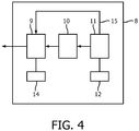
- Fig. 4 schematically depicts a RF transmitter 8 according to a third preferred embodiment of the invention.
- This third preferred embodiment of the invention resembles the second preferred embodiment of the invention described before wherein in addition to the charging of the RF amplifier 9 by the capacitor bank 10 a direct charging of the RF amplifier 9 by the mains power supply 11 is possible due to a direct current line 15 between the mains power supply 11 and the RF amplifier 9.
- a direct current line 15 between the mains power supply 11 and the RF amplifier 9.
- a MR system 1 according to a fourth preferred embodiment is shown.
- the present MRI system 1 according to the fourth preferred embodiment of the invention is controlled by a MRI control unit 16, which is omitted in Fig. 1 but explicitly depicted in Fig. 5 .
- This MRI control unit 16 is coupled to an information unit 17, which is further coupled to the RF transmitter 8 according to the fourth preferred embodiment of the invention.
- This RF transmitter 8 is depicted in more detail in Fig. 6 . From Fig. 6 it can be seen that the information unit 17 is coupled to the power supply control unit 12. Actually, the information unit 17 receives information from MRI control unit 16 about the MRI process performed by the MRI system 1.
- the information unit 17 generates an indication signal on the basis of the upcoming current drawn from the capacitor bank 10 on the basis of the upcoming RF power demand for the transmit coil 5 of the MRI system, which is fed to the information unit 17 by the MRI control unit 16. In this way, it is even possible to feed a charging current to the capacitor bank 10 directly before a RF pulse is generated and forwarded to the RF transmit coil 5.
- this embodiment makes it possible to prevent conceivable drops in available RF power on the basis of the planned MRI process, which is executed by the MRI system 1.
- the present invention addresses the power supply control for the RF amplifier 9 of the RF transmitter 8 of a MRI system 1 by using extra information on required charging current for the capacitor bank 10. This information is used to activate the recharging of the capacitor bank 10 in time and in some cases even before a RF energy drop has occurred. In this way, the generation of RF pulses for MRI applications becomes more efficient making it possible to use smaller capacitor bank values at the same performance level of the system.
Landscapes
- Physics & Mathematics (AREA)
- Condensed Matter Physics & Semiconductors (AREA)
- General Physics & Mathematics (AREA)
- Magnetic Resonance Imaging Apparatus (AREA)
Priority Applications (6)
| Application Number | Priority Date | Filing Date | Title |
|---|---|---|---|
| EP18202021.4A EP3644084A1 (en) | 2018-10-23 | 2018-10-23 | Generation of rf pulses for mri applications |
| EP19787275.7A EP3870988B1 (en) | 2018-10-23 | 2019-10-21 | Generation of rf pulses for mri applications |
| US17/286,828 US11550008B2 (en) | 2018-10-23 | 2019-10-21 | Generation of RF pulses for MRI applications |
| CN201980070107.4A CN112955766B (zh) | 2018-10-23 | 2019-10-21 | 用于生成用于mri系统的rf脉冲的mri系统和方法 |
| JP2021521463A JP7337920B2 (ja) | 2018-10-23 | 2019-10-21 | Mri用途のためのrfパルスの生成 |
| PCT/EP2019/078480 WO2020083802A1 (en) | 2018-10-23 | 2019-10-21 | Generation of rf pulses for mri applications |
Applications Claiming Priority (1)
| Application Number | Priority Date | Filing Date | Title |
|---|---|---|---|
| EP18202021.4A EP3644084A1 (en) | 2018-10-23 | 2018-10-23 | Generation of rf pulses for mri applications |
Publications (1)
| Publication Number | Publication Date |
|---|---|
| EP3644084A1 true EP3644084A1 (en) | 2020-04-29 |
Family
ID=63965370
Family Applications (2)
| Application Number | Title | Priority Date | Filing Date |
|---|---|---|---|
| EP18202021.4A Withdrawn EP3644084A1 (en) | 2018-10-23 | 2018-10-23 | Generation of rf pulses for mri applications |
| EP19787275.7A Active EP3870988B1 (en) | 2018-10-23 | 2019-10-21 | Generation of rf pulses for mri applications |
Family Applications After (1)
| Application Number | Title | Priority Date | Filing Date |
|---|---|---|---|
| EP19787275.7A Active EP3870988B1 (en) | 2018-10-23 | 2019-10-21 | Generation of rf pulses for mri applications |
Country Status (5)
| Country | Link |
|---|---|
| US (1) | US11550008B2 (https=) |
| EP (2) | EP3644084A1 (https=) |
| JP (1) | JP7337920B2 (https=) |
| CN (1) | CN112955766B (https=) |
| WO (1) | WO2020083802A1 (https=) |
Cited By (1)
| Publication number | Priority date | Publication date | Assignee | Title |
|---|---|---|---|---|
| CN115395604A (zh) * | 2022-08-24 | 2022-11-25 | 北京万东医疗科技股份有限公司 | 一种电容充电控制方法、射频放大器及磁共振设备 |
Families Citing this family (1)
| Publication number | Priority date | Publication date | Assignee | Title |
|---|---|---|---|---|
| US20240141779A1 (en) * | 2022-10-28 | 2024-05-02 | Aps Technology, Llc | Rotary pulser with regenerative control |
Citations (2)
| Publication number | Priority date | Publication date | Assignee | Title |
|---|---|---|---|---|
| EP2893876A1 (en) * | 2012-09-10 | 2015-07-15 | Kabushiki Kaisha Toshiba | Magnetic resonance imaging equipment, and power control method for magnetic resonance imaging equipment |
| US20170261573A1 (en) | 2016-03-10 | 2017-09-14 | Toshiba Medical Systems Corporation | Magnetic resonance imaging apparatus |
Family Cites Families (17)
| Publication number | Priority date | Publication date | Assignee | Title |
|---|---|---|---|---|
| JPH04129532A (ja) * | 1990-09-19 | 1992-04-30 | Toshiba Corp | 傾斜磁場アンプ装置 |
| JP2716105B2 (ja) * | 1991-06-24 | 1998-02-18 | 株式会社日立製作所 | 交番定電流回路 |
| US5451878A (en) * | 1994-07-15 | 1995-09-19 | General Electric Company | Non-resonant gradient field accelerator |
| GB9616499D0 (en) * | 1996-08-06 | 1996-09-25 | Oxford Instr Uk Ltd | Magnetic field pulse generator |
| US7880330B2 (en) * | 2004-06-18 | 2011-02-01 | Bose Corporation | Controlling a power converter |
| US7382128B2 (en) * | 2006-02-24 | 2008-06-03 | Kenergy, Inc. | Magnetic resonance imaging system with a Class-E radio frequency amplifier |
| EP2352199B1 (en) * | 2008-11-21 | 2015-08-26 | Honda Motor Co., Ltd. | Charge control device |
| WO2012114217A1 (en) * | 2011-02-22 | 2012-08-30 | Koninklijke Philips Electronics N.V. | Mri rf power amplifier with modulated power supply |
| CN103547937B (zh) * | 2011-05-23 | 2016-09-21 | 皇家飞利浦有限公司 | 作为用于mri rf 线圈的失谐电路的fet 开关 |
| EP2729824B1 (en) * | 2011-07-04 | 2021-05-12 | Koninklijke Philips N.V. | Magnetic resonance imaging system with a multi-channel impedance matching network |
| KR101343037B1 (ko) * | 2011-11-10 | 2013-12-18 | 삼성전자 주식회사 | 자기 공명 영상용 무선 고주파 코일, 그 코일의 전원 제어 방법 및 그 코일을 이용한 자기 공명 영상 장치 |
| US9897672B2 (en) | 2012-04-16 | 2018-02-20 | Koninklijke Philips Electronics N.V. | MRI gradient power system with add on energy buffer |
| JP6373679B2 (ja) * | 2014-07-28 | 2018-08-15 | キヤノンメディカルシステムズ株式会社 | Rfコイル保管装置 |
| US10564238B2 (en) * | 2014-12-17 | 2020-02-18 | General Electric Company | Systems and methods for energizing magnets of magnetic resonance imaging (MRI) systems |
| US10067203B2 (en) * | 2015-10-09 | 2018-09-04 | General Electric Company | Energy storage solution for an MRI system |
| JP6611589B2 (ja) | 2015-12-17 | 2019-11-27 | キヤノンメディカルシステムズ株式会社 | 磁気共鳴イメージング装置 |
| CN107260327B (zh) | 2016-03-31 | 2021-01-05 | 通用电气公司 | 用于操控医疗成像装置的峰值功率要求的系统和方法 |
-
2018
- 2018-10-23 EP EP18202021.4A patent/EP3644084A1/en not_active Withdrawn
-
2019
- 2019-10-21 WO PCT/EP2019/078480 patent/WO2020083802A1/en not_active Ceased
- 2019-10-21 US US17/286,828 patent/US11550008B2/en active Active
- 2019-10-21 EP EP19787275.7A patent/EP3870988B1/en active Active
- 2019-10-21 CN CN201980070107.4A patent/CN112955766B/zh active Active
- 2019-10-21 JP JP2021521463A patent/JP7337920B2/ja active Active
Patent Citations (2)
| Publication number | Priority date | Publication date | Assignee | Title |
|---|---|---|---|---|
| EP2893876A1 (en) * | 2012-09-10 | 2015-07-15 | Kabushiki Kaisha Toshiba | Magnetic resonance imaging equipment, and power control method for magnetic resonance imaging equipment |
| US20170261573A1 (en) | 2016-03-10 | 2017-09-14 | Toshiba Medical Systems Corporation | Magnetic resonance imaging apparatus |
Cited By (1)
| Publication number | Priority date | Publication date | Assignee | Title |
|---|---|---|---|---|
| CN115395604A (zh) * | 2022-08-24 | 2022-11-25 | 北京万东医疗科技股份有限公司 | 一种电容充电控制方法、射频放大器及磁共振设备 |
Also Published As
| Publication number | Publication date |
|---|---|
| CN112955766A (zh) | 2021-06-11 |
| US20210382125A1 (en) | 2021-12-09 |
| CN112955766B (zh) | 2025-03-11 |
| EP3870988A1 (en) | 2021-09-01 |
| JP7337920B2 (ja) | 2023-09-04 |
| JP2022505429A (ja) | 2022-01-14 |
| US11550008B2 (en) | 2023-01-10 |
| EP3870988B1 (en) | 2025-04-16 |
| WO2020083802A1 (en) | 2020-04-30 |
Similar Documents
| Publication | Publication Date | Title |
|---|---|---|
| TWI710782B (zh) | 用於對操作磁共振成像系統之至少一梯度線圈提供電力之裝置及方法以及磁共振成像系統 | |
| EP2674774B1 (en) | Wireless transmit and receive MRI coils | |
| EP3164728B1 (en) | Mr receive coil with detune circuit and energy harvesting circuit | |
| US9658302B2 (en) | Apparatus and method for synchronizing clocks between devices of magnetic resonance imaging (MRI) system | |
| US10739431B2 (en) | Magnetic resonance examination system with a user interface | |
| AU2020261267A1 (en) | Techniques for dynamic control of a Magnetic Resonance Imaging system | |
| EP2989478B1 (en) | Single coaxial interface for magnetic resonance (mr) coils | |
| EP3870988B1 (en) | Generation of rf pulses for mri applications | |
| US20020145424A1 (en) | Method of correcting resonance frequency variation and MRI apparatus | |
| US20100253344A1 (en) | Magnetic resonance method and apparatus to determine k-space positions for modeling radio-frequency pulses | |
| CN107209235A (zh) | 多通道rf线圈组件的自动阻抗调节 | |
| US10732243B2 (en) | Method and apparatus for optimization of a time progression of a magnetic resonance control sequence | |
| WO2022187666A8 (en) | Systems and methods for performing magnetic resonance imaging with reduced operator interaction | |
| KR101718105B1 (ko) | 자기 공명 시스템의 제어 | |
| US10371771B2 (en) | Gradient amplifier system for driving a gradient coil and configuration method | |
| CN103513197B (zh) | 确定磁共振成像设备中的通信等待时间的方法 | |
| US20180031652A1 (en) | Magnetic resonance imaging apparatus and method with slice-specific adjustment of radio frequency pulses to current ambient conditions | |
| US20190212405A1 (en) | Magnetic resonance imaging apparatus, and method for the operation thereof | |
| US10416249B2 (en) | Adaptive pin diode drive circuit with minimized power loss | |
| US10295637B2 (en) | Scan condition determining apparatus, magnetic resonance apparatus, scan condition determining method, and program | |
| JP2002360532A (ja) | Mrデータ収集方法およびmri装置 | |
| US11016163B2 (en) | Magnetic resonance apparatus and gradient magnetic field-dependent control thereof | |
| US10928466B2 (en) | Magnetic resonance apparatus and operating method therefor with monitoring and control of RF energy-relevant operating value |
Legal Events
| Date | Code | Title | Description |
|---|---|---|---|
| PUAI | Public reference made under article 153(3) epc to a published international application that has entered the european phase |
Free format text: ORIGINAL CODE: 0009012 |
|
| STAA | Information on the status of an ep patent application or granted ep patent |
Free format text: STATUS: THE APPLICATION HAS BEEN PUBLISHED |
|
| AK | Designated contracting states |
Kind code of ref document: A1 Designated state(s): AL AT BE BG CH CY CZ DE DK EE ES FI FR GB GR HR HU IE IS IT LI LT LU LV MC MK MT NL NO PL PT RO RS SE SI SK SM TR |
|
| AX | Request for extension of the european patent |
Extension state: BA ME |
|
| STAA | Information on the status of an ep patent application or granted ep patent |
Free format text: STATUS: THE APPLICATION IS DEEMED TO BE WITHDRAWN |
|
| 18D | Application deemed to be withdrawn |
Effective date: 20201030 |