EP3644072A1 - Over-the-air measurement chamber and over-the-air measurement method - Google Patents
Over-the-air measurement chamber and over-the-air measurement method Download PDFInfo
- Publication number
- EP3644072A1 EP3644072A1 EP18202760.7A EP18202760A EP3644072A1 EP 3644072 A1 EP3644072 A1 EP 3644072A1 EP 18202760 A EP18202760 A EP 18202760A EP 3644072 A1 EP3644072 A1 EP 3644072A1
- Authority
- EP
- European Patent Office
- Prior art keywords
- over
- air measurement
- measurement chamber
- rotational axis
- gas
- Prior art date
- Legal status (The legal status is an assumption and is not a legal conclusion. Google has not performed a legal analysis and makes no representation as to the accuracy of the status listed.)
- Granted
Links
Images

Classifications
-
- H—ELECTRICITY
- H04—ELECTRIC COMMUNICATION TECHNIQUE
- H04L—TRANSMISSION OF DIGITAL INFORMATION, e.g. TELEGRAPHIC COMMUNICATION
- H04L43/00—Arrangements for monitoring or testing data switching networks
- H04L43/08—Monitoring or testing based on specific metrics, e.g. QoS, energy consumption or environmental parameters
- H04L43/0805—Monitoring or testing based on specific metrics, e.g. QoS, energy consumption or environmental parameters by checking availability
- H04L43/0811—Monitoring or testing based on specific metrics, e.g. QoS, energy consumption or environmental parameters by checking availability by checking connectivity
-
- G—PHYSICS
- G01—MEASURING; TESTING
- G01R—MEASURING ELECTRIC VARIABLES; MEASURING MAGNETIC VARIABLES
- G01R29/00—Arrangements for measuring or indicating electric quantities not covered by groups G01R19/00 - G01R27/00
- G01R29/08—Measuring electromagnetic field characteristics
- G01R29/10—Radiation diagrams of antennas
- G01R29/105—Radiation diagrams of antennas using anechoic chambers; Chambers or open field sites used therefor
-
- H—ELECTRICITY
- H04—ELECTRIC COMMUNICATION TECHNIQUE
- H04M—TELEPHONIC COMMUNICATION
- H04M1/00—Substation equipment, e.g. for use by subscribers
- H04M1/24—Arrangements for testing
-
- H—ELECTRICITY
- H05—ELECTRIC TECHNIQUES NOT OTHERWISE PROVIDED FOR
- H05K—PRINTED CIRCUITS; CASINGS OR CONSTRUCTIONAL DETAILS OF ELECTRIC APPARATUS; MANUFACTURE OF ASSEMBLAGES OF ELECTRICAL COMPONENTS
- H05K5/00—Casings, cabinets or drawers for electric apparatus
- H05K5/0091—Housing specially adapted for small components
- H05K5/0095—Housing specially adapted for small components hermetically-sealed
-
- H—ELECTRICITY
- H05—ELECTRIC TECHNIQUES NOT OTHERWISE PROVIDED FOR
- H05K—PRINTED CIRCUITS; CASINGS OR CONSTRUCTIONAL DETAILS OF ELECTRIC APPARATUS; MANUFACTURE OF ASSEMBLAGES OF ELECTRICAL COMPONENTS
- H05K5/00—Casings, cabinets or drawers for electric apparatus
- H05K5/06—Hermetically-sealed casings
- H05K5/069—Other details of the casing, e.g. wall structure, passage for a connector, a cable, a shaft
-
- H—ELECTRICITY
- H05—ELECTRIC TECHNIQUES NOT OTHERWISE PROVIDED FOR
- H05K—PRINTED CIRCUITS; CASINGS OR CONSTRUCTIONAL DETAILS OF ELECTRIC APPARATUS; MANUFACTURE OF ASSEMBLAGES OF ELECTRICAL COMPONENTS
- H05K7/00—Constructional details common to different types of electric apparatus
- H05K7/20—Modifications to facilitate cooling, ventilating, or heating
- H05K7/20009—Modifications to facilitate cooling, ventilating, or heating using a gaseous coolant in electronic enclosures
- H05K7/20136—Forced ventilation, e.g. by fans
-
- H—ELECTRICITY
- H04—ELECTRIC COMMUNICATION TECHNIQUE
- H04W—WIRELESS COMMUNICATION NETWORKS
- H04W24/00—Supervisory, monitoring or testing arrangements
- H04W24/06—Testing, supervising or monitoring using simulated traffic
Definitions
- the invention relates to an over-the-air measurement chamber for performing measurements, especially measurements regarding wireless connectivity capabilities under different temperature conditions, with respect to a device under test and a corresponding over-the-air measurement method.
- EP 3 035 730 B1 relates to a measurement housing adapted to receive at least one mobile communication device for measurement of a wireless communication of said mobile communication device, wherein said measurement housing is transparent to high frequency signals and comprises a temperature control unit adapted to control an internal temperature within said measurement housing.
- the mobile communication device cannot be positioned in a flexible manner during measuring, which disadvantageously leads to a limited accuracy and a reduced efficiency of the respective measurement.
- an over-the-air measurement chamber and an over-the-air measurement method in order to allow for performing measurements, especially measurements regarding wireless connectivity capabilities under different temperature conditions, with respect to a device under test in a flexible manner, thereby ensuring a high accuracy and efficiency of the measurement.
- an over-the-air measurement chamber for performing measurements with respect to a device under test.
- the over-the-air measurement chamber comprises a thermally isolated space inside the over-the-air measurement chamber, a positioner for positioning the device under test, wherein the positioner comprises an inner portion and an outer rotational unit, and two gas guiding means for gas intake and gas out-take.
- the two gas guiding means are fed into the inner portion of the positioner through a hollow rotational axis of the outer rotational unit.
- the thermally isolated space surrounds the device under test.
- the inner portion comprises the thermally isolated space.
- the thermally isolated space is of spherical or ellipsoidal shape. Additionally or alternatively, the thermally isolated space is a thermally isolated bubble or a kind thereof.
- complexity can further be reduced, which leads to a further increased measurement efficiency.
- the thermally isolated space is formed by a radio frequency neutral material.
- the thermally isolated space comprises a radio frequency neutral upper dome.
- the inner portion of the positioner comprises an inner rotational axis.
- the inner rotational axis is configured to rotatably hold the device under test.
- complexity can further be reduced, thereby ensuring an increased measurement efficiency.
- the inner rotational axis may especially be independently rotatable from the inner portion.
- a rubber ring may preferably allow the inner rotational axis to rotate independently from the inner portion of the positioner.
- the hollow rotational axis is independently rotatable from the inner rotational axis.
- flexibility, and thus also measurement efficiency, can further be increased.
- the hollow rotational axis and the inner rotational axis form an angle between 5 and 90 degrees, preferably between 45 and 90 degrees, more preferably between 60 and 90 degrees, most preferably between 80 and 90 degrees.
- flexibility can further be increased, which leads to an increased measurement efficiency.
- the gas guided by the two gas guiding means comprises heated gas or cooled gas. Additionally or alternatively, the gas guided by the two gas guiding means comprises at least one of air, nitrogen, or sulfur hexafluoride.
- flexibility can further be increased, thereby especially ensuring an increased measurement efficiency.
- At least one of the two gas guiding means comprises at least one of a hose, a pipe, a corrugated pipe, a bellows-based hose, or a bellows-based pipe.
- a hose a pipe, a corrugated pipe, a bellows-based hose, or a bellows-based pipe.
- each of the two gas guiding means fed into the inner portion comprises a rotary joint which is configured for compressed gas type applications such that the hollow rotational axis is independently rotatable of corresponding stationary gas guiding means being outside the outer rotational unit.
- the two gas guiding means fed into the inner portion are rotatable with the outer rotational unit.
- gas can efficiently be guided without loss.
- the two gas guiding means fed into the inner portion are connected to the thermally isolated space.
- gas can efficiently be guided into the thermally isolated space.
- the inner portion of the positioner is rotatable around the hollow rotational axis.
- the outer rotational unit is rotatable around the hollow rotational axis.
- the positioner further comprises a stationary base.
- the stationary base is configured to rotatably hold the hollow rotational axis.
- the stationary base is configured to rotatably hold the inner portion.
- the stationary base is configured to rotatably hold the outer rotation unit.
- the positioner allows for a secure stand, thereby avoiding positioning errors.
- the over-the-air measurement chamber further comprises a feedthrough configured to get the two gas guiding means into and out of the over-the-air measurement chamber.
- a feedthrough configured to get the two gas guiding means into and out of the over-the-air measurement chamber.
- any unit for gas intake and/or out-take - such as a heated or cooled air generation unit - inside the over-the-air measurement chamber.
- said unit for gas intake and/or out-take preferably in the form of a tempered air generation unit, may be placed inside the over-the-air measurement chamber.
- the over-the-air measurement chamber may further comprise a tempered air generation unit.
- an over-the-air measurement method comprises the steps of placing a device under test into an over-the-air measurement chamber according to the first aspect of the invention or any preferred implementation form thereof, and performing at least one over-the-air measurement with respect to the device under test.
- measurements regarding wireless connectivity capabilities can be performed under different temperature conditions in a flexible manner, thereby ensuring a high accuracy and efficiency of the measurement.
- FIG. 1 a block diagram of an exemplary embodiment of an over-the-air measurement chamber 1 for performing measurements with respect to a device under test 2 is shown.
- the over-the-air measurement chamber 1 comprises a thermally isolated space 3 inside the over-the-air measurement chamber 1, a positioner 4 for positioning the device under test 2, wherein the positioner 4 comprises an inner portion 5 and an outer rotational unit 6, and two gas guiding means 7a, 7b for gas intake and gas out-take.
- the two gas guiding means 7a, 7b are fed into the inner portion 5 of the positioner 4 through a hollow rotational axis 8 of the outer rotational unit 6.
- the thermally isolated space 3 surrounds the device under test 2.
- the inner portion 5 comprises the thermally isolated space 3.
- the thermally isolated space 3 is attached to the inner portion 5.
- the thermally isolated space 3 is a thermally isolated bubble, which is formed by a radio frequency neutral material.
- said thermally isolated bubble may be made from rohacell.
- the thermally isolated bubble comprises a radio frequency neutral upper dome.
- thermally isolated space 3 or the thermally isolated bubble may especially be based on a double-walled design in order to allow for a high thermal insulation.
- the space between the respective walls of the double-walled design may preferably comprise air or a vacuum.
- the over-the-air measurement chamber 1 may optionally comprise a compact antenna test range (CATR) reflector.
- CATR compact antenna test range
- said CATR reflector may be located inside the over-the-air measurement chamber and/or outside the thermally isolated space 3.
- the CATR reflector is optional, since far-field conditions with special respect to the device under test 2 can be established in a direct manner especially without the reflector or in an indirect manner especially with the reflector.
- the inner portion 5 of the positioner 4 comprises an inner rotational axis 9.
- Said inner rotational axis 9 is configured to rotatably hold the device under test 2.
- the inner rotational axis 9 is independently rotatable from the inner portion 5.
- a rubber ring may preferably allow the inner rotational axis 9 to rotate independently from the inner portion 5 of the positioner 4.
- the gas guided by the two gas guiding means 7a, 7b may especially comprises heated gas or cooled gas. It is further noted that additionally or alternatively, the gas guided by the two gas guiding means 7a, 7b may comprise at least one of air, nitrogen, or sulfur hexafluoride.
- At least one of the two gas guiding means 7a, 7b comprises at least one of a hose, a pipe, a corrugated pipe, a bellows-based hose, or a bellows-based pipe.
- each of the two gas guiding means 7a, 7b fed into the inner portion 5 comprises a rotary joint 10a, 10b which is configured for compressed gas type applications such that the hollow rotational axis 8 is independently rotatable of corresponding stationary gas guiding means 13a, 13b being outside the outer rotational unit 6.
- the two gas guiding means 7a, 7b fed into the inner portion 5 are rotatable with the outer rotational unit 6.
- the two gas guiding means 7a, 7b fed into the inner portion 5 are connected to the thermally isolated space 3 or the thermally isolated bubble, respectively.
- both the inner portion 5 of the positioner 4 and the outer rotational unit 6 are rotatable around the hollow rotational axis 8.
- the positioner 4 further comprises a stationary base 11.
- the stationary base is configured to rotatably hold each of the hollow rotational axis 8, the inner portion 5, and the outer rotation unit 6.
- the hollow rotational axis 8 is independently rotatable from the inner rotational axis 9.
- the hollow rotational axis 8 and the inner rotational axis 9 form an angle between 5 and 90 degrees, preferably between 45 and 90 degrees, more preferably between 60 and 90 degrees, most preferably between 80 and 90 degrees.
- the hollow rotational axis 8 is perpendicular to the inner rotational axis 9.
- the over-the-air measurement chamber 1 further comprises a feedthrough 12 configured to get the two gas guiding means, especially the stationary gas guiding means 13a, 13b, into and out of the over-the-air measurement chamber 1.
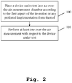
- Fig. 2 shows a flow chart of an embodiment of the inventive method.
- a device under test is placed into an over-the-air measurement chamber according to the first aspect of the invention or any preferred implementation form thereof.
- a second step S101 at least one over-the-air measurement is performed with respect to the device under test.
Landscapes
- Engineering & Computer Science (AREA)
- Microelectronics & Electronic Packaging (AREA)
- Physics & Mathematics (AREA)
- Signal Processing (AREA)
- Thermal Sciences (AREA)
- Electromagnetism (AREA)
- General Physics & Mathematics (AREA)
- Environmental & Geological Engineering (AREA)
- Computer Networks & Wireless Communication (AREA)
- Testing Of Devices, Machine Parts, Or Other Structures Thereof (AREA)
- Arrangements For Transmission Of Measured Signals (AREA)
Abstract
Description
- The invention relates to an over-the-air measurement chamber for performing measurements, especially measurements regarding wireless connectivity capabilities under different temperature conditions, with respect to a device under test and a corresponding over-the-air measurement method.
- Generally, in times of an increasing number of communication applications providing wireless connectivity capabilities, there is a growing need of an over-the-air measurement chamber and an over-the-air measurement method for performing measurements with respect to such applications in order to verify their correct functioning especially under different temperature conditions.
-
EP 3 035 730 B1 - Accordingly, there is the object to provide an over-the-air measurement chamber and an over-the-air measurement method in order to allow for performing measurements, especially measurements regarding wireless connectivity capabilities under different temperature conditions, with respect to a device under test in a flexible manner, thereby ensuring a high accuracy and efficiency of the measurement.
- This object is solved by the features of the first independent claim for an over-the-air measurement chamber for performing measurements with respect to a device under test and the features of the second independent claim for an over-the-air measurement method. The dependent claims contain further developments.
- According to a first aspect of the invention, an over-the-air measurement chamber for performing measurements with respect to a device under test is provided. The over-the-air measurement chamber comprises a thermally isolated space inside the over-the-air measurement chamber, a positioner for positioning the device under test, wherein the positioner comprises an inner portion and an outer rotational unit, and two gas guiding means for gas intake and gas out-take. In this context, the two gas guiding means are fed into the inner portion of the positioner through a hollow rotational axis of the outer rotational unit. Advantageously, in this manner, measurements regarding wireless connectivity capabilities can be performed under different temperature conditions in a flexible manner, thereby ensuring a high accuracy and efficiency of the measurement.
- According to a first preferred implementation form of the first aspect of the invention, the thermally isolated space surrounds the device under test. In addition to this or as an alternative, the inner portion comprises the thermally isolated space. Advantageously, for instance, complexity can be reduced, thereby increasing measurement efficiency.
- According to a second preferred implementation form of the first aspect of the invention, the thermally isolated space is of spherical or ellipsoidal shape. Additionally or alternatively, the thermally isolated space is a thermally isolated bubble or a kind thereof. Advantageously, for example, complexity can further be reduced, which leads to a further increased measurement efficiency.
- According to a further preferred implementation form of the first aspect of the invention, the thermally isolated space is formed by a radio frequency neutral material. In addition to this or as an alternative, the thermally isolated space comprises a radio frequency neutral upper dome. Advantageously, for example, distorted measurement results can be avoided, thereby ensuring a high accuracy.
- According to a further preferred implementation form of the first aspect of the invention, the inner portion of the positioner comprises an inner rotational axis. In this context, the inner rotational axis is configured to rotatably hold the device under test. Advantageously, for instance, complexity can further be reduced, thereby ensuring an increased measurement efficiency. Further advantageously, the inner rotational axis may especially be independently rotatable from the inner portion. Additionally, it is noted that a rubber ring may preferably allow the inner rotational axis to rotate independently from the inner portion of the positioner.
- According to a further preferred implementation form of the first aspect of the invention, the hollow rotational axis is independently rotatable from the inner rotational axis. Advantageously, in this manner, flexibility, and thus also measurement efficiency, can further be increased.
- According to a further preferred implementation form of the first aspect of the invention, the hollow rotational axis and the inner rotational axis form an angle between 5 and 90 degrees, preferably between 45 and 90 degrees, more preferably between 60 and 90 degrees, most preferably between 80 and 90 degrees. Advantageously, flexibility can further be increased, which leads to an increased measurement efficiency.
- According to a further preferred implementation form of the first aspect of the invention, the gas guided by the two gas guiding means comprises heated gas or cooled gas. Additionally or alternatively, the gas guided by the two gas guiding means comprises at least one of air, nitrogen, or sulfur hexafluoride. Advantageously, for instance, flexibility can further be increased, thereby especially ensuring an increased measurement efficiency.
- According to a further preferred implementation form of the first aspect of the invention, at least one of the two gas guiding means comprises at least one of a hose, a pipe, a corrugated pipe, a bellows-based hose, or a bellows-based pipe. Advantageously, for example, not only complexity can be reduced but also flexibility can be increased, which leads to an increased measurement efficiency.
- According to a further preferred implementation form of the first aspect of the invention, each of the two gas guiding means fed into the inner portion comprises a rotary joint which is configured for compressed gas type applications such that the hollow rotational axis is independently rotatable of corresponding stationary gas guiding means being outside the outer rotational unit. Additionally or alternatively, the two gas guiding means fed into the inner portion are rotatable with the outer rotational unit. Advantageously, for instance, gas can efficiently be guided without loss.
- According to a further preferred implementation form of the first aspect of the invention, the two gas guiding means fed into the inner portion are connected to the thermally isolated space. Advantageously, for example, gas can efficiently be guided into the thermally isolated space.
- According to a further preferred implementation form of the first aspect of the invention, the inner portion of the positioner is rotatable around the hollow rotational axis. In addition to this or as an alternative, the outer rotational unit is rotatable around the hollow rotational axis. Advantageously, complexity can be further reduced, thereby ensuring an increased measurement efficiency.
- According to a further preferred implementation form of the first aspect of the invention, the positioner further comprises a stationary base. In this context, the stationary base is configured to rotatably hold the hollow rotational axis. In addition to this or as an alternative, the stationary base is configured to rotatably hold the inner portion. Further additionally or further alternatively, the stationary base is configured to rotatably hold the outer rotation unit. Advantageously, for instance, the positioner allows for a secure stand, thereby avoiding positioning errors.
- According to a further preferred implementation form of the first aspect of the invention, the over-the-air measurement chamber further comprises a feedthrough configured to get the two gas guiding means into and out of the over-the-air measurement chamber. Advantageously, it is not necessary to place any unit for gas intake and/or out-take - such as a heated or cooled air generation unit - inside the over-the-air measurement chamber. However, as an alternative, it is noted that said unit for gas intake and/or out-take, preferably in the form of a tempered air generation unit, may be placed inside the over-the-air measurement chamber. In other words, the over-the-air measurement chamber may further comprise a tempered air generation unit.
- According to a second aspect of the invention, an over-the-air measurement method is provided. The over-the-air measurement method comprises the steps of placing a device under test into an over-the-air measurement chamber according to the first aspect of the invention or any preferred implementation form thereof, and performing at least one over-the-air measurement with respect to the device under test. Advantageously, in this manner, measurements regarding wireless connectivity capabilities can be performed under different temperature conditions in a flexible manner, thereby ensuring a high accuracy and efficiency of the measurement.
- Exemplary embodiments of the invention are now further explained with respect to the drawings by way of example only, and not for limitation. In the drawings:
-
Fig. 1 shows an exemplary embodiment of an inventive over-the-air measurement chamber; and -
Fig. 2 shows a flow chart of an embodiment of the second aspect of the invention. - With respect to
Fig. 1 , a block diagram of an exemplary embodiment of an over-the-air measurement chamber 1 for performing measurements with respect to a device undertest 2 is shown. - According to
Fig. 1 , the over-the-air measurement chamber 1 comprises a thermally isolatedspace 3 inside the over-the-air measurement chamber 1, apositioner 4 for positioning the device undertest 2, wherein thepositioner 4 comprises aninner portion 5 and an outerrotational unit 6, and two gas guiding means 7a, 7b for gas intake and gas out-take. As it can be seen, the two gas guiding means 7a, 7b are fed into theinner portion 5 of thepositioner 4 through a hollowrotational axis 8 of the outerrotational unit 6. - As it can further be seen from
Fig. 1 , the thermally isolatedspace 3 surrounds the device undertest 2. In addition to this, theinner portion 5 comprises the thermallyisolated space 3. In other words, the thermallyisolated space 3 is attached to theinner portion 5. - Furthermore, in this exemplary case the thermally isolated
space 3 is a thermally isolated bubble, which is formed by a radio frequency neutral material. Preferably, said thermally isolated bubble may be made from rohacell. According toFig. 1 , in other words, the thermally isolated bubble comprises a radio frequency neutral upper dome. - It is further noted that the thermally isolated
space 3 or the thermally isolated bubble may especially be based on a double-walled design in order to allow for a high thermal insulation. In this context, the space between the respective walls of the double-walled design may preferably comprise air or a vacuum. - With respect to the over-the-
air measurement chamber 1, it should generally be mentioned that the over-the-air measurement chamber 1 may optionally comprise a compact antenna test range (CATR) reflector. Preferably, said CATR reflector may be located inside the over-the-air measurement chamber and/or outside the thermally isolatedspace 3. In this context, it is noted that the CATR reflector is optional, since far-field conditions with special respect to the device undertest 2 can be established in a direct manner especially without the reflector or in an indirect manner especially with the reflector. - Moreover, the
inner portion 5 of thepositioner 4 comprises an innerrotational axis 9. Said innerrotational axis 9 is configured to rotatably hold the device undertest 2. Additionally, in this exemplary case, the innerrotational axis 9 is independently rotatable from theinner portion 5. In this context, it is noted that, for instance, a rubber ring may preferably allow the innerrotational axis 9 to rotate independently from theinner portion 5 of thepositioner 4. - With respect to the gas guided by the two gas guiding means 7a, 7b, it is noted that said gas may especially comprises heated gas or cooled gas. It is further noted that additionally or alternatively, the gas guided by the two gas guiding means 7a, 7b may comprise at least one of air, nitrogen, or sulfur hexafluoride.
- With respect to the gas guiding means 7a, 7b, it should be mentioned that at least one of the two gas guiding means 7a, 7b comprises at least one of a hose, a pipe, a corrugated pipe, a bellows-based hose, or a bellows-based pipe.
- Furthermore, in accordance with
Fig. 1 , each of the two gas guiding means 7a, 7b fed into theinner portion 5 comprises a rotary joint 10a, 10b which is configured for compressed gas type applications such that the hollowrotational axis 8 is independently rotatable of corresponding stationary gas guiding means 13a, 13b being outside the outerrotational unit 6. In addition to this, the two gas guiding means 7a, 7b fed into theinner portion 5 are rotatable with the outerrotational unit 6. - In further addition to this, the two gas guiding means 7a, 7b fed into the
inner portion 5 are connected to the thermally isolatedspace 3 or the thermally isolated bubble, respectively. - Moreover, in this exemplary case, as it can also be seen from
Fig. 1 , both theinner portion 5 of thepositioner 4 and the outerrotational unit 6 are rotatable around the hollowrotational axis 8. - Additionally, the
positioner 4 further comprises astationary base 11. In this exemplary case according toFig. 1 , the stationary base is configured to rotatably hold each of the hollowrotational axis 8, theinner portion 5, and theouter rotation unit 6. - Furthermore, it should be mentioned that the hollow
rotational axis 8 is independently rotatable from the innerrotational axis 9. - In addition to this or as an alternative, it is further noted that the hollow
rotational axis 8 and the innerrotational axis 9 form an angle between 5 and 90 degrees, preferably between 45 and 90 degrees, more preferably between 60 and 90 degrees, most preferably between 80 and 90 degrees. Exemplarily, as it can be seen, the hollowrotational axis 8 is perpendicular to the innerrotational axis 9. - In addition to this, it should be mentioned that the over-the-
air measurement chamber 1 further comprises afeedthrough 12 configured to get the two gas guiding means, especially the stationary gas guiding means 13a, 13b, into and out of the over-the-air measurement chamber 1. - Finally,
Fig. 2 shows a flow chart of an embodiment of the inventive method. In a first step S100, a device under test is placed into an over-the-air measurement chamber according to the first aspect of the invention or any preferred implementation form thereof. Then, in a second step S101, at least one over-the-air measurement is performed with respect to the device under test. - While various embodiments of the present invention have been described above, it should be understood that they have been presented by way of example only, and not limitation. Numerous changes to the disclosed embodiments can be made in accordance with the disclosure herein without departing from the spirit or scope of the invention. Thus, the breadth and scope of the present invention should not be limited by any of the above described embodiments. Rather, the scope of the invention should be defined in accordance with the following claims and their equivalents.
- Although the invention has been illustrated and described with respect to one or more implementations, equivalent alterations and modifications will occur to others skilled in the art upon the reading and understanding of this specification and the annexed drawings. In addition, while a particular feature of the invention may have been disclosed with respect to only one of several implementations, such feature may be combined with one or more other features of the other implementations as may be desired and advantageous for any given or particular application.
Claims (15)
- An over-the-air measurement chamber (1) for performing measurements with respect to a device under test (2), the over-the-air measurement chamber (1) comprising:a thermally isolated space (3) inside the over-the-air measurement chamber (1),a positioner (4) for positioning the device under test (2), wherein the positioner (4) comprises an inner portion (5) and an outer rotational unit (6), andtwo gas guiding means (7a, 7b) for gas intake and gas out-take,wherein the two gas guiding means (7a, 7b) are fed into the inner portion (5) of the positioner (4) through a hollow rotational axis (8) of the outer rotational unit (6).
- The over-the-air measurement chamber (1) according to claim 1,
wherein the thermally isolated space (3) surrounds the device under test (2), and/or
wherein the inner portion (5) comprises the thermally isolated space (3). - The over-the-air measurement chamber (1) according to claim 1 or 2,
wherein the thermally isolated space (3) is of spherical or ellipsoidal shape, and/or
wherein the thermally isolated space (3) is a thermally isolated bubble or a kind thereof. - The over-the-air measurement chamber according to any of the claims 1 to 3,
wherein the thermally isolated space (3) is formed by a radio frequency neutral material, and/or
wherein the thermally isolated space (3) comprises a radio frequency neutral upper dome. - The over-the-air measurement chamber (1) according to any of the claims 1 to 4,
wherein the inner portion (5) of the positioner (4) comprises an inner rotational axis (9),
wherein the inner rotational axis (9) is configured to rotatably hold the device under test (2). - The over-the-air measurement chamber (1) according to claim 5,
wherein the hollow rotational axis (8) is independently rotatable from the inner rotational axis (9). - The over-the-air measurement chamber (1) according to claim 5 or 6,
wherein the hollow rotational axis (8) and the inner rotational axis (9) form an angle between 5 and 90 degrees, preferably between 45 and 90 degrees, more preferably between 60 and 90 degrees, most preferably between 80 and 90 degrees. - The over-the-air measurement chamber (1) according to any of the claims 1 to 7,
wherein the gas guided by the two gas guiding means (7a, 7b) comprises heated gas or cooled gas, and/or
wherein the gas guided by the two gas guiding means (7a, 7b) comprises at least one of air, nitrogen, or sulfur hexafluoride. - The over-the-air measurement chamber (1) according to any of the claims 1 to 8,
wherein at least one of the two gas guiding means (7a, 7b) comprises at least one of a hose, a pipe, a corrugated pipe, a bellows-based hose, or a bellows-based pipe. - The over-the-air measurement chamber (1) according to any of the claims 1 to 9,
wherein each of the two gas guiding means (7a, 7b) fed into the inner portion (5) comprises a rotary joint (10a, 10b) which is configured for compressed gas type applications such that the hollow rotational axis (8) is independently rotatable of corresponding stationary gas guiding means (13a, 13b) being outside the outer rotational unit (6), and/or
wherein the two gas guiding means (7a, 7b) fed into the inner portion (5) are rotatable with the outer rotational unit (6). - The over-the-air measurement chamber (1) according to any of the claims 1 to 10,
wherein the two gas guiding means (7a, 7b) fed into the inner portion (5) are connected to the thermally isolated space (3). - The over-the-air measurement chamber (1) according to any of the claims 1 to 11,
wherein the inner portion (5) of the positioner (4) is rotatable around the hollow rotational axis (8), and/or wherein the outer rotational unit (6) is rotatable around the hollow rotational axis (8). - The over-the-air measurement chamber (1) according to any of the claims 1 to 12,
wherein the positioner (4) further comprises a stationary base (11),
wherein the stationary base (11) is configured to rotatably hold the hollow rotational axis (8), and/or
wherein the stationary base (11) is configured to rotatably hold the inner portion (5), and/or
wherein the stationary base (11) is configured to rotatably hold the outer rotation unit (6). - The over-the-air measurement chamber (1) according to any of the claims 1 to 13,
wherein the over-the-air measurement chamber (1) further comprises a feedthrough (12) configured to get the two gas guiding means into and out of the over-the-air measurement chamber (1). - An over-the-air measurement method comprising the steps of:placing a device under test (2) into an over-the-air measurement chamber (1) according to any of the claims 1 to 14, andperforming at least one over-the-air measurement with respect to the device under test (2).
Priority Applications (3)
| Application Number | Priority Date | Filing Date | Title |
|---|---|---|---|
| EP18202760.7A EP3644072B8 (en) | 2018-10-26 | 2018-10-26 | Over-the-air measurement chamber and over-the-air measurement method |
| US16/188,653 US10523801B1 (en) | 2018-10-26 | 2018-11-13 | Over-the-air measurement chamber and over-the-air measurement method |
| CN201811622628.XA CN111106978B (en) | 2018-10-26 | 2018-12-28 | Wireless measuring room and wireless measuring method |
Applications Claiming Priority (1)
| Application Number | Priority Date | Filing Date | Title |
|---|---|---|---|
| EP18202760.7A EP3644072B8 (en) | 2018-10-26 | 2018-10-26 | Over-the-air measurement chamber and over-the-air measurement method |
Publications (3)
| Publication Number | Publication Date |
|---|---|
| EP3644072A1 true EP3644072A1 (en) | 2020-04-29 |
| EP3644072B1 EP3644072B1 (en) | 2022-07-27 |
| EP3644072B8 EP3644072B8 (en) | 2022-08-31 |
Family
ID=64109726
Family Applications (1)
| Application Number | Title | Priority Date | Filing Date |
|---|---|---|---|
| EP18202760.7A Active EP3644072B8 (en) | 2018-10-26 | 2018-10-26 | Over-the-air measurement chamber and over-the-air measurement method |
Country Status (3)
| Country | Link |
|---|---|
| US (1) | US10523801B1 (en) |
| EP (1) | EP3644072B8 (en) |
| CN (1) | CN111106978B (en) |
Families Citing this family (3)
| Publication number | Priority date | Publication date | Assignee | Title |
|---|---|---|---|---|
| US10868642B1 (en) * | 2019-09-20 | 2020-12-15 | Rohde & Schwarz Gmbh & Co. Kg | Method and system for early pass/fail determination |
| FI20206357A1 (en) * | 2020-12-22 | 2022-06-23 | Verkotan Oy | SUPPORT STRUCTURE ALLOWING ROTATION FOR THE DEVICE UNDER TEST |
| US11621790B1 (en) * | 2021-10-19 | 2023-04-04 | Rohde & Schwarz Gmbh & Co. Kg | Over-the-air measurement system |
Citations (3)
| Publication number | Priority date | Publication date | Assignee | Title |
|---|---|---|---|---|
| US20030003883A1 (en) * | 2001-07-02 | 2003-01-02 | Wallace Raymond C. | Method and apparatus for testing and evaluating wireless communication devices |
| US20170016944A1 (en) * | 2015-07-16 | 2017-01-19 | Raytheon Company | Methods and Apparatus for Thermal Testing of Antennas |
| EP3035730B1 (en) | 2014-12-19 | 2018-06-06 | Rohde & Schwarz GmbH & Co. KG | A measurement housing for a communication device |
Family Cites Families (10)
| Publication number | Priority date | Publication date | Assignee | Title |
|---|---|---|---|---|
| DE10147200B4 (en) * | 2001-09-25 | 2013-02-21 | Thermo Electron (Karlsruhe) Gmbh | Rotational |
| KR20120111080A (en) * | 2011-03-31 | 2012-10-10 | 비나텍주식회사 | Gas analyzer for cell and gas analyzing method using the same |
| US8904887B2 (en) * | 2011-11-17 | 2014-12-09 | The Aerospace Corporation | Radio frequency transparent thermal window |
| US9116232B2 (en) * | 2012-04-13 | 2015-08-25 | Apple Inc. | Methods and apparatus for testing satellite navigation system receiver performance |
| US9190725B2 (en) * | 2013-03-06 | 2015-11-17 | Apple Inc. | Test system having test stations with adjustable antennas |
| US9244105B2 (en) * | 2013-06-04 | 2016-01-26 | Orbit Advanced Technologies, Inc. | Portable spherical near-field antenna measurement system |
| EP3199957B1 (en) * | 2016-01-29 | 2020-12-30 | Rohde & Schwarz GmbH & Co. KG | Over the air measurement module |
| US10110329B2 (en) * | 2017-02-03 | 2018-10-23 | Rohde & Schwarz Gmbh & Co. Kg | System and method for testing with respect to a far-field region |
| US20180321292A1 (en) * | 2017-05-05 | 2018-11-08 | Rohde & Schwarz Gmbh & Co. Kg | Portable anechoic chamber |
| US10605857B2 (en) * | 2017-05-24 | 2020-03-31 | Rohde & Schwarz Gmbh & Co. Kg | Anechoic chamber for testing a device under test |
-
2018
- 2018-10-26 EP EP18202760.7A patent/EP3644072B8/en active Active
- 2018-11-13 US US16/188,653 patent/US10523801B1/en active Active
- 2018-12-28 CN CN201811622628.XA patent/CN111106978B/en active Active
Patent Citations (3)
| Publication number | Priority date | Publication date | Assignee | Title |
|---|---|---|---|---|
| US20030003883A1 (en) * | 2001-07-02 | 2003-01-02 | Wallace Raymond C. | Method and apparatus for testing and evaluating wireless communication devices |
| EP3035730B1 (en) | 2014-12-19 | 2018-06-06 | Rohde & Schwarz GmbH & Co. KG | A measurement housing for a communication device |
| US20170016944A1 (en) * | 2015-07-16 | 2017-01-19 | Raytheon Company | Methods and Apparatus for Thermal Testing of Antennas |
Non-Patent Citations (2)
| Title |
|---|
| FOGED L J ET AL: "Thermal testing of small antennas in spherical near field system", MICROWAVES, COMMUNICATIONS, ANTENNAS AND ELECTRONICS SYSTEMS (COMCAS), 2011 IEEE INTERNATIONAL CONFERENCE ON, IEEE, 7 November 2011 (2011-11-07), pages 1 - 7, XP032076325, ISBN: 978-1-4577-1692-8, DOI: 10.1109/COMCAS.2011.6105936 * |
| SCHROEDER W L ET AL: "Direct Measurements of Small Antenna Radiation Efficiency by Calorimetric Method", IEEE TRANSACTIONS ON ANTENNAS AND PROPAGATION, IEEE SERVICE CENTER, PISCATAWAY, NJ, US, vol. 54, no. 9, 1 September 2006 (2006-09-01), pages 2646 - 2656, XP001545389, ISSN: 0018-926X, DOI: 10.1109/TAP.2006.880717 * |
Also Published As
| Publication number | Publication date |
|---|---|
| CN111106978B (en) | 2024-03-22 |
| EP3644072B1 (en) | 2022-07-27 |
| CN111106978A (en) | 2020-05-05 |
| EP3644072B8 (en) | 2022-08-31 |
| US10523801B1 (en) | 2019-12-31 |
Similar Documents
| Publication | Publication Date | Title |
|---|---|---|
| CN111244631B (en) | Antenna device and measuring method | |
| EP3644072B1 (en) | Over-the-air measurement chamber and over-the-air measurement method | |
| US11525853B2 (en) | Temperature test apparatus and temperature test method | |
| CN106872801B (en) | A near field test system | |
| CN110031694B (en) | Wireless test system and method for measuring wireless performance of device under test | |
| US11189908B2 (en) | Directional wireless hotspot device and method for pointing a directional antenna | |
| US20200119460A1 (en) | Antenna apparatus and measurement method | |
| EP3167556B1 (en) | Methods and apparatus of operating user equipment in a wireless communication network | |
| US10302735B2 (en) | Wireless terminal antenna directional characteristic measurement system and wireless terminal antenna directional characteristic measurement method | |
| JP7379421B2 (en) | Test equipment and test method | |
| JP5450614B2 (en) | Apparatus for adjusting relative position between electromagnetic probe network and subject, and apparatus for measuring at least one electromagnetic characteristic of subject having electromagnetic probe network | |
| US11754609B2 (en) | Temperature test apparatus and temperature test method | |
| EP3059603A1 (en) | Antenna azimuth alignment monitor | |
| CN107566052A (en) | For characterizing the compact system of the Devices to test with integrated antenna array | |
| CN109286427A (en) | Test device and test method | |
| CN103097899A (en) | Holding device and system for positioning a device for a wireless communication in a measurement environment | |
| US20200264222A1 (en) | Testing system and method with multiple antennas | |
| US7721608B2 (en) | Tray for handling devices to be tested | |
| US10677832B2 (en) | Over the air measurement system and method | |
| CN103460745A (en) | System method and devices related to radio communication equipment | |
| CN112867045A (en) | Multi-compact range measuring system and method | |
| CN210604799U (en) | System for testing antenna performance and OTA index of base station equipment | |
| JP2002158606A (en) | Wireless connection device position calculation system | |
| Boussad et al. | Open-source 4G experimental setup | |
| JP7181951B2 (en) | Temperature test device and temperature test method |
Legal Events
| Date | Code | Title | Description |
|---|---|---|---|
| PUAI | Public reference made under article 153(3) epc to a published international application that has entered the european phase |
Free format text: ORIGINAL CODE: 0009012 |
|
| STAA | Information on the status of an ep patent application or granted ep patent |
Free format text: STATUS: THE APPLICATION HAS BEEN PUBLISHED |
|
| AK | Designated contracting states |
Kind code of ref document: A1 Designated state(s): AL AT BE BG CH CY CZ DE DK EE ES FI FR GB GR HR HU IE IS IT LI LT LU LV MC MK MT NL NO PL PT RO RS SE SI SK SM TR |
|
| AX | Request for extension of the european patent |
Extension state: BA ME |
|
| STAA | Information on the status of an ep patent application or granted ep patent |
Free format text: STATUS: REQUEST FOR EXAMINATION WAS MADE |
|
| 17P | Request for examination filed |
Effective date: 20200826 |
|
| RBV | Designated contracting states (corrected) |
Designated state(s): AL AT BE BG CH CY CZ DE DK EE ES FI FR GB GR HR HU IE IS IT LI LT LU LV MC MK MT NL NO PL PT RO RS SE SI SK SM TR |
|
| GRAP | Despatch of communication of intention to grant a patent |
Free format text: ORIGINAL CODE: EPIDOSNIGR1 |
|
| STAA | Information on the status of an ep patent application or granted ep patent |
Free format text: STATUS: GRANT OF PATENT IS INTENDED |
|
| INTG | Intention to grant announced |
Effective date: 20220510 |
|
| GRAS | Grant fee paid |
Free format text: ORIGINAL CODE: EPIDOSNIGR3 |
|
| GRAA | (expected) grant |
Free format text: ORIGINAL CODE: 0009210 |
|
| STAA | Information on the status of an ep patent application or granted ep patent |
Free format text: STATUS: THE PATENT HAS BEEN GRANTED |
|
| AK | Designated contracting states |
Kind code of ref document: B1 Designated state(s): AL AT BE BG CH CY CZ DE DK EE ES FI FR GB GR HR HU IE IS IT LI LT LU LV MC MK MT NL NO PL PT RO RS SE SI SK SM TR |
|
| RBV | Designated contracting states (corrected) |
Designated state(s): AL AT BE BG CY CZ DE DK EE ES FI FR GB GR HR HU IS IT LT LU LV MC MK MT NL NO PL PT RO RS SE SI SK SM TR |
|
| REG | Reference to a national code |
Ref country code: DE Ref legal event code: R096 Ref document number: 602018038382 Country of ref document: DE |
|
| REG | Reference to a national code |
Ref country code: AT Ref legal event code: REF Ref document number: 1507407 Country of ref document: AT Kind code of ref document: T Effective date: 20220815 |
|
| REG | Reference to a national code |
Ref country code: IE Ref legal event code: FG4D |
|
| REG | Reference to a national code |
Ref country code: LT Ref legal event code: MG9D |
|
| REG | Reference to a national code |
Ref country code: NL Ref legal event code: MP Effective date: 20220727 |
|
| PG25 | Lapsed in a contracting state [announced via postgrant information from national office to epo] |
Ref country code: SE Free format text: LAPSE BECAUSE OF FAILURE TO SUBMIT A TRANSLATION OF THE DESCRIPTION OR TO PAY THE FEE WITHIN THE PRESCRIBED TIME-LIMIT Effective date: 20220727 Ref country code: RS Free format text: LAPSE BECAUSE OF FAILURE TO SUBMIT A TRANSLATION OF THE DESCRIPTION OR TO PAY THE FEE WITHIN THE PRESCRIBED TIME-LIMIT Effective date: 20220727 Ref country code: PT Free format text: LAPSE BECAUSE OF FAILURE TO SUBMIT A TRANSLATION OF THE DESCRIPTION OR TO PAY THE FEE WITHIN THE PRESCRIBED TIME-LIMIT Effective date: 20221128 Ref country code: NO Free format text: LAPSE BECAUSE OF FAILURE TO SUBMIT A TRANSLATION OF THE DESCRIPTION OR TO PAY THE FEE WITHIN THE PRESCRIBED TIME-LIMIT Effective date: 20221027 Ref country code: NL Free format text: LAPSE BECAUSE OF FAILURE TO SUBMIT A TRANSLATION OF THE DESCRIPTION OR TO PAY THE FEE WITHIN THE PRESCRIBED TIME-LIMIT Effective date: 20220727 Ref country code: LV Free format text: LAPSE BECAUSE OF FAILURE TO SUBMIT A TRANSLATION OF THE DESCRIPTION OR TO PAY THE FEE WITHIN THE PRESCRIBED TIME-LIMIT Effective date: 20220727 Ref country code: LT Free format text: LAPSE BECAUSE OF FAILURE TO SUBMIT A TRANSLATION OF THE DESCRIPTION OR TO PAY THE FEE WITHIN THE PRESCRIBED TIME-LIMIT Effective date: 20220727 Ref country code: FI Free format text: LAPSE BECAUSE OF FAILURE TO SUBMIT A TRANSLATION OF THE DESCRIPTION OR TO PAY THE FEE WITHIN THE PRESCRIBED TIME-LIMIT Effective date: 20220727 Ref country code: ES Free format text: LAPSE BECAUSE OF FAILURE TO SUBMIT A TRANSLATION OF THE DESCRIPTION OR TO PAY THE FEE WITHIN THE PRESCRIBED TIME-LIMIT Effective date: 20220727 |
|
| REG | Reference to a national code |
Ref country code: AT Ref legal event code: MK05 Ref document number: 1507407 Country of ref document: AT Kind code of ref document: T Effective date: 20220727 |
|
| PG25 | Lapsed in a contracting state [announced via postgrant information from national office to epo] |
Ref country code: PL Free format text: LAPSE BECAUSE OF FAILURE TO SUBMIT A TRANSLATION OF THE DESCRIPTION OR TO PAY THE FEE WITHIN THE PRESCRIBED TIME-LIMIT Effective date: 20220727 Ref country code: IS Free format text: LAPSE BECAUSE OF FAILURE TO SUBMIT A TRANSLATION OF THE DESCRIPTION OR TO PAY THE FEE WITHIN THE PRESCRIBED TIME-LIMIT Effective date: 20221127 Ref country code: HR Free format text: LAPSE BECAUSE OF FAILURE TO SUBMIT A TRANSLATION OF THE DESCRIPTION OR TO PAY THE FEE WITHIN THE PRESCRIBED TIME-LIMIT Effective date: 20220727 Ref country code: GR Free format text: LAPSE BECAUSE OF FAILURE TO SUBMIT A TRANSLATION OF THE DESCRIPTION OR TO PAY THE FEE WITHIN THE PRESCRIBED TIME-LIMIT Effective date: 20221028 |
|
| PG25 | Lapsed in a contracting state [announced via postgrant information from national office to epo] |
Ref country code: SM Free format text: LAPSE BECAUSE OF FAILURE TO SUBMIT A TRANSLATION OF THE DESCRIPTION OR TO PAY THE FEE WITHIN THE PRESCRIBED TIME-LIMIT Effective date: 20220727 Ref country code: RO Free format text: LAPSE BECAUSE OF FAILURE TO SUBMIT A TRANSLATION OF THE DESCRIPTION OR TO PAY THE FEE WITHIN THE PRESCRIBED TIME-LIMIT Effective date: 20220727 Ref country code: DK Free format text: LAPSE BECAUSE OF FAILURE TO SUBMIT A TRANSLATION OF THE DESCRIPTION OR TO PAY THE FEE WITHIN THE PRESCRIBED TIME-LIMIT Effective date: 20220727 Ref country code: CZ Free format text: LAPSE BECAUSE OF FAILURE TO SUBMIT A TRANSLATION OF THE DESCRIPTION OR TO PAY THE FEE WITHIN THE PRESCRIBED TIME-LIMIT Effective date: 20220727 Ref country code: AT Free format text: LAPSE BECAUSE OF FAILURE TO SUBMIT A TRANSLATION OF THE DESCRIPTION OR TO PAY THE FEE WITHIN THE PRESCRIBED TIME-LIMIT Effective date: 20220727 |
|
| REG | Reference to a national code |
Ref country code: DE Ref legal event code: R097 Ref document number: 602018038382 Country of ref document: DE |
|
| PG25 | Lapsed in a contracting state [announced via postgrant information from national office to epo] |
Ref country code: SK Free format text: LAPSE BECAUSE OF FAILURE TO SUBMIT A TRANSLATION OF THE DESCRIPTION OR TO PAY THE FEE WITHIN THE PRESCRIBED TIME-LIMIT Effective date: 20220727 Ref country code: MC Free format text: LAPSE BECAUSE OF FAILURE TO SUBMIT A TRANSLATION OF THE DESCRIPTION OR TO PAY THE FEE WITHIN THE PRESCRIBED TIME-LIMIT Effective date: 20220727 Ref country code: EE Free format text: LAPSE BECAUSE OF FAILURE TO SUBMIT A TRANSLATION OF THE DESCRIPTION OR TO PAY THE FEE WITHIN THE PRESCRIBED TIME-LIMIT Effective date: 20220727 |
|
| PLBE | No opposition filed within time limit |
Free format text: ORIGINAL CODE: 0009261 |
|
| STAA | Information on the status of an ep patent application or granted ep patent |
Free format text: STATUS: NO OPPOSITION FILED WITHIN TIME LIMIT |
|
| REG | Reference to a national code |
Ref country code: BE Ref legal event code: MM Effective date: 20221031 |
|
| PG25 | Lapsed in a contracting state [announced via postgrant information from national office to epo] |
Ref country code: LU Free format text: LAPSE BECAUSE OF NON-PAYMENT OF DUE FEES Effective date: 20221026 Ref country code: AL Free format text: LAPSE BECAUSE OF FAILURE TO SUBMIT A TRANSLATION OF THE DESCRIPTION OR TO PAY THE FEE WITHIN THE PRESCRIBED TIME-LIMIT Effective date: 20220727 |
|
| 26N | No opposition filed |
Effective date: 20230502 |
|
| P01 | Opt-out of the competence of the unified patent court (upc) registered |
Effective date: 20230525 |
|
| PG25 | Lapsed in a contracting state [announced via postgrant information from national office to epo] |
Ref country code: SI Free format text: LAPSE BECAUSE OF FAILURE TO SUBMIT A TRANSLATION OF THE DESCRIPTION OR TO PAY THE FEE WITHIN THE PRESCRIBED TIME-LIMIT Effective date: 20220727 |
|
| PG25 | Lapsed in a contracting state [announced via postgrant information from national office to epo] |
Ref country code: BE Free format text: LAPSE BECAUSE OF NON-PAYMENT OF DUE FEES Effective date: 20221031 |
|
| PG25 | Lapsed in a contracting state [announced via postgrant information from national office to epo] |
Ref country code: HU Free format text: LAPSE BECAUSE OF FAILURE TO SUBMIT A TRANSLATION OF THE DESCRIPTION OR TO PAY THE FEE WITHIN THE PRESCRIBED TIME-LIMIT; INVALID AB INITIO Effective date: 20181026 |
|
| PG25 | Lapsed in a contracting state [announced via postgrant information from national office to epo] |
Ref country code: CY Free format text: LAPSE BECAUSE OF FAILURE TO SUBMIT A TRANSLATION OF THE DESCRIPTION OR TO PAY THE FEE WITHIN THE PRESCRIBED TIME-LIMIT Effective date: 20220727 |
|
| PG25 | Lapsed in a contracting state [announced via postgrant information from national office to epo] |
Ref country code: MK Free format text: LAPSE BECAUSE OF FAILURE TO SUBMIT A TRANSLATION OF THE DESCRIPTION OR TO PAY THE FEE WITHIN THE PRESCRIBED TIME-LIMIT Effective date: 20220727 Ref country code: IT Free format text: LAPSE BECAUSE OF FAILURE TO SUBMIT A TRANSLATION OF THE DESCRIPTION OR TO PAY THE FEE WITHIN THE PRESCRIBED TIME-LIMIT Effective date: 20220727 |
|
| PG25 | Lapsed in a contracting state [announced via postgrant information from national office to epo] |
Ref country code: BG Free format text: LAPSE BECAUSE OF FAILURE TO SUBMIT A TRANSLATION OF THE DESCRIPTION OR TO PAY THE FEE WITHIN THE PRESCRIBED TIME-LIMIT Effective date: 20220727 |
|
| PG25 | Lapsed in a contracting state [announced via postgrant information from national office to epo] |
Ref country code: MT Free format text: LAPSE BECAUSE OF FAILURE TO SUBMIT A TRANSLATION OF THE DESCRIPTION OR TO PAY THE FEE WITHIN THE PRESCRIBED TIME-LIMIT Effective date: 20220727 |
|
| PG25 | Lapsed in a contracting state [announced via postgrant information from national office to epo] |
Ref country code: TR Free format text: LAPSE BECAUSE OF FAILURE TO SUBMIT A TRANSLATION OF THE DESCRIPTION OR TO PAY THE FEE WITHIN THE PRESCRIBED TIME-LIMIT Effective date: 20220727 |
|
| PGFP | Annual fee paid to national office [announced via postgrant information from national office to epo] |
Ref country code: DE Payment date: 20251020 Year of fee payment: 8 |
|
| PGFP | Annual fee paid to national office [announced via postgrant information from national office to epo] |
Ref country code: GB Payment date: 20251024 Year of fee payment: 8 |
|
| PGFP | Annual fee paid to national office [announced via postgrant information from national office to epo] |
Ref country code: FR Payment date: 20251022 Year of fee payment: 8 |