EP3643903B1 - Stress reduction structure in a gas turbine casing, and gas turbine engine - Google Patents
Stress reduction structure in a gas turbine casing, and gas turbine engine Download PDFInfo
- Publication number
- EP3643903B1 EP3643903B1 EP18819966.5A EP18819966A EP3643903B1 EP 3643903 B1 EP3643903 B1 EP 3643903B1 EP 18819966 A EP18819966 A EP 18819966A EP 3643903 B1 EP3643903 B1 EP 3643903B1
- Authority
- EP
- European Patent Office
- Prior art keywords
- machined hole
- gas turbine
- recess
- turbine engine
- circumferential
- Prior art date
- Legal status (The legal status is an assumption and is not a legal conclusion. Google has not performed a legal analysis and makes no representation as to the accuracy of the status listed.)
- Active
Links
Images


Classifications
-
- F—MECHANICAL ENGINEERING; LIGHTING; HEATING; WEAPONS; BLASTING
- F01—MACHINES OR ENGINES IN GENERAL; ENGINE PLANTS IN GENERAL; STEAM ENGINES
- F01D—NON-POSITIVE DISPLACEMENT MACHINES OR ENGINES, e.g. STEAM TURBINES
- F01D25/00—Component parts, details, or accessories, not provided for in, or of interest apart from, other groups
- F01D25/24—Casings; Casing parts, e.g. diaphragms, casing fastenings
-
- F—MECHANICAL ENGINEERING; LIGHTING; HEATING; WEAPONS; BLASTING
- F02—COMBUSTION ENGINES; HOT-GAS OR COMBUSTION-PRODUCT ENGINE PLANTS
- F02C—GAS-TURBINE PLANTS; AIR INTAKES FOR JET-PROPULSION PLANTS; CONTROLLING FUEL SUPPLY IN AIR-BREATHING JET-PROPULSION PLANTS
- F02C7/00—Features, components parts, details or accessories, not provided for in, or of interest apart form groups F02C1/00 - F02C6/00; Air intakes for jet-propulsion plants
-
- F—MECHANICAL ENGINEERING; LIGHTING; HEATING; WEAPONS; BLASTING
- F23—COMBUSTION APPARATUS; COMBUSTION PROCESSES
- F23R—GENERATING COMBUSTION PRODUCTS OF HIGH PRESSURE OR HIGH VELOCITY, e.g. GAS-TURBINE COMBUSTION CHAMBERS
- F23R3/00—Continuous combustion chambers using liquid or gaseous fuel
- F23R3/002—Wall structures
-
- F—MECHANICAL ENGINEERING; LIGHTING; HEATING; WEAPONS; BLASTING
- F05—INDEXING SCHEMES RELATING TO ENGINES OR PUMPS IN VARIOUS SUBCLASSES OF CLASSES F01-F04
- F05D—INDEXING SCHEME FOR ASPECTS RELATING TO NON-POSITIVE-DISPLACEMENT MACHINES OR ENGINES, GAS-TURBINES OR JET-PROPULSION PLANTS
- F05D2220/00—Application
- F05D2220/30—Application in turbines
- F05D2220/32—Application in turbines in gas turbines
-
- F—MECHANICAL ENGINEERING; LIGHTING; HEATING; WEAPONS; BLASTING
- F05—INDEXING SCHEMES RELATING TO ENGINES OR PUMPS IN VARIOUS SUBCLASSES OF CLASSES F01-F04
- F05D—INDEXING SCHEME FOR ASPECTS RELATING TO NON-POSITIVE-DISPLACEMENT MACHINES OR ENGINES, GAS-TURBINES OR JET-PROPULSION PLANTS
- F05D2230/00—Manufacture
- F05D2230/10—Manufacture by removing material
-
- F—MECHANICAL ENGINEERING; LIGHTING; HEATING; WEAPONS; BLASTING
- F05—INDEXING SCHEMES RELATING TO ENGINES OR PUMPS IN VARIOUS SUBCLASSES OF CLASSES F01-F04
- F05D—INDEXING SCHEME FOR ASPECTS RELATING TO NON-POSITIVE-DISPLACEMENT MACHINES OR ENGINES, GAS-TURBINES OR JET-PROPULSION PLANTS
- F05D2230/00—Manufacture
- F05D2230/50—Building or constructing in particular ways
- F05D2230/53—Building or constructing in particular ways by integrally manufacturing a component, e.g. by milling from a billet or one piece construction
-
- F—MECHANICAL ENGINEERING; LIGHTING; HEATING; WEAPONS; BLASTING
- F05—INDEXING SCHEMES RELATING TO ENGINES OR PUMPS IN VARIOUS SUBCLASSES OF CLASSES F01-F04
- F05D—INDEXING SCHEME FOR ASPECTS RELATING TO NON-POSITIVE-DISPLACEMENT MACHINES OR ENGINES, GAS-TURBINES OR JET-PROPULSION PLANTS
- F05D2250/00—Geometry
- F05D2250/10—Two-dimensional
- F05D2250/19—Two-dimensional machined; miscellaneous
- F05D2250/193—Two-dimensional machined; miscellaneous milled
-
- F—MECHANICAL ENGINEERING; LIGHTING; HEATING; WEAPONS; BLASTING
- F05—INDEXING SCHEMES RELATING TO ENGINES OR PUMPS IN VARIOUS SUBCLASSES OF CLASSES F01-F04
- F05D—INDEXING SCHEME FOR ASPECTS RELATING TO NON-POSITIVE-DISPLACEMENT MACHINES OR ENGINES, GAS-TURBINES OR JET-PROPULSION PLANTS
- F05D2250/00—Geometry
- F05D2250/20—Three-dimensional
- F05D2250/29—Three-dimensional machined; miscellaneous
- F05D2250/292—Three-dimensional machined; miscellaneous tapered
-
- F—MECHANICAL ENGINEERING; LIGHTING; HEATING; WEAPONS; BLASTING
- F05—INDEXING SCHEMES RELATING TO ENGINES OR PUMPS IN VARIOUS SUBCLASSES OF CLASSES F01-F04
- F05D—INDEXING SCHEME FOR ASPECTS RELATING TO NON-POSITIVE-DISPLACEMENT MACHINES OR ENGINES, GAS-TURBINES OR JET-PROPULSION PLANTS
- F05D2250/00—Geometry
- F05D2250/70—Shape
- F05D2250/73—Shape asymmetric
-
- F—MECHANICAL ENGINEERING; LIGHTING; HEATING; WEAPONS; BLASTING
- F05—INDEXING SCHEMES RELATING TO ENGINES OR PUMPS IN VARIOUS SUBCLASSES OF CLASSES F01-F04
- F05D—INDEXING SCHEME FOR ASPECTS RELATING TO NON-POSITIVE-DISPLACEMENT MACHINES OR ENGINES, GAS-TURBINES OR JET-PROPULSION PLANTS
- F05D2260/00—Function
- F05D2260/94—Functionality given by mechanical stress related aspects such as low cycle fatigue [LCF] of high cycle fatigue [HCF]
- F05D2260/941—Functionality given by mechanical stress related aspects such as low cycle fatigue [LCF] of high cycle fatigue [HCF] particularly aimed at mechanical or thermal stress reduction
-
- F—MECHANICAL ENGINEERING; LIGHTING; HEATING; WEAPONS; BLASTING
- F23—COMBUSTION APPARATUS; COMBUSTION PROCESSES
- F23R—GENERATING COMBUSTION PRODUCTS OF HIGH PRESSURE OR HIGH VELOCITY, e.g. GAS-TURBINE COMBUSTION CHAMBERS
- F23R2900/00—Special features of, or arrangements for continuous combustion chambers; Combustion processes therefor
- F23R2900/00005—Preventing fatigue failures or reducing mechanical stress in gas turbine components
-
- F—MECHANICAL ENGINEERING; LIGHTING; HEATING; WEAPONS; BLASTING
- F23—COMBUSTION APPARATUS; COMBUSTION PROCESSES
- F23R—GENERATING COMBUSTION PRODUCTS OF HIGH PRESSURE OR HIGH VELOCITY, e.g. GAS-TURBINE COMBUSTION CHAMBERS
- F23R2900/00—Special features of, or arrangements for continuous combustion chambers; Combustion processes therefor
- F23R2900/00018—Manufacturing combustion chamber liners or subparts
Definitions
- the present invention relates to a gas turbine casing provided with a stress reduction structure, and a gas turbine engine.
- JP H05-240110 A discloses providing a recess in the depth direction of a circular hole near a point A where a compressive load concentrates on an inlet surface provided with the circular hole and dispersing the compressive load to a side portion of the point A in order to eliminate the stress concentration that occurs at the mouth of the circular hole in a pin boss of a piston.
- WO 2015/038931 A1 discloses providing packets (recesses) on both hoop-direction sides of a hole in order to reduce the hoop stress that occurs in the hole provided in a case of a gas turbine engine and the pocket having an outer edge having a circular shape including a racetrack shape and including a flat bottom portion, a curved bottom portion, or a spherical shape.
- US 2003/131603 A discloses a method and an apparatus for relieving stress in a combustion case of a gas turbine engine.
- the combustion case is generally cylindrical or conical and apertures penetrate the case, from the outer surface, through the case, to the inner surface.
- bosses buttress the apertures, with each aperture having one boss on the outer surface of the case, and another boss on the inner surface of the case.
- US 2003/131603 A teaches to eliminate the latter boss and to instead dissipate stress by providing an array of T-slots with a uniform depth on the inner surface of the case between adjacent apertures.
- WO 2008/035497 A1 discloses a vacuum pump for exhausting a vacuum container and a flange thereof and aims at solving the problem of alleviating an impact and a resulting stress on the flange and a vacuum vessel connected to it caused by a torque created during operation of the vacuum pump when a rotor section collides with a stationary member in the stator section and an angular momentum of the rotor section is transmitted to the stator section and the fixed member and rotates the entire vacuum pump in the direction of rotation of the rotor section.
- the document teaches an impact damping structure that has grooves arranged on both sides of a bolt penetration section, or near portions on both those sides of the bolt penetration section) that lie along the circumferential direction of a flange, and also has a thin wall section formed between a groove and the bolt penetration hole.
- a casing of a gas turbine engine is formed in a cylindrical shape and a high thermal stress results from the temperature difference that occurs at start and stop.
- the pressure inside the casing rises with operation and hoop stress, which is a circumferential tensile stress, occurs on the cylindrical shape.
- machined holes for attaching external components or the like are formed.
- the high thermal stress and the hoop stress described above are repeatedly applied at start and stop, and thus the low-cycle fatigue life of the machined hole is significantly reduced.
- An increase in thickness in the vicinity of the machined hole is a general measure for hoop stress reduction around the machined hole. As for aviation gas turbines, however, the measure is not preferable from the viewpoint of suppressing an increase in weight as much as possible.
- WO 2015/038931 A1 discloses a device for reducing the hoop stress that occurs in the hole provided in the case of the gas turbine engine as described above.
- the present invention is to solve the above problems, and an object of the present invention is to provide a gas turbine casing with a stress reduction structure, and a gas turbine engine with which machining can be facilitated and stress concentration on a machined hole formed in a cylindrical member can be reduced.
- the present invention provides a gas turbine engine comprising a gas turbine casing with the features of claim 1.
- the recesses recessed in the depth direction of the machined hole are formed on the circumferential side-portions of the machined hole formed in the cylindrical member.
- the tensile load that occurs in the circumferential direction of the machined hole is mitigated by the recess, the position where the tensile load is applied is displaced in the depth direction from the opening portion of the machined hole, the load is prevented in the opening portion, and thus it is possible to reduce stress concentration at both axial ends of the opening portion of the machined hole.
- the recess acting in this manner has a part of the opening edge formed in a circular arc shape and the bottom portion is formed so as to be gradually decreased in depth by the inclined surface from the part along the circular arc shape toward the open side of the circular arc shape.
- the recess can be easily formed without much machining labor by machining being performed by means of a tool such as an end mill and with a rotary shaft inclined such that a part of a leading edge is in contact with the surface of the cylindrical member.
- the circular arc-shaped part having a relatively deep bottom portion is disposed toward the machined hole, and thus the effect of the mitigation of the tensile load occurring in the circumferential direction of the machined hole can be obtained to a significant extent.
- the recess has a deepest depth h within a range of 50% or less of a plate thickness H of the cylindrical member in which the machined hole is formed.
- the position where the tensile load is applied can be displaced in the depth direction from the opening portion of the machined hole, the effect of load prevention in the opening portion can be obtained to a significant extent, and tensile load application to the recess itself can be prevented.
- the recess has a shortest distance d1 to an opening edge of the machined hole within a range of 50% or less of a circumferential diametral dimension D of the machined hole.
- the effect of load prevention in the opening portion of the machined hole can be obtained to a significant extent.
- a circumferential diametral dimension d2 of the recess is within a range of 100% or more to 300% or less of a circumferential diametral dimension D of the machined hole.
- the effect of load prevention in the opening portion of the machined hole can be obtained to a significant extent by the circumferential diametral dimension d2 of the recess being 100% or more of the circumferential diametral dimension D of the machined hole in the stress reduction structure.
- the effect of load prevention in the opening portion of the machined hole can be obtained to a significant extent and a decline in the strength of the cylindrical member caused by the recess being provided can be suppressed by the circumferential diametral dimension d2 of the recess being 300% or less of the circumferential diametral dimension D of the machined hole.
- an axial diametral dimension w of the recess is within a range of 100% or more to 300% or less of an axial diametral dimension W of the machined hole and the dimension W of the machined hole is included in a circumferential position in the range of the dimension w.
- the effect of load prevention in the opening portion of the machined hole can be obtained to a significant extent by the axial diametral dimension w of the recess being 100% or more of the axial diametral dimension W of the machined hole and the dimension W of the machined hole being included in the circumferential position in the range of the dimension w in the stress reduction structure.
- the effect of load prevention in the opening portion of the machined hole can be obtained to a significant extent and a decline in the strength of the cylindrical member caused by the recess being provided can be suppressed by the axial diametral dimension w of the recess being 300% or less of the axial diametral dimension W of the machined hole and the dimension W of the machined hole being included in the circumferential position in the range of the dimension w.
- the recesses are disposed on both circumferential side-portions of the machined hole.
- the action of the mitigation of the tensile load occurring on both circumferential sides of the machined hole can be obtained to a significant extent by the recesses being disposed on both circumferential side-portions of the machined hole.
- the recesses are disposed on both circumferential side-portions of the machined hole and formed in a symmetrical shape with respect to a center of the machined hole.
- the action of the mitigation of the tensile load occurring on both circumferential sides of the machined hole can be obtained to a significant extent and equally on both circumferential sides by the recesses being disposed on both circumferential side-portions of the machined hole and formed in a symmetrical shape with respect to the center of the machined hole.
- the machined hole is formed in an elliptical shape that is long in a circumferential direction.
- the curvature at both axial ends where stress concentrates is larger than in the case of a circular shape by the machined hole being formed in an elliptical shape that is long in a circumferential direction, and thus the stress is easily dispersed in the circumferential direction of both ends.
- a gas turbine engine includes the gas turbine casing described above as an outer shell.
- Fig. 1 is a schematic configuration diagram of a gas turbine engine according to the present embodiment.
- the gas turbine engine illustrated in Fig. 1 is an aviation gas turbine.
- the aviation gas turbine has a fan casing 11 and a gas turbine casing 12.
- a fan 13 is accommodated in the fan casing 11.
- the gas turbine casing 12 is formed in a cylindrical shape with a compressor casing 12A, a combustor casing 12B, and a turbine casing 12C continuously disposed.
- a compressor 14 is accommodated in the compressor casing 12A, a combustor 15 is accommodated in the combustor casing 12B, and a turbine 16 is accommodated in the turbine casing 12C.
- the fan 13 is configured by a plurality of fan blades 22 being mounted on the outer peripheral portion of a rotary shaft 21.
- the compressor 14 has a low-pressure compressor 23 and a high-pressure compressor 24.
- a plurality of the combustors 15 are positioned downstream of the compressor 14 and disposed in a circumferential direction.
- the turbine 16 is positioned downstream of the combustor 15 and has a high-pressure turbine 25 and a low-pressure turbine 26.
- the rotary shaft 21 of the fan 13 and the low-pressure compressor 23 are connected, and the low-pressure compressor 23 and the low-pressure turbine 26 are connected by a first rotor shaft 27.
- the high-pressure compressor 24 and the high-pressure turbine 25 are connected by a cylindrical second rotor shaft 28 positioned on the outer periphery side of the first rotor shaft 27.
- air taken in from an air intake port becomes high-temperature and high-pressure compressed air by being compressed through a plurality of stator and rotor vanes (not illustrated) in the low-pressure compressor 23 and the high-pressure compressor 24.
- combustion is performed by a predetermined fuel being supplied to the compressed air.
- the high-temperature and high-pressure combustion gas that is a working fluid generated in the combustor 15 passes through a plurality of stator and rotor vanes (not illustrated) in the high-pressure turbine 25 and the low-pressure turbine 26 constituting the turbine 16, and the first rotor shaft 27 and the second rotor shaft 28 are driven to rotate as a result.
- driving is performed by the rotational force of the low-pressure turbine 26 being transmitted to the low-pressure compressor 23 by the first rotor shaft 27.
- driving is performed by the rotational force of the high-pressure turbine 25 being transmitted to the high-pressure compressor 24 by the second rotor shaft 28.
- the fan 13 can be driven and thrust can be obtained by means of the exhaust gas discharged from the turbine 16.
- the gas turbine engine according to the present embodiment is not limited to the aviation gas turbine described above and includes, for example, a power generation gas turbine.
- the stress reduction structure according to the present embodiment is applied to the gas turbine casing 12 in the gas turbine as described above.
- the gas turbine casing 12 is formed in a cylindrical shape as described above, and a high thermal stress results from the temperature difference that occurs when the gas turbine is started or stopped.
- the pressure inside the gas turbine casing 12 rises with operation and hoop stress, which is a circumferential tensile stress, occurs on the cylindrical shape.
- the high thermal stress and the hoop stress occur particularly in the combustor casing 12B generating a combustion gas.
- the circumferential direction refers to a circumferential direction around an axial center R, which is the center of rotation of the first rotor shaft 27 and the second rotor shaft 28 in Fig. 1 .
- the axial direction in the following description refers to a direction parallel to the axial center R.
- Fig. 2 is a plan view of the stress reduction structure according to the present embodiment.
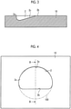
- Fig. 3 is a cross-sectional view taken along line A-A in Fig. 2 .
- Fig. 4 is a plan view illustrating a method for manufacturing the stress reduction structure according to the present embodiment.
- Fig. 5 is a cross-sectional view taken along line B-B in Fig. 4 .
- Fig. 6 is a cross-sectional view taken along line C-C in Fig. 2 .
- Figs. 2 to 6 illustrate a part of the gas turbine casing 12 (the combustor casing 12B in particular) as a part of a cylindrical member 10 having a cylindrical shape.
- the cylindrical member 10 has a machined hole 1 for attaching an external component or the like.
- the stress reduction structure of the present embodiment is to prevent a circumferential tensile load with respect to the machined hole 1 formed in the cylindrical member 10 and reduce the stress concentration.
- recesses 2 recessed in the depth direction of the machined hole 1 are formed on the circumferential side-portions of the machined hole 1.
- the recess 2 is formed by a circular arc portion 2a where a part of an opening edge is formed in a circular arc shape (horseshoe or C shape) and an open portion 2b where the circular arc shape is open and both ends of the circular arc shape are linearly connected.
- the bottom portion of the recess 2 is formed so as to be gradually decreased in depth by an inclined surface 2c from the part along the circular arc portion 2a toward the open portion 2b side.
- the bottom portion of the recess 2 is formed such that the part along the circular arc portion 2a is deep and particularly the central portion of the circular arc portion 2a is the deepest and the bottom portion of the recess 2 is formed so as to be gradually decreased in depth toward the open portion 2b by the inclined surface 2c.
- the circular arc-shaped circular arc portion 2a is disposed toward the machined hole 1.
- the recess 2 is formed by a columnar end mill 100 used for cutting being used and machining being performed with a rotary shaft Ce inclined such that a part of the leading edge of the end mill 100 is in contact with the surface of the cylindrical member 10. Accordingly, the circular arc portion 2a, the open portion 2b, and the inclined surface 2c of the recess 2 are formed by a part of the leading edge being in contact at an angle with the surface of the cylindrical member 10. As illustrated in Figs. 3 and 5 , the inner surface of the recess 2 that is along the circular arc portion 2a is curved and smoothly formed and the inner surface is smoothly formed by the shape of the cutting blade (not illustrated) of the end mill 100. As described above, the recess 2 can be easily formed by the single end mill 100 without machining labor such as using a large number of tools and moving a tool.
- the recesses 2 recessed in the depth direction of the machined hole 1 are formed on the circumferential side-portions of the machined hole 1 formed in the cylindrical member 10. Accordingly, the tensile load that occurs in the circumferential direction of the machined hole 1 is mitigated by the recess 2, the position where the tensile load is applied is displaced in the depth direction from the opening portion of the machined hole 1, the load is prevented in the opening portion, and thus it is possible to reduce stress concentration at both axial ends la of the opening portion of the machined hole 1.
- the recess 2 acting in this manner has the circular arc portion 2a where a part of the opening edge is formed in a circular arc shape and the bottom portion is formed so as to be gradually decreased in depth by the inclined surface 2c from the part along the circular arc portion 2a toward the open portion 2b where the circular arc shape is open.
- the recess 2 can be easily formed without much machining labor by machining being performed by means of the end mill 100 and with the rotary shaft Ce inclined such that a part of the leading edge is in contact with the surface of the cylindrical member 10.
- the circular arc portion 2a having a relatively deep bottom portion is disposed toward the machined hole 1, and thus the effect of the mitigation of the tensile load occurring in the circumferential direction of the machined hole 1 can be obtained to a significant extent. As a result, it is possible to reduce the stress concentration on the machined hole 1 formed in the cylindrical member 10 while suppressing an increase in weight.
- the recess 2 is capable of obtaining the effect of the mitigation of the tensile load occurring in the circumferential direction of the machined hole 1 to a significant extent insofar as the circular arc portion 2a having a relatively deep bottom portion is disposed toward the machined hole 1.
- the open portion 2b may have the disposition illustrated in Fig. 2 , in which the open portion 2b is not disposed toward the axial direction.
- a configuration may be adopted in which the open portion 2b is disposed toward the direction opposite to the machined hole 1 in the circumferential direction.
- the inner surface of the recess 2 that is along the circular arc portion 2a is curved, smoothly formed, and continuous with the inclined surface 2c. Accordingly, it is possible to prevent tensile load application to the recess 2 itself as compared with a shape in which the inner surface has a corner.
- the recess 2 is provided on the circumferential side-portion of the machined hole 1 open on the tube inner side or the tube outer side of the cylindrical member 10 in the case of penetration by the machined hole 1.
- the recess 2 is provided on the circumferential side-portion of the machined hole 1 on the side where the machined hole 1 is open.
- a deepest depth h of the recess 2 is within the range of 50% or less of a plate thickness H of the cylindrical member 10 in which the machined hole 1 is formed.
- the position where the tensile load is applied can be displaced in the depth direction from the opening portion of the machined hole 1, the effect of load prevention in the opening portion can be obtained to a significant extent, and tensile load application to the recess 2 itself can be prevented.
- a shortest distance d1 between the recess 2 and the opening edge of the machined hole 1 is within the range of 50% or less of a diametral dimension D of the machined hole 1 in the circumferential direction.
- the effect of load prevention in the opening portion of the machined hole 1 can be obtained to a significant extent.
- a diametral dimension d2 of the recess 2 in the circumferential direction is within the range of 100% or more to 300% or less of the diametral dimension D of the machined hole 1 in the circumferential direction.
- the effect of load prevention in the opening portion of the machined hole 1 can be obtained to a significant extent by the diametral dimension d2 of the recess 2 in the circumferential direction being 100% or more of the diametral dimension D of the machined hole 1 in the circumferential direction.
- the effect of load prevention in the opening portion of the machined hole 1 can be obtained to a significant extent and a decline in the strength of the cylindrical member 10 caused by the recess 2 being provided can be suppressed by the diametral dimension d2 of the recess 2 in the circumferential direction being 300% or less of the diametral dimension D of the machined hole 1 in the circumferential direction.
- a diametral dimension w of the recess 2 in the axial direction is within the range of 100% or more to 300% or less of a diametral dimension W of the machined hole 1 in the axial direction and the dimension W of the machined hole 1 is included in the circumferential position in the range of the dimension w.
- the effect of load prevention in the opening portion of the machined hole 1 can be obtained to a significant extent by the diametral dimension w of the recess 2 in the axial direction being 100% or more of the diametral dimension W of the machined hole 1 in the axial direction and the dimension W of the machined hole 1 being included in the circumferential position in the range of the dimension w.
- the effect of load prevention in the opening portion of the machined hole 1 can be obtained to a significant extent and a decline in the strength of the cylindrical member 10 caused by the recess 2 being provided can be suppressed by the diametral dimension w of the recess 2 in the axial direction being 300% or less of the diametral dimension W of the machined hole 1 in the axial direction and the dimension W of the machined hole 1 being included in the circumferential position in the range of the dimension w.
- the recesses 2 are disposed on both circumferential side-portions of the machined hole 1.
- the recesses 2 are disposed on both circumferential side-portions of the machined hole 1 and formed in a symmetrical shape with respect to the center of the machined hole 1.
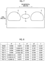
- Fig. 7 is a plan view illustrating another embodiment of the stress reduction structure according to the embodiment of the present invention.
- the machined hole 1 is formed in an elliptical shape that is long in a circumferential direction.
- the gas turbine casing 12 forms the cylindrical member 10 having the machined hole 1 and the recess 2 described above.
- the gas turbine of the present embodiment has the gas turbine casing 12 as an outer shell.
- Fig. 8 is a chart according to this example.
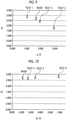
- Figs. 9 and 10 are graphs according to this example.
- Base and Tests 1 to 6 specified in Base and Tests 1 to 6 are the shortest distance d1 between the recess and the opening edge of the machined hole, the diametral dimension w of the recess in the axial direction, a dimension w1 (see Fig. 2 ) of the circular arc portion side of the recess in the axial direction from the center of the machined hole, a dimension w2 (see Fig. 2 ) of the open portion side of the recess in the axial direction from the center of the machined hole, and the deepest depth h of the recess.
- the machined hole has a perfect circle shape as illustrated in Fig.
- the recess has the circular arc portion, the open portion, and the inclined surface as illustrated in Figs. 2 and 3 and is disposed on both axial side portions of the machined hole.
- D diametral dimension
- w the diametral dimension of the recess in the axial direction
- d1 the shortest distance between the recess and the opening edge of the machined hole was changed.
- the unit of the numerical values in Fig. 8 is inch (25,4 mm).
- Each rhombus in Figs. 9 and 10 is an outer back node of the machined hole (the axial upper end 1a of the opening portion of the machined hole 1 in Fig. 2 ) and the rhombuses indicate Kt at the nodes.
- Kt is a stress concentration coefficient and is the ratio of an analysis result to the theoretical stress at infinity.
Landscapes
- Engineering & Computer Science (AREA)
- Mechanical Engineering (AREA)
- General Engineering & Computer Science (AREA)
- Chemical & Material Sciences (AREA)
- Combustion & Propulsion (AREA)
- Structures Of Non-Positive Displacement Pumps (AREA)
Description
- The present invention relates to a gas turbine casing provided with a stress reduction structure, and a gas turbine engine.
- For example,
JP H05-240110 A - For example,
WO 2015/038931 A1 discloses providing packets (recesses) on both hoop-direction sides of a hole in order to reduce the hoop stress that occurs in the hole provided in a case of a gas turbine engine and the pocket having an outer edge having a circular shape including a racetrack shape and including a flat bottom portion, a curved bottom portion, or a spherical shape. -
US 2003/131603 A discloses a method and an apparatus for relieving stress in a combustion case of a gas turbine engine. The combustion case is generally cylindrical or conical and apertures penetrate the case, from the outer surface, through the case, to the inner surface. To dissipate the stress created at the apertures acting as concentration points, bosses buttress the apertures, with each aperture having one boss on the outer surface of the case, and another boss on the inner surface of the case. -
US 2003/131603 A teaches to eliminate the latter boss and to instead dissipate stress by providing an array of T-slots with a uniform depth on the inner surface of the case between adjacent apertures. -
WO 2008/035497 A1 discloses a vacuum pump for exhausting a vacuum container and a flange thereof and aims at solving the problem of alleviating an impact and a resulting stress on the flange and a vacuum vessel connected to it caused by a torque created during operation of the vacuum pump when a rotor section collides with a stationary member in the stator section and an angular momentum of the rotor section is transmitted to the stator section and the fixed member and rotates the entire vacuum pump in the direction of rotation of the rotor section. For this purpose the document teaches an impact damping structure that has grooves arranged on both sides of a bolt penetration section, or near portions on both those sides of the bolt penetration section) that lie along the circumferential direction of a flange, and also has a thin wall section formed between a groove and the bolt penetration hole. - A casing of a gas turbine engine is formed in a cylindrical shape and a high thermal stress results from the temperature difference that occurs at start and stop. In addition, the pressure inside the casing rises with operation and hoop stress, which is a circumferential tensile stress, occurs on the cylindrical shape. In such casings, machined holes for attaching external components or the like are formed. The high thermal stress and the hoop stress described above are repeatedly applied at start and stop, and thus the low-cycle fatigue life of the machined hole is significantly reduced. An increase in thickness in the vicinity of the machined hole is a general measure for hoop stress reduction around the machined hole. As for aviation gas turbines, however, the measure is not preferable from the viewpoint of suppressing an increase in weight as much as possible.
-
WO 2015/038931 A1 discloses a device for reducing the hoop stress that occurs in the hole provided in the case of the gas turbine engine as described above. - However, the flat bottom portion, the curved bottom portion, or the spherical pocket as illustrated in
WO 2015/038931 A1 has poor machinability- and high cost-related problems. - The present invention is to solve the above problems, and an object of the present invention is to provide a gas turbine casing with a stress reduction structure, and a gas turbine engine with which machining can be facilitated and stress concentration on a machined hole formed in a cylindrical member can be reduced.
- In order to achieve the above object, the present invention provides a gas turbine engine comprising a gas turbine casing with the features of
claim 1. - In the stress reduction structure, the recesses recessed in the depth direction of the machined hole are formed on the circumferential side-portions of the machined hole formed in the cylindrical member.
- Accordingly, the tensile load that occurs in the circumferential direction of the machined hole is mitigated by the recess, the position where the tensile load is applied is displaced in the depth direction from the opening portion of the machined hole, the load is prevented in the opening portion, and thus it is possible to reduce stress concentration at both axial ends of the opening portion of the machined hole. The recess acting in this manner has a part of the opening edge formed in a circular arc shape and the bottom portion is formed so as to be gradually decreased in depth by the inclined surface from the part along the circular arc shape toward the open side of the circular arc shape. Accordingly, the recess can be easily formed without much machining labor by machining being performed by means of a tool such as an end mill and with a rotary shaft inclined such that a part of a leading edge is in contact with the surface of the cylindrical member. In the recess formed in such a shape, the circular arc-shaped part having a relatively deep bottom portion is disposed toward the machined hole, and thus the effect of the mitigation of the tensile load occurring in the circumferential direction of the machined hole can be obtained to a significant extent. As a result, it is possible to reduce the stress concentration on the machined hole formed in the cylindrical member while suppressing an increase in weight.
- In the stress reduction structure, the recess has a deepest depth h within a range of 50% or less of a plate thickness H of the cylindrical member in which the machined hole is formed.
- By the deepest depth h of the recess being 50% or less of the plate thickness H of the cylindrical member in which the machined hole is formed in the stress reduction structure, the position where the tensile load is applied can be displaced in the depth direction from the opening portion of the machined hole, the effect of load prevention in the opening portion can be obtained to a significant extent, and tensile load application to the recess itself can be prevented.
- In the stress reduction structure, the recess has a shortest distance d1 to an opening edge of the machined hole within a range of 50% or less of a circumferential diametral dimension D of the machined hole.
- By the shortest distance d1 of the recess being 50% or less of the circumferential diametral dimension D of the machined hole in the stress reduction structure, the effect of load prevention in the opening portion of the machined hole can be obtained to a significant extent.
- In the stress reduction structure, a circumferential diametral dimension d2 of the recess is within a range of 100% or more to 300% or less of a circumferential diametral dimension D of the machined hole.
- The effect of load prevention in the opening portion of the machined hole can be obtained to a significant extent by the circumferential diametral dimension d2 of the recess being 100% or more of the circumferential diametral dimension D of the machined hole in the stress reduction structure. The effect of load prevention in the opening portion of the machined hole can be obtained to a significant extent and a decline in the strength of the cylindrical member caused by the recess being provided can be suppressed by the circumferential diametral dimension d2 of the recess being 300% or less of the circumferential diametral dimension D of the machined hole.
- In the stress reduction structure, an axial diametral dimension w of the recess is within a range of 100% or more to 300% or less of an axial diametral dimension W of the machined hole and the dimension W of the machined hole is included in a circumferential position in the range of the dimension w.
- The effect of load prevention in the opening portion of the machined hole can be obtained to a significant extent by the axial diametral dimension w of the recess being 100% or more of the axial diametral dimension W of the machined hole and the dimension W of the machined hole being included in the circumferential position in the range of the dimension w in the stress reduction structure. The effect of load prevention in the opening portion of the machined hole can be obtained to a significant extent and a decline in the strength of the cylindrical member caused by the recess being provided can be suppressed by the axial diametral dimension w of the recess being 300% or less of the axial diametral dimension W of the machined hole and the dimension W of the machined hole being included in the circumferential position in the range of the dimension w.
- In the stress reduction structure, it is preferable that the recesses are disposed on both circumferential side-portions of the machined hole.
- In the stress reduction structure, the action of the mitigation of the tensile load occurring on both circumferential sides of the machined hole can be obtained to a significant extent by the recesses being disposed on both circumferential side-portions of the machined hole.
- In the stress reduction structure, it is preferable that the recesses are disposed on both circumferential side-portions of the machined hole and formed in a symmetrical shape with respect to a center of the machined hole.
- In the stress reduction structure, the action of the mitigation of the tensile load occurring on both circumferential sides of the machined hole can be obtained to a significant extent and equally on both circumferential sides by the recesses being disposed on both circumferential side-portions of the machined hole and formed in a symmetrical shape with respect to the center of the machined hole.
- In the stress reduction structure, it is preferable that the machined hole is formed in an elliptical shape that is long in a circumferential direction.
- In the stress reduction structure, the curvature at both axial ends where stress concentrates is larger than in the case of a circular shape by the machined hole being formed in an elliptical shape that is long in a circumferential direction, and thus the stress is easily dispersed in the circumferential direction of both ends. As a result, it is possible to reduce the stress concentration at both axial ends of the opening portion of the machined hole in synergy with the effect of the recess.
- With the gas turbine casing according to the invention, it is possible to prevent a decline in low-cycle fatigue life based on the machined hole in the case of high thermal stress or hoop stress occurrence.
- In order to achieve the above object, a gas turbine engine according to an embodiment of the present invention includes the gas turbine casing described above as an outer shell.
- With the gas turbine engine, a decline in low-cycle fatigue life is prevented in the gas turbine casing, and thus life extension and reliability improvement can be achieved. Advantageous Effects of Invention
- With the present invention, it is possible to facilitate machining and reduces stress concentration on a machined hole formed in a cylindrical member.
-
-
Fig. 1 is a schematic configuration diagram of a gas turbine engine according to an embodiment of the present invention. -
Fig. 2 is a plan view of a stress reduction structure according to the embodiment of the present invention. -
Fig. 3 is a cross-sectional view taken along line A-A inFig. 2 . -
Fig. 4 is a plan view illustrating a method for manufacturing the stress reduction structure according to the embodiment of the present invention. -
Fig. 5 is a cross-sectional view taken along line B-B inFig. 4 . -
Fig. 6 is a cross-sectional view taken along line C-C inFig. 2 . -
Fig. 7 is a plan view illustrating another embodiment of the stress reduction structure according to the embodiment of the present invention. -
Fig. 8 is a chart according to an example of the present invention. -
Fig. 9 is a graph according to the example of the present invention. -
Fig. 10 is a graph according to the example of the present invention. - Hereinafter, an embodiment according to the present invention will be described in detail based on the drawings.
-
Fig. 1 is a schematic configuration diagram of a gas turbine engine according to the present embodiment. - The gas turbine engine illustrated in
Fig. 1 is an aviation gas turbine. The aviation gas turbine has afan casing 11 and agas turbine casing 12. Afan 13 is accommodated in thefan casing 11. Thegas turbine casing 12 is formed in a cylindrical shape with acompressor casing 12A, acombustor casing 12B, and aturbine casing 12C continuously disposed. Acompressor 14 is accommodated in thecompressor casing 12A, acombustor 15 is accommodated in thecombustor casing 12B, and aturbine 16 is accommodated in theturbine casing 12C. - The
fan 13 is configured by a plurality offan blades 22 being mounted on the outer peripheral portion of arotary shaft 21. Thecompressor 14 has a low-pressure compressor 23 and a high-pressure compressor 24. A plurality of thecombustors 15 are positioned downstream of thecompressor 14 and disposed in a circumferential direction. Theturbine 16 is positioned downstream of thecombustor 15 and has a high-pressure turbine 25 and a low-pressure turbine 26. Therotary shaft 21 of thefan 13 and the low-pressure compressor 23 are connected, and the low-pressure compressor 23 and the low-pressure turbine 26 are connected by afirst rotor shaft 27. The high-pressure compressor 24 and the high-pressure turbine 25 are connected by a cylindricalsecond rotor shaft 28 positioned on the outer periphery side of thefirst rotor shaft 27. - Accordingly, in the
compressor 14, air taken in from an air intake port becomes high-temperature and high-pressure compressed air by being compressed through a plurality of stator and rotor vanes (not illustrated) in the low-pressure compressor 23 and the high-pressure compressor 24. In thecombustor 15, combustion is performed by a predetermined fuel being supplied to the compressed air. The high-temperature and high-pressure combustion gas that is a working fluid generated in the combustor 15 passes through a plurality of stator and rotor vanes (not illustrated) in the high-pressure turbine 25 and the low-pressure turbine 26 constituting theturbine 16, and thefirst rotor shaft 27 and thesecond rotor shaft 28 are driven to rotate as a result. In this case, driving is performed by the rotational force of the low-pressure turbine 26 being transmitted to the low-pressure compressor 23 by thefirst rotor shaft 27. In addition, driving is performed by the rotational force of the high-pressure turbine 25 being transmitted to the high-pressure compressor 24 by thesecond rotor shaft 28. As a result, thefan 13 can be driven and thrust can be obtained by means of the exhaust gas discharged from theturbine 16. - The gas turbine engine according to the present embodiment is not limited to the aviation gas turbine described above and includes, for example, a power generation gas turbine.
- The stress reduction structure according to the present embodiment is applied to the
gas turbine casing 12 in the gas turbine as described above. Thegas turbine casing 12 is formed in a cylindrical shape as described above, and a high thermal stress results from the temperature difference that occurs when the gas turbine is started or stopped. In addition, the pressure inside thegas turbine casing 12 rises with operation and hoop stress, which is a circumferential tensile stress, occurs on the cylindrical shape. The high thermal stress and the hoop stress occur particularly in thecombustor casing 12B generating a combustion gas. Here, the circumferential direction refers to a circumferential direction around an axial center R, which is the center of rotation of thefirst rotor shaft 27 and thesecond rotor shaft 28 inFig. 1 . The axial direction in the following description refers to a direction parallel to the axial center R. -
Fig. 2 is a plan view of the stress reduction structure according to the present embodiment.Fig. 3 is a cross-sectional view taken along line A-A inFig. 2 .Fig. 4 is a plan view illustrating a method for manufacturing the stress reduction structure according to the present embodiment.Fig. 5 is a cross-sectional view taken along line B-B inFig. 4 .Fig. 6 is a cross-sectional view taken along line C-C inFig. 2 . -
Figs. 2 to 6 illustrate a part of the gas turbine casing 12 (thecombustor casing 12B in particular) as a part of acylindrical member 10 having a cylindrical shape. Thecylindrical member 10 has a machinedhole 1 for attaching an external component or the like. - In the
machined hole 1, the high thermal stress and the hoop stress described above are repeatedly applied at start and stop, and thus a tensile load in the circumferential direction inFig. 2 causes stress concentration at both axial ends la of an opening portion, which results in a significant reduction in the low-cycle fatigue life of thecylindrical member 10. Accordingly, the stress reduction structure of the present embodiment is to prevent a circumferential tensile load with respect to the machinedhole 1 formed in thecylindrical member 10 and reduce the stress concentration. - In the stress reduction structure of the present embodiment, recesses 2 recessed in the depth direction of the machined
hole 1 are formed on the circumferential side-portions of the machinedhole 1. As illustrated inFig. 2 , therecess 2 is formed by acircular arc portion 2a where a part of an opening edge is formed in a circular arc shape (horseshoe or C shape) and anopen portion 2b where the circular arc shape is open and both ends of the circular arc shape are linearly connected. In addition, as illustrated inFig. 3 , the bottom portion of therecess 2 is formed so as to be gradually decreased in depth by aninclined surface 2c from the part along thecircular arc portion 2a toward theopen portion 2b side. In other words, the bottom portion of therecess 2 is formed such that the part along thecircular arc portion 2a is deep and particularly the central portion of thecircular arc portion 2a is the deepest and the bottom portion of therecess 2 is formed so as to be gradually decreased in depth toward theopen portion 2b by theinclined surface 2c. In therecess 2, the circular arc-shapedcircular arc portion 2a is disposed toward themachined hole 1. - As illustrated in
Figs. 4 and5 , therecess 2 is formed by acolumnar end mill 100 used for cutting being used and machining being performed with a rotary shaft Ce inclined such that a part of the leading edge of theend mill 100 is in contact with the surface of thecylindrical member 10. Accordingly, thecircular arc portion 2a, theopen portion 2b, and theinclined surface 2c of therecess 2 are formed by a part of the leading edge being in contact at an angle with the surface of thecylindrical member 10. As illustrated inFigs. 3 and5 , the inner surface of therecess 2 that is along thecircular arc portion 2a is curved and smoothly formed and the inner surface is smoothly formed by the shape of the cutting blade (not illustrated) of theend mill 100. As described above, therecess 2 can be easily formed by thesingle end mill 100 without machining labor such as using a large number of tools and moving a tool. - In the stress reduction structure of the present embodiment, the
recesses 2 recessed in the depth direction of the machinedhole 1 are formed on the circumferential side-portions of the machinedhole 1 formed in thecylindrical member 10. Accordingly, the tensile load that occurs in the circumferential direction of the machinedhole 1 is mitigated by therecess 2, the position where the tensile load is applied is displaced in the depth direction from the opening portion of the machinedhole 1, the load is prevented in the opening portion, and thus it is possible to reduce stress concentration at both axial ends la of the opening portion of the machinedhole 1. Therecess 2 acting in this manner has thecircular arc portion 2a where a part of the opening edge is formed in a circular arc shape and the bottom portion is formed so as to be gradually decreased in depth by theinclined surface 2c from the part along thecircular arc portion 2a toward theopen portion 2b where the circular arc shape is open. As described above, therecess 2 can be easily formed without much machining labor by machining being performed by means of theend mill 100 and with the rotary shaft Ce inclined such that a part of the leading edge is in contact with the surface of thecylindrical member 10. In therecess 2 formed in such a shape, thecircular arc portion 2a having a relatively deep bottom portion is disposed toward themachined hole 1, and thus the effect of the mitigation of the tensile load occurring in the circumferential direction of the machinedhole 1 can be obtained to a significant extent. As a result, it is possible to reduce the stress concentration on themachined hole 1 formed in thecylindrical member 10 while suppressing an increase in weight. - The
recess 2 is capable of obtaining the effect of the mitigation of the tensile load occurring in the circumferential direction of the machinedhole 1 to a significant extent insofar as thecircular arc portion 2a having a relatively deep bottom portion is disposed toward themachined hole 1. Accordingly, theopen portion 2b may have the disposition illustrated inFig. 2 , in which theopen portion 2b is not disposed toward the axial direction. For example, a configuration may be adopted in which theopen portion 2b is disposed toward the direction opposite to the machinedhole 1 in the circumferential direction. - The inner surface of the
recess 2 that is along thecircular arc portion 2a is curved, smoothly formed, and continuous with theinclined surface 2c. Accordingly, it is possible to prevent tensile load application to therecess 2 itself as compared with a shape in which the inner surface has a corner. - The
recess 2 is provided on the circumferential side-portion of the machinedhole 1 open on the tube inner side or the tube outer side of thecylindrical member 10 in the case of penetration by the machinedhole 1. In the case of non-penetration by the machinedhole 1, therecess 2 is provided on the circumferential side-portion of the machinedhole 1 on the side where the machinedhole 1 is open. - As illustrated in
Figs. 5 and 6 , in the stress reduction structure of the present embodiment, a deepest depth h of therecess 2 is within the range of 50% or less of a plate thickness H of thecylindrical member 10 in which the machinedhole 1 is formed. - By the deepest depth h of the
recess 2 being 50% or less of the plate thickness H of thecylindrical member 10 in which the machinedhole 1 is formed, the position where the tensile load is applied can be displaced in the depth direction from the opening portion of the machinedhole 1, the effect of load prevention in the opening portion can be obtained to a significant extent, and tensile load application to therecess 2 itself can be prevented. - As illustrated in
Figs. 2 and6 , in the stress reduction structure of the present embodiment, a shortest distance d1 between therecess 2 and the opening edge of the machinedhole 1 is within the range of 50% or less of a diametral dimension D of the machinedhole 1 in the circumferential direction. - By the shortest distance d1 of the
recess 2 being 50% or less of the diametral dimension D of the machinedhole 1 in the circumferential direction, the effect of load prevention in the opening portion of the machinedhole 1 can be obtained to a significant extent. - As illustrated in
Fig. 2 , in the stress reduction structure of the present embodiment, a diametral dimension d2 of therecess 2 in the circumferential direction is within the range of 100% or more to 300% or less of the diametral dimension D of the machinedhole 1 in the circumferential direction. - The effect of load prevention in the opening portion of the machined
hole 1 can be obtained to a significant extent by the diametral dimension d2 of therecess 2 in the circumferential direction being 100% or more of the diametral dimension D of the machinedhole 1 in the circumferential direction. The effect of load prevention in the opening portion of the machinedhole 1 can be obtained to a significant extent and a decline in the strength of thecylindrical member 10 caused by therecess 2 being provided can be suppressed by the diametral dimension d2 of therecess 2 in the circumferential direction being 300% or less of the diametral dimension D of the machinedhole 1 in the circumferential direction. - As illustrated in
Fig. 2 , in the stress reduction structure of the present embodiment, a diametral dimension w of therecess 2 in the axial direction is within the range of 100% or more to 300% or less of a diametral dimension W of the machinedhole 1 in the axial direction and the dimension W of the machinedhole 1 is included in the circumferential position in the range of the dimension w. - The effect of load prevention in the opening portion of the machined
hole 1 can be obtained to a significant extent by the diametral dimension w of therecess 2 in the axial direction being 100% or more of the diametral dimension W of the machinedhole 1 in the axial direction and the dimension W of the machinedhole 1 being included in the circumferential position in the range of the dimension w. The effect of load prevention in the opening portion of the machinedhole 1 can be obtained to a significant extent and a decline in the strength of thecylindrical member 10 caused by therecess 2 being provided can be suppressed by the diametral dimension w of therecess 2 in the axial direction being 300% or less of the diametral dimension W of the machinedhole 1 in the axial direction and the dimension W of the machinedhole 1 being included in the circumferential position in the range of the dimension w. - As illustrated in
Fig. 2 , in the stress reduction structure of the present embodiment, it is preferable that therecesses 2 are disposed on both circumferential side-portions of the machinedhole 1. - Although the above-described effects can be obtained even with the
recess 2 disposed on one circumferential side-portion of the machinedhole 1, the action of the mitigation of the tensile load occurring on both circumferential sides of the machinedhole 1 can be obtained to a significant extent by therecesses 2 being disposed on both circumferential side-portions of the machinedhole 1. - As illustrated in
Fig. 2 , in the stress reduction structure of the present embodiment, it is preferable that therecesses 2 are disposed on both circumferential side-portions of the machinedhole 1 and formed in a symmetrical shape with respect to the center of the machinedhole 1. - Although the above-described effects can be obtained even with the
recess 2 disposed on one circumferential side-portion of the machinedhole 1 and formed asymmetrically with respect to the center of the machinedhole 1, the action of the mitigation of the tensile load occurring on both circumferential sides of the machinedhole 1 can be obtained to a significant extent and equally on both sides in the circumferential direction by therecesses 2 being disposed on both circumferential side-portions of the machinedhole 1 and formed in a symmetrical shape with respect to the center of the machinedhole 1. -
Fig. 7 is a plan view illustrating another embodiment of the stress reduction structure according to the embodiment of the present invention. - As illustrated in
Fig. 7 , in the stress reduction structure of the present embodiment, it is preferable that themachined hole 1 is formed in an elliptical shape that is long in a circumferential direction. - Although the above-described effects can be obtained even with the
machined hole 1 formed in a perfect circle shape as illustrated inFig. 2 , the curvature at bothaxial ends 1a where stress concentrates is larger than in the case of a circular shape by the machinedhole 1 being formed in an elliptical shape that is long in a circumferential direction, and thus the stress is easily dispersed in the circumferential direction of bothends 1a. As a result, it is possible to reduce the stress concentration at bothaxial ends 1a of the opening portion of the machinedhole 1 in synergy with the effect of therecess 2. - According to the invention, the
gas turbine casing 12 forms thecylindrical member 10 having the machinedhole 1 and therecess 2 described above. - With the
gas turbine casing 12, it is possible to prevent a decline in low-cycle fatigue life based on themachined hole 1 in the case of high thermal stress or hoop stress occurrence. - It is preferable that the gas turbine of the present embodiment has the
gas turbine casing 12 as an outer shell. - With the gas turbine, a decline in low-cycle fatigue life is prevented in the
gas turbine casing 12, and thus life extension and reliability improvement can be achieved. - An example will be described below.
Fig. 8 is a chart according to this example.Figs. 9 and 10 are graphs according to this example. - In this example, three-dimensional static structural analysis was performed with regard to Base and Tests 1 to 6. As illustrated in
Fig. 8 , specified in Base and Tests 1 to 6 are the shortest distance d1 between the recess and the opening edge of the machined hole, the diametral dimension w of the recess in the axial direction, a dimension w1 (seeFig. 2 ) of the circular arc portion side of the recess in the axial direction from the center of the machined hole, a dimension w2 (seeFig. 2 ) of the open portion side of the recess in the axial direction from the center of the machined hole, and the deepest depth h of the recess. The machined hole has a perfect circle shape as illustrated inFig. 2 and has the same diametral dimension D (0.26) in Base and Tests 1 to 6. The recess has the circular arc portion, the open portion, and the inclined surface as illustrated inFigs. 2 and3 and is disposed on both axial side portions of the machined hole. In Tests 1 to 3, the diametral dimension w of the recess in the axial direction was changed. In Tests 4 to 6, the shortest distance d1 between the recess and the opening edge of the machined hole was changed. The unit of the numerical values inFig. 8 is inch (25,4 mm). - Each rhombus in
Figs. 9 and 10 is an outer back node of the machined hole (the axialupper end 1a of the opening portion of the machinedhole 1 inFig. 2 ) and the rhombuses indicate Kt at the nodes. Kt is a stress concentration coefficient and is the ratio of an analysis result to the theoretical stress at infinity. - As illustrated in
Fig. 9 , inTests 1 to 3, it can be seen that Kt decreases by nearly 20% in the case of w=2D and nearly 50% in the case of w=3D with respect to w=D. Although not clearly illustrated inFig. 9 , the axiallower end 1a of the opening portion of the machinedhole 1 inFig. 2 shows a similar tendency. Accordingly, it can be seen that a stress reduction effect can be obtained by D being increased with respect to w=D. - As illustrated in
Fig. 10 , inTests 4 to 6, it can be seen that Kt decreases by nearly 10% in the case of d1=D/2 and d1=D/3 with respect to d1=D. Although not clearly illustrated inFig. 10 , the axial lower end la of the opening portion of the machinedhole 1 inFig. 2 shows a similar tendency. Accordingly, it can be seen that a stress reduction effect can be obtained by D being increased with respect to d1=D. -
- 1
- Machined hole
- 1a
- Axial end
- 2
- Recess
- 2a
- Circular arc portion
- 2b
- Open portion
- 2c
- Inclined surface
- 10
- Cylindrical member
- 12
- Gas turbine casing
Claims (6)
- A gas turbine engine comprising a gas turbine casing (12) forming a cylindrical member (10) which extends in a substantially axial direction and in a circumferential direction, the axial direction being a direction parallel to an axial center (R) which is a center of rotation of a first and second rotor shaft (27,28) of the gas turbine engine, and the circumferential direction being around the axial center (R),wherein the cylindrical member (10) has a machined hole (1) for attaching an external component and a stress reduction structure for preventing a circumferential tensile load with respect to the machined hole (1) and reducing a stress concentration due to high thermal stress and hoop stress repeatedly applied at start and stop of the gas turbine engine, andwherein the stress reduction structure comprises a recess (2) provided on a radial inner or outer side of the cylindrical member (10) where the machined hole (1) is open and formed on a circumferential side-portion of the machined hole (1) the recess (2) having a distance (d1) to an opening edge of the machined hole (1) formed in the cylindrical member (10) and being recessed in a depth direction of the machined hole (1),characterized in thatthe recess (2) is formed by a columnar end mill (100) having its rotary shaft (Ce) inclined such that a part of a leading edge of the end mill (100) is in contact at an angle with a surface of the cylindrical member (10) for defining a circular arc portion (2a) where a part of an opening edge is formed in a circular arc shape, an open portion (2b) where the circular arc shape is open and a part of the opening edge is formed by both ends of the open portion (2b) being linearly connected, and an inclined surface (2c), wherein a bottom portion of the recess (2) is formed so as to be gradually decreased in depth by the inclined surface (2c) from a central portion of the circular arc portion (2a) which is the deepest part of the recess (2) along the circular arc portion (2a) toward the linear side of the open portion (2b), and a side of the circular arc portion (2a) having a relatively deep bottom portion is disposed facing toward the machined hole (1),wherein the recess (2) has a deepest depth (h) at the central portion of the circular arc portion (2a) within a range of 50% or less of a plate thickness (H) of the cylindrical member (10) in the radial direction in which the machined hole (1) is formed,wherein the shortest distance (d1) between the opening edge of the recess (2) and the opening edge of the machined hole (1) is within a range of 50% or less of a circumferential diametral dimension (D) of the machined hole (1),wherein a circumferential diametral dimension (d2) of the recess (2) is within a range of 100% or more to 300% or less of the circumferential diametral dimension (D) of the machined hole (1), andwherein an axial diametral dimension (w) of the recess (2) is within a range of 100% or more to 300% or less of an axial diametral dimension (W) of the machined hole (1) and the axial diametral dimension (W) of the machined hole (1) is included in a circumferential position in the range of the axial diametral dimension (w) of the recess (2).
- The gas turbine engine according to Claim 1, wherein the recess (2) is respectively disposed on each of both side-portions of the machined hole (1) in the circumferential direction of the cylindrical member (10).
- The gas turbine engine according to Claim 2, wherein the recesses (2) and recess shapes are formed mirror symmetrically with respect to a center of the machined hole (1) .
- The gas turbine engine according to any one of Claims 1 to 3, wherein the machined hole (1) is formed in an elliptical shape that is long in the circumferential direction of the cylindrical member (10).
- The gas turbine engine according to any one of Claims 1 to 4, wherein the gas turbine casing (12) is an outer shell.
- The gas turbine engine according to claim 5, wherein the gas turbine engine is an aviation gas turbine engine or a power generation gas turbine engine.
Applications Claiming Priority (2)
| Application Number | Priority Date | Filing Date | Title |
|---|---|---|---|
| JP2017121293A JP6800813B2 (en) | 2017-06-21 | 2017-06-21 | Stress reduction structure, gas turbine casing and gas turbine |
| PCT/JP2018/014929 WO2018235394A1 (en) | 2017-06-21 | 2018-04-09 | Stress reduction structure, gas turbine casing and gas turbine |
Publications (3)
| Publication Number | Publication Date |
|---|---|
| EP3643903A1 EP3643903A1 (en) | 2020-04-29 |
| EP3643903A4 EP3643903A4 (en) | 2020-12-23 |
| EP3643903B1 true EP3643903B1 (en) | 2022-02-23 |
Family
ID=64735670
Family Applications (1)
| Application Number | Title | Priority Date | Filing Date |
|---|---|---|---|
| EP18819966.5A Active EP3643903B1 (en) | 2017-06-21 | 2018-04-09 | Stress reduction structure in a gas turbine casing, and gas turbine engine |
Country Status (5)
| Country | Link |
|---|---|
| US (1) | US11168586B2 (en) |
| EP (1) | EP3643903B1 (en) |
| JP (1) | JP6800813B2 (en) |
| CA (1) | CA3066209C (en) |
| WO (1) | WO2018235394A1 (en) |
Family Cites Families (16)
| Publication number | Priority date | Publication date | Assignee | Title |
|---|---|---|---|---|
| US3661045A (en) | 1970-09-17 | 1972-05-09 | Tyco Lab | Apparatus for stabilizing a rotary saw blade |
| JPH0345449U (en) * | 1989-09-11 | 1991-04-26 | ||
| JPH05240110A (en) | 1992-02-28 | 1993-09-17 | Suzuki Motor Corp | Internal combustion engine pistons |
| US5485723A (en) * | 1994-04-29 | 1996-01-23 | United Technologies Corporation | Variable thickness isogrid case |
| GB2296039A (en) | 1994-12-16 | 1996-06-19 | Perkins Ltd | Stress reduction at a high pressure fluid passage junction |
| US6237344B1 (en) * | 1998-07-20 | 2001-05-29 | General Electric Company | Dimpled impingement baffle |
| GB2364554B (en) | 2000-07-07 | 2004-04-07 | Alstom Power Nv | Turbine disc |
| JP2003075489A (en) * | 2001-09-07 | 2003-03-12 | Communication Research Laboratory | Antenna power measurement method in radio equipment and electric wave used for the method |
| US6681577B2 (en) * | 2002-01-16 | 2004-01-27 | General Electric Company | Method and apparatus for relieving stress in a combustion case in a gas turbine engine |
| JP5137365B2 (en) | 2006-09-20 | 2013-02-06 | エドワーズ株式会社 | Vacuum pump and flange |
| US8403645B2 (en) * | 2009-09-16 | 2013-03-26 | United Technologies Corporation | Turbofan flow path trenches |
| US9157328B2 (en) | 2010-12-24 | 2015-10-13 | Rolls-Royce North American Technologies, Inc. | Cooled gas turbine engine component |
| CN104204600A (en) | 2012-03-23 | 2014-12-10 | 日本发条株式会社 | Disc spring |
| WO2015038931A1 (en) | 2013-09-13 | 2015-03-19 | United Technologies Corporation | Shielding pockets for case holes |
| EP3967854B1 (en) * | 2013-11-25 | 2023-07-05 | Raytheon Technologies Corporation | Assembly for a turbine engine |
| WO2015130381A2 (en) | 2013-12-20 | 2015-09-03 | United Technologies Corporation | A gas turbine engine integrally bladed rotor with asymmetrical trench fillets |
-
2017
- 2017-06-21 JP JP2017121293A patent/JP6800813B2/en active Active
-
2018
- 2018-04-09 US US16/623,434 patent/US11168586B2/en active Active
- 2018-04-09 EP EP18819966.5A patent/EP3643903B1/en active Active
- 2018-04-09 WO PCT/JP2018/014929 patent/WO2018235394A1/en not_active Ceased
- 2018-04-09 CA CA3066209A patent/CA3066209C/en active Active
Also Published As
| Publication number | Publication date |
|---|---|
| JP2019007368A (en) | 2019-01-17 |
| WO2018235394A1 (en) | 2018-12-27 |
| CA3066209A1 (en) | 2018-12-27 |
| US11168586B2 (en) | 2021-11-09 |
| CA3066209C (en) | 2023-03-07 |
| JP6800813B2 (en) | 2020-12-16 |
| EP3643903A1 (en) | 2020-04-29 |
| US20200109647A1 (en) | 2020-04-09 |
| EP3643903A4 (en) | 2020-12-23 |
Similar Documents
| Publication | Publication Date | Title |
|---|---|---|
| US9879544B2 (en) | Turbine rotor blades with improved tip portion cooling holes | |
| US10066639B2 (en) | Compressor assembly having a vaneless space | |
| EP2971693B1 (en) | Gas turbine engine rotor disk-seal arrangement | |
| EP3139003B1 (en) | Damper pin for turbine blades and corresponding turbine engine | |
| EP3139001B1 (en) | Damper pin for turbine blades and corresponding turbine engine | |
| EP3039249B1 (en) | Mateface surfaces having a geometry on turbomachinery hardware | |
| WO2013130570A1 (en) | Turbine engine rotor blade groove | |
| EP3139002A1 (en) | Damper pin for turbine blades and corresponding turbine engine | |
| US20160265549A1 (en) | Compressor assembly having dynamic diffuser ring retention | |
| JPH02238102A (en) | Vibration damping cascade for gas turbine engine | |
| US20200157960A1 (en) | Labyrinth seal with variable tooth heights | |
| US7118346B2 (en) | Compressor blade | |
| JP7196120B2 (en) | turbine wheel | |
| EP3643903B1 (en) | Stress reduction structure in a gas turbine casing, and gas turbine engine | |
| US10584597B2 (en) | Variable cross-section damper pin for a turbine blade | |
| EP3372786B1 (en) | High-pressure compressor rotor blade with leading edge having indent segment | |
| US20170191366A1 (en) | Slotted damper pin for a turbine blade | |
| US20250109691A1 (en) | Turbine | |
| KR102808784B1 (en) | Sealing devices and rotating machines | |
| EP1443179A2 (en) | A rotor and a retaining plate for the same | |
| EP3550111B1 (en) | Turbine blade shroud for gas turbine engine with power turbine and method of manufacturing same | |
| JP7774176B1 (en) | Turbine vanes, turbines, and gas turbines | |
| US11814984B2 (en) | Rotor and compressor | |
| EP4553282A1 (en) | Turbine engine having an airfoil with cooling holes | |
| US11873733B2 (en) | Turbine blade in gas turbine engine |
Legal Events
| Date | Code | Title | Description |
|---|---|---|---|
| STAA | Information on the status of an ep patent application or granted ep patent |
Free format text: STATUS: THE INTERNATIONAL PUBLICATION HAS BEEN MADE |
|
| PUAI | Public reference made under article 153(3) epc to a published international application that has entered the european phase |
Free format text: ORIGINAL CODE: 0009012 |
|
| STAA | Information on the status of an ep patent application or granted ep patent |
Free format text: STATUS: REQUEST FOR EXAMINATION WAS MADE |
|
| 17P | Request for examination filed |
Effective date: 20191219 |
|
| AK | Designated contracting states |
Kind code of ref document: A1 Designated state(s): AL AT BE BG CH CY CZ DE DK EE ES FI FR GB GR HR HU IE IS IT LI LT LU LV MC MK MT NL NO PL PT RO RS SE SI SK SM TR |
|
| REG | Reference to a national code |
Ref country code: DE Ref legal event code: R079 Ref document number: 602018031355 Country of ref document: DE Free format text: PREVIOUS MAIN CLASS: F02C0007000000 Ipc: F01D0025240000 |
|
| A4 | Supplementary search report drawn up and despatched |
Effective date: 20201120 |
|
| RIC1 | Information provided on ipc code assigned before grant |
Ipc: F01D 25/24 20060101AFI20201116BHEP Ipc: F23R 3/00 20060101ALI20201116BHEP |
|
| STAA | Information on the status of an ep patent application or granted ep patent |
Free format text: STATUS: EXAMINATION IS IN PROGRESS |
|
| 17Q | First examination report despatched |
Effective date: 20210713 |
|
| GRAP | Despatch of communication of intention to grant a patent |
Free format text: ORIGINAL CODE: EPIDOSNIGR1 |
|
| STAA | Information on the status of an ep patent application or granted ep patent |
Free format text: STATUS: GRANT OF PATENT IS INTENDED |
|
| INTG | Intention to grant announced |
Effective date: 20211105 |
|
| GRAS | Grant fee paid |
Free format text: ORIGINAL CODE: EPIDOSNIGR3 |
|
| GRAA | (expected) grant |
Free format text: ORIGINAL CODE: 0009210 |
|
| STAA | Information on the status of an ep patent application or granted ep patent |
Free format text: STATUS: THE PATENT HAS BEEN GRANTED |
|
| AK | Designated contracting states |
Kind code of ref document: B1 Designated state(s): AL AT BE BG CH CY CZ DE DK EE ES FI FR GB GR HR HU IE IS IT LI LT LU LV MC MK MT NL NO PL PT RO RS SE SI SK SM TR |
|
| REG | Reference to a national code |
Ref country code: GB Ref legal event code: FG4D |
|
| REG | Reference to a national code |
Ref country code: CH Ref legal event code: EP |
|
| REG | Reference to a national code |
Ref country code: DE Ref legal event code: R096 Ref document number: 602018031355 Country of ref document: DE |
|
| REG | Reference to a national code |
Ref country code: AT Ref legal event code: REF Ref document number: 1470618 Country of ref document: AT Kind code of ref document: T Effective date: 20220315 |
|
| REG | Reference to a national code |
Ref country code: IE Ref legal event code: FG4D |
|
| REG | Reference to a national code |
Ref country code: LT Ref legal event code: MG9D |
|
| REG | Reference to a national code |
Ref country code: NL Ref legal event code: MP Effective date: 20220223 |
|
| REG | Reference to a national code |
Ref country code: AT Ref legal event code: MK05 Ref document number: 1470618 Country of ref document: AT Kind code of ref document: T Effective date: 20220223 |
|
| PG25 | Lapsed in a contracting state [announced via postgrant information from national office to epo] |
Ref country code: SE Free format text: LAPSE BECAUSE OF FAILURE TO SUBMIT A TRANSLATION OF THE DESCRIPTION OR TO PAY THE FEE WITHIN THE PRESCRIBED TIME-LIMIT Effective date: 20220223 Ref country code: RS Free format text: LAPSE BECAUSE OF FAILURE TO SUBMIT A TRANSLATION OF THE DESCRIPTION OR TO PAY THE FEE WITHIN THE PRESCRIBED TIME-LIMIT Effective date: 20220223 Ref country code: PT Free format text: LAPSE BECAUSE OF FAILURE TO SUBMIT A TRANSLATION OF THE DESCRIPTION OR TO PAY THE FEE WITHIN THE PRESCRIBED TIME-LIMIT Effective date: 20220623 Ref country code: NO Free format text: LAPSE BECAUSE OF FAILURE TO SUBMIT A TRANSLATION OF THE DESCRIPTION OR TO PAY THE FEE WITHIN THE PRESCRIBED TIME-LIMIT Effective date: 20220523 Ref country code: NL Free format text: LAPSE BECAUSE OF FAILURE TO SUBMIT A TRANSLATION OF THE DESCRIPTION OR TO PAY THE FEE WITHIN THE PRESCRIBED TIME-LIMIT Effective date: 20220223 Ref country code: LT Free format text: LAPSE BECAUSE OF FAILURE TO SUBMIT A TRANSLATION OF THE DESCRIPTION OR TO PAY THE FEE WITHIN THE PRESCRIBED TIME-LIMIT Effective date: 20220223 Ref country code: HR Free format text: LAPSE BECAUSE OF FAILURE TO SUBMIT A TRANSLATION OF THE DESCRIPTION OR TO PAY THE FEE WITHIN THE PRESCRIBED TIME-LIMIT Effective date: 20220223 Ref country code: ES Free format text: LAPSE BECAUSE OF FAILURE TO SUBMIT A TRANSLATION OF THE DESCRIPTION OR TO PAY THE FEE WITHIN THE PRESCRIBED TIME-LIMIT Effective date: 20220223 Ref country code: BG Free format text: LAPSE BECAUSE OF FAILURE TO SUBMIT A TRANSLATION OF THE DESCRIPTION OR TO PAY THE FEE WITHIN THE PRESCRIBED TIME-LIMIT Effective date: 20220523 |
|
| PG25 | Lapsed in a contracting state [announced via postgrant information from national office to epo] |
Ref country code: PL Free format text: LAPSE BECAUSE OF FAILURE TO SUBMIT A TRANSLATION OF THE DESCRIPTION OR TO PAY THE FEE WITHIN THE PRESCRIBED TIME-LIMIT Effective date: 20220223 Ref country code: LV Free format text: LAPSE BECAUSE OF FAILURE TO SUBMIT A TRANSLATION OF THE DESCRIPTION OR TO PAY THE FEE WITHIN THE PRESCRIBED TIME-LIMIT Effective date: 20220223 Ref country code: GR Free format text: LAPSE BECAUSE OF FAILURE TO SUBMIT A TRANSLATION OF THE DESCRIPTION OR TO PAY THE FEE WITHIN THE PRESCRIBED TIME-LIMIT Effective date: 20220524 Ref country code: FI Free format text: LAPSE BECAUSE OF FAILURE TO SUBMIT A TRANSLATION OF THE DESCRIPTION OR TO PAY THE FEE WITHIN THE PRESCRIBED TIME-LIMIT Effective date: 20220223 Ref country code: AT Free format text: LAPSE BECAUSE OF FAILURE TO SUBMIT A TRANSLATION OF THE DESCRIPTION OR TO PAY THE FEE WITHIN THE PRESCRIBED TIME-LIMIT Effective date: 20220223 |
|
| PG25 | Lapsed in a contracting state [announced via postgrant information from national office to epo] |
Ref country code: IS Free format text: LAPSE BECAUSE OF FAILURE TO SUBMIT A TRANSLATION OF THE DESCRIPTION OR TO PAY THE FEE WITHIN THE PRESCRIBED TIME-LIMIT Effective date: 20220623 |
|
| PG25 | Lapsed in a contracting state [announced via postgrant information from national office to epo] |
Ref country code: SM Free format text: LAPSE BECAUSE OF FAILURE TO SUBMIT A TRANSLATION OF THE DESCRIPTION OR TO PAY THE FEE WITHIN THE PRESCRIBED TIME-LIMIT Effective date: 20220223 Ref country code: SK Free format text: LAPSE BECAUSE OF FAILURE TO SUBMIT A TRANSLATION OF THE DESCRIPTION OR TO PAY THE FEE WITHIN THE PRESCRIBED TIME-LIMIT Effective date: 20220223 Ref country code: RO Free format text: LAPSE BECAUSE OF FAILURE TO SUBMIT A TRANSLATION OF THE DESCRIPTION OR TO PAY THE FEE WITHIN THE PRESCRIBED TIME-LIMIT Effective date: 20220223 Ref country code: EE Free format text: LAPSE BECAUSE OF FAILURE TO SUBMIT A TRANSLATION OF THE DESCRIPTION OR TO PAY THE FEE WITHIN THE PRESCRIBED TIME-LIMIT Effective date: 20220223 Ref country code: DK Free format text: LAPSE BECAUSE OF FAILURE TO SUBMIT A TRANSLATION OF THE DESCRIPTION OR TO PAY THE FEE WITHIN THE PRESCRIBED TIME-LIMIT Effective date: 20220223 Ref country code: CZ Free format text: LAPSE BECAUSE OF FAILURE TO SUBMIT A TRANSLATION OF THE DESCRIPTION OR TO PAY THE FEE WITHIN THE PRESCRIBED TIME-LIMIT Effective date: 20220223 |
|
| REG | Reference to a national code |
Ref country code: DE Ref legal event code: R097 Ref document number: 602018031355 Country of ref document: DE |
|
| PG25 | Lapsed in a contracting state [announced via postgrant information from national office to epo] |
Ref country code: AL Free format text: LAPSE BECAUSE OF FAILURE TO SUBMIT A TRANSLATION OF THE DESCRIPTION OR TO PAY THE FEE WITHIN THE PRESCRIBED TIME-LIMIT Effective date: 20220223 |
|
| REG | Reference to a national code |
Ref country code: CH Ref legal event code: PL |
|
| PLBE | No opposition filed within time limit |
Free format text: ORIGINAL CODE: 0009261 |
|
| STAA | Information on the status of an ep patent application or granted ep patent |
Free format text: STATUS: NO OPPOSITION FILED WITHIN TIME LIMIT |
|
| REG | Reference to a national code |
Ref country code: BE Ref legal event code: MM Effective date: 20220430 |
|
| PG25 | Lapsed in a contracting state [announced via postgrant information from national office to epo] |
Ref country code: MC Free format text: LAPSE BECAUSE OF FAILURE TO SUBMIT A TRANSLATION OF THE DESCRIPTION OR TO PAY THE FEE WITHIN THE PRESCRIBED TIME-LIMIT Effective date: 20220223 Ref country code: LU Free format text: LAPSE BECAUSE OF NON-PAYMENT OF DUE FEES Effective date: 20220409 Ref country code: LI Free format text: LAPSE BECAUSE OF NON-PAYMENT OF DUE FEES Effective date: 20220430 Ref country code: CH Free format text: LAPSE BECAUSE OF NON-PAYMENT OF DUE FEES Effective date: 20220430 |
|
| 26N | No opposition filed |
Effective date: 20221124 |
|
| PG25 | Lapsed in a contracting state [announced via postgrant information from national office to epo] |
Ref country code: SI Free format text: LAPSE BECAUSE OF FAILURE TO SUBMIT A TRANSLATION OF THE DESCRIPTION OR TO PAY THE FEE WITHIN THE PRESCRIBED TIME-LIMIT Effective date: 20220223 Ref country code: BE Free format text: LAPSE BECAUSE OF NON-PAYMENT OF DUE FEES Effective date: 20220430 |
|
| PG25 | Lapsed in a contracting state [announced via postgrant information from national office to epo] |
Ref country code: IE Free format text: LAPSE BECAUSE OF NON-PAYMENT OF DUE FEES Effective date: 20220409 |
|
| PG25 | Lapsed in a contracting state [announced via postgrant information from national office to epo] |
Ref country code: IT Free format text: LAPSE BECAUSE OF FAILURE TO SUBMIT A TRANSLATION OF THE DESCRIPTION OR TO PAY THE FEE WITHIN THE PRESCRIBED TIME-LIMIT Effective date: 20220223 |
|
| PG25 | Lapsed in a contracting state [announced via postgrant information from national office to epo] |
Ref country code: MK Free format text: LAPSE BECAUSE OF FAILURE TO SUBMIT A TRANSLATION OF THE DESCRIPTION OR TO PAY THE FEE WITHIN THE PRESCRIBED TIME-LIMIT Effective date: 20220223 Ref country code: CY Free format text: LAPSE BECAUSE OF FAILURE TO SUBMIT A TRANSLATION OF THE DESCRIPTION OR TO PAY THE FEE WITHIN THE PRESCRIBED TIME-LIMIT Effective date: 20220223 |
|
| PG25 | Lapsed in a contracting state [announced via postgrant information from national office to epo] |
Ref country code: HU Free format text: LAPSE BECAUSE OF FAILURE TO SUBMIT A TRANSLATION OF THE DESCRIPTION OR TO PAY THE FEE WITHIN THE PRESCRIBED TIME-LIMIT; INVALID AB INITIO Effective date: 20180409 |
|
| PG25 | Lapsed in a contracting state [announced via postgrant information from national office to epo] |
Ref country code: MT Free format text: LAPSE BECAUSE OF FAILURE TO SUBMIT A TRANSLATION OF THE DESCRIPTION OR TO PAY THE FEE WITHIN THE PRESCRIBED TIME-LIMIT Effective date: 20220223 |
|
| PGFP | Annual fee paid to national office [announced via postgrant information from national office to epo] |
Ref country code: DE Payment date: 20250305 Year of fee payment: 8 |
|
| PG25 | Lapsed in a contracting state [announced via postgrant information from national office to epo] |
Ref country code: TR Free format text: LAPSE BECAUSE OF FAILURE TO SUBMIT A TRANSLATION OF THE DESCRIPTION OR TO PAY THE FEE WITHIN THE PRESCRIBED TIME-LIMIT Effective date: 20220223 |
|
| PGFP | Annual fee paid to national office [announced via postgrant information from national office to epo] |
Ref country code: GB Payment date: 20260313 Year of fee payment: 9 |
|
| PGFP | Annual fee paid to national office [announced via postgrant information from national office to epo] |
Ref country code: FR Payment date: 20260309 Year of fee payment: 9 |