EP3643818B1 - Air-jet type spinning device - Google Patents
Air-jet type spinning device Download PDFInfo
- Publication number
- EP3643818B1 EP3643818B1 EP19204430.3A EP19204430A EP3643818B1 EP 3643818 B1 EP3643818 B1 EP 3643818B1 EP 19204430 A EP19204430 A EP 19204430A EP 3643818 B1 EP3643818 B1 EP 3643818B1
- Authority
- EP
- European Patent Office
- Prior art keywords
- spinning
- air
- jet type
- chamber
- spindle
- Prior art date
- Legal status (The legal status is an assumption and is not a legal conclusion. Google has not performed a legal analysis and makes no representation as to the accuracy of the status listed.)
- Active
Links
Images




Classifications
-
- D—TEXTILES; PAPER
- D01—NATURAL OR MAN-MADE THREADS OR FIBRES; SPINNING
- D01H—SPINNING OR TWISTING
- D01H4/00—Open-end spinning machines or arrangements for imparting twist to independently moving fibres separated from slivers; Piecing arrangements therefor; Covering endless core threads with fibres by open-end spinning techniques
- D01H4/02—Open-end spinning machines or arrangements for imparting twist to independently moving fibres separated from slivers; Piecing arrangements therefor; Covering endless core threads with fibres by open-end spinning techniques imparting twist by a fluid, e.g. air vortex
-
- D—TEXTILES; PAPER
- D01—NATURAL OR MAN-MADE THREADS OR FIBRES; SPINNING
- D01H—SPINNING OR TWISTING
- D01H1/00—Spinning or twisting machines in which the product is wound-up continuously
- D01H1/11—Spinning by false-twisting
- D01H1/115—Spinning by false-twisting using pneumatic means
Definitions
- the present invention relates to an air-jet type spinning device.
- air-jet type spinning devices produce the yarn production starting from a fibre web.
- This web is subjected to the action of compressed air jets which allow the outermost fibres to open and wrap around the central ones and form the yarn.
- the known solutions entail some structural limits in the implementation of the spinning chamber since the jets of compressed air must be directed in an extremely precise manner in the proximity of the tip of the spinning spindle: in other words, the jets must be directed towards the tangential direction and inclined downwards to obtain the necessary swirling of the compressed air which must, on the one hand, wrap the outer fibres around the inner ones and on the other create the necessary depression to suck the fibres inside the spinning spindle.
- 4 indicates globally an air-jet type spinning device, comprising an at least partially hollow body 8 which delimits a cylindrical spinning chamber 12.
- the body comprises at least one injection hole 16 configured to introduce a flow of compressed air into said spinning chamber 12 and thereby obtain the formation of yarn through the fibre twisting.
- the spinning device 4 comprises a fibre feeding device 20, facing said spinning chamber 12 so as to be able to feed the fibres in the spinning chamber 12.
- the fibre feeding device 20 comprises a fibre feeding channel 24 having a first straight section 28 leading, at a shoulder 32, into a pre-chamber 36 facing and communicating with said spinning chamber 12.
- the first straight section 28 of the fibre feeding channel 24, with respect to a section plane passing through a median plane M-M of the first straight section 28 and through a central axis C-C of the fibre feeding device 20, is inclined (i.e. not parallel) with respect to said central axis C-C.
- the first straight section 28, with respect to a cross-section plane passing through a median plane M-M of said first straight section 28 and a central axis C-C of the fibre feeding device 20, has a truncated-conical cross-section diverging towards the spinning chamber 12.
- said first straight section 28, with respect to a cross-section plane passing through a median plane M-M of the first straight section 28 and a central axis C-C of the fibre feeding device 20, is delimited by an external wall 40 inclined with respect to the central axis C-C by an external angle ⁇ between 2° and 3.75°.
- said first straight section 28, with respect to a cross-section plane passing through a median plane M-M of the first straight section 28 and a central axis C-C of the fibre feeding device 20, is delimited by an inner wall 44 inclined with respect to the central axis C-C by an inner angle ⁇ between 3.5° and 5.5° .
- the particular geometrical conformation of the fibre feeding channel 24 contributes to the improved formation of the yarn and to the constancy of the spinning conditions.
- the spinning device 4 further comprises a spinning spindle 48 at least partially inserted in the spinning chamber 12 and provided with a spinning channel 52 for the passage of yarn obtained from said fibres.
- the spinning channel 52 has a main axis which defines a spinning direction (X-X) and has a front inlet 56 for introducing the fibres into said spinning channel 52.
- the spinning chamber has extremely compact dimensions.
- a diameter 60 of the spinning chamber 12, measured relative to a cross-section plane perpendicular to said main axis, is between 5.6 and 7.4 mm.
- the spinning spindle 48 has an overall frusto-conical shape with a circular and axially symmetrical section with respect to said spinning direction X-X; in particular, the spinning spindle 48 tapers towards the front inlet 56.
- said spinning spindle 48 has an inlet diameter 64, at said front inlet 56, comprised between 47% and 61% of the diameter 60 of the spinning chamber 12.
- said inlet diameter 64 is between 3.2 and 3.9 mm.
- the spinning spindle 48 has a truncated cone shape, wherein an average diameter 68 of said spinning spindle, at an intermediate height of the spinning spindle 48, is equal to 1.1 - 1.3 times the inlet diameter 64 of the spinning spindle 48, at said front inlet 56.
- a bottom diameter 72 of the spinning spindle 48, on the opposite side to its front inlet 56, is equal to 1.1 - 1.3 times said average diameter 68.
- the injection hole also has a specific position with respect to the spinning chamber 12 and/or the spinning spindle 48.
- Said at least one injection hole 16 is arranged upstream of the front inlet 56 of the spinning spindle 48, along said spinning direction.
- said at least one injection hole 16 is arranged at a distance 76 from the shoulder 32 of between 2.4 and 3.5 mm.
- the distance between the at least one injection hole 16 and the front inlet 56 of the spinning channel 52, measured parallel to the spinning direction, is greater than or equal to 0.3 mm, and the injection hole 16 is arranged upstream of the front inlet 56.
- the injection hole 16 is located just upstream, i.e. above, with respect to the front inlet 56 of the spinning channel 52.
- the spinning chamber 12 has some peculiarity.
- the spinning chamber 12 is delimited at least partially by an outer side wall 80, opposite the spinning spindle 48, wherein on said outer side wall 80 at least one thread 84 is made; moreover, said at least one injection hole 16 is oriented so as to direct the jet of compressed air towards the at least one thread 84 so as to be guided and oriented by the latter.
- the thread 84 acts as a guide for the movement of the air flow inside the spinning chamber 12.
- the at least one thread 84 is a helical thread, coaxial with said spinning channel 52 and parallel to the spinning direction (X-X).
- the spinning device 4 comprises at least two injection holes 16 which direct compressed air into two distinct emission points of a same helical thread 84; said emission points are diametrically opposed to each other and send jets of compressed air in opposite directions to each other, so as to generate a synchronised motion of vorticity which triggers the twisting of the fibres in the spinning chamber 12.
- said thread 84 has a geometry with a curvilinear or semicircular section, preferably with a radius of between 0.25 mm and 2 mm.
- said thread 84 is inclined according to a helix angle of between 5° and 15°.
- the pitch of said thread 84 is between 1.5 mm and 4 mm.
- the outer side wall 80 can also comprise a plurality of threads which direct and guide as many flows of compressed air.
- the fibre feeding device 20 comprises a needle 88, at least partially penetrated in said spinning chamber 12 and axially opposite said front inlet 56, so as to create a guide for the fibres being spun.
- the air-jet type spinning device according to the invention allows the drawbacks of the prior art to be overcome.
- the present invention can lead to a reduction in air consumption with respect to the solutions of the prior art, since the total air flow is dosed and optimized in all operating conditions of the device.
- the spinning chamber is wider: this increased space serves to open the fibres and to wind the flow of untwisted central fibres with greater tension and effectiveness.
- the increased dimensions of the spinning chamber are important in order to be able to pull the fibres from the outside, making the twisting on the bundle of central fibres more efficient.
- the greater volume available allows managing the possible presence of balls or dust or dirt, as the dimensions allow the escape of said impurities without excessively disturbing the fluid motion field.
Landscapes
- Engineering & Computer Science (AREA)
- Mechanical Engineering (AREA)
- Textile Engineering (AREA)
- Spinning Or Twisting Of Yarns (AREA)
- Treatment Of Fiber Materials (AREA)
Description
- The present invention relates to an air-jet type spinning device.
- As is known, air-jet type spinning devices produce the yarn production starting from a fibre web.
- This web is subjected to the action of compressed air jets which allow the outermost fibres to open and wrap around the central ones and form the yarn.
- The known solutions have some drawbacks and limitations.
- In fact, there are usually 4 or more holes for the injection of compressed air which require a considerable consumption of air with an increase in energy consumption and therefore an increase in the production costs of the yarn.
- Moreover, the known solutions, in order to obtain good quality yarns and to limit the consumption of compressed air, require the implementation of spinning chambers of reduced and extremely compact dimensions.
- In this way, however, the chambers are extremely sensitive to the possible presence of dirt and fibrils that compromise the quality, repeatability and strength of the yarn.
- Moreover, the known solutions entail some structural limits in the implementation of the spinning chamber since the jets of compressed air must be directed in an extremely precise manner in the proximity of the tip of the spinning spindle: in other words, the jets must be directed towards the tangential direction and inclined downwards to obtain the necessary swirling of the compressed air which must, on the one hand, wrap the outer fibres around the inner ones and on the other create the necessary depression to suck the fibres inside the spinning spindle.
- Despite these geometric constraints, the known solutions do not always guarantee control of the direction of the compressed air jets inside the spinning chamber since the air, once released from the nozzles, propagates freely inside the spinning chamber and is therefore subject to deviations due both to the presence of impurities, such as fibrils and dirt, and to the presence of turbulence and vorticity.
- The prior art solutions do not allow accurately varying the operating conditions of the spinning device and, in particular, the working conditions inside the spinning chamber: such variability of the operating conditions of the spinning, as seen, contributes to a poor repeatability of the quality of the yarn produced.
- In conclusion, the known solutions of air-jet devices involve considerable consumption of compressed air, high production costs and do not always guarantee the constancy and repeatability of obtaining a yarn of high quality and strength. Such known solution are disclosed, for example, by
CN 101 294 319 B andEP 3243941 A1 . - The need of solving the drawbacks and limitations mentioned with reference to the prior art is therefore felt.
- Such a need is met by an air-jet type spinning device according to
claim 1. - Further features and advantages of the present invention will appear more clearly from the following description of preferred non-limiting embodiments thereof, in which:
-
figure 1 shows a top view of an air-jet spinning device according to an embodiment of the present invention; -
figure 2 shows a sectional view of the air-jet spinning device offigure 1 , along the section plane G-G indicated infigure 1 ; -
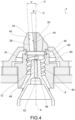
figures 3-4 show two sectional views of the air-jet spinning device offigure 1 , along the section plane H-H indicated infigure 1 ; -
figures 5-6 show two sectional views of the air-jet spinning device offigure 1 , along the section plane H-H indicated infigure 1 , according to a possible embodiment variant. - Elements or parts of elements in common to the embodiments described below are referred to with the same reference numerals.
- With reference to the aforementioned
figures, 4 indicates globally an air-jet type spinning device, comprising an at least partiallyhollow body 8 which delimits acylindrical spinning chamber 12. - The body comprises at least one
injection hole 16 configured to introduce a flow of compressed air into saidspinning chamber 12 and thereby obtain the formation of yarn through the fibre twisting. - For this purpose, the
spinning device 4 comprises afibre feeding device 20, facing saidspinning chamber 12 so as to be able to feed the fibres in thespinning chamber 12. - In turn, the
fibre feeding device 20 comprises afibre feeding channel 24 having a firststraight section 28 leading, at ashoulder 32, into a pre-chamber 36 facing and communicating with saidspinning chamber 12. - Preferably, the first
straight section 28 of thefibre feeding channel 24, with respect to a section plane passing through a median plane M-M of the firststraight section 28 and through a central axis C-C of thefibre feeding device 20, is inclined (i.e. not parallel) with respect to said central axis C-C. - Preferably, the first
straight section 28, with respect to a cross-section plane passing through a median plane M-M of said firststraight section 28 and a central axis C-C of thefibre feeding device 20, has a truncated-conical cross-section diverging towards thespinning chamber 12. - According to an embodiment, said first
straight section 28, with respect to a cross-section plane passing through a median plane M-M of the firststraight section 28 and a central axis C-C of thefibre feeding device 20, is delimited by anexternal wall 40 inclined with respect to the central axis C-C by an external angle α between 2° and 3.75°. - According to an embodiment, said first
straight section 28, with respect to a cross-section plane passing through a median plane M-M of the firststraight section 28 and a central axis C-C of thefibre feeding device 20, is delimited by aninner wall 44 inclined with respect to the central axis C-C by an inner angle β between 3.5° and 5.5° . - The particular geometrical conformation of the
fibre feeding channel 24 contributes to the improved formation of the yarn and to the constancy of the spinning conditions. - The
spinning device 4 further comprises aspinning spindle 48 at least partially inserted in thespinning chamber 12 and provided with aspinning channel 52 for the passage of yarn obtained from said fibres. - The spinning
channel 52 has a main axis which defines a spinning direction (X-X) and has afront inlet 56 for introducing the fibres into said spinningchannel 52. - Advantageously, the spinning chamber has extremely compact dimensions.
- A
diameter 60 of thespinning chamber 12, measured relative to a cross-section plane perpendicular to said main axis, is between 5.6 and 7.4 mm. - According to one embodiment, the
spinning spindle 48 has an overall frusto-conical shape with a circular and axially symmetrical section with respect to said spinning direction X-X; in particular, thespinning spindle 48 tapers towards thefront inlet 56. - Preferably, said spinning
spindle 48 has aninlet diameter 64, at saidfront inlet 56, comprised between 47% and 61% of thediameter 60 of thespinning chamber 12. - Preferably, said
inlet diameter 64 is between 3.2 and 3.9 mm. - As mentioned, the spinning
spindle 48 has a truncated cone shape, wherein anaverage diameter 68 of said spinning spindle, at an intermediate height of thespinning spindle 48, is equal to 1.1 - 1.3 times theinlet diameter 64 of the spinningspindle 48, at saidfront inlet 56. - Preferably, a
bottom diameter 72 of thespinning spindle 48, on the opposite side to itsfront inlet 56, is equal to 1.1 - 1.3 times saidaverage diameter 68. - The injection hole also has a specific position with respect to the
spinning chamber 12 and/or the spinningspindle 48. - Said at least one
injection hole 16 is arranged upstream of thefront inlet 56 of the spinningspindle 48, along said spinning direction. - Preferably, said at least one
injection hole 16 is arranged at adistance 76 from theshoulder 32 of between 2.4 and 3.5 mm. - The distance between the at least one
injection hole 16 and thefront inlet 56 of the spinningchannel 52, measured parallel to the spinning direction, is greater than or equal to 0.3 mm, and theinjection hole 16 is arranged upstream of thefront inlet 56. - In other words, the
injection hole 16 is located just upstream, i.e. above, with respect to thefront inlet 56 of the spinningchannel 52. - Also the
spinning chamber 12 has some peculiarity. - The
spinning chamber 12 is delimited at least partially by anouter side wall 80, opposite thespinning spindle 48, wherein on saidouter side wall 80 at least onethread 84 is made; moreover, said at least oneinjection hole 16 is oriented so as to direct the jet of compressed air towards the at least onethread 84 so as to be guided and oriented by the latter. - In other words, the
thread 84 acts as a guide for the movement of the air flow inside thespinning chamber 12. - Preferably, the at least one
thread 84 is a helical thread, coaxial with said spinningchannel 52 and parallel to the spinning direction (X-X). - The
spinning device 4 comprises at least twoinjection holes 16 which direct compressed air into two distinct emission points of a samehelical thread 84; said emission points are diametrically opposed to each other and send jets of compressed air in opposite directions to each other, so as to generate a synchronised motion of vorticity which triggers the twisting of the fibres in thespinning chamber 12. - According to a possible embodiment, said
thread 84 has a geometry with a curvilinear or semicircular section, preferably with a radius of between 0.25 mm and 2 mm. - Preferably, said
thread 84 is inclined according to a helix angle of between 5° and 15°. - Preferably, the pitch of said
thread 84 is between 1.5 mm and 4 mm. - The
outer side wall 80 can also comprise a plurality of threads which direct and guide as many flows of compressed air. - According to an embodiment, the
fibre feeding device 20 comprises aneedle 88, at least partially penetrated in saidspinning chamber 12 and axially opposite saidfront inlet 56, so as to create a guide for the fibres being spun. - As can be seen from the above description, the air-jet type spinning device according to the invention allows the drawbacks of the prior art to be overcome.
- In particular, the present invention can lead to a reduction in air consumption with respect to the solutions of the prior art, since the total air flow is dosed and optimized in all operating conditions of the device.
- In the solution of the present invention, the spinning chamber is wider: this increased space serves to open the fibres and to wind the flow of untwisted central fibres with greater tension and effectiveness. In particular, the increased dimensions of the spinning chamber are important in order to be able to pull the fibres from the outside, making the twisting on the bundle of central fibres more efficient.
- These dimensional/geometric expedients allow a net improvement in the quality of the resulting yarn as it is possible to allow more fibres to participate in the formation of the yarn twisting.
- Furthermore, as seen, the greater volume available allows managing the possible presence of balls or dust or dirt, as the dimensions allow the escape of said impurities without excessively disturbing the fluid motion field.
- It should also be noted that it is possible to use only two air injection holes and reduce the overall working pressure, due to the greater efficiency of the spinning chamber.
- This is a further advantage, since interference between the fibres and the air is avoided and therefore the spinning process becomes more controllable, so as to obtain a yarn with features that are as constant and repeatable as possible.
- The larger dimensions with respect to the prior art have the advantage of allowing the fibres to "open up" for a longer stretch, without interfering with the outer walls. This allows having longer stretches of wound fibres and therefore greater regularity and strength to the yarn.
- Furthermore, in yarns with large counts (thread count < Tex 20 (Ne30)) the high number of fibres being worked requires additional "space" since the external fibres involved will be higher in number than the average and fine counts and this requires more working space.
Claims (16)
- Air-jet type spinning device (4) comprising- a body (8) at least partially hollow, which delimits a cylindrical spinning chamber (12), the body comprising at least one injection hole (16) configured to inject a flow of compressed air into said spinning chamber (12),- a fibre feeding device (20), facing said spinning chamber (12) so as to feed the fibres into the spinning chamber (12),- the fibre feeding device (20) comprising a fibre feeding channel (24) having a first straight section (28) leading, at a shoulder (32), into a pre-chamber (36) facing and communicating with said spinning chamber (12),- a spinning spindle (48) at least partially inserted in the spinning chamber (12) and fitted with a spinning channel (52) for the transit of yarn obtained from said fibres, the spinning channel (52) having a main axis which defines a spinning direction (X-X), and having a front inlet (56) for the introduction of the yarn in said spinning channel (52),wherein the distance between the at least one injection hole (16) and the front inlet (56), measured parallel to the spinning direction (X-X), is greater than or equal to 0.3 mm, the injection hole (16) being arranged upstream of the front inlet (56),wherein the spinning chamber (12) is delimited at least partially by an outer side wall (80), opposite the spinning spindle (48), wherein on said outer side wall (80) at least one thread (84) is made, wherein said at least one injection hole (16) is oriented so as to direct the jet of compressed air towards the at least one thread (84) so as to be guided and oriented by the latter, wherein the spinning device (4) comprises at least two injection holes (16) that direct compressed air at two separate emission points of the same helical thread (84),characterised in that a diameter (60) of the spinning chamber (12), measured relative to a cross-section plane perpendicular to said main axis, is between 5.6 and 7.4 mm and in that said emission points are diametrically opposite to a each other and send jets of compressed air in opposite directions to each other.
- Air-jet type spinning device (4) according to claim 1, wherein the spinning spindle (48) has, overall, a truncated cone shape with a circular and axial symmetric cross-section with respect to said spinning direction (X-X), the spinning spindle (48) tapering towards the front inlet (56).
- Air-jet type spinning device (4) according to claim 1 or 2, wherein said spinning spindle (48) has an inlet diameter (64), at said front inlet (56), between 47% and 61% of the diameter (60) of the spinning chamber (12).
- Air-jet type spinning device (4) according to claim 3 wherein said inlet diameter (64) is between 3.2 mm and 3.9 mm.
- Air-jet type spinning device (4) according to any one of the preceding claims, wherein the spinning spindle (48) has a truncated cone shape, wherein an average diameter (68) of said spinning spindle, at an intermediate height of the spinning spindle (48), is equal to 1.1 - 1.3 times an inlet diameter (64) of the spinning spindle (48), at said front inlet (56).
- Air-jet type spinning device (4) according to claim 5, wherein a bottom diameter (72) of the spinning spindle (48), opposite the front inlet (56), is equal to 1.1 - 1.3 times said average diameter (68).
- Air-jet type spinning device (4) according to any one of the preceding claims, wherein the first straight section (28) of the fibre feeding channel (24), with respect to a cross-section plane passing through a median plane (M-M) of the first straight section (28) and a central axis (C-C) of the feeding device (4), is inclined with respect to said central axis (C-C).
- Air-jet type spinning device (4) according to any one of the preceding claims, wherein the first straight section (28), with respect to a cross-section plane passing through a median plane (M-M) of said first straight section (28) and a central axis (C-C) of the fibre feeding device (20), has a truncated-conical cross-section diverging towards the spinning chamber (12).
- Air-jet type spinning device (4) according to any one of the preceding claims, wherein said first straight section (28), with respect to a cross-section plane passing through a median plane (M-M) of the first straight section (28) and a central axis (C-C) of the fibre feeding device (20), is delimited by an external wall (40) inclined with respect to the central axis (C-C) by an external angle (α) between 2° and 3.75°.
- Air-jet type spinning device (4) according to any one of the preceding claims, wherein said first straight section (28), with respect to a cross-section plane passing through a median plane (M-M) of the first straight section (28) and a central axis (C-C) of the fibre feeding device (20), is delimited by an inner wall (44) inclined with respect to the central axis (C-C) by an inner angle (β) between 3.5° and 5.5°.
- Air-jet type spinning device (4) according to any of the preceding claims, wherein said at least one injection hole (16) is placed at a distance (76) from the shoulder (32) between 2.4 and 3.5 mm.
- Air-jet type spinning device (4) according to any one of the preceding claims, wherein said at least one thread (84) is a helical thread, coaxial with said spinning channel (52) and parallel to the spinning direction (X-X).
- Air-jet type spinning device (4) according to any of the claims from 1 to 12, 13, wherein said thread (84) has a curved or semi-circular geometry cross-section, preferably with a radius between 0.25 mm and 2 mm.
- Air-jet type spinning device (4) according to any of the claims from 1 to 13 wherein said thread (84) is inclined at a helix angle of between 5° and 15°.
- Air-jet type spinning device (4) according to any of the claims from 1 to 14 wherein the pitch of said thread (84) is between 1.5 mm and 4 mm.
- Air-jet type spinning device (4) according to any of the preceding claims, wherein the fibre feeding device (20) comprises a needle (88), at least partially penetrated in said spinning chamber (12) and axially counterposed to said front inlet (56), so as to create a guide for the fibres being spun.
Applications Claiming Priority (1)
| Application Number | Priority Date | Filing Date | Title |
|---|---|---|---|
| IT102018000009728A IT201800009728A1 (en) | 2018-10-24 | 2018-10-24 | AIR-JET TYPE SPINNING DEVICE |
Publications (2)
| Publication Number | Publication Date |
|---|---|
| EP3643818A1 EP3643818A1 (en) | 2020-04-29 |
| EP3643818B1 true EP3643818B1 (en) | 2024-09-04 |
Family
ID=65324451
Family Applications (1)
| Application Number | Title | Priority Date | Filing Date |
|---|---|---|---|
| EP19204430.3A Active EP3643818B1 (en) | 2018-10-24 | 2019-10-21 | Air-jet type spinning device |
Country Status (4)
| Country | Link |
|---|---|
| US (1) | US11155939B2 (en) |
| EP (1) | EP3643818B1 (en) |
| CN (2) | CN211570881U (en) |
| IT (1) | IT201800009728A1 (en) |
Families Citing this family (3)
| Publication number | Priority date | Publication date | Assignee | Title |
|---|---|---|---|---|
| IT201800009728A1 (en) * | 2018-10-24 | 2020-04-24 | Savio Macch Tessili Spa | AIR-JET TYPE SPINNING DEVICE |
| DE102020133359A1 (en) * | 2020-12-14 | 2022-06-15 | Saurer Spinning Solutions Gmbh & Co. Kg | Multifunction nozzle for a spinning machine |
| DE102022114064A1 (en) | 2022-06-03 | 2023-12-14 | Saurer Spinning Solutions Gmbh & Co. Kg | Thread take-off nozzle and open-end spinning device with a thread take-off nozzle |
Family Cites Families (12)
| Publication number | Priority date | Publication date | Assignee | Title |
|---|---|---|---|---|
| US5146740A (en) * | 1990-02-20 | 1992-09-15 | Murata Kikai Kabushiki Kaisha | Spinning apparatus |
| US5263310A (en) * | 1990-02-20 | 1993-11-23 | Murata Kikai Kabushiki Kaisha | Spinning apparatus |
| CN102304788B (en) * | 2007-06-04 | 2014-07-30 | 村田机械株式会社 | Spinning device |
| CN101294319B (en) * | 2008-05-26 | 2010-06-02 | 东华大学 | Air-jet vortex spinning device with low noil |
| JP5526915B2 (en) * | 2010-03-25 | 2014-06-18 | 村田機械株式会社 | Pneumatic spinning device and spinning machine |
| CH704780A1 (en) * | 2011-04-13 | 2012-10-15 | Rieter Ag Maschf | Roving machine for manufacturing a roving. |
| CH705221A1 (en) * | 2011-07-01 | 2013-01-15 | Rieter Ag Maschf | Roving for producing a roving and method for piecing a fiber association. |
| CN102618973B (en) * | 2012-03-01 | 2013-03-27 | 江阴市华方新技术科研有限公司 | Spinning nozzle structure |
| DE102012108613A1 (en) * | 2012-09-14 | 2014-03-20 | Maschinenfabrik Rieter Ag | Spinning station of a roving machine |
| ITUA20163011A1 (en) * | 2016-04-29 | 2017-10-29 | Savio Macch Tessili Spa | AIR-JET TYPE SPINNING DEVICE |
| IT201600070676A1 (en) * | 2016-07-07 | 2018-01-07 | Savio Macch Tessili Spa | Air-jet spinning device |
| IT201800009728A1 (en) * | 2018-10-24 | 2020-04-24 | Savio Macch Tessili Spa | AIR-JET TYPE SPINNING DEVICE |
-
2018
- 2018-10-24 IT IT102018000009728A patent/IT201800009728A1/en unknown
-
2019
- 2019-10-21 EP EP19204430.3A patent/EP3643818B1/en active Active
- 2019-10-24 US US16/662,259 patent/US11155939B2/en active Active
- 2019-10-24 CN CN201921804734.XU patent/CN211570881U/en active Active
- 2019-10-24 CN CN201911017780.XA patent/CN111088566B/en active Active
Also Published As
| Publication number | Publication date |
|---|---|
| IT201800009728A1 (en) | 2020-04-24 |
| US20200131673A1 (en) | 2020-04-30 |
| US11155939B2 (en) | 2021-10-26 |
| CN111088566B (en) | 2024-01-19 |
| CN211570881U (en) | 2020-09-25 |
| EP3643818A1 (en) | 2020-04-29 |
| CN111088566A (en) | 2020-05-01 |
Similar Documents
| Publication | Publication Date | Title |
|---|---|---|
| US10851478B2 (en) | Air-jet type spinning device | |
| US11155939B2 (en) | Air-jet type spinning device | |
| EP3243941B1 (en) | Air-jet type spinning device | |
| CN101294319B (en) | Air-jet vortex spinning device with low noil | |
| CN101268222A (en) | Air nozzle assembly for an air jet spinning device | |
| US9670599B2 (en) | Spinning station of an air jet spinning machine | |
| US9677197B2 (en) | Spinning station of a spinning preparation machine | |
| CN103603094B (en) | A kind of air injection air vortex spinning apparatus of side entrance | |
| GB2115019A (en) | False twisting air nozzle | |
| JP5698232B2 (en) | Pneumatic spinning equipment | |
| CN102618974B (en) | Device for twisting single yarn into compound yarn in spinning process | |
| EP3266910B1 (en) | Air-jet type spinning device | |
| CN104126036A (en) | Yarn forming element for a spinning station of an air spinning machine with helical guide elements and method for producing yarn | |
| CN102926054B (en) | Air injection vortex spinning device with pumping component | |
| CN105765119A (en) | Fiber guiding element for a spinneret of an air-jet spinning machine, and spinning station equipped with such a fiber guiding element | |
| CN111411426B (en) | Fiber guiding element for a spinneret and spinneret provided with said fiber guiding element | |
| CN110656407B (en) | Vortex spinning nozzle device | |
| CN211256185U (en) | Vortex spinning nozzle device | |
| IL25990A (en) | Pneumatic false twister | |
| CN109154110A (en) | Yarn for fly frame forms element and is equipped with the fly frame that yarn forms element | |
| CN100467685C (en) | Spinning device, spinning method, and hollow guide shaft part for spinning | |
| CN213447439U (en) | Vortex spinning vortex tube | |
| CN211284662U (en) | Novel spinning tube for vortex spinning machine | |
| CN121496618A (en) | A jet vortex spinning tube capable of spinning dense yarns | |
| CN107881606A (en) | A kind of modified form device for turbo-spinning |
Legal Events
| Date | Code | Title | Description |
|---|---|---|---|
| PUAI | Public reference made under article 153(3) epc to a published international application that has entered the european phase |
Free format text: ORIGINAL CODE: 0009012 |
|
| STAA | Information on the status of an ep patent application or granted ep patent |
Free format text: STATUS: THE APPLICATION HAS BEEN PUBLISHED |
|
| AK | Designated contracting states |
Kind code of ref document: A1 Designated state(s): AL AT BE BG CH CY CZ DE DK EE ES FI FR GB GR HR HU IE IS IT LI LT LU LV MC MK MT NL NO PL PT RO RS SE SI SK SM TR |
|
| AX | Request for extension of the european patent |
Extension state: BA ME |
|
| STAA | Information on the status of an ep patent application or granted ep patent |
Free format text: STATUS: REQUEST FOR EXAMINATION WAS MADE |
|
| 17P | Request for examination filed |
Effective date: 20201019 |
|
| RBV | Designated contracting states (corrected) |
Designated state(s): AL AT BE BG CH CY CZ DE DK EE ES FI FR GB GR HR HU IE IS IT LI LT LU LV MC MK MT NL NO PL PT RO RS SE SI SK SM TR |
|
| STAA | Information on the status of an ep patent application or granted ep patent |
Free format text: STATUS: EXAMINATION IS IN PROGRESS |
|
| 17Q | First examination report despatched |
Effective date: 20220513 |
|
| P01 | Opt-out of the competence of the unified patent court (upc) registered |
Effective date: 20230526 |
|
| GRAP | Despatch of communication of intention to grant a patent |
Free format text: ORIGINAL CODE: EPIDOSNIGR1 |
|
| STAA | Information on the status of an ep patent application or granted ep patent |
Free format text: STATUS: GRANT OF PATENT IS INTENDED |
|
| INTG | Intention to grant announced |
Effective date: 20240521 |
|
| GRAS | Grant fee paid |
Free format text: ORIGINAL CODE: EPIDOSNIGR3 |
|
| GRAA | (expected) grant |
Free format text: ORIGINAL CODE: 0009210 |
|
| STAA | Information on the status of an ep patent application or granted ep patent |
Free format text: STATUS: THE PATENT HAS BEEN GRANTED |
|
| AK | Designated contracting states |
Kind code of ref document: B1 Designated state(s): AL AT BE BG CH CY CZ DE DK EE ES FI FR GB GR HR HU IE IS IT LI LT LU LV MC MK MT NL NO PL PT RO RS SE SI SK SM TR |
|
| REG | Reference to a national code |
Ref country code: GB Ref legal event code: FG4D |
|
| REG | Reference to a national code |
Ref country code: CH Ref legal event code: EP |
|
| REG | Reference to a national code |
Ref country code: IE Ref legal event code: FG4D |
|
| REG | Reference to a national code |
Ref country code: DE Ref legal event code: R096 Ref document number: 602019058215 Country of ref document: DE |
|
| REG | Reference to a national code |
Ref country code: LT Ref legal event code: MG9D |
|
| REG | Reference to a national code |
Ref country code: NL Ref legal event code: MP Effective date: 20240904 |
|
| PG25 | Lapsed in a contracting state [announced via postgrant information from national office to epo] |
Ref country code: NO Free format text: LAPSE BECAUSE OF FAILURE TO SUBMIT A TRANSLATION OF THE DESCRIPTION OR TO PAY THE FEE WITHIN THE PRESCRIBED TIME-LIMIT Effective date: 20241204 |
|
| PG25 | Lapsed in a contracting state [announced via postgrant information from national office to epo] |
Ref country code: PL Free format text: LAPSE BECAUSE OF FAILURE TO SUBMIT A TRANSLATION OF THE DESCRIPTION OR TO PAY THE FEE WITHIN THE PRESCRIBED TIME-LIMIT Effective date: 20240904 Ref country code: GR Free format text: LAPSE BECAUSE OF FAILURE TO SUBMIT A TRANSLATION OF THE DESCRIPTION OR TO PAY THE FEE WITHIN THE PRESCRIBED TIME-LIMIT Effective date: 20241205 Ref country code: FI Free format text: LAPSE BECAUSE OF FAILURE TO SUBMIT A TRANSLATION OF THE DESCRIPTION OR TO PAY THE FEE WITHIN THE PRESCRIBED TIME-LIMIT Effective date: 20240904 |
|
| PG25 | Lapsed in a contracting state [announced via postgrant information from national office to epo] |
Ref country code: BG Free format text: LAPSE BECAUSE OF FAILURE TO SUBMIT A TRANSLATION OF THE DESCRIPTION OR TO PAY THE FEE WITHIN THE PRESCRIBED TIME-LIMIT Effective date: 20240904 |
|
| PG25 | Lapsed in a contracting state [announced via postgrant information from national office to epo] |
Ref country code: LV Free format text: LAPSE BECAUSE OF FAILURE TO SUBMIT A TRANSLATION OF THE DESCRIPTION OR TO PAY THE FEE WITHIN THE PRESCRIBED TIME-LIMIT Effective date: 20240904 |
|
| PG25 | Lapsed in a contracting state [announced via postgrant information from national office to epo] |
Ref country code: HR Free format text: LAPSE BECAUSE OF FAILURE TO SUBMIT A TRANSLATION OF THE DESCRIPTION OR TO PAY THE FEE WITHIN THE PRESCRIBED TIME-LIMIT Effective date: 20240904 |
|
| PG25 | Lapsed in a contracting state [announced via postgrant information from national office to epo] |
Ref country code: ES Free format text: LAPSE BECAUSE OF FAILURE TO SUBMIT A TRANSLATION OF THE DESCRIPTION OR TO PAY THE FEE WITHIN THE PRESCRIBED TIME-LIMIT Effective date: 20240904 Ref country code: RS Free format text: LAPSE BECAUSE OF FAILURE TO SUBMIT A TRANSLATION OF THE DESCRIPTION OR TO PAY THE FEE WITHIN THE PRESCRIBED TIME-LIMIT Effective date: 20241204 |
|
| PG25 | Lapsed in a contracting state [announced via postgrant information from national office to epo] |
Ref country code: RS Free format text: LAPSE BECAUSE OF FAILURE TO SUBMIT A TRANSLATION OF THE DESCRIPTION OR TO PAY THE FEE WITHIN THE PRESCRIBED TIME-LIMIT Effective date: 20241204 Ref country code: PL Free format text: LAPSE BECAUSE OF FAILURE TO SUBMIT A TRANSLATION OF THE DESCRIPTION OR TO PAY THE FEE WITHIN THE PRESCRIBED TIME-LIMIT Effective date: 20240904 Ref country code: NO Free format text: LAPSE BECAUSE OF FAILURE TO SUBMIT A TRANSLATION OF THE DESCRIPTION OR TO PAY THE FEE WITHIN THE PRESCRIBED TIME-LIMIT Effective date: 20241204 Ref country code: LV Free format text: LAPSE BECAUSE OF FAILURE TO SUBMIT A TRANSLATION OF THE DESCRIPTION OR TO PAY THE FEE WITHIN THE PRESCRIBED TIME-LIMIT Effective date: 20240904 Ref country code: HR Free format text: LAPSE BECAUSE OF FAILURE TO SUBMIT A TRANSLATION OF THE DESCRIPTION OR TO PAY THE FEE WITHIN THE PRESCRIBED TIME-LIMIT Effective date: 20240904 Ref country code: GR Free format text: LAPSE BECAUSE OF FAILURE TO SUBMIT A TRANSLATION OF THE DESCRIPTION OR TO PAY THE FEE WITHIN THE PRESCRIBED TIME-LIMIT Effective date: 20241205 Ref country code: FI Free format text: LAPSE BECAUSE OF FAILURE TO SUBMIT A TRANSLATION OF THE DESCRIPTION OR TO PAY THE FEE WITHIN THE PRESCRIBED TIME-LIMIT Effective date: 20240904 Ref country code: ES Free format text: LAPSE BECAUSE OF FAILURE TO SUBMIT A TRANSLATION OF THE DESCRIPTION OR TO PAY THE FEE WITHIN THE PRESCRIBED TIME-LIMIT Effective date: 20240904 Ref country code: BG Free format text: LAPSE BECAUSE OF FAILURE TO SUBMIT A TRANSLATION OF THE DESCRIPTION OR TO PAY THE FEE WITHIN THE PRESCRIBED TIME-LIMIT Effective date: 20240904 |
|
| REG | Reference to a national code |
Ref country code: AT Ref legal event code: MK05 Ref document number: 1720477 Country of ref document: AT Kind code of ref document: T Effective date: 20240904 |
|
| PG25 | Lapsed in a contracting state [announced via postgrant information from national office to epo] |
Ref country code: NL Free format text: LAPSE BECAUSE OF FAILURE TO SUBMIT A TRANSLATION OF THE DESCRIPTION OR TO PAY THE FEE WITHIN THE PRESCRIBED TIME-LIMIT Effective date: 20240904 |
|
| PG25 | Lapsed in a contracting state [announced via postgrant information from national office to epo] |
Ref country code: IS Free format text: LAPSE BECAUSE OF FAILURE TO SUBMIT A TRANSLATION OF THE DESCRIPTION OR TO PAY THE FEE WITHIN THE PRESCRIBED TIME-LIMIT Effective date: 20250104 Ref country code: PT Free format text: LAPSE BECAUSE OF FAILURE TO SUBMIT A TRANSLATION OF THE DESCRIPTION OR TO PAY THE FEE WITHIN THE PRESCRIBED TIME-LIMIT Effective date: 20250106 |
|
| PG25 | Lapsed in a contracting state [announced via postgrant information from national office to epo] |
Ref country code: SM Free format text: LAPSE BECAUSE OF FAILURE TO SUBMIT A TRANSLATION OF THE DESCRIPTION OR TO PAY THE FEE WITHIN THE PRESCRIBED TIME-LIMIT Effective date: 20240904 Ref country code: RO Free format text: LAPSE BECAUSE OF FAILURE TO SUBMIT A TRANSLATION OF THE DESCRIPTION OR TO PAY THE FEE WITHIN THE PRESCRIBED TIME-LIMIT Effective date: 20240904 |
|
| PG25 | Lapsed in a contracting state [announced via postgrant information from national office to epo] |
Ref country code: EE Free format text: LAPSE BECAUSE OF FAILURE TO SUBMIT A TRANSLATION OF THE DESCRIPTION OR TO PAY THE FEE WITHIN THE PRESCRIBED TIME-LIMIT Effective date: 20240904 Ref country code: AT Free format text: LAPSE BECAUSE OF FAILURE TO SUBMIT A TRANSLATION OF THE DESCRIPTION OR TO PAY THE FEE WITHIN THE PRESCRIBED TIME-LIMIT Effective date: 20240904 |
|
| PG25 | Lapsed in a contracting state [announced via postgrant information from national office to epo] |
Ref country code: CZ Free format text: LAPSE BECAUSE OF FAILURE TO SUBMIT A TRANSLATION OF THE DESCRIPTION OR TO PAY THE FEE WITHIN THE PRESCRIBED TIME-LIMIT Effective date: 20240904 |
|
| PG25 | Lapsed in a contracting state [announced via postgrant information from national office to epo] |
Ref country code: SK Free format text: LAPSE BECAUSE OF FAILURE TO SUBMIT A TRANSLATION OF THE DESCRIPTION OR TO PAY THE FEE WITHIN THE PRESCRIBED TIME-LIMIT Effective date: 20240904 |
|
| REG | Reference to a national code |
Ref country code: CH Ref legal event code: PL |
|
| REG | Reference to a national code |
Ref country code: DE Ref legal event code: R097 Ref document number: 602019058215 Country of ref document: DE |
|
| PG25 | Lapsed in a contracting state [announced via postgrant information from national office to epo] |
Ref country code: MC Free format text: LAPSE BECAUSE OF FAILURE TO SUBMIT A TRANSLATION OF THE DESCRIPTION OR TO PAY THE FEE WITHIN THE PRESCRIBED TIME-LIMIT Effective date: 20240904 |
|
| PG25 | Lapsed in a contracting state [announced via postgrant information from national office to epo] |
Ref country code: DK Free format text: LAPSE BECAUSE OF FAILURE TO SUBMIT A TRANSLATION OF THE DESCRIPTION OR TO PAY THE FEE WITHIN THE PRESCRIBED TIME-LIMIT Effective date: 20240904 |
|
| PLBE | No opposition filed within time limit |
Free format text: ORIGINAL CODE: 0009261 |
|
| STAA | Information on the status of an ep patent application or granted ep patent |
Free format text: STATUS: NO OPPOSITION FILED WITHIN TIME LIMIT |
|
| PG25 | Lapsed in a contracting state [announced via postgrant information from national office to epo] |
Ref country code: BE Free format text: LAPSE BECAUSE OF NON-PAYMENT OF DUE FEES Effective date: 20241031 Ref country code: LU Free format text: LAPSE BECAUSE OF NON-PAYMENT OF DUE FEES Effective date: 20241021 |
|
| PG25 | Lapsed in a contracting state [announced via postgrant information from national office to epo] |
Ref country code: CH Free format text: LAPSE BECAUSE OF NON-PAYMENT OF DUE FEES Effective date: 20241031 |
|
| REG | Reference to a national code |
Ref country code: BE Ref legal event code: MM Effective date: 20241031 |
|
| 26N | No opposition filed |
Effective date: 20250605 |
|
| GBPC | Gb: european patent ceased through non-payment of renewal fee |
Effective date: 20241204 |
|
| PG25 | Lapsed in a contracting state [announced via postgrant information from national office to epo] |
Ref country code: SE Free format text: LAPSE BECAUSE OF FAILURE TO SUBMIT A TRANSLATION OF THE DESCRIPTION OR TO PAY THE FEE WITHIN THE PRESCRIBED TIME-LIMIT Effective date: 20240904 |
|
| PGFP | Annual fee paid to national office [announced via postgrant information from national office to epo] |
Ref country code: IT Payment date: 20250908 Year of fee payment: 7 |
|
| PG25 | Lapsed in a contracting state [announced via postgrant information from national office to epo] |
Ref country code: GB Free format text: LAPSE BECAUSE OF NON-PAYMENT OF DUE FEES Effective date: 20241204 |
|
| PG25 | Lapsed in a contracting state [announced via postgrant information from national office to epo] |
Ref country code: FR Free format text: LAPSE BECAUSE OF NON-PAYMENT OF DUE FEES Effective date: 20241104 |
|
| PG25 | Lapsed in a contracting state [announced via postgrant information from national office to epo] |
Ref country code: IE Free format text: LAPSE BECAUSE OF NON-PAYMENT OF DUE FEES Effective date: 20241021 |
|
| PGFP | Annual fee paid to national office [announced via postgrant information from national office to epo] |
Ref country code: DE Payment date: 20251027 Year of fee payment: 7 |
|
| PGFP | Annual fee paid to national office [announced via postgrant information from national office to epo] |
Ref country code: TR Payment date: 20251006 Year of fee payment: 7 |
|
| PG25 | Lapsed in a contracting state [announced via postgrant information from national office to epo] |
Ref country code: CY Free format text: LAPSE BECAUSE OF FAILURE TO SUBMIT A TRANSLATION OF THE DESCRIPTION OR TO PAY THE FEE WITHIN THE PRESCRIBED TIME-LIMIT; INVALID AB INITIO Effective date: 20191021 |
|
| PG25 | Lapsed in a contracting state [announced via postgrant information from national office to epo] |
Ref country code: HU Free format text: LAPSE BECAUSE OF FAILURE TO SUBMIT A TRANSLATION OF THE DESCRIPTION OR TO PAY THE FEE WITHIN THE PRESCRIBED TIME-LIMIT; INVALID AB INITIO Effective date: 20191021 |
|
| PG25 | Lapsed in a contracting state [announced via postgrant information from national office to epo] |
Ref country code: SI Free format text: LAPSE BECAUSE OF FAILURE TO SUBMIT A TRANSLATION OF THE DESCRIPTION OR TO PAY THE FEE WITHIN THE PRESCRIBED TIME-LIMIT Effective date: 20240904 |
|
| PG25 | Lapsed in a contracting state [announced via postgrant information from national office to epo] |
Ref country code: LT Free format text: LAPSE BECAUSE OF FAILURE TO SUBMIT A TRANSLATION OF THE DESCRIPTION OR TO PAY THE FEE WITHIN THE PRESCRIBED TIME-LIMIT Effective date: 20240904 |