EP3643530A1 - Bead core, production method therefor, and pneumatic tire - Google Patents
Bead core, production method therefor, and pneumatic tire Download PDFInfo
- Publication number
- EP3643530A1 EP3643530A1 EP18820415.0A EP18820415A EP3643530A1 EP 3643530 A1 EP3643530 A1 EP 3643530A1 EP 18820415 A EP18820415 A EP 18820415A EP 3643530 A1 EP3643530 A1 EP 3643530A1
- Authority
- EP
- European Patent Office
- Prior art keywords
- annular body
- bead core
- strip member
- bead
- cross
- Prior art date
- Legal status (The legal status is an assumption and is not a legal conclusion. Google has not performed a legal analysis and makes no representation as to the accuracy of the status listed.)
- Granted
Links
Images


Classifications
-
- B—PERFORMING OPERATIONS; TRANSPORTING
- B29—WORKING OF PLASTICS; WORKING OF SUBSTANCES IN A PLASTIC STATE IN GENERAL
- B29D—PRODUCING PARTICULAR ARTICLES FROM PLASTICS OR FROM SUBSTANCES IN A PLASTIC STATE
- B29D30/00—Producing pneumatic or solid tyres or parts thereof
- B29D30/06—Pneumatic tyres or parts thereof (e.g. produced by casting, moulding, compression moulding, injection moulding, centrifugal casting)
- B29D30/48—Bead-rings or bead-cores; Treatment thereof prior to building the tyre
- B29D30/50—Covering, e.g. by winding, the separate bead-rings or bead-cores with textile material, e.g. with flipper strips
-
- B—PERFORMING OPERATIONS; TRANSPORTING
- B60—VEHICLES IN GENERAL
- B60C—VEHICLE TYRES; TYRE INFLATION; TYRE CHANGING; CONNECTING VALVES TO INFLATABLE ELASTIC BODIES IN GENERAL; DEVICES OR ARRANGEMENTS RELATED TO TYRES
- B60C15/00—Tyre beads, e.g. ply turn-up or overlap
- B60C15/04—Bead cores
-
- B—PERFORMING OPERATIONS; TRANSPORTING
- B29—WORKING OF PLASTICS; WORKING OF SUBSTANCES IN A PLASTIC STATE IN GENERAL
- B29D—PRODUCING PARTICULAR ARTICLES FROM PLASTICS OR FROM SUBSTANCES IN A PLASTIC STATE
- B29D30/00—Producing pneumatic or solid tyres or parts thereof
- B29D30/06—Pneumatic tyres or parts thereof (e.g. produced by casting, moulding, compression moulding, injection moulding, centrifugal casting)
- B29D30/48—Bead-rings or bead-cores; Treatment thereof prior to building the tyre
-
- B—PERFORMING OPERATIONS; TRANSPORTING
- B29—WORKING OF PLASTICS; WORKING OF SUBSTANCES IN A PLASTIC STATE IN GENERAL
- B29D—PRODUCING PARTICULAR ARTICLES FROM PLASTICS OR FROM SUBSTANCES IN A PLASTIC STATE
- B29D30/00—Producing pneumatic or solid tyres or parts thereof
- B29D30/06—Pneumatic tyres or parts thereof (e.g. produced by casting, moulding, compression moulding, injection moulding, centrifugal casting)
- B29D30/48—Bead-rings or bead-cores; Treatment thereof prior to building the tyre
- B29D2030/483—Treating the bead cores to increase rubber adhesion
-
- B—PERFORMING OPERATIONS; TRANSPORTING
- B29—WORKING OF PLASTICS; WORKING OF SUBSTANCES IN A PLASTIC STATE IN GENERAL
- B29D—PRODUCING PARTICULAR ARTICLES FROM PLASTICS OR FROM SUBSTANCES IN A PLASTIC STATE
- B29D30/00—Producing pneumatic or solid tyres or parts thereof
- B29D30/06—Pneumatic tyres or parts thereof (e.g. produced by casting, moulding, compression moulding, injection moulding, centrifugal casting)
- B29D30/48—Bead-rings or bead-cores; Treatment thereof prior to building the tyre
- B29D2030/485—Bead-rings or bead-cores; Treatment thereof prior to building the tyre the bead cores being made using a band containing a plurality of wires embedded in rubber
-
- B—PERFORMING OPERATIONS; TRANSPORTING
- B60—VEHICLES IN GENERAL
- B60C—VEHICLE TYRES; TYRE INFLATION; TYRE CHANGING; CONNECTING VALVES TO INFLATABLE ELASTIC BODIES IN GENERAL; DEVICES OR ARRANGEMENTS RELATED TO TYRES
- B60C15/00—Tyre beads, e.g. ply turn-up or overlap
- B60C15/04—Bead cores
- B60C2015/042—Bead cores characterised by the material of the core, e.g. alloy
Definitions
- the present disclosure relates to a bead core, a manufacturing method of the same, and a pneumatic tire.
- a bead core comprising a bead wire coated with a coating resin
- a coating resin such as a thermoplastic resin
- PTL 1 Japanese Patent Laid-Open No. 2011-207157
- a bead core having a high durability a pneumatic tire including the bead core in a bead portion, and a manufacturing method of the bead core by which such a bead core is obtainable.
- a gist configuration of the present disclosure is as follows.
- a bead core of the present disclosure is a bead core comprising an annular body in which a strip member comprising one or more bead wires coated with a coating resin is wound and stacked, wherein in an axial cross section of the annular body, an interface between stacks adjacent to each other is non-linear.
- a manufacturing method of a bead core of the present disclosure comprises an annular body forming step of winding and stacking a strip member comprising one or more bead wires coated with a coating resin to form an annular body, wherein the strip member has an upper side and a lower side in a cross section orthogonal to an extending direction of the strip member, and the upper side and the lower side are non-linear in the cross section.
- a pneumatic tire of the present disclosure comprises a bead portion, and comprises the above bead core in the bead portion.
- a bead core having a high durability a pneumatic tire including a bead core in a bead portion, and a manufacturing method of the bead core by which such a bead core is obtainable.
- FIG. 1 is an axial cross-sectional view of an annular body that forms a bead core according to an embodiment of the present disclosure.
- this bead core 1 is configured as an annular body in which a strip member 4 comprising one or more (in an illustrated example, two) bead wires 2 coated with a coating resin 3 is wound and stacked (three stacks in this cross section).
- the number of the bead wires 2 to be arranged in an axial direction of the annular body is two in one stack of strip member 4, but the present disclosure is not especially limited to this case.
- the number of the bead wires 2 may be one or more.
- the annular body has a configuration in which three stacks are stacked in this cross section, but two or more stacks may be stacked.
- the bead wire 2 an arbitrary known material can be used, and, for example, a steel cord can be used.
- the steel cord can comprise, for example, a steel monofilament or stranded wire.
- organic fibers, carbon fibers or the like may be used.
- thermoplastic elastomer for example, a thermoplastic elastomer or a thermoplastic resin can be used, or a resin that crosslinks by heat or an electron beam or a resin that cures by thermal dislocation can be used.
- thermoplastic elastomer examples include polyolefin thermoplastic elastomer (TPO), polystyrene thermoplastic elastomer (TPS), polyamide thermoplastic elastomer (TPA), polyurethane thermoplastic elastomer (TPU), polyester thermoplastic elastomer (TPC), and dynamic crosslinking thermoplastic elastomer (TPV).
- thermoplastic resin include polyurethane resin, polyolefin resin, vinyl chloride resin, and polyamide resin.
- thermoplastic resin a resin can be used in which, for example, a deflection temperature under load (under a load of 0.45 MPa) prescribed in ISO75-2 or ASTM D648 is 78°C or more, a tensile yield strength prescribed in JIS K7113 is 10 MPa or more, a tensile rupture elongation (JIS K7113) similarly prescribed in JIS K7113 is 50% or more, and Vicat softening temperature (A-method) prescribed in JIS K7206 is 130°C or more. It is preferable that the coating resin 3 that coats the bead wire 2 has a tensile elastic modulus (prescribed in JIS K7113: 1995) of 50 MPa or more.
- the tensile elastic modulus of the coating resin 3 that coats the bead wire 2 is 1000 MPa or less.
- the coating resin 3 mentioned herein does not contain a rubber (an organic polymer material that exhibits a rubber elasticity at normal temperature).
- mutual stacks have a state where the strip member 4 is wound while melting the coating resin 3 by hot plate welding or the like, and the molten coating resin 3 is solidified and joined.
- the stacks may be bonded and joined to each other with an adhesive or the like.
- FIG. 2 is a schematic side view of the bead core according to the embodiment of the present disclosure.
- FIG. 2 only illustrates the bead wire 2 for simplicity ( FIG. 2 illustrates a center line of the bead wire 2), and omits depiction of the coating resin 3.
- the bead wire 2 is spirally wound from a winding start end E1 about an axis O of the annular body in this cross-sectional view.
- F1, F2 and F3 indicate orbital positions, and in this example, a winding end edge E2 extends beyond at least a point F3. Therefore, when seen in an arbitrary radial position, three stacks or more of the bead wires 2 are stacked in this example.
- the length can be from 1/200 to 199/200 of an orbital distance from a point F2 to the point F3.
- an area where the coating resins come in contact with each other can increase between the bead wires 2 adjacent in a radial direction (a stack direction). Consequently, for example, adhesiveness or a welding force can be increased, and a tensile burden can be decreased.
- the bead core can have a reduced weight.
- the overlap length is preferably from 1/100 to 2/3 of the orbital distance from the point F2 to the point F3, and more preferably from 1/50 to 1/3 of the orbital distance from the point F2 to the point F3.
- the strip member 4 comprising one or more bead wires 2 coated with the coating resin 3 is wound and stacked to form the annular body (an annular body forming step).
- the strip member 4 is formed by coating an outer peripheral side of the bead wire 2 with the molten coating resin 3, and cooling and solidifying the resin.
- the annular body that forms the bead core 1 can be formed by winding and stacking the strip member 4, and the stacks can be joined to each other, for example, by winding the strip member 4 while melting the coating resin 3 by the hot plate welding or the like, and solidifying the molten coating resin 3.
- the stacks can be joined by bonding the stacks to each other with the adhesive or the like.
- a non-linear interface 5 in an axial cross section of the annular body, has an apex 5a in a central portion (a center and a peripheral portion around the center, the center in the illustrated example) of the annular body in the axial direction, and is inclined linearly in this example from the apex 5a toward both ends of the annular body in the axial direction and to one side of the annular body in a radial direction (inside in the radial direction in this example).
- the strip member 4 has an upper side and a lower side in this cross section, and the upper side and the lower side are non-linear in the cross section.
- Each of the upper side and the lower side has an apex in a central portion (a center and a peripheral portion around the center, the center in the illustrated example) of the strip member 4 in a width direction, and is inclined linearly in this example from the apex toward both ends of the strip member 4 in the width direction and to one side of the strip member 4 in a thickness direction (illustrated downside in the thickness direction in this example).
- the strip member 4 has a cross-sectional shape formed in a desired shape using, for example, an extruder.
- the interface between the stacks adjacent to each other is non-linear. Consequently, as compared with a case where the interface is linear, a joined area between the stacks is larger, and a joining force between the stacks is higher.
- the bead core 1 is hard to collapse, and durability of the bead core 1 can improve.
- the non-linear interface 5 in the axial cross section of the annular body, has the apex 5a in the central portion of the annular body in the axial direction, and is inclined from the apex 5a toward both the ends of the annular body in the axial direction and to the one side of the annular body in the radial direction, especially to inside in the radial direction. Therefore, as compared with the case where the interface is linear, a cross-sectional secondary moment is larger. Due to an extracting force of the carcass under a tire load, the bead core 1 receives a rotating force. However, the bead core has a large cross-sectional secondary moment, has the inclination in a direction that hinders rotation, and is therefore hard to rotate. This can improve the durability of the bead core 1.
- the bead core of the present embodiment can have the improved durability.
- nonlinearity can improve a positioning accuracy during manufacturing and stabilize quality.
- FIG. 3 is an axial cross-sectional view of an annular body that forms a bead core according to another embodiment of the present disclosure.
- an interface 5 between stacks adjacent to each other is non-linear, but the interface has a shape different from that of the example illustrated in FIG. 1 .
- the non-linear interface 5 has a shape that is curved to have a center of curvature on one side of the annular body in a radial direction (inside in the radial direction in this example).
- a strip member 4 has an upper side and a lower side in this cross section, and the upper side and the lower side are non-linear in this cross section.
- the upper side and lower side of the strip member 4 have a shape that is curved to have a center of curvature on one side of the strip member 4 in a thickness direction (illustrated downside in the thickness direction in this example).
- FIG. 4 is an axial cross-sectional view of an annular body that forms a bead core according to still another embodiment of the present disclosure. Also in an example illustrated in FIG. 4 , in an axial cross section of the annular body, an interface 5 between stacks adjacent to each other is non-linear, but the interface has a shape different from that of the example illustrated in FIG. 1 or FIG. 3 . Specifically, as illustrated in FIG.
- the non-linear interface 5 in the axial cross section of the annular body, has a shape that is curved to have a center of curvature on one side of the annular body in a radial direction (inside in the radial direction in this example) in a half portion of the annular body on one side in an axial direction, and has a shape that is curved to have a center of curvature on the other side of the annular body in the radial direction (outside in the radial direction in this example) in another half portion of the annular body on the other side in the axial direction.
- a strip member 4 has an upper side and a lower side in this cross section, and the upper side and the lower side are non-linear in this cross section.
- the upper side and lower side of the strip member 4 have a shape that is curved to have a center of curvature on one side of the strip member 4 in a thickness direction (illustrated downside in the thickness direction in this example) in a half portion of the strip member 4 on one side in a width direction, and have a shape that is curved to have a center of curvature on the other side of the strip member 4 in the thickness direction (illustrated upside in the thickness direction in this example) in another half portion of the strip member 4 on the other side in the width direction.
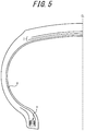
- FIG. 5 is a tire widthwise partially cross-sectional view of a pneumatic tire including the bead core according to the embodiment of the present disclosure in a bead portion.
- FIG. 5 only illustrates a tire widthwise half portion via a tire equatorial plane CL as a boundary, and another non-illustrated half portion also has a similar configuration.
- the pneumatic tire comprises the bead core 1 according to the embodiment of the present disclosure embedded in each of a pair of bead portions, and includes a belt 7 comprising two belt layers in the illustrated example on an outer side of a carcass 6 that toroidally straddles the bead core 1, in a tire radial direction.
- the non-linear interface 5 may have the apex 5a in the central portion of the annular body in the axial direction, and may be inclined from the apex 5a toward both ends of the bead core 1 in the axial direction and (e.g., linearly) to the other side of the annular body in the axial direction (outside in the axial direction).
- the non-linear interface 5 in the axial cross section of the annular body, in the axial cross section of the annular body, may have the apex 5a in the central portion of the annular body in the axial direction, and may be inclined from the apex 5a toward both ends of the bead core 1 in the axial direction and (e.g., linearly) to the other side of the annular body in the axial direction (outside in the axial direction).
- the interface 5 in the axial cross section of the annular body, has a substantially symmetric shape centered about the apex 5a in the axial direction of the annular body, but may be asymmetric.
- the non-linear interface 5 in the axial cross section of the annular body, may have a shape that is curved to have a center of curvature on the other side of the annular body in the radial direction (outside in the radial direction).
- the curvature of the curved shape is substantially constant, and the curvature may change.
- FIG. 3 the curvature of the curved shape is substantially constant, and the curvature may change.
- the non-linear interface 5 may have a shape that is curved to have the center of curvature on the other side of the annular body in the stack direction (outside in the radial direction) in the half portion of the annular body on one side in the axial direction, and curved to have the center of curvature on one side of the annular body in the stack direction (inside in the radial direction) in the half portion of the annular body on the other side in the axial direction.
- the non-linear interface 5 may have various shapes such as a zigzag shape and a wavy shape (also including a rectangular wavy shape). Additionally, in the present disclosure, a circumference of the annular body may further comprise a bead core coated with a coating resin.
- the upper side and the lower side have shapes that come in contact closely with each other in a case where the interface between the stacks adjacent to each other is superimposed on another interface.
- manufacturing is possible without generating any gap during the joining by the heat welding or the like, so that a joining strength can further increase. Furthermore, a positioning accuracy during the stacking increases, and variation in the manufacturing is therefore hard to be generated, so that quality improves.
Landscapes
- Engineering & Computer Science (AREA)
- Mechanical Engineering (AREA)
- Tires In General (AREA)
- Tyre Moulding (AREA)
Abstract
Description
- The present disclosure relates to a bead core, a manufacturing method of the same, and a pneumatic tire.
- Heretofore, a bead core comprising a bead wire coated with a coating resin has been suggested for a purpose of, for example, weight reduction of a member of a pneumatic tire (e.g., see PTL 1). In such a bead core, to decrease a winding count of the bead wire and thereby improve productivity, it is suggested that a strip member comprising one or more bead wires coated with a coating resin such as a thermoplastic resin is wound only in a stack direction and stacked to form an annular member. In this bead core, adjacent stacks of coating resins can be joined to each other, for example, by welding or bonding.
- PTL 1: Japanese Patent Laid-Open No.
2011-207157 - However, in the above technology, especially in a case where a stacked annular member is formed, there is concern that, for example, when a force such as a large lateral force acts on a tire, an interface of a coating resin between adjacent stacks peels off. Consequently, there is room for improvement of durability of a bead core in which a strip member coated with a coating resin is wound and stacked in a stack direction.
- To solve the problem, it is an object of the present disclosure to provide a bead core having a high durability, a pneumatic tire including the bead core in a bead portion, and a manufacturing method of the bead core by which such a bead core is obtainable.
- A gist configuration of the present disclosure is as follows.
- A bead core of the present disclosure is a bead core comprising an annular body in which a strip member comprising one or more bead wires coated with a coating resin is wound and stacked, wherein in an axial cross section of the annular body, an interface between stacks adjacent to each other is non-linear.
- A manufacturing method of a bead core of the present disclosure comprises an annular body forming step of winding and stacking a strip member comprising one or more bead wires coated with a coating resin to form an annular body, wherein the strip member has an upper side and a lower side in a cross section orthogonal to an extending direction of the strip member, and the upper side and the lower side are non-linear in the cross section.
- A pneumatic tire of the present disclosure comprises a bead portion, and comprises the above bead core in the bead portion.
- According to the present disclosure, there can be provided a bead core having a high durability, a pneumatic tire including a bead core in a bead portion, and a manufacturing method of the bead core by which such a bead core is obtainable.
- In the accompanying drawings:
-
FIG. 1 is an axial cross-sectional view of an annular body that forms a bead core according to an embodiment of the present disclosure; -
FIG. 2 is a schematic side view of the bead core according to the embodiment of the present disclosure; -
FIG. 3 is an axial cross-sectional view of an annular body that forms a bead core according to another embodiment of the present disclosure; -
FIG. 4 is an axial cross-sectional view of an annular body that forms a bead core according to still another embodiment of the present disclosure; and -
FIG. 5 is a tire widthwise partially cross-sectional view of a pneumatic tire including the bead core according to the embodiment of the present disclosure in a bead portion. - Hereinafter, embodiments of the present disclosure will be illustrated and described in detail with reference to the drawings.
-
FIG. 1 is an axial cross-sectional view of an annular body that forms a bead core according to an embodiment of the present disclosure. In the present embodiment, thisbead core 1 is configured as an annular body in which astrip member 4 comprising one or more (in an illustrated example, two)bead wires 2 coated with acoating resin 3 is wound and stacked (three stacks in this cross section). - In this example, the number of the
bead wires 2 to be arranged in an axial direction of the annular body is two in one stack ofstrip member 4, but the present disclosure is not especially limited to this case. The number of thebead wires 2 may be one or more. Furthermore, in the illustrated example, the annular body has a configuration in which three stacks are stacked in this cross section, but two or more stacks may be stacked. - In the
bead wire 2, an arbitrary known material can be used, and, for example, a steel cord can be used. The steel cord can comprise, for example, a steel monofilament or stranded wire. Furthermore, in thebead wire 2, organic fibers, carbon fibers or the like may be used. - Additionally, in a
coating resin 3, for example, a thermoplastic elastomer or a thermoplastic resin can be used, or a resin that crosslinks by heat or an electron beam or a resin that cures by thermal dislocation can be used. Examples of the thermoplastic elastomer include polyolefin thermoplastic elastomer (TPO), polystyrene thermoplastic elastomer (TPS), polyamide thermoplastic elastomer (TPA), polyurethane thermoplastic elastomer (TPU), polyester thermoplastic elastomer (TPC), and dynamic crosslinking thermoplastic elastomer (TPV). Furthermore, examples of the thermoplastic resin include polyurethane resin, polyolefin resin, vinyl chloride resin, and polyamide resin. Furthermore, as the thermoplastic resin, a resin can be used in which, for example, a deflection temperature under load (under a load of 0.45 MPa) prescribed in ISO75-2 or ASTM D648 is 78°C or more, a tensile yield strength prescribed in JIS K7113 is 10 MPa or more, a tensile rupture elongation (JIS K7113) similarly prescribed in JIS K7113 is 50% or more, and Vicat softening temperature (A-method) prescribed in JIS K7206 is 130°C or more. It is preferable that thecoating resin 3 that coats thebead wire 2 has a tensile elastic modulus (prescribed in JIS K7113: 1995) of 50 MPa or more. Furthermore, it is preferable that the tensile elastic modulus of thecoating resin 3 that coats thebead wire 2 is 1000 MPa or less. Note that thecoating resin 3 mentioned herein does not contain a rubber (an organic polymer material that exhibits a rubber elasticity at normal temperature). - In the
bead core 1 of the present embodiment, for example, mutual stacks have a state where thestrip member 4 is wound while melting thecoating resin 3 by hot plate welding or the like, and themolten coating resin 3 is solidified and joined. Alternatively, the stacks may be bonded and joined to each other with an adhesive or the like. -
FIG. 2 is a schematic side view of the bead core according to the embodiment of the present disclosure.FIG. 2 only illustrates thebead wire 2 for simplicity (FIG. 2 illustrates a center line of the bead wire 2), and omits depiction of thecoating resin 3. As illustrated inFIG. 2 , thebead wire 2 is spirally wound from a winding start end E1 about an axis O of the annular body in this cross-sectional view. F1, F2 and F3 indicate orbital positions, and in this example, a winding end edge E2 extends beyond at least a point F3. Therefore, when seen in an arbitrary radial position, three stacks or more of thebead wires 2 are stacked in this example. There are not any special restrictions on a length (an overlap length) of the bead wire from the orbital position (in this example, the point F3) located closest to a winding end edge E2 side to the winding end edge (in this example, a point E2). For example, the length can be from 1/200 to 199/200 of an orbital distance from a point F2 to the point F3. When the length is 1/200 or more of the orbital distance, an area where the coating resins come in contact with each other can increase between thebead wires 2 adjacent in a radial direction (a stack direction). Consequently, for example, adhesiveness or a welding force can be increased, and a tensile burden can be decreased. On the other hand, when the length is 199/200 or less of the orbital distance, the bead core can have a reduced weight. For similar reasons, the overlap length is preferably from 1/100 to 2/3 of the orbital distance from the point F2 to the point F3, and more preferably from 1/50 to 1/3 of the orbital distance from the point F2 to the point F3. - In the present embodiment, the
strip member 4 comprising one or morebead wires 2 coated with thecoating resin 3 is wound and stacked to form the annular body (an annular body forming step). In the present embodiment, thestrip member 4 is formed by coating an outer peripheral side of thebead wire 2 with themolten coating resin 3, and cooling and solidifying the resin. Furthermore, the annular body that forms thebead core 1 can be formed by winding and stacking thestrip member 4, and the stacks can be joined to each other, for example, by winding thestrip member 4 while melting thecoating resin 3 by the hot plate welding or the like, and solidifying themolten coating resin 3. Alternatively, the stacks can be joined by bonding the stacks to each other with the adhesive or the like. - In the
bead core 1 of the present embodiment, in an axial cross section of the annular body, an interface between stacks adjacent to each other is non-linear. Specifically, as illustrated inFIG. 1 , in the axial cross section of the annular body, anon-linear interface 5 has anapex 5a in a central portion (a center and a peripheral portion around the center, the center in the illustrated example) of the annular body in the axial direction, and is inclined linearly in this example from theapex 5a toward both ends of the annular body in the axial direction and to one side of the annular body in a radial direction (inside in the radial direction in this example). Further specifically, thestrip member 4 has an upper side and a lower side in this cross section, and the upper side and the lower side are non-linear in the cross section. Each of the upper side and the lower side has an apex in a central portion (a center and a peripheral portion around the center, the center in the illustrated example) of thestrip member 4 in a width direction, and is inclined linearly in this example from the apex toward both ends of thestrip member 4 in the width direction and to one side of thestrip member 4 in a thickness direction (illustrated downside in the thickness direction in this example). Note that thestrip member 4 has a cross-sectional shape formed in a desired shape using, for example, an extruder. - Hereinafter, description will be made as to operations and effects of the present embodiment.
- In the
bead core 1 of the present embodiment, as described above, in the axial cross section of the annular body, the interface between the stacks adjacent to each other is non-linear. Consequently, as compared with a case where the interface is linear, a joined area between the stacks is larger, and a joining force between the stacks is higher. - Therefore, also in a case where a force such as a large lateral force acts on the tire and shearing deformation occurs in the
bead core 1, thebead core 1 is hard to collapse, and durability of thebead core 1 can improve. - Furthermore, according to the present embodiment, in the axial cross section of the annular body, the
non-linear interface 5 has the apex 5a in the central portion of the annular body in the axial direction, and is inclined from the apex 5a toward both the ends of the annular body in the axial direction and to the one side of the annular body in the radial direction, especially to inside in the radial direction. Therefore, as compared with the case where the interface is linear, a cross-sectional secondary moment is larger. Due to an extracting force of the carcass under a tire load, thebead core 1 receives a rotating force. However, the bead core has a large cross-sectional secondary moment, has the inclination in a direction that hinders rotation, and is therefore hard to rotate. This can improve the durability of thebead core 1. - As above, the bead core of the present embodiment can have the improved durability.
- Furthermore, such nonlinearity can improve a positioning accuracy during manufacturing and stabilize quality.
-
FIG. 3 is an axial cross-sectional view of an annular body that forms a bead core according to another embodiment of the present disclosure. Also in an example illustrated inFIG. 3 , in an axial cross section of the annular body, aninterface 5 between stacks adjacent to each other is non-linear, but the interface has a shape different from that of the example illustrated inFIG. 1 . Specifically, as illustrated inFIG. 3 , in the axial cross section of the annular body, thenon-linear interface 5 has a shape that is curved to have a center of curvature on one side of the annular body in a radial direction (inside in the radial direction in this example). Further specifically, astrip member 4 has an upper side and a lower side in this cross section, and the upper side and the lower side are non-linear in this cross section. The upper side and lower side of thestrip member 4 have a shape that is curved to have a center of curvature on one side of thestrip member 4 in a thickness direction (illustrated downside in the thickness direction in this example). - Also in the other embodiment illustrated in
FIG. 3 , as compared with a case where the interface is linear, a joined area between the stacks is larger, and a joining force between the stacks is higher. Furthermore, as compared with the case where the interface is linear, a cross-sectional secondary moment is larger. Therefore, durability of abead core 1 can improve. -
FIG. 4 is an axial cross-sectional view of an annular body that forms a bead core according to still another embodiment of the present disclosure. Also in an example illustrated inFIG. 4 , in an axial cross section of the annular body, aninterface 5 between stacks adjacent to each other is non-linear, but the interface has a shape different from that of the example illustrated inFIG. 1 orFIG. 3 . Specifically, as illustrated inFIG. 4 , in the axial cross section of the annular body, thenon-linear interface 5 has a shape that is curved to have a center of curvature on one side of the annular body in a radial direction (inside in the radial direction in this example) in a half portion of the annular body on one side in an axial direction, and has a shape that is curved to have a center of curvature on the other side of the annular body in the radial direction (outside in the radial direction in this example) in another half portion of the annular body on the other side in the axial direction. Further specifically, astrip member 4 has an upper side and a lower side in this cross section, and the upper side and the lower side are non-linear in this cross section. The upper side and lower side of thestrip member 4 have a shape that is curved to have a center of curvature on one side of thestrip member 4 in a thickness direction (illustrated downside in the thickness direction in this example) in a half portion of thestrip member 4 on one side in a width direction, and have a shape that is curved to have a center of curvature on the other side of thestrip member 4 in the thickness direction (illustrated upside in the thickness direction in this example) in another half portion of thestrip member 4 on the other side in the width direction. - Also in the other embodiment illustrated in
FIG. 4 , as compared with a case where the interface is linear, a joined area between the stacks is larger, and a joining force between the stacks is higher. Therefore, durability of abead core 1 can improve. -
FIG. 5 is a tire widthwise partially cross-sectional view of a pneumatic tire including the bead core according to the embodiment of the present disclosure in a bead portion.FIG. 5 only illustrates a tire widthwise half portion via a tire equatorial plane CL as a boundary, and another non-illustrated half portion also has a similar configuration. As an example, as illustrated inFIG. 5 , the pneumatic tire comprises thebead core 1 according to the embodiment of the present disclosure embedded in each of a pair of bead portions, and includes abelt 7 comprising two belt layers in the illustrated example on an outer side of acarcass 6 that toroidally straddles thebead core 1, in a tire radial direction. - As above, the embodiments of the present disclosure have been described, but the present disclosure is not limited the above embodiments. For example, as a modification of the example illustrated in
FIG. 1 , in the axial cross section of the annular body, thenon-linear interface 5 may have the apex 5a in the central portion of the annular body in the axial direction, and may be inclined from the apex 5a toward both ends of thebead core 1 in the axial direction and (e.g., linearly) to the other side of the annular body in the axial direction (outside in the axial direction). Furthermore, in the example illustrated inFIG. 1 , in the axial cross section of the annular body, theinterface 5 has a substantially symmetric shape centered about the apex 5a in the axial direction of the annular body, but may be asymmetric. Furthermore, as a modification of the example illustrated inFIG. 3 , in the axial cross section of the annular body, thenon-linear interface 5 may have a shape that is curved to have a center of curvature on the other side of the annular body in the radial direction (outside in the radial direction). Additionally, in the example illustrated inFIG. 3 , the curvature of the curved shape is substantially constant, and the curvature may change. In addition, as a modification of the example illustrated inFIG. 4 , in the axial cross section of the annular body, thenon-linear interface 5 may have a shape that is curved to have the center of curvature on the other side of the annular body in the stack direction (outside in the radial direction) in the half portion of the annular body on one side in the axial direction, and curved to have the center of curvature on one side of the annular body in the stack direction (inside in the radial direction) in the half portion of the annular body on the other side in the axial direction. - Furthermore, in the axial cross section of the annular body, the
non-linear interface 5 may have various shapes such as a zigzag shape and a wavy shape (also including a rectangular wavy shape). Additionally, in the present disclosure, a circumference of the annular body may further comprise a bead core coated with a coating resin. - Additionally, it is preferable that the upper side and the lower side have shapes that come in contact closely with each other in a case where the interface between the stacks adjacent to each other is superimposed on another interface. In such forming as described above, manufacturing is possible without generating any gap during the joining by the heat welding or the like, so that a joining strength can further increase. Furthermore, a positioning accuracy during the stacking increases, and variation in the manufacturing is therefore hard to be generated, so that quality improves.
-
- 1
- bead core
- 2
- bead wire
- 3
- coating resin
- 4
- strip member
- 5
- interface
- 5a
- apex
- 6
- carcass
- 7
- belt
Claims (5)
- A bead core comprising an annular body in which a strip member comprising one or more bead wires coated with a coating resin is wound and stacked, wherein in an axial cross section of the annular body, an interface between stacks adjacent to each other is non-linear.
- The bead core according to claim 1, wherein in the axial cross section of the annular body, the non-linear interface has an apex in a central portion of the annular body in an axial direction, and is inclined from the apex toward both ends of the annular body in the axial direction and to one side of the annular body in a radial direction.
- A manufacturing method of a bead core, comprising an annular body forming step of winding and stacking a strip member comprising one or more bead wires coated with a coating resin to form an annular body, wherein the strip member has an upper side and a lower side in a cross section orthogonal to an extending direction of the strip member, and the upper side and the lower side are non-linear in the cross section.
- The manufacturing method of the bead core according to claim 3, wherein in the cross section, each of the upper side and the lower side has an apex in a central portion of the strip member in a width direction, and is inclined from the apex toward both ends of the strip member in the width direction and to one side of the strip member in a thickness direction.
- A pneumatic tire comprising a pair of bead portions, and comprising the bead core according to claim 1 or 2 in each of the bead portions.
Applications Claiming Priority (2)
| Application Number | Priority Date | Filing Date | Title |
|---|---|---|---|
| JP2017119964A JP2019001413A (en) | 2017-06-19 | 2017-06-19 | Bead core and manufacturing method thereof, pneumatic tire |
| PCT/JP2018/019712 WO2018235503A1 (en) | 2017-06-19 | 2018-05-22 | Bead core and method of manufacturing the same, pneumatic tire |
Publications (3)
| Publication Number | Publication Date |
|---|---|
| EP3643530A1 true EP3643530A1 (en) | 2020-04-29 |
| EP3643530A4 EP3643530A4 (en) | 2021-01-13 |
| EP3643530B1 EP3643530B1 (en) | 2023-03-08 |
Family
ID=64735748
Family Applications (1)
| Application Number | Title | Priority Date | Filing Date |
|---|---|---|---|
| EP18820415.0A Active EP3643530B1 (en) | 2017-06-19 | 2018-05-22 | Bead core, production method therefor, and pneumatic tire |
Country Status (5)
| Country | Link |
|---|---|
| US (1) | US20200207046A1 (en) |
| EP (1) | EP3643530B1 (en) |
| JP (1) | JP2019001413A (en) |
| CN (1) | CN110831785A (en) |
| WO (1) | WO2018235503A1 (en) |
Family Cites Families (14)
| Publication number | Priority date | Publication date | Assignee | Title |
|---|---|---|---|---|
| JPS551201A (en) * | 1978-02-28 | 1980-01-08 | Fuji Shoji Kk | Bead wire |
| JPS59145130A (en) * | 1983-02-08 | 1984-08-20 | Sumitomo Rubber Ind Ltd | Preparation of cast tire |
| FR2601294B1 (en) * | 1986-07-09 | 1988-11-10 | Michelin & Cie | ROD FOR TIRE COVERS INCLUDING RIBS; PROCESS FOR MAKING THIS TRINGLE; TIRE COVERS INCLUDING SUCH A PIPE. |
| US20040163748A1 (en) * | 2003-02-24 | 2004-08-26 | Kiyoshi Ueyoko | Tire having a composite belt structure |
| CN101072693B (en) * | 2005-01-25 | 2010-05-26 | 倍耐力轮胎股份公司 | Pneumatic tire with improved bead structure |
| JP5623736B2 (en) * | 2009-12-25 | 2014-11-12 | 株式会社ブリヂストン | Pneumatic tire |
| JP5588208B2 (en) | 2010-03-30 | 2014-09-10 | 株式会社ブリヂストン | Tire manufacturing method and tire |
| US9902121B2 (en) * | 2011-12-12 | 2018-02-27 | Bridgestone Corporation | Tire |
| US20130146201A1 (en) * | 2011-12-13 | 2013-06-13 | Jean-Louis Marie Félicien Thomas | Bead structure for a pneumatic tire |
| JP2013147051A (en) * | 2012-01-17 | 2013-08-01 | Bridgestone Corp | Bead core and tire using the same |
| US20150020944A1 (en) * | 2013-07-17 | 2015-01-22 | The Goodyear Tire & Rubber Company | Pneumatic tire having a single carcass ply reinforced with polyester cords |
| JP2016088259A (en) * | 2014-11-04 | 2016-05-23 | 東洋ゴム工業株式会社 | Pneumatic tire |
| CN204978113U (en) * | 2015-07-31 | 2016-01-20 | 查美富 | Tire bead core |
| WO2017061292A1 (en) * | 2015-10-07 | 2017-04-13 | 株式会社ブリヂストン | Tire |
-
2017
- 2017-06-19 JP JP2017119964A patent/JP2019001413A/en active Pending
-
2018
- 2018-05-22 EP EP18820415.0A patent/EP3643530B1/en active Active
- 2018-05-22 US US16/621,082 patent/US20200207046A1/en not_active Abandoned
- 2018-05-22 WO PCT/JP2018/019712 patent/WO2018235503A1/en not_active Ceased
- 2018-05-22 CN CN201880040913.2A patent/CN110831785A/en active Pending
Also Published As
| Publication number | Publication date |
|---|---|
| WO2018235503A1 (en) | 2018-12-27 |
| US20200207046A1 (en) | 2020-07-02 |
| EP3643530B1 (en) | 2023-03-08 |
| EP3643530A4 (en) | 2021-01-13 |
| CN110831785A (en) | 2020-02-21 |
| JP2019001413A (en) | 2019-01-10 |
Similar Documents
| Publication | Publication Date | Title |
|---|---|---|
| EP3176002A1 (en) | Tire | |
| EP3020571B1 (en) | Tire | |
| EP3643519A1 (en) | Pneumatic tire | |
| US20200047556A1 (en) | Tire | |
| EP3643529A1 (en) | Bead core, production method therefor, and pneumatic tire | |
| EP3643530B1 (en) | Bead core, production method therefor, and pneumatic tire | |
| EP1752315B1 (en) | Reinforcing air envelope for safety tire | |
| EP3643487A1 (en) | Pneumatic tire production method | |
| EP3643490B1 (en) | Bead core production method, bead core, and pneumatic tire | |
| EP3643531A1 (en) | Bead core | |
| EP3643486A1 (en) | Production method for pneumatic tire, and pneumatic tire | |
| US20210370725A1 (en) | Manufacturing method of bead core | |
| EP3677443B1 (en) | Tire with a clamped carcass ply | |
| US11207920B2 (en) | Pneumatic tire | |
| EP3643520A1 (en) | Pneumatic tire | |
| EP3643521A1 (en) | Pneumatic tire | |
| EP3643522A1 (en) | Pneumatic tire | |
| EP3812166A1 (en) | Pneumatic tire and production method for resin-coated belt | |
| EP3643518A1 (en) | Pneumatic tire | |
| WO2021117553A1 (en) | Tire | |
| WO2019239896A1 (en) | Tire and method for manufacturing belt layer structure member |
Legal Events
| Date | Code | Title | Description |
|---|---|---|---|
| STAA | Information on the status of an ep patent application or granted ep patent |
Free format text: STATUS: THE INTERNATIONAL PUBLICATION HAS BEEN MADE |
|
| PUAI | Public reference made under article 153(3) epc to a published international application that has entered the european phase |
Free format text: ORIGINAL CODE: 0009012 |
|
| STAA | Information on the status of an ep patent application or granted ep patent |
Free format text: STATUS: REQUEST FOR EXAMINATION WAS MADE |
|
| 17P | Request for examination filed |
Effective date: 20191216 |
|
| AK | Designated contracting states |
Kind code of ref document: A1 Designated state(s): AL AT BE BG CH CY CZ DE DK EE ES FI FR GB GR HR HU IE IS IT LI LT LU LV MC MK MT NL NO PL PT RO RS SE SI SK SM TR |
|
| AX | Request for extension of the european patent |
Extension state: BA ME |
|
| DAV | Request for validation of the european patent (deleted) | ||
| DAX | Request for extension of the european patent (deleted) | ||
| A4 | Supplementary search report drawn up and despatched |
Effective date: 20201211 |
|
| RIC1 | Information provided on ipc code assigned before grant |
Ipc: B29D 30/48 20060101ALI20201207BHEP Ipc: B60C 15/04 20060101AFI20201207BHEP |
|
| GRAP | Despatch of communication of intention to grant a patent |
Free format text: ORIGINAL CODE: EPIDOSNIGR1 |
|
| STAA | Information on the status of an ep patent application or granted ep patent |
Free format text: STATUS: GRANT OF PATENT IS INTENDED |
|
| INTG | Intention to grant announced |
Effective date: 20220922 |
|
| GRAS | Grant fee paid |
Free format text: ORIGINAL CODE: EPIDOSNIGR3 |
|
| GRAA | (expected) grant |
Free format text: ORIGINAL CODE: 0009210 |
|
| STAA | Information on the status of an ep patent application or granted ep patent |
Free format text: STATUS: THE PATENT HAS BEEN GRANTED |
|
| AK | Designated contracting states |
Kind code of ref document: B1 Designated state(s): AL AT BE BG CH CY CZ DE DK EE ES FI FR GB GR HR HU IE IS IT LI LT LU LV MC MK MT NL NO PL PT RO RS SE SI SK SM TR |
|
| REG | Reference to a national code |
Ref country code: CH Ref legal event code: EP Ref country code: AT Ref legal event code: REF Ref document number: 1552348 Country of ref document: AT Kind code of ref document: T Effective date: 20230315 |
|
| REG | Reference to a national code |
Ref country code: DE Ref legal event code: R096 Ref document number: 602018047055 Country of ref document: DE |
|
| REG | Reference to a national code |
Ref country code: IE Ref legal event code: FG4D |
|
| REG | Reference to a national code |
Ref country code: LT Ref legal event code: MG9D |
|
| P01 | Opt-out of the competence of the unified patent court (upc) registered |
Effective date: 20230526 |
|
| REG | Reference to a national code |
Ref country code: NL Ref legal event code: MP Effective date: 20230308 |
|
| PG25 | Lapsed in a contracting state [announced via postgrant information from national office to epo] |
Ref country code: RS Free format text: LAPSE BECAUSE OF FAILURE TO SUBMIT A TRANSLATION OF THE DESCRIPTION OR TO PAY THE FEE WITHIN THE PRESCRIBED TIME-LIMIT Effective date: 20230308 Ref country code: NO Free format text: LAPSE BECAUSE OF FAILURE TO SUBMIT A TRANSLATION OF THE DESCRIPTION OR TO PAY THE FEE WITHIN THE PRESCRIBED TIME-LIMIT Effective date: 20230608 Ref country code: LV Free format text: LAPSE BECAUSE OF FAILURE TO SUBMIT A TRANSLATION OF THE DESCRIPTION OR TO PAY THE FEE WITHIN THE PRESCRIBED TIME-LIMIT Effective date: 20230308 Ref country code: LT Free format text: LAPSE BECAUSE OF FAILURE TO SUBMIT A TRANSLATION OF THE DESCRIPTION OR TO PAY THE FEE WITHIN THE PRESCRIBED TIME-LIMIT Effective date: 20230308 Ref country code: HR Free format text: LAPSE BECAUSE OF FAILURE TO SUBMIT A TRANSLATION OF THE DESCRIPTION OR TO PAY THE FEE WITHIN THE PRESCRIBED TIME-LIMIT Effective date: 20230308 Ref country code: ES Free format text: LAPSE BECAUSE OF FAILURE TO SUBMIT A TRANSLATION OF THE DESCRIPTION OR TO PAY THE FEE WITHIN THE PRESCRIBED TIME-LIMIT Effective date: 20230308 |
|
| REG | Reference to a national code |
Ref country code: AT Ref legal event code: MK05 Ref document number: 1552348 Country of ref document: AT Kind code of ref document: T Effective date: 20230308 |
|
| PG25 | Lapsed in a contracting state [announced via postgrant information from national office to epo] |
Ref country code: SE Free format text: LAPSE BECAUSE OF FAILURE TO SUBMIT A TRANSLATION OF THE DESCRIPTION OR TO PAY THE FEE WITHIN THE PRESCRIBED TIME-LIMIT Effective date: 20230308 Ref country code: NL Free format text: LAPSE BECAUSE OF FAILURE TO SUBMIT A TRANSLATION OF THE DESCRIPTION OR TO PAY THE FEE WITHIN THE PRESCRIBED TIME-LIMIT Effective date: 20230308 Ref country code: GR Free format text: LAPSE BECAUSE OF FAILURE TO SUBMIT A TRANSLATION OF THE DESCRIPTION OR TO PAY THE FEE WITHIN THE PRESCRIBED TIME-LIMIT Effective date: 20230609 Ref country code: FI Free format text: LAPSE BECAUSE OF FAILURE TO SUBMIT A TRANSLATION OF THE DESCRIPTION OR TO PAY THE FEE WITHIN THE PRESCRIBED TIME-LIMIT Effective date: 20230308 |
|
| PG25 | Lapsed in a contracting state [announced via postgrant information from national office to epo] |
Ref country code: SM Free format text: LAPSE BECAUSE OF FAILURE TO SUBMIT A TRANSLATION OF THE DESCRIPTION OR TO PAY THE FEE WITHIN THE PRESCRIBED TIME-LIMIT Effective date: 20230308 Ref country code: RO Free format text: LAPSE BECAUSE OF FAILURE TO SUBMIT A TRANSLATION OF THE DESCRIPTION OR TO PAY THE FEE WITHIN THE PRESCRIBED TIME-LIMIT Effective date: 20230308 Ref country code: PT Free format text: LAPSE BECAUSE OF FAILURE TO SUBMIT A TRANSLATION OF THE DESCRIPTION OR TO PAY THE FEE WITHIN THE PRESCRIBED TIME-LIMIT Effective date: 20230710 Ref country code: EE Free format text: LAPSE BECAUSE OF FAILURE TO SUBMIT A TRANSLATION OF THE DESCRIPTION OR TO PAY THE FEE WITHIN THE PRESCRIBED TIME-LIMIT Effective date: 20230308 Ref country code: CZ Free format text: LAPSE BECAUSE OF FAILURE TO SUBMIT A TRANSLATION OF THE DESCRIPTION OR TO PAY THE FEE WITHIN THE PRESCRIBED TIME-LIMIT Effective date: 20230308 Ref country code: AT Free format text: LAPSE BECAUSE OF FAILURE TO SUBMIT A TRANSLATION OF THE DESCRIPTION OR TO PAY THE FEE WITHIN THE PRESCRIBED TIME-LIMIT Effective date: 20230308 |
|
| PG25 | Lapsed in a contracting state [announced via postgrant information from national office to epo] |
Ref country code: SK Free format text: LAPSE BECAUSE OF FAILURE TO SUBMIT A TRANSLATION OF THE DESCRIPTION OR TO PAY THE FEE WITHIN THE PRESCRIBED TIME-LIMIT Effective date: 20230308 Ref country code: PL Free format text: LAPSE BECAUSE OF FAILURE TO SUBMIT A TRANSLATION OF THE DESCRIPTION OR TO PAY THE FEE WITHIN THE PRESCRIBED TIME-LIMIT Effective date: 20230308 Ref country code: IS Free format text: LAPSE BECAUSE OF FAILURE TO SUBMIT A TRANSLATION OF THE DESCRIPTION OR TO PAY THE FEE WITHIN THE PRESCRIBED TIME-LIMIT Effective date: 20230708 |
|
| REG | Reference to a national code |
Ref country code: DE Ref legal event code: R097 Ref document number: 602018047055 Country of ref document: DE |
|
| REG | Reference to a national code |
Ref country code: CH Ref legal event code: PL |
|
| PLBE | No opposition filed within time limit |
Free format text: ORIGINAL CODE: 0009261 |
|
| STAA | Information on the status of an ep patent application or granted ep patent |
Free format text: STATUS: NO OPPOSITION FILED WITHIN TIME LIMIT |
|
| PG25 | Lapsed in a contracting state [announced via postgrant information from national office to epo] |
Ref country code: MC Free format text: LAPSE BECAUSE OF FAILURE TO SUBMIT A TRANSLATION OF THE DESCRIPTION OR TO PAY THE FEE WITHIN THE PRESCRIBED TIME-LIMIT Effective date: 20230308 |
|
| REG | Reference to a national code |
Ref country code: BE Ref legal event code: MM Effective date: 20230531 |
|
| PG25 | Lapsed in a contracting state [announced via postgrant information from national office to epo] |
Ref country code: SI Free format text: LAPSE BECAUSE OF FAILURE TO SUBMIT A TRANSLATION OF THE DESCRIPTION OR TO PAY THE FEE WITHIN THE PRESCRIBED TIME-LIMIT Effective date: 20230308 Ref country code: MC Free format text: LAPSE BECAUSE OF FAILURE TO SUBMIT A TRANSLATION OF THE DESCRIPTION OR TO PAY THE FEE WITHIN THE PRESCRIBED TIME-LIMIT Effective date: 20230308 Ref country code: LU Free format text: LAPSE BECAUSE OF NON-PAYMENT OF DUE FEES Effective date: 20230522 Ref country code: LI Free format text: LAPSE BECAUSE OF NON-PAYMENT OF DUE FEES Effective date: 20230531 Ref country code: DK Free format text: LAPSE BECAUSE OF FAILURE TO SUBMIT A TRANSLATION OF THE DESCRIPTION OR TO PAY THE FEE WITHIN THE PRESCRIBED TIME-LIMIT Effective date: 20230308 Ref country code: CH Free format text: LAPSE BECAUSE OF NON-PAYMENT OF DUE FEES Effective date: 20230531 |
|
| 26N | No opposition filed |
Effective date: 20231211 |
|
| GBPC | Gb: european patent ceased through non-payment of renewal fee |
Effective date: 20230608 |
|
| REG | Reference to a national code |
Ref country code: IE Ref legal event code: MM4A |
|
| PG25 | Lapsed in a contracting state [announced via postgrant information from national office to epo] |
Ref country code: IE Free format text: LAPSE BECAUSE OF NON-PAYMENT OF DUE FEES Effective date: 20230522 |
|
| PG25 | Lapsed in a contracting state [announced via postgrant information from national office to epo] |
Ref country code: IE Free format text: LAPSE BECAUSE OF NON-PAYMENT OF DUE FEES Effective date: 20230522 Ref country code: GB Free format text: LAPSE BECAUSE OF NON-PAYMENT OF DUE FEES Effective date: 20230608 |
|
| PG25 | Lapsed in a contracting state [announced via postgrant information from national office to epo] |
Ref country code: IT Free format text: LAPSE BECAUSE OF FAILURE TO SUBMIT A TRANSLATION OF THE DESCRIPTION OR TO PAY THE FEE WITHIN THE PRESCRIBED TIME-LIMIT Effective date: 20230308 Ref country code: BE Free format text: LAPSE BECAUSE OF NON-PAYMENT OF DUE FEES Effective date: 20230531 |
|
| PG25 | Lapsed in a contracting state [announced via postgrant information from national office to epo] |
Ref country code: BG Free format text: LAPSE BECAUSE OF FAILURE TO SUBMIT A TRANSLATION OF THE DESCRIPTION OR TO PAY THE FEE WITHIN THE PRESCRIBED TIME-LIMIT Effective date: 20230308 |
|
| PG25 | Lapsed in a contracting state [announced via postgrant information from national office to epo] |
Ref country code: BG Free format text: LAPSE BECAUSE OF FAILURE TO SUBMIT A TRANSLATION OF THE DESCRIPTION OR TO PAY THE FEE WITHIN THE PRESCRIBED TIME-LIMIT Effective date: 20230308 |
|
| PG25 | Lapsed in a contracting state [announced via postgrant information from national office to epo] |
Ref country code: CY Free format text: LAPSE BECAUSE OF FAILURE TO SUBMIT A TRANSLATION OF THE DESCRIPTION OR TO PAY THE FEE WITHIN THE PRESCRIBED TIME-LIMIT; INVALID AB INITIO Effective date: 20180522 |
|
| PG25 | Lapsed in a contracting state [announced via postgrant information from national office to epo] |
Ref country code: HU Free format text: LAPSE BECAUSE OF FAILURE TO SUBMIT A TRANSLATION OF THE DESCRIPTION OR TO PAY THE FEE WITHIN THE PRESCRIBED TIME-LIMIT; INVALID AB INITIO Effective date: 20180522 |
|
| PG25 | Lapsed in a contracting state [announced via postgrant information from national office to epo] |
Ref country code: TR Free format text: LAPSE BECAUSE OF FAILURE TO SUBMIT A TRANSLATION OF THE DESCRIPTION OR TO PAY THE FEE WITHIN THE PRESCRIBED TIME-LIMIT Effective date: 20230308 |
|
| PGFP | Annual fee paid to national office [announced via postgrant information from national office to epo] |
Ref country code: DE Payment date: 20260522 Year of fee payment: 9 |
|
| PGFP | Annual fee paid to national office [announced via postgrant information from national office to epo] |
Ref country code: FR Payment date: 20260526 Year of fee payment: 9 |