EP3643466A1 - Machine tool for machining panels and method - Google Patents
Machine tool for machining panels and method Download PDFInfo
- Publication number
- EP3643466A1 EP3643466A1 EP19202185.5A EP19202185A EP3643466A1 EP 3643466 A1 EP3643466 A1 EP 3643466A1 EP 19202185 A EP19202185 A EP 19202185A EP 3643466 A1 EP3643466 A1 EP 3643466A1
- Authority
- EP
- European Patent Office
- Prior art keywords
- axis
- constraint member
- border
- contact element
- panel
- Prior art date
- Legal status (The legal status is an assumption and is not a legal conclusion. Google has not performed a legal analysis and makes no representation as to the accuracy of the status listed.)
- Granted
Links
Images



Classifications
-
- B—PERFORMING OPERATIONS; TRANSPORTING
- B27—WORKING OR PRESERVING WOOD OR SIMILAR MATERIAL; NAILING OR STAPLING MACHINES IN GENERAL
- B27C—PLANING, DRILLING, MILLING, TURNING OR UNIVERSAL MACHINES FOR WOOD OR SIMILAR MATERIAL
- B27C3/00—Drilling machines or drilling devices; Equipment therefor
-
- B—PERFORMING OPERATIONS; TRANSPORTING
- B27—WORKING OR PRESERVING WOOD OR SIMILAR MATERIAL; NAILING OR STAPLING MACHINES IN GENERAL
- B27C—PLANING, DRILLING, MILLING, TURNING OR UNIVERSAL MACHINES FOR WOOD OR SIMILAR MATERIAL
- B27C5/00—Machines designed for producing special profiles or shaped work, e.g. by rotary cutters; Equipment therefor
- B27C5/02—Machines with table
- B27C5/06—Arrangements for clamping or feeding work
-
- B—PERFORMING OPERATIONS; TRANSPORTING
- B23—MACHINE TOOLS; METAL-WORKING NOT OTHERWISE PROVIDED FOR
- B23Q—DETAILS, COMPONENTS, OR ACCESSORIES FOR MACHINE TOOLS, e.g. ARRANGEMENTS FOR COPYING OR CONTROLLING; MACHINE TOOLS IN GENERAL CHARACTERISED BY THE CONSTRUCTION OF PARTICULAR DETAILS OR COMPONENTS; COMBINATIONS OR ASSOCIATIONS OF METAL-WORKING MACHINES, NOT DIRECTED TO A PARTICULAR RESULT
- B23Q1/00—Members which are comprised in the general build-up of a form of machine, particularly relatively large fixed members
- B23Q1/03—Stationary work or tool supports
- B23Q1/037—Stationary work or tool supports comprising series of support elements whose relative distance is adjustable
-
- B—PERFORMING OPERATIONS; TRANSPORTING
- B23—MACHINE TOOLS; METAL-WORKING NOT OTHERWISE PROVIDED FOR
- B23Q—DETAILS, COMPONENTS, OR ACCESSORIES FOR MACHINE TOOLS, e.g. ARRANGEMENTS FOR COPYING OR CONTROLLING; MACHINE TOOLS IN GENERAL CHARACTERISED BY THE CONSTRUCTION OF PARTICULAR DETAILS OR COMPONENTS; COMBINATIONS OR ASSOCIATIONS OF METAL-WORKING MACHINES, NOT DIRECTED TO A PARTICULAR RESULT
- B23Q16/00—Equipment for precise positioning of tool or work into particular locations not otherwise provided for
- B23Q16/001—Stops, cams, or holders therefor
-
- B—PERFORMING OPERATIONS; TRANSPORTING
- B23—MACHINE TOOLS; METAL-WORKING NOT OTHERWISE PROVIDED FOR
- B23Q—DETAILS, COMPONENTS, OR ACCESSORIES FOR MACHINE TOOLS, e.g. ARRANGEMENTS FOR COPYING OR CONTROLLING; MACHINE TOOLS IN GENERAL CHARACTERISED BY THE CONSTRUCTION OF PARTICULAR DETAILS OR COMPONENTS; COMBINATIONS OR ASSOCIATIONS OF METAL-WORKING MACHINES, NOT DIRECTED TO A PARTICULAR RESULT
- B23Q3/00—Devices holding, supporting, or positioning work or tools, of a kind normally removable from the machine
- B23Q3/18—Devices holding, supporting, or positioning work or tools, of a kind normally removable from the machine for positioning only
-
- B—PERFORMING OPERATIONS; TRANSPORTING
- B27—WORKING OR PRESERVING WOOD OR SIMILAR MATERIAL; NAILING OR STAPLING MACHINES IN GENERAL
- B27C—PLANING, DRILLING, MILLING, TURNING OR UNIVERSAL MACHINES FOR WOOD OR SIMILAR MATERIAL
- B27C9/00—Multi-purpose machines; Universal machines; Equipment therefor
Definitions
- This invention relates to a machine tool for machining panels.
- the invention relates to a machine tool for performing machining operations, preferably drilling and/or milling operations, on panels made of wood or other material.
- the overall size of the grippers makes the positioning of the operating units in some zones of the machine adjacent to the panel problematic, limiting the relative flexibility of use.
- the grippers are configured in such a way as to grip the panel by friction on its upper and lower faces, with the consequent risk of causing permanent marks on its surface.
- This operation can also limit the final precision of the machining.
- the locking occurs by means of contrasting corner elements, that is to say, in contact, acting on two right-angled sides of the panel, and, therefore, not by friction on the upper and lower faces of the panels.
- the constrain members provided since they are angular in shape, cannot move with respect to the panel from the respective gripping position without detaching from the panel itself.
- the aim of the invention is therefore to provide a machine tool for machining panels equipped with a system for gripping and moving panels to be machined which allows a high flexibility of use in terms of possibility of movement of the operating means designed for machining the panel.
- Another aim of the invention is to provide a machine tool for machining panels equipped with a system for gripping and moving panels to be machined which has reduced dimensions.
- Another aim of the invention is to provide a machine tool for machining panels equipped with a system for gripping and moving panels to be machined which allows, during machining, modifying the gripping position on the panel without losing the reference of the panel in order to free the area occupied and allow the machining.
- the specific object of this invention is therefore a machine tool for machining panels comprising: operating means for the performance of at least one machining operation on a panel lying on a predetermined surface defined by a first axis and a second axis, in said panel being defined a front border, a rear border opposite said front border, a first side border and a second side border opposite said first side border; a stopping and moving system for stopping and moving said panel on said predetermined surface, said stopping and moving system comprising: a first lateral contact element and a second lateral contact element movable according to said first axis and configured to make contact, in use, with, respectively, said first side border and said second side border causing the locking of said panel with respect to said first axis; a first front constraint member and a second front constraint member moveable according to said first axis and said second axis and configured to make contact, in use, with said front border causing a constraint to the movement of said panel in a first direction according to said second axis; and a
- said stopping and moving system comprises a first guide and a second guide which are movable according to said first axis, where said first front constraint member and first rear constraint member are connected with said first guide in a movable way according to said second axis, and where said second front constraint member and said second rear constraint member are connected with said second guide in a movable way according to said second axis.
- said first guide and said second guide are substantially parallel to said second axis.
- said first lateral contact element can be connected with said first guide in a movable way according to said second axis
- said second lateral contact element can be connected with said second guide in a movable way according to said second axis.
- said first lateral contact element can be rigidly connected with said first guide and said second lateral contact element can be rigidly connected with said second guide.
- said first lateral contact element and said second lateral contact element can have an oblong shape extending according to said first axis.
- said first front constraint member, said second front constraint member, said first rear constraint member and said second rear constraint member can comprise a device which is movable according to said first axis.
- said device can comprise a contact element which is configured to come in contact, in use, with said panel, said contact element having an oblong shape and being movable according to said first axis and oriented substantially according to said second axis.
- the specific object of this invention is also a method for machining, using a machine tool as indicated above, a panel having an upper face, a front border, a rear border opposite and parallel to said front border, a first side border and a second side border opposite and parallel to said first side border, wherein said first side border forms with said front border and said rear border, respectively, a first acute angle and a first obtuse angle and wherein said second side border forms with said front order and said rear border, respectively, a second obtuse angle and a second acute angle, said method comprising the following steps: placing said panel between said first lateral contact element, said second lateral contact element, said first front constraint member, said second front constraint member, said first rear constraint member and said second rear constraint member; detecting at least the position of said first side border or said second side border by, respectively, said first lateral contact element or said second lateral contact element; jointly moving said first front constraint member and said first rear constraint member or said second front constraint member and said second rear constraint member
- the numeral 1 indicates a first machine tool for machining panels according to a first embodiment of the invention.
- the machine tool 1 comprises a base 2 above which is provided a working surface 3 lying, substantially, on a horizontal surface defined by a first axis X and a second axis Y at right angles to said first axis X.
- a stopping and moving system 4 to allow the stopping and moving of the panels on the above-mentioned horizontal surface during the execution of the machining operations planned on the latter.
- the stopping and moving system 4 in turn comprises a first linear guide 5a and a second linear guide 5b parallel to each other and both oriented according to the above-mentioned second axis Y.
- Both the first linear guide 5a and the second linear guide 5b are movable along said first axis X independently from each other thanks, respectively, to a first motor 6a and a second motor 6b.
- the same stopping and moving system 4 also comprises a first front constraint member 7a enabled to move along the first linear guide 5a thanks to a third motor 8a, and a second front constraint member 7b enabled to move along the second linear guide 5b thanks to a fourth motor 8b.
- the first front constraint member 7a and the second front constraint member 7b comprise, respectively, a first telescopic device 9a and a second telescopic device 9b which are both movable according to the first axis X and are equipped, respectively, with a first front contact end element 10a and a second front contact end element 10b (see Figure 4 ) oriented according to the above-mentioned second axis Y and designed to come into contact, in use, with the front border F of the panel P.
- the stopping and moving system 4 also includes a first rear constraint member 11a enabled to move along the first linear guide 5a thanks to a fifth motor 12a, and a second rear constraint member 11b enabled to move along the second linear guide 5b thanks to a sixth motor 12b.
- the first rear constraint member 11a and the second rear constraint member 11b comprise, respectively, a third telescopic device 13a and a fourth telescopic device 13b, both movable according to the first axis X.
- the third telescopic device 13a and the fourth telescopic device 13b are also equipped, respectively, with a first rear contact end element 14a and a second rear contact end element 14b oriented according to the above-mentioned axis Y and designed to come into contact, in use, with the rear border R of the panel P.
- the stopping and moving system 4 also includes a first lateral constraint member 15a enabled to move along the first linear guide 5a thanks to a seventh motor 16a, and a second lateral constraint member 15b enabled to move along the second linear guide 5b thanks to a sixth motor 16b.
- the first lateral constraint element 15a and the second lateral constraint element 15b are respectively equipped with a first lateral contact element 17a and a second lateral contact element 17b which are both oriented along the first axis X and designed to make contact, in use, with, respectively, a first side border M of the panel and a second side border N of the same panel P, opposite said first side border M.
- an operating head 18 that is to say, an operating device movable with respect to the work surface 3 and designed to execute one or more machining operations, such as, for example, drilling operations, on the panel P.
- the same machine tool 1 can also comprise, even though not shown in Figures 1-6 , other operational devices for performing further machining operations on the panel P.
- the latter is placed in a zone of the working surface 3 between the first front constraint member 7a, the second front constraint member 7b, the first rear constraint member 11a, the second rear constraint member 11b, the first lateral constraint member 15a and the second lateral constraint member 15b, as shown in Figure 4 .
- the same panel P is locked by moving the first front constraint member 7a and the second front constraint member 7b in contact with the front border F, the first rear constraint member 11a and the second rear constraint member 11b in contact with the rear border R, and the first lateral constraint member 15a and the second lateral constraint member 15b in contact, respectively, with the first side border M and the second side border N of the panel P.
- the first lateral constraint member 15a or the second lateral constraint member 15b along the second axis Y to leave the machining area free or, alternatively, move the panel P along the second axis Y moving, in an integral fashion, the first lateral contact element 7a, the second lateral contact element 7b, the first rear constraint member 11a and the second rear constraint member 11b along the second axis Y.
- Figures 5 and 6 show, on the other hand, a particular functionality of the same machine tool 1, which can be actuated in the case of machining operations on panels with a squaring error P', that is to say, panels with sides which are not perfectly at right angles to each other and opposite sides parallel.
- first lateral contact element 17a of the first lateral constraint member 15a and/or the second lateral contact element 17b of the second lateral constraint member 15b make contact with the first side border M' and/or the second side border N' in order to detect the exact position.
- the first front constraint member 7a and the first rear constraint member 11a are translated, in an integral fashion, along the second axis Y and/or the second front constraint member 7b and the second rear constraint member 11b are translated, in an integral fashion, again along the second axis Y in such a way that the panel P' rotates by an angle such as to allow the relative side borders M', N' to orient parallel to the second axis Y (see Figure 6 ).
- the panel P' is in a position suitable for the execution of the above-mentioned structural holes.
- Figures 7 and 8 show, on the other hand, a second tool machine 1' according to the invention, which is identical to the first tool machine 1 described above with the exception of the fact that the first lateral contact element 17a' and the second lateral contact element 17b' are in this case rigidly connected, respectively, to the first linear guide 5a' and to the second linear guide 5b', without being able to move along the second axis Y.
- the second machine tool 1' therefore represents, in fact, a simplified version of the first machine tool 1.
- the machine tool according to the invention has a high degree of flexibility of use, at the same time allowing the performance of high precision machining operations.
Landscapes
- Life Sciences & Earth Sciences (AREA)
- Engineering & Computer Science (AREA)
- Mechanical Engineering (AREA)
- Wood Science & Technology (AREA)
- Forests & Forestry (AREA)
- Machine Tool Units (AREA)
- Drilling And Boring (AREA)
Abstract
Description
- This invention relates to a machine tool for machining panels.
- More in detail, the invention relates to a machine tool for performing machining operations, preferably drilling and/or milling operations, on panels made of wood or other material.
- The description below relates to drilling and milling operations, but it is quite apparent how the same should not be considered limited to this specific use, as the machine tool according to the invention may also be applied for the performance of other types of machining operations.
- There are several prior art machine tools for drilling panels equipped with systems for gripping and linear movement of the panels to be machined.
- However, these machines have various technical limitations both in terms of flexibility in the use of the operating units and in terms of possible marks being made on the panel being machined on the gripping surfaces of the grippers of the gripping system.
- In fact, the overall size of the grippers makes the positioning of the operating units in some zones of the machine adjacent to the panel problematic, limiting the relative flexibility of use.
- Moreover, the grippers are configured in such a way as to grip the panel by friction on its upper and lower faces, with the consequent risk of causing permanent marks on its surface.
- With this type of stopping and moving system there is also the possibility that, during the machining of the panel, it is necessary to change the gripping position in order to free the zones of the panel covered by the gripping system.
- This operation, as well as increasing the machining times of the piece, can also limit the final precision of the machining.
- There are also other types of machine tools for drilling panels comprising particular grippers equipped with long arms with small thicknesses, which block the panel to be machined by acting on the relative corners.
- In this case, the locking occurs by means of contrasting corner elements, that is to say, in contact, acting on two right-angled sides of the panel, and, therefore, not by friction on the upper and lower faces of the panels.
- However, this last solution of machine tool presented generally has significant overall dimensions.
- Moreover, the constrain members provided, since they are angular in shape, cannot move with respect to the panel from the respective gripping position without detaching from the panel itself.
- Therefore, in these cases, in order to allow the execution of machining operations in the corner zones of the panels, it is necessary to temporarily separate the corner constraining members from the panel and lock the latter by means of further constraining members until the completion of the machining operations planned in those zones.
- In light of the above, the aim of the invention is therefore to provide a machine tool for machining panels equipped with a system for gripping and moving panels to be machined which allows a high flexibility of use in terms of possibility of movement of the operating means designed for machining the panel.
- Another aim of the invention is to provide a machine tool for machining panels equipped with a system for gripping and moving panels to be machined which has reduced dimensions.
- Another aim of the invention is to provide a machine tool for machining panels equipped with a system for gripping and moving panels to be machined which allows, during machining, modifying the gripping position on the panel without losing the reference of the panel in order to free the area occupied and allow the machining.
- The specific object of this invention is therefore a machine tool for machining panels comprising: operating means for the performance of at least one machining operation on a panel lying on a predetermined surface defined by a first axis and a second axis, in said panel being defined a front border, a rear border opposite said front border, a first side border and a second side border opposite said first side border; a stopping and moving system for stopping and moving said panel on said predetermined surface, said stopping and moving system comprising: a first lateral contact element and a second lateral contact element movable according to said first axis and configured to make contact, in use, with, respectively, said first side border and said second side border causing the locking of said panel with respect to said first axis; a first front constraint member and a second front constraint member moveable according to said first axis and said second axis and configured to make contact, in use, with said front border causing a constraint to the movement of said panel in a first direction according to said second axis; and a first rear constraint member and a second rear constraint member movable according to said first axis and said second axis and configured to make contact, in use, with said rear border causing a constraint to the movement of said panel in a second direction according to said second axis opposite said first direction; wherein said first front constraint member, said second front constraint member, said first rear constraint member and said second rear constraint member are movable independently of said first lateral contact element and said second lateral contact element in such a way as to allow, in use, said operating means to operate on any zone of said front border, said rear border, said first side border and said second side border maintaining said first lateral contact element, said second lateral contact element, said first front constraint member, said second front constraint member, said first rear constraint member and said second rear constraint member in contact with said panel.
- Preferably, according to the invention, said stopping and moving system comprises a first guide and a second guide which are movable according to said first axis, where said first front constraint member and first rear constraint member are connected with said first guide in a movable way according to said second axis, and where said second front constraint member and said second rear constraint member are connected with said second guide in a movable way according to said second axis.
- Advantageously, according to the invention, said first guide and said second guide are substantially parallel to said second axis.
- Further, according to the invention, said first lateral contact element can be connected with said first guide in a movable way according to said second axis, and said second lateral contact element can be connected with said second guide in a movable way according to said second axis.
- Alternatively, according to the invention, said first lateral contact element can be rigidly connected with said first guide and said second lateral contact element can be rigidly connected with said second guide.
- Moreover, according to the invention, said first lateral contact element and said second lateral contact element can have an oblong shape extending according to said first axis.
- Conveniently, according to the invention, said first front constraint member, said second front constraint member, said first rear constraint member and said second rear constraint member can comprise a device which is movable according to said first axis.
- Further, according to the invention, said device can comprise a contact element which is configured to come in contact, in use, with said panel, said contact element having an oblong shape and being movable according to said first axis and oriented substantially according to said second axis.
- The specific object of this invention is also a method for machining, using a machine tool as indicated above, a panel having an upper face, a front border, a rear border opposite and parallel to said front border, a first side border and a second side border opposite and parallel to said first side border, wherein said first side border forms with said front border and said rear border, respectively, a first acute angle and a first obtuse angle and wherein said second side border forms with said front order and said rear border, respectively, a second obtuse angle and a second acute angle, said method comprising the following steps: placing said panel between said first lateral contact element, said second lateral contact element, said first front constraint member, said second front constraint member, said first rear constraint member and said second rear constraint member; detecting at least the position of said first side border or said second side border by, respectively, said first lateral contact element or said second lateral contact element; jointly moving said first front constraint member and said first rear constraint member or said second front constraint member and said second rear constraint member along said second axis in such a way that said first side border and said second side border are parallel to said second axis; and executing on said upper face at least one row of holes parallel to said second axis, wherein said holes are oriented according to a third axis at right angles to said first axis and said second axis, in such a way that said at least one row of holes is parallel to said first side border and to said second side border.
- The invention is now described, by way of example and without limiting the scope of the invention, with reference to the accompanying drawings which illustrate preferred embodiments of it, in which:
- -
Figure 1 is an overall axonometric view of a machine tool according to a first embodiment of the invention; -
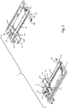
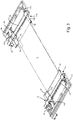
Figure 2 is an axonometric view of the gripping system provided in the machine shown inFigure 1 ; -
Figure 3 is an axonometric view of the gripping system ofFigure 2 , associated with a panel; -
Figure 4 is a partial schematic top plan view of the machine tool shown inFigure 1 ; -
Figure 5 is a partial schematic top plan view of the machine tool shown inFigures 1 and4 , associated with a panel with a squaring error, according to a first operating configuration; -
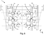
Figure 6 is a partial schematic top plan view of the machine tool shown inFigures 1 ,4 and 5 , associated with a panel with a squaring error, according to a second operating configuration; -
Figure 7 is a partial schematic top plan view of a machine tool according to a second embodiment of the invention; and -
Figure 8 is a partial schematic top plan view of the machine tool shown inFigure 7 , in a second operating step. - The similar parts will be indicated in the various drawings with the same numerical references.
- With reference to
Figures 1 to 6 , thenumeral 1 indicates a first machine tool for machining panels according to a first embodiment of the invention. - The
machine tool 1 comprises abase 2 above which is provided a workingsurface 3 lying, substantially, on a horizontal surface defined by a first axis X and a second axis Y at right angles to said first axis X. - On the
work surface 3 there is a stopping and movingsystem 4 to allow the stopping and moving of the panels on the above-mentioned horizontal surface during the execution of the machining operations planned on the latter. - The stopping and moving
system 4 in turn comprises a firstlinear guide 5a and a secondlinear guide 5b parallel to each other and both oriented according to the above-mentioned second axis Y. - Both the first
linear guide 5a and the secondlinear guide 5b are movable along said first axis X independently from each other thanks, respectively, to afirst motor 6a and asecond motor 6b. - The same stopping and moving
system 4 also comprises a firstfront constraint member 7a enabled to move along the firstlinear guide 5a thanks to athird motor 8a, and a secondfront constraint member 7b enabled to move along the secondlinear guide 5b thanks to afourth motor 8b. - The first
front constraint member 7a and the secondfront constraint member 7b comprise, respectively, a firsttelescopic device 9a and a secondtelescopic device 9b which are both movable according to the first axis X and are equipped, respectively, with a first frontcontact end element 10a and a second frontcontact end element 10b (seeFigure 4 ) oriented according to the above-mentioned second axis Y and designed to come into contact, in use, with the front border F of the panel P. - The stopping and moving
system 4 also includes a firstrear constraint member 11a enabled to move along the firstlinear guide 5a thanks to afifth motor 12a, and a secondrear constraint member 11b enabled to move along the secondlinear guide 5b thanks to asixth motor 12b. - The first
rear constraint member 11a and the secondrear constraint member 11b comprise, respectively, a thirdtelescopic device 13a and a fourthtelescopic device 13b, both movable according to the first axis X. - The third
telescopic device 13a and the fourthtelescopic device 13b are also equipped, respectively, with a first rearcontact end element 14a and a second rearcontact end element 14b oriented according to the above-mentioned axis Y and designed to come into contact, in use, with the rear border R of the panel P. - The stopping and moving
system 4 also includes a firstlateral constraint member 15a enabled to move along the firstlinear guide 5a thanks to aseventh motor 16a, and a secondlateral constraint member 15b enabled to move along the secondlinear guide 5b thanks to asixth motor 16b. - The first
lateral constraint element 15a and the secondlateral constraint element 15b are respectively equipped with a firstlateral contact element 17a and a secondlateral contact element 17b which are both oriented along the first axis X and designed to make contact, in use, with, respectively, a first side border M of the panel and a second side border N of the same panel P, opposite said first side border M. - In the
first machine tool 1 there is also anoperating head 18, that is to say, an operating device movable with respect to thework surface 3 and designed to execute one or more machining operations, such as, for example, drilling operations, on the panel P. - The
same machine tool 1 can also comprise, even though not shown inFigures 1-6 , other operational devices for performing further machining operations on the panel P. - In order to allow the execution of the machining operations planned on the panel P, the latter is placed in a zone of the working
surface 3 between the firstfront constraint member 7a, the secondfront constraint member 7b, the firstrear constraint member 11a, the secondrear constraint member 11b, the firstlateral constraint member 15a and the secondlateral constraint member 15b, as shown inFigure 4 . - Subsequently, the same panel P is locked by moving the first
front constraint member 7a and the secondfront constraint member 7b in contact with the front border F, the firstrear constraint member 11a and the secondrear constraint member 11b in contact with the rear border R, and the firstlateral constraint member 15a and the secondlateral constraint member 15b in contact, respectively, with the first side border M and the second side border N of the panel P. - When the above-mentioned
members - Then moving in a synchronous fashion along the first axis X the first
linear guide 5a and the secondlinear guide 5b and, simultaneously, moving in a synchronous fashion along the second axis Y the first 7a and the secondfront constraint member 7b and the first 11a and the secondrear constraint member 11b it is possible to modify the position of the panel P in the above-mentioned horizontal plane maintaining the relative reference in space in order to execute further machining operations on the panel P. - Moreover, if it is necessary to execute a hole or any other machining operation precisely at the zone of contact of the first
lateral contact element 17a or of the secondlateral contact element 17b with the panel P, it is possible to move, as necessary, the firstlateral constraint member 15a or the secondlateral constraint member 15b along the second axis Y to leave the machining area free or, alternatively, move the panel P along the second axis Y moving, in an integral fashion, the firstlateral contact element 7a, the secondlateral contact element 7b, the firstrear constraint member 11a and the secondrear constraint member 11b along the second axis Y. -
Figures 5 and6 show, on the other hand, a particular functionality of thesame machine tool 1, which can be actuated in the case of machining operations on panels with a squaring error P', that is to say, panels with sides which are not perfectly at right angles to each other and opposite sides parallel. - If it is necessary to execute, using drilling devices, on the upper face S' of the panel P', a row of structural holes lying parallel to the second axis Y, wherein said structural holes are parallel to a third axis Z at right angles to said first X and second axis Y, it is important, for the purposes of the subsequent coupling of the panel P' with components, that the row of holes formed in this way is parallel to the first side border M' and to the second side border N' of the panel P'.
- Before proceeding with the above-mentioned drilling operations, it is necessary to orient the side borders M', N' parallel to the second axis Y.
- For this purpose, use is made of the first
lateral contact element 17a of the firstlateral constraint member 15a and/or the secondlateral contact element 17b of the secondlateral constraint member 15b to make contact with the first side border M' and/or the second side border N' in order to detect the exact position. - Once the position of the first M' and/or of the second side border N' has been detected and therefore also the relative squaring error with respect to the front border F' and rear border R' of the panel P', the first
front constraint member 7a and the firstrear constraint member 11a are translated, in an integral fashion, along the second axis Y and/or the secondfront constraint member 7b and the secondrear constraint member 11b are translated, in an integral fashion, again along the second axis Y in such a way that the panel P' rotates by an angle such as to allow the relative side borders M', N' to orient parallel to the second axis Y (seeFigure 6 ). - At this point, the panel P' is in a position suitable for the execution of the above-mentioned structural holes.
-
Figures 7 and 8 show, on the other hand, a second tool machine 1' according to the invention, which is identical to thefirst tool machine 1 described above with the exception of the fact that the firstlateral contact element 17a' and the secondlateral contact element 17b' are in this case rigidly connected, respectively, to the firstlinear guide 5a' and to the secondlinear guide 5b', without being able to move along the second axis Y. - The second machine tool 1' therefore represents, in fact, a simplified version of the
first machine tool 1. - With reference to the second machine tool 1', if it is necessary to execute a hole or any other machining operation precisely at the zone of contact of the first
lateral contact element 17a' or of the secondlateral contact element 17b' with the panel P, it is possible to move the panel P along the second axis Y moving, in an integral fashion, the firstlateral contact element 7a', the secondlateral contact element 7b', the firstrear constraint member 11a' and the secondrear constraint member 11b' along the second axis Y to leave the machining area free. - Moreover, if there is the need to remove a corner portion of the panel P by milling, or to perform any other machining operation which affects the zone of the panel P occupied by the front constraint members, it is sufficient to lengthen the
front constraint member 7a', 7b' orrear constrain member 11a', 11b' occupying the machining zone of the panel P, in such a way as to leave said zone free (seeFigure 8 ). - Clearly, this latter functionality is also present in the
first machine tool 1. - As may be seen from the above description, the machine tool according to the invention has a high degree of flexibility of use, at the same time allowing the performance of high precision machining operations.
- This invention is described by way of example only, without limiting the scope of application, according to its preferred embodiments, but it shall be understood that the invention may be modified and/or adapted by experts in the field without thereby departing from the scope of the inventive concept, as defined in the claims herein.
Claims (9)
- A machine tool (1, 1') for machining panels comprising:- operative means (18) for performing at least one operation on a panel (P, P') lying on a predetermined surface which is defined by a first axis (X) and a second axis (Y), in said panel (P, P') being provided a front border (F, F'), a rear border (P, P') which is opposite to said front border (F, F'), a first side border (M, M') and a second side border (N, N') which is opposite to said first side border (M, M');- a stopping and moving system (4) for stopping and moving said panel (P, P') on said predetermined surface, where said stopping and moving system (4) comprises:where said first front constraint member (7a, 7a'), said second front constraint member (7b, 7b'), said first rear constraint member (11a, 11a') and said second rear constraint member (11b, 11b') are movable independently of said first lateral contact element (17a, 17a') and said second lateral contact element (17b, 17b') such as to allow, when in use, said operative means (18) to operate on any region of said front border (F, F'), said rear border (R, R'), said first side border (M, M') and said second side border (N, N') while keeping said first lateral contact element (17a, 17a'), said second lateral contact element (17b, 17b'), said first front constraint member (7a, 7a'), said second front constraint member (7b, 7b'), said first rear constraint member (11a, 11a') and said second rear constraint member (11b, 11b') in contact with said panel (P, P').• a first lateral contact element (17a, 17a') and a second lateral contact element (17b, 17b') which are movable along said first axis (X) and configured to make contact, in use, respectively with said first side border (M, M') and said second side border (N, N'), causing the locking of said panel (P, P') with respect to said first axis (X);• a first front constraint member (7a, 7a') and a second front constraint member (7b, 7b') which are movable according to said first axis (X) and said second axis (Y) and configured to make contact, in use, with said front border (F, F') causing a constraint to the movement of said panel (P, P') in a first direction according to said second axis (Y); and• a first rear constraint member (11a, 11a') and a second rear constraint member (11b, 11b') which are movable according to said first axis (X) and said second axis (Y) and configured to make contact, in use, with said rear border (P, P') causing a constraint to the movement of said panel (P, P') in a second direction according to said second axis (Y) opposite said first direction;
- The machine tool (1, 1') according to claim 1, characterised in that said stopping and moving system (4) comprises a first guide (5a, 5a') and a second guide (5b, 5b') which are movable according to said first axis (X), where said first front constraint member (7a, 7a') and first rear constraint member (11a, 11a') are connected with said first guide (5a, 5a') in a movable way according to said second axis (Y), and where said second front constraint member (7b, 7b') and said second rear constraint member (11b, 11b') are connected with said second guide (5b, 5b') in a movable way according to said second axis (Y).
- The machine tool (1, 1') according to claim 2, characterised in that said first guide (5a, 5a') and said second guide (5b, 5b') are substantially parallel to said second axis (Y).
- The machine tool (1) according to claim 2 or 3, characterised in that said first lateral contact element (17a) is connected with said first guide (5a) in a movable way according to said second axis (Y), and said second lateral contact element (17b) is connected with said second guide (5b) in a movable way according to said second axis (Y).
- The machine tool (1') according to claim 2 or 3, characterised in that said first lateral contact element (17a') is rigidly connected with said first guide (5a'), and said second lateral contact element (17b') is rigidly connected with said second guide (5b').
- The machine tool (1, 1') according to any one of the preceding claims, characterised in that said first lateral contact element (17a, 17a') and said second lateral contact element (17b, 17b') have an oblong shape extending according to said first axis (X).
- The machine tool (1, 1') according to any one of the preceding claims, characterised in that said first front constraint member (7a, 7a'), said second front constraint member (7b, 7b'), said first rear constraint member (11a, 11a') and said second rear constraint member (11b, 11b') comprise a device (9a, 9b, 13a, 13b) which is movable according to said first axis (X).
- The machine tool (1, 1') according to claim 7, characterised in that said device (9a, 9b, 13a, 13b) comprises a contact element (10a, 10b, 14a, 14b) which is configured to come in contact, in use, with said panel (P, P'), said contact element (10a, 10b, 14a, 14b) having an oblong shape and being movable according to said first axis (X) and oriented substantially according to said second axis (Y).
- A method for machining, by a machine tool (1) according to any one of claims 1 to 4 and 6 to 8, a panel (P') having an upper face (S'), a front border (F'), a rear border (R') which is opposite and parallel to said front border (F'), a first side border (M') and a second side border (N') which is opposite and parallel to said first side border (M'), where said first side border (M') forms with said front border (F') and said rear border (R'), respectively, a first acute angle and a first obtuse angle, and where said second side border (N') forms with said front border (F') and said rear border (R'), respectively, a second obtuse angle and a second acute angle, said method comprising steps of:- placing said panel (P') between said first lateral contact element (17a), said second lateral contact element (17b), said first front constraint member (7a), said second front constraint member (7b), said first rear constraint member (11a) and said second rear constraint member (11b);- detecting at least the position of said first side border (M') or said second side border (N') by, respectively, said first lateral contact element (17a) or said second lateral contact element (17b);- jointly moving said first front constraint member (7a) and said first rear constraint member (11a), or said second front constraint member (7b) and said second rear constraint member (11b) along said second axis (Y) such that said first side border (M') and said second side border (N') arrange themselves parallel to said second axis (Y); and- forming on said upper face (S'), at least one row of holes which is parallel to said second axis (Y), where said holes are oriented according to a third axis (Z) which is orthogonal to said first axis (X) and said second axis (Y), such that said at least one row of holes is parallel to said first side border (M') and said second side border (N').
Applications Claiming Priority (1)
| Application Number | Priority Date | Filing Date | Title |
|---|---|---|---|
| IT102018000009670A IT201800009670A1 (en) | 2018-10-22 | 2018-10-22 | Machine tool for panel processing. |
Publications (2)
| Publication Number | Publication Date |
|---|---|
| EP3643466A1 true EP3643466A1 (en) | 2020-04-29 |
| EP3643466B1 EP3643466B1 (en) | 2024-02-14 |
Family
ID=65244479
Family Applications (1)
| Application Number | Title | Priority Date | Filing Date |
|---|---|---|---|
| EP19202185.5A Active EP3643466B1 (en) | 2018-10-22 | 2019-10-09 | Machine tool for machining panels and method |
Country Status (3)
| Country | Link |
|---|---|
| EP (1) | EP3643466B1 (en) |
| CN (1) | CN111070333B (en) |
| IT (1) | IT201800009670A1 (en) |
Cited By (3)
| Publication number | Priority date | Publication date | Assignee | Title |
|---|---|---|---|---|
| IT202200012776A1 (en) * | 2022-06-16 | 2023-12-16 | Essetre S R L Unipersonale | Machine for working panels, sheets or similar, in particular in wood or wooden materials or including wood |
| IT202200014836A1 (en) * | 2022-07-14 | 2024-01-14 | Scm Group Spa | Improved panel cutting method and work center implementing this method |
| EP3928938B1 (en) * | 2020-06-25 | 2025-06-25 | BIESSE S.p.A. | Drilling method and machine to drill into panels made of wood or the like |
Families Citing this family (1)
| Publication number | Priority date | Publication date | Assignee | Title |
|---|---|---|---|---|
| FR3117058B1 (en) * | 2020-12-04 | 2023-02-24 | Epur | MACHINE TOOL FOR MACHINING A WOODEN PIECE |
Citations (7)
| Publication number | Priority date | Publication date | Assignee | Title |
|---|---|---|---|---|
| JPS62128016U (en) * | 1986-02-07 | 1987-08-13 | ||
| EP0712684A1 (en) * | 1994-10-21 | 1996-05-22 | Kabushiki Kaisha Imao Corporation | Base and fixture to be used in machining operations |
| EP2165811A2 (en) * | 2008-09-17 | 2010-03-24 | Michael Weinig Aktiengesellschaft | Machine and method for machining workpieces made of wood, plastic and similar |
| ITFI20090269A1 (en) * | 2009-12-22 | 2011-06-23 | Khul Houssara | "MACHINING CENTER FOR THE CONSTRUCTION OF LIGNEI WINDOW PARTS" |
| WO2016046474A1 (en) * | 2014-09-26 | 2016-03-31 | Stelia Aerospace | Device for clamping an unprocessed part to be machined |
| WO2016094981A1 (en) * | 2014-12-17 | 2016-06-23 | Embraer S.A. | Universal magnetic table jig assemblies and methods for positioning a workpiece, especially for the fabrication of aircraft structural components |
| DE202015102943U1 (en) * | 2015-06-08 | 2016-09-12 | Kuka Systems Gmbh | support means |
Family Cites Families (12)
| Publication number | Priority date | Publication date | Assignee | Title |
|---|---|---|---|---|
| CN102785092A (en) * | 2012-08-01 | 2012-11-21 | 济南蓝贝思特科技有限公司 | Pneumatic writing-board positioning device for multimedia blackboard |
| CN104608202B (en) * | 2015-02-15 | 2017-03-22 | 成都梓楠家具有限公司 | Drilling device with facilitation of accurately locating bevel edge plate |
| CN104669363B (en) * | 2015-02-16 | 2016-09-07 | 中机锻压江苏股份有限公司 | A kind of processing method of porous plate processing device |
| CN205362905U (en) * | 2016-04-06 | 2016-07-06 | 江西普司诺暖通科技有限公司 | High accuracy intelligence tapping machine |
| CN206216543U (en) * | 2016-10-28 | 2017-06-06 | 东莞丰卓机电设备有限公司 | A kind of multidirectional compound regulation detent mechanism of working plate |
| CN206436155U (en) * | 2016-12-29 | 2017-08-25 | Tcl王牌电器(惠州)有限公司 | Working plate |
| CN206558525U (en) * | 2017-01-21 | 2017-10-13 | 宁波康立特电子有限公司 | Solar panel automatic framing machine |
| CN107649818B (en) * | 2017-11-08 | 2024-03-26 | 铭镭激光智能装备(河源)有限公司 | Clamp device for welding sheet metal door plate |
| DE102017128207A1 (en) * | 2017-11-29 | 2019-05-29 | Rehau Ag + Co | Receiving device for fixing polymeric vehicle components |
| CN207858338U (en) * | 2018-01-15 | 2018-09-14 | 深圳市新辉机电设备有限公司 | A kind of new-type rectangular material surrounding detent mechanism |
| CN108673176A (en) * | 2018-04-25 | 2018-10-19 | 西安飞机工业(集团)有限责任公司 | A kind of aircraft class titanium alloy component processing tool sewing platform base adjustment fixed mechanism |
| KR102058003B1 (en) * | 2019-11-06 | 2019-12-20 | (주)티오피에스 | Line catcher type waterjet cutting apparatus with multi driving unit |
-
2018
- 2018-10-22 IT IT102018000009670A patent/IT201800009670A1/en unknown
-
2019
- 2019-10-09 EP EP19202185.5A patent/EP3643466B1/en active Active
- 2019-10-21 CN CN201910998747.3A patent/CN111070333B/en active Active
Patent Citations (7)
| Publication number | Priority date | Publication date | Assignee | Title |
|---|---|---|---|---|
| JPS62128016U (en) * | 1986-02-07 | 1987-08-13 | ||
| EP0712684A1 (en) * | 1994-10-21 | 1996-05-22 | Kabushiki Kaisha Imao Corporation | Base and fixture to be used in machining operations |
| EP2165811A2 (en) * | 2008-09-17 | 2010-03-24 | Michael Weinig Aktiengesellschaft | Machine and method for machining workpieces made of wood, plastic and similar |
| ITFI20090269A1 (en) * | 2009-12-22 | 2011-06-23 | Khul Houssara | "MACHINING CENTER FOR THE CONSTRUCTION OF LIGNEI WINDOW PARTS" |
| WO2016046474A1 (en) * | 2014-09-26 | 2016-03-31 | Stelia Aerospace | Device for clamping an unprocessed part to be machined |
| WO2016094981A1 (en) * | 2014-12-17 | 2016-06-23 | Embraer S.A. | Universal magnetic table jig assemblies and methods for positioning a workpiece, especially for the fabrication of aircraft structural components |
| DE202015102943U1 (en) * | 2015-06-08 | 2016-09-12 | Kuka Systems Gmbh | support means |
Cited By (5)
| Publication number | Priority date | Publication date | Assignee | Title |
|---|---|---|---|---|
| EP3928938B1 (en) * | 2020-06-25 | 2025-06-25 | BIESSE S.p.A. | Drilling method and machine to drill into panels made of wood or the like |
| IT202200012776A1 (en) * | 2022-06-16 | 2023-12-16 | Essetre S R L Unipersonale | Machine for working panels, sheets or similar, in particular in wood or wooden materials or including wood |
| EP4292756A1 (en) * | 2022-06-16 | 2023-12-20 | Essetre S.r.l. Unipersonale | Machine for processing panels, sheets or the like, in particular of wood or materials made of wood or comprising wood |
| IT202200014836A1 (en) * | 2022-07-14 | 2024-01-14 | Scm Group Spa | Improved panel cutting method and work center implementing this method |
| EP4306276A1 (en) * | 2022-07-14 | 2024-01-17 | SCM Group S.p.A. | Method for the improved cutting of panels and working center implementing such method |
Also Published As
| Publication number | Publication date |
|---|---|
| CN111070333B (en) | 2023-09-29 |
| CN111070333A (en) | 2020-04-28 |
| EP3643466B1 (en) | 2024-02-14 |
| IT201800009670A1 (en) | 2020-04-22 |
Similar Documents
| Publication | Publication Date | Title |
|---|---|---|
| EP3643466B1 (en) | Machine tool for machining panels and method | |
| CA2863444C (en) | Drilling apparatus and method | |
| JP3453568B2 (en) | Milling machine with built-in numerical controller equipped with work positioning means | |
| EP2821869B1 (en) | CNC machine for cutting with plasma, oxy-fuel, and water jet, capable of direct or additional bevel cutting, using autocalibration for self-adjustment, and the method of its adjustment by autocalibration | |
| CN110303494A (en) | Robot processing system | |
| KR920700797A (en) | How to place metal sheets for sheet metal working machines | |
| JP6170137B2 (en) | Bending tool automatic operation method and manufacturing apparatus | |
| JP6748616B2 (en) | Work information recognition system | |
| KR102014914B1 (en) | Work conveying system | |
| US4658682A (en) | Method and device to move one or more clamp elements in an automatic sheet metal machining center | |
| US6480757B1 (en) | Method of locating a workpiece on a computer numeric controlled machining system | |
| JP3969664B2 (en) | Numerically controlled machine tool and machining program check method | |
| KR20170004005U (en) | Slide Vise | |
| JP2017144536A (en) | Spindle phase indexing device for machine tool | |
| US6908265B2 (en) | Method of machining workpieces having straight surface recesses | |
| JP2011189448A (en) | Method and tool for slotter processing | |
| US20120011690A1 (en) | Removable fixture for manufacturing device | |
| KR20090000058U (en) | Angle adjusting jig for chamfering of milling machine | |
| EP3760371B1 (en) | Machine with blocking and releasing device of panels to be worked and method of use thereof | |
| KR200493953Y1 (en) | A processing machine and a guiding module thereof | |
| US7003866B2 (en) | Method in a sheet metal working centre and sheet metal working centre | |
| IT201800006939A1 (en) | Improved multi-axis milling machine. | |
| US9737966B2 (en) | Fastening tool for dynamically fastening parts for machining | |
| JP4763335B2 (en) | Simultaneous machining of workpieces with multiple tool posts | |
| JP6752032B2 (en) | Position detection device for movable members of actuators |
Legal Events
| Date | Code | Title | Description |
|---|---|---|---|
| PUAI | Public reference made under article 153(3) epc to a published international application that has entered the european phase |
Free format text: ORIGINAL CODE: 0009012 |
|
| STAA | Information on the status of an ep patent application or granted ep patent |
Free format text: STATUS: THE APPLICATION HAS BEEN PUBLISHED |
|
| AK | Designated contracting states |
Kind code of ref document: A1 Designated state(s): AL AT BE BG CH CY CZ DE DK EE ES FI FR GB GR HR HU IE IS IT LI LT LU LV MC MK MT NL NO PL PT RO RS SE SI SK SM TR |
|
| AX | Request for extension of the european patent |
Extension state: BA ME |
|
| STAA | Information on the status of an ep patent application or granted ep patent |
Free format text: STATUS: REQUEST FOR EXAMINATION WAS MADE |
|
| 17P | Request for examination filed |
Effective date: 20201028 |
|
| RBV | Designated contracting states (corrected) |
Designated state(s): AL AT BE BG CH CY CZ DE DK EE ES FI FR GB GR HR HU IE IS IT LI LT LU LV MC MK MT NL NO PL PT RO RS SE SI SK SM TR |
|
| STAA | Information on the status of an ep patent application or granted ep patent |
Free format text: STATUS: EXAMINATION IS IN PROGRESS |
|
| 17Q | First examination report despatched |
Effective date: 20211207 |
|
| P01 | Opt-out of the competence of the unified patent court (upc) registered |
Effective date: 20230518 |
|
| GRAP | Despatch of communication of intention to grant a patent |
Free format text: ORIGINAL CODE: EPIDOSNIGR1 |
|
| STAA | Information on the status of an ep patent application or granted ep patent |
Free format text: STATUS: GRANT OF PATENT IS INTENDED |
|
| INTG | Intention to grant announced |
Effective date: 20230912 |
|
| GRAS | Grant fee paid |
Free format text: ORIGINAL CODE: EPIDOSNIGR3 |
|
| GRAA | (expected) grant |
Free format text: ORIGINAL CODE: 0009210 |
|
| STAA | Information on the status of an ep patent application or granted ep patent |
Free format text: STATUS: THE PATENT HAS BEEN GRANTED |
|
| AK | Designated contracting states |
Kind code of ref document: B1 Designated state(s): AL AT BE BG CH CY CZ DE DK EE ES FI FR GB GR HR HU IE IS IT LI LT LU LV MC MK MT NL NO PL PT RO RS SE SI SK SM TR |
|
| REG | Reference to a national code |
Ref country code: GB Ref legal event code: FG4D |
|
| REG | Reference to a national code |
Ref country code: CH Ref legal event code: EP |
|
| REG | Reference to a national code |
Ref country code: DE Ref legal event code: R096 Ref document number: 602019046417 Country of ref document: DE |
|
| REG | Reference to a national code |
Ref country code: IE Ref legal event code: FG4D |
|
| REG | Reference to a national code |
Ref country code: LT Ref legal event code: MG9D |
|
| REG | Reference to a national code |
Ref country code: NL Ref legal event code: MP Effective date: 20240214 |
|
| PG25 | Lapsed in a contracting state [announced via postgrant information from national office to epo] |
Ref country code: IS Free format text: LAPSE BECAUSE OF FAILURE TO SUBMIT A TRANSLATION OF THE DESCRIPTION OR TO PAY THE FEE WITHIN THE PRESCRIBED TIME-LIMIT Effective date: 20240614 |
|
| PG25 | Lapsed in a contracting state [announced via postgrant information from national office to epo] |
Ref country code: LT Free format text: LAPSE BECAUSE OF FAILURE TO SUBMIT A TRANSLATION OF THE DESCRIPTION OR TO PAY THE FEE WITHIN THE PRESCRIBED TIME-LIMIT Effective date: 20240214 |
|
| PG25 | Lapsed in a contracting state [announced via postgrant information from national office to epo] |
Ref country code: GR Free format text: LAPSE BECAUSE OF FAILURE TO SUBMIT A TRANSLATION OF THE DESCRIPTION OR TO PAY THE FEE WITHIN THE PRESCRIBED TIME-LIMIT Effective date: 20240515 |
|
| PG25 | Lapsed in a contracting state [announced via postgrant information from national office to epo] |
Ref country code: NL Free format text: LAPSE BECAUSE OF FAILURE TO SUBMIT A TRANSLATION OF THE DESCRIPTION OR TO PAY THE FEE WITHIN THE PRESCRIBED TIME-LIMIT Effective date: 20240214 Ref country code: HR Free format text: LAPSE BECAUSE OF FAILURE TO SUBMIT A TRANSLATION OF THE DESCRIPTION OR TO PAY THE FEE WITHIN THE PRESCRIBED TIME-LIMIT Effective date: 20240214 Ref country code: RS Free format text: LAPSE BECAUSE OF FAILURE TO SUBMIT A TRANSLATION OF THE DESCRIPTION OR TO PAY THE FEE WITHIN THE PRESCRIBED TIME-LIMIT Effective date: 20240514 |
|
| PG25 | Lapsed in a contracting state [announced via postgrant information from national office to epo] |
Ref country code: ES Free format text: LAPSE BECAUSE OF FAILURE TO SUBMIT A TRANSLATION OF THE DESCRIPTION OR TO PAY THE FEE WITHIN THE PRESCRIBED TIME-LIMIT Effective date: 20240214 |
|
| PG25 | Lapsed in a contracting state [announced via postgrant information from national office to epo] |
Ref country code: RS Free format text: LAPSE BECAUSE OF FAILURE TO SUBMIT A TRANSLATION OF THE DESCRIPTION OR TO PAY THE FEE WITHIN THE PRESCRIBED TIME-LIMIT Effective date: 20240514 Ref country code: NO Free format text: LAPSE BECAUSE OF FAILURE TO SUBMIT A TRANSLATION OF THE DESCRIPTION OR TO PAY THE FEE WITHIN THE PRESCRIBED TIME-LIMIT Effective date: 20240514 Ref country code: NL Free format text: LAPSE BECAUSE OF FAILURE TO SUBMIT A TRANSLATION OF THE DESCRIPTION OR TO PAY THE FEE WITHIN THE PRESCRIBED TIME-LIMIT Effective date: 20240214 Ref country code: LT Free format text: LAPSE BECAUSE OF FAILURE TO SUBMIT A TRANSLATION OF THE DESCRIPTION OR TO PAY THE FEE WITHIN THE PRESCRIBED TIME-LIMIT Effective date: 20240214 Ref country code: IS Free format text: LAPSE BECAUSE OF FAILURE TO SUBMIT A TRANSLATION OF THE DESCRIPTION OR TO PAY THE FEE WITHIN THE PRESCRIBED TIME-LIMIT Effective date: 20240614 Ref country code: HR Free format text: LAPSE BECAUSE OF FAILURE TO SUBMIT A TRANSLATION OF THE DESCRIPTION OR TO PAY THE FEE WITHIN THE PRESCRIBED TIME-LIMIT Effective date: 20240214 Ref country code: GR Free format text: LAPSE BECAUSE OF FAILURE TO SUBMIT A TRANSLATION OF THE DESCRIPTION OR TO PAY THE FEE WITHIN THE PRESCRIBED TIME-LIMIT Effective date: 20240515 Ref country code: FI Free format text: LAPSE BECAUSE OF FAILURE TO SUBMIT A TRANSLATION OF THE DESCRIPTION OR TO PAY THE FEE WITHIN THE PRESCRIBED TIME-LIMIT Effective date: 20240214 Ref country code: ES Free format text: LAPSE BECAUSE OF FAILURE TO SUBMIT A TRANSLATION OF THE DESCRIPTION OR TO PAY THE FEE WITHIN THE PRESCRIBED TIME-LIMIT Effective date: 20240214 Ref country code: BG Free format text: LAPSE BECAUSE OF FAILURE TO SUBMIT A TRANSLATION OF THE DESCRIPTION OR TO PAY THE FEE WITHIN THE PRESCRIBED TIME-LIMIT Effective date: 20240214 |
|
| PG25 | Lapsed in a contracting state [announced via postgrant information from national office to epo] |
Ref country code: PL Free format text: LAPSE BECAUSE OF FAILURE TO SUBMIT A TRANSLATION OF THE DESCRIPTION OR TO PAY THE FEE WITHIN THE PRESCRIBED TIME-LIMIT Effective date: 20240214 Ref country code: PT Free format text: LAPSE BECAUSE OF FAILURE TO SUBMIT A TRANSLATION OF THE DESCRIPTION OR TO PAY THE FEE WITHIN THE PRESCRIBED TIME-LIMIT Effective date: 20240614 |
|
| REG | Reference to a national code |
Ref country code: AT Ref legal event code: UEP Ref document number: 1656664 Country of ref document: AT Kind code of ref document: T Effective date: 20240214 |
|
| PG25 | Lapsed in a contracting state [announced via postgrant information from national office to epo] |
Ref country code: SE Free format text: LAPSE BECAUSE OF FAILURE TO SUBMIT A TRANSLATION OF THE DESCRIPTION OR TO PAY THE FEE WITHIN THE PRESCRIBED TIME-LIMIT Effective date: 20240214 Ref country code: PT Free format text: LAPSE BECAUSE OF FAILURE TO SUBMIT A TRANSLATION OF THE DESCRIPTION OR TO PAY THE FEE WITHIN THE PRESCRIBED TIME-LIMIT Effective date: 20240614 Ref country code: PL Free format text: LAPSE BECAUSE OF FAILURE TO SUBMIT A TRANSLATION OF THE DESCRIPTION OR TO PAY THE FEE WITHIN THE PRESCRIBED TIME-LIMIT Effective date: 20240214 Ref country code: LV Free format text: LAPSE BECAUSE OF FAILURE TO SUBMIT A TRANSLATION OF THE DESCRIPTION OR TO PAY THE FEE WITHIN THE PRESCRIBED TIME-LIMIT Effective date: 20240214 |
|
| PG25 | Lapsed in a contracting state [announced via postgrant information from national office to epo] |
Ref country code: DK Free format text: LAPSE BECAUSE OF FAILURE TO SUBMIT A TRANSLATION OF THE DESCRIPTION OR TO PAY THE FEE WITHIN THE PRESCRIBED TIME-LIMIT Effective date: 20240214 |
|
| PG25 | Lapsed in a contracting state [announced via postgrant information from national office to epo] |
Ref country code: SM Free format text: LAPSE BECAUSE OF FAILURE TO SUBMIT A TRANSLATION OF THE DESCRIPTION OR TO PAY THE FEE WITHIN THE PRESCRIBED TIME-LIMIT Effective date: 20240214 |
|
| PG25 | Lapsed in a contracting state [announced via postgrant information from national office to epo] |
Ref country code: CZ Free format text: LAPSE BECAUSE OF FAILURE TO SUBMIT A TRANSLATION OF THE DESCRIPTION OR TO PAY THE FEE WITHIN THE PRESCRIBED TIME-LIMIT Effective date: 20240214 Ref country code: EE Free format text: LAPSE BECAUSE OF FAILURE TO SUBMIT A TRANSLATION OF THE DESCRIPTION OR TO PAY THE FEE WITHIN THE PRESCRIBED TIME-LIMIT Effective date: 20240214 |
|
| PG25 | Lapsed in a contracting state [announced via postgrant information from national office to epo] |
Ref country code: SK Free format text: LAPSE BECAUSE OF FAILURE TO SUBMIT A TRANSLATION OF THE DESCRIPTION OR TO PAY THE FEE WITHIN THE PRESCRIBED TIME-LIMIT Effective date: 20240214 |
|
| PG25 | Lapsed in a contracting state [announced via postgrant information from national office to epo] |
Ref country code: SM Free format text: LAPSE BECAUSE OF FAILURE TO SUBMIT A TRANSLATION OF THE DESCRIPTION OR TO PAY THE FEE WITHIN THE PRESCRIBED TIME-LIMIT Effective date: 20240214 Ref country code: SK Free format text: LAPSE BECAUSE OF FAILURE TO SUBMIT A TRANSLATION OF THE DESCRIPTION OR TO PAY THE FEE WITHIN THE PRESCRIBED TIME-LIMIT Effective date: 20240214 Ref country code: RO Free format text: LAPSE BECAUSE OF FAILURE TO SUBMIT A TRANSLATION OF THE DESCRIPTION OR TO PAY THE FEE WITHIN THE PRESCRIBED TIME-LIMIT Effective date: 20240214 Ref country code: EE Free format text: LAPSE BECAUSE OF FAILURE TO SUBMIT A TRANSLATION OF THE DESCRIPTION OR TO PAY THE FEE WITHIN THE PRESCRIBED TIME-LIMIT Effective date: 20240214 Ref country code: DK Free format text: LAPSE BECAUSE OF FAILURE TO SUBMIT A TRANSLATION OF THE DESCRIPTION OR TO PAY THE FEE WITHIN THE PRESCRIBED TIME-LIMIT Effective date: 20240214 Ref country code: CZ Free format text: LAPSE BECAUSE OF FAILURE TO SUBMIT A TRANSLATION OF THE DESCRIPTION OR TO PAY THE FEE WITHIN THE PRESCRIBED TIME-LIMIT Effective date: 20240214 |
|
| REG | Reference to a national code |
Ref country code: DE Ref legal event code: R097 Ref document number: 602019046417 Country of ref document: DE |
|
| PLBE | No opposition filed within time limit |
Free format text: ORIGINAL CODE: 0009261 |
|
| STAA | Information on the status of an ep patent application or granted ep patent |
Free format text: STATUS: NO OPPOSITION FILED WITHIN TIME LIMIT |
|
| 26N | No opposition filed |
Effective date: 20241115 |
|
| PG25 | Lapsed in a contracting state [announced via postgrant information from national office to epo] |
Ref country code: SI Free format text: LAPSE BECAUSE OF FAILURE TO SUBMIT A TRANSLATION OF THE DESCRIPTION OR TO PAY THE FEE WITHIN THE PRESCRIBED TIME-LIMIT Effective date: 20240214 |
|
| REG | Reference to a national code |
Ref country code: CH Ref legal event code: PL |
|
| GBPC | Gb: european patent ceased through non-payment of renewal fee |
Effective date: 20241009 |
|
| PG25 | Lapsed in a contracting state [announced via postgrant information from national office to epo] |
Ref country code: MC Free format text: LAPSE BECAUSE OF FAILURE TO SUBMIT A TRANSLATION OF THE DESCRIPTION OR TO PAY THE FEE WITHIN THE PRESCRIBED TIME-LIMIT Effective date: 20240214 |
|
| PG25 | Lapsed in a contracting state [announced via postgrant information from national office to epo] |
Ref country code: GB Free format text: LAPSE BECAUSE OF NON-PAYMENT OF DUE FEES Effective date: 20241009 |
|
| PG25 | Lapsed in a contracting state [announced via postgrant information from national office to epo] |
Ref country code: BE Free format text: LAPSE BECAUSE OF NON-PAYMENT OF DUE FEES Effective date: 20241031 Ref country code: LU Free format text: LAPSE BECAUSE OF NON-PAYMENT OF DUE FEES Effective date: 20241009 |
|
| PG25 | Lapsed in a contracting state [announced via postgrant information from national office to epo] |
Ref country code: FR Free format text: LAPSE BECAUSE OF NON-PAYMENT OF DUE FEES Effective date: 20241031 |
|
| PG25 | Lapsed in a contracting state [announced via postgrant information from national office to epo] |
Ref country code: CH Free format text: LAPSE BECAUSE OF NON-PAYMENT OF DUE FEES Effective date: 20241031 |
|
| REG | Reference to a national code |
Ref country code: BE Ref legal event code: MM Effective date: 20241031 |
|
| PG25 | Lapsed in a contracting state [announced via postgrant information from national office to epo] |
Ref country code: IE Free format text: LAPSE BECAUSE OF NON-PAYMENT OF DUE FEES Effective date: 20241009 |
|
| PGFP | Annual fee paid to national office [announced via postgrant information from national office to epo] |
Ref country code: DE Payment date: 20251020 Year of fee payment: 7 |
|
| PGFP | Annual fee paid to national office [announced via postgrant information from national office to epo] |
Ref country code: AT Payment date: 20251021 Year of fee payment: 7 |
|
| PGFP | Annual fee paid to national office [announced via postgrant information from national office to epo] |
Ref country code: IT Payment date: 20251013 Year of fee payment: 7 |
|
| PG25 | Lapsed in a contracting state [announced via postgrant information from national office to epo] |
Ref country code: CY Free format text: LAPSE BECAUSE OF FAILURE TO SUBMIT A TRANSLATION OF THE DESCRIPTION OR TO PAY THE FEE WITHIN THE PRESCRIBED TIME-LIMIT; INVALID AB INITIO Effective date: 20191009 |
|
| PG25 | Lapsed in a contracting state [announced via postgrant information from national office to epo] |
Ref country code: HU Free format text: LAPSE BECAUSE OF FAILURE TO SUBMIT A TRANSLATION OF THE DESCRIPTION OR TO PAY THE FEE WITHIN THE PRESCRIBED TIME-LIMIT; INVALID AB INITIO Effective date: 20191009 |