EP3643433A1 - Powder evacuation systems - Google Patents
Powder evacuation systems Download PDFInfo
- Publication number
- EP3643433A1 EP3643433A1 EP19204411.3A EP19204411A EP3643433A1 EP 3643433 A1 EP3643433 A1 EP 3643433A1 EP 19204411 A EP19204411 A EP 19204411A EP 3643433 A1 EP3643433 A1 EP 3643433A1
- Authority
- EP
- European Patent Office
- Prior art keywords
- build
- powder
- build volume
- evacuation cavity
- volume
- Prior art date
- Legal status (The legal status is an assumption and is not a legal conclusion. Google has not performed a legal analysis and makes no representation as to the accuracy of the status listed.)
- Pending
Links
Images


Classifications
-
- B—PERFORMING OPERATIONS; TRANSPORTING
- B29—WORKING OF PLASTICS; WORKING OF SUBSTANCES IN A PLASTIC STATE IN GENERAL
- B29C—SHAPING OR JOINING OF PLASTICS; SHAPING OF MATERIAL IN A PLASTIC STATE, NOT OTHERWISE PROVIDED FOR; AFTER-TREATMENT OF THE SHAPED PRODUCTS, e.g. REPAIRING
- B29C64/00—Additive manufacturing, i.e. manufacturing of three-dimensional [3D] objects by additive deposition, additive agglomeration or additive layering, e.g. by 3D printing, stereolithography or selective laser sintering
- B29C64/30—Auxiliary operations or equipment
- B29C64/357—Recycling
-
- B—PERFORMING OPERATIONS; TRANSPORTING
- B22—CASTING; POWDER METALLURGY
- B22F—WORKING METALLIC POWDER; MANUFACTURE OF ARTICLES FROM METALLIC POWDER; MAKING METALLIC POWDER; APPARATUS OR DEVICES SPECIALLY ADAPTED FOR METALLIC POWDER
- B22F10/00—Additive manufacturing of workpieces or articles from metallic powder
- B22F10/20—Direct sintering or melting
- B22F10/28—Powder bed fusion, e.g. selective laser melting [SLM] or electron beam melting [EBM]
-
- B—PERFORMING OPERATIONS; TRANSPORTING
- B22—CASTING; POWDER METALLURGY
- B22F—WORKING METALLIC POWDER; MANUFACTURE OF ARTICLES FROM METALLIC POWDER; MAKING METALLIC POWDER; APPARATUS OR DEVICES SPECIALLY ADAPTED FOR METALLIC POWDER
- B22F10/00—Additive manufacturing of workpieces or articles from metallic powder
- B22F10/70—Recycling
- B22F10/73—Recycling of powder
-
- B—PERFORMING OPERATIONS; TRANSPORTING
- B29—WORKING OF PLASTICS; WORKING OF SUBSTANCES IN A PLASTIC STATE IN GENERAL
- B29C—SHAPING OR JOINING OF PLASTICS; SHAPING OF MATERIAL IN A PLASTIC STATE, NOT OTHERWISE PROVIDED FOR; AFTER-TREATMENT OF THE SHAPED PRODUCTS, e.g. REPAIRING
- B29C64/00—Additive manufacturing, i.e. manufacturing of three-dimensional [3D] objects by additive deposition, additive agglomeration or additive layering, e.g. by 3D printing, stereolithography or selective laser sintering
- B29C64/10—Processes of additive manufacturing
- B29C64/141—Processes of additive manufacturing using only solid materials
- B29C64/153—Processes of additive manufacturing using only solid materials using layers of powder being selectively joined, e.g. by selective laser sintering or melting
-
- B—PERFORMING OPERATIONS; TRANSPORTING
- B29—WORKING OF PLASTICS; WORKING OF SUBSTANCES IN A PLASTIC STATE IN GENERAL
- B29C—SHAPING OR JOINING OF PLASTICS; SHAPING OF MATERIAL IN A PLASTIC STATE, NOT OTHERWISE PROVIDED FOR; AFTER-TREATMENT OF THE SHAPED PRODUCTS, e.g. REPAIRING
- B29C64/00—Additive manufacturing, i.e. manufacturing of three-dimensional [3D] objects by additive deposition, additive agglomeration or additive layering, e.g. by 3D printing, stereolithography or selective laser sintering
- B29C64/30—Auxiliary operations or equipment
- B29C64/35—Cleaning
-
- B—PERFORMING OPERATIONS; TRANSPORTING
- B29—WORKING OF PLASTICS; WORKING OF SUBSTANCES IN A PLASTIC STATE IN GENERAL
- B29C—SHAPING OR JOINING OF PLASTICS; SHAPING OF MATERIAL IN A PLASTIC STATE, NOT OTHERWISE PROVIDED FOR; AFTER-TREATMENT OF THE SHAPED PRODUCTS, e.g. REPAIRING
- B29C64/00—Additive manufacturing, i.e. manufacturing of three-dimensional [3D] objects by additive deposition, additive agglomeration or additive layering, e.g. by 3D printing, stereolithography or selective laser sintering
- B29C64/30—Auxiliary operations or equipment
- B29C64/364—Conditioning of environment
-
- B—PERFORMING OPERATIONS; TRANSPORTING
- B29—WORKING OF PLASTICS; WORKING OF SUBSTANCES IN A PLASTIC STATE IN GENERAL
- B29C—SHAPING OR JOINING OF PLASTICS; SHAPING OF MATERIAL IN A PLASTIC STATE, NOT OTHERWISE PROVIDED FOR; AFTER-TREATMENT OF THE SHAPED PRODUCTS, e.g. REPAIRING
- B29C64/00—Additive manufacturing, i.e. manufacturing of three-dimensional [3D] objects by additive deposition, additive agglomeration or additive layering, e.g. by 3D printing, stereolithography or selective laser sintering
- B29C64/30—Auxiliary operations or equipment
- B29C64/386—Data acquisition or data processing for additive manufacturing
- B29C64/393—Data acquisition or data processing for additive manufacturing for controlling or regulating additive manufacturing processes
-
- B—PERFORMING OPERATIONS; TRANSPORTING
- B33—ADDITIVE MANUFACTURING TECHNOLOGY
- B33Y—ADDITIVE MANUFACTURING, i.e. MANUFACTURING OF THREE-DIMENSIONAL [3D] OBJECTS BY ADDITIVE DEPOSITION, ADDITIVE AGGLOMERATION OR ADDITIVE LAYERING, e.g. BY 3D PRINTING, STEREOLITHOGRAPHY OR SELECTIVE LASER SINTERING
- B33Y10/00—Processes of additive manufacturing
-
- B—PERFORMING OPERATIONS; TRANSPORTING
- B33—ADDITIVE MANUFACTURING TECHNOLOGY
- B33Y—ADDITIVE MANUFACTURING, i.e. MANUFACTURING OF THREE-DIMENSIONAL [3D] OBJECTS BY ADDITIVE DEPOSITION, ADDITIVE AGGLOMERATION OR ADDITIVE LAYERING, e.g. BY 3D PRINTING, STEREOLITHOGRAPHY OR SELECTIVE LASER SINTERING
- B33Y40/00—Auxiliary operations or equipment, e.g. for material handling
-
- B—PERFORMING OPERATIONS; TRANSPORTING
- B33—ADDITIVE MANUFACTURING TECHNOLOGY
- B33Y—ADDITIVE MANUFACTURING, i.e. MANUFACTURING OF THREE-DIMENSIONAL [3D] OBJECTS BY ADDITIVE DEPOSITION, ADDITIVE AGGLOMERATION OR ADDITIVE LAYERING, e.g. BY 3D PRINTING, STEREOLITHOGRAPHY OR SELECTIVE LASER SINTERING
- B33Y50/00—Data acquisition or data processing for additive manufacturing
- B33Y50/02—Data acquisition or data processing for additive manufacturing for controlling or regulating additive manufacturing processes
-
- B—PERFORMING OPERATIONS; TRANSPORTING
- B33—ADDITIVE MANUFACTURING TECHNOLOGY
- B33Y—ADDITIVE MANUFACTURING, i.e. MANUFACTURING OF THREE-DIMENSIONAL [3D] OBJECTS BY ADDITIVE DEPOSITION, ADDITIVE AGGLOMERATION OR ADDITIVE LAYERING, e.g. BY 3D PRINTING, STEREOLITHOGRAPHY OR SELECTIVE LASER SINTERING
- B33Y30/00—Apparatus for additive manufacturing; Details thereof or accessories therefor
-
- B—PERFORMING OPERATIONS; TRANSPORTING
- B33—ADDITIVE MANUFACTURING TECHNOLOGY
- B33Y—ADDITIVE MANUFACTURING, i.e. MANUFACTURING OF THREE-DIMENSIONAL [3D] OBJECTS BY ADDITIVE DEPOSITION, ADDITIVE AGGLOMERATION OR ADDITIVE LAYERING, e.g. BY 3D PRINTING, STEREOLITHOGRAPHY OR SELECTIVE LASER SINTERING
- B33Y40/00—Auxiliary operations or equipment, e.g. for material handling
- B33Y40/20—Post-treatment, e.g. curing, coating or polishing
-
- Y—GENERAL TAGGING OF NEW TECHNOLOGICAL DEVELOPMENTS; GENERAL TAGGING OF CROSS-SECTIONAL TECHNOLOGIES SPANNING OVER SEVERAL SECTIONS OF THE IPC; TECHNICAL SUBJECTS COVERED BY FORMER USPC CROSS-REFERENCE ART COLLECTIONS [XRACs] AND DIGESTS
- Y02—TECHNOLOGIES OR APPLICATIONS FOR MITIGATION OR ADAPTATION AGAINST CLIMATE CHANGE
- Y02P—CLIMATE CHANGE MITIGATION TECHNOLOGIES IN THE PRODUCTION OR PROCESSING OF GOODS
- Y02P10/00—Technologies related to metal processing
- Y02P10/25—Process efficiency
Definitions
- the present disclosure relates to additive manufacturing, and more particularly to management of stock powder such as used in laser sintering for additive manufacturing.
- Powder evacuation and removal at the end of an additive manufacturing build is a highly manual operation in conventional additive manufacturing systems. This powder removal is non-standardized and the quality of the procedure is a function of the operator's diligence.
- An additive manufacturing system includes a build chamber housing a recoater and a sintering laser.
- a build plate is moveable within the build chamber to accommodate growth of a part formed by the recoater and the sintering laser.
- At least one powder evacuation cavity at least partially surrounds a build volume of the build chamber.
- the build volume of the build chamber is defined between the build plate and the recoater and is configured to hold a sintered part and unsintered powder during an additive manufacturing build in the build chamber.
- the at least one powder evacuation cavity can be selectively in fluid communication with the build volume through at least one gating valve.
- An oscillation transducer can be operatively connected to the build volume to vibrate the build volume sub- or ultrasonically to facilitate flow of powder from the build volume into the at least one powder evacuation cavity.
- the oscillation transducer can be configured to vibrate in a direction lateral to the build direction in the build volume.
- the at least one evacuation cavity can include a single evacuation cavity that surrounds the build volume peripherally.
- a dosing chamber can be operatively connected to supply feedstock powder to the build volume.
- the dosing chamber and the at least one powder evacuation cavity can be distinct and separate from one another.
- the at least one powder evacuation cavity and the dosing chamber can be operatively connected to one another by a recycling system configured to recycle used feedstock powder from the at least one powder evacuation cavity through a recycling process for re-use in the dosing chamber.
- the build chamber, the at least one evacuation cavity, the recycling system, and the dosing chamber can all be part of a controlled atmosphere closed loop.
- a controller can be operatively connected to the build plate, the recoater, and the sintering laser to control additive manufacture of a part in the build volume.
- the controller can be operatively connected to the at least one evacuation cavity to automatically initiate powder removal from the build volume after completing a build.
- a method of managing feedstock powder includes forming a part from feedstock powder in a powder bed within a build volume.
- the method includes evacuating unsintered feedstock powder from the build volume (e.g. after forming the part), wherein the unsintered feedstock powder flows into at least one evacuation cavity at least partially surrounding the build volume.
- Evacuating unsintered feedstock powder can include opening at least one gating valve to place the at least one powder evacuation cavity in fluid communication with the build volume.
- Evacuating unsintered feedstock powder can include vibrating the build volume sub- or ultrasonically to facilitate flow of powder from the build volume into the at least one powder evacuation cavity. Vibrating the build volume can include vibrating the build volume in a direction lateral to build direction in the build volume.
- the method can include dosing feedstock powder into the build volume from a dosing chamber, wherein the dosing chamber and the at least one powder evacuation cavity are distinct and separate from one another.
- the method can include recycling feedstock powder from the at least one evacuation cavity to the dosing chamber through a closed loop recycling system for re-use of the unsintered feedstock powder. Recycling the feedstock powder can include maintaining the closed loop recycling system under a controlled atmosphere.
- the method can include automatically controlling the at least one evacuation cavity to automatically initiate powder removal from the build volume after completing a build.
- FIG. 1 a partial view of an exemplary embodiment of an additive manufacturing system in accordance with the disclosure is shown in Fig. 1 and is designated generally by reference character 100.
- FIGs. 2-3 Other embodiments of systems in accordance with the disclosure, or aspects thereof, are provided in Figs. 2-3 , as will be described.
- the systems and methods described herein can be used to improve handling of feedstock powder, and particularly to improve automation of removal of feedstock powder from a build chamber after a build.
- the system 100 includes a build chamber 102 housing a recoater 104 and a sintering laser 106.
- a build plate 108 is moveable within the build chamber 102 to accommodate growth of a part 110 formed by the recoater 104 and the sintering laser 106.
- the recoater 104 deposits a thin layer of feedstock powder in the build volume 112, and the sintering laser selectively sinters a portion of the thin layer of feedstock powder 114 onto the part 110.
- the part 110 grows in a build direction D, i.e., vertically as oriented in Figs. 1-2 , as the unsintered feedstock powder 114 accumulates around the part 110 in the build volume 112.
- the build volume 112 of the build chamber 102 is defined between, i.e. vertically between as oriented in Fig. 1 , the build plate 108 and the recoater 104 and is configured to hold a sintered part 110 and unsintered feedstock powder 114 during an additive manufacturing build in the build chamber 102.
- At least one powder evacuation cavity 116 at least partially surrounds the build volume 112 of the build chamber 102. As shown in Fig. 3 , there is one evacuation cavity 116 that completely surrounds the build volume 112 peripherally, however those skilled in the art will readily appreciate that any suitable number of evacuation cavities can be arranged at least partially around the periphery of the build volume 112 without departing from the scope of this disclosure.
- the powder evacuation cavity 116 is selectively in fluid communication with the build volume 112 through a plurality of gating valves 120.
- An oscillation transducer 122 is operatively connected to the build volume 112 to vibrate the build volume 112 sub- or ultrasonically to facilitate flow of unsintered feedstock powder 114 from the build volume 112, through the gating valves 120 into the at least one powder evacuation cavity 120.
- the oscillation transducer can be incorporated in the actuator for moving the build plate 108 in the build direction D, for example, and is configured to vibrate in a direction d that is lateral to the build direction D in the build volume 112.
- a dosing chamber 124 is operatively connected to supply feedstock powder 114 to the build volume 112.
- the dosing chamber 124 and the powder evacuation cavity 116 are distinct and separate chambers from one another.
- the powder evacuation cavity 112 and the dosing chamber 124 are operatively connected to one another by a recycling system 126 configured to recycle used feedstock powder 114 from the powder evacuation cavity 116 through a recycling process, e.g., including filtering and straining, for re-use in the dosing chamber 124 for building a subsequent part 110.
- the build chamber 102, the evacuation cavity 116, the recycling system 126, and the dosing chamber 124 can all be part of a controlled atmosphere closed loop so that the feedstock powder 114 can be isolated from the ambient atmosphere. Fig.
- Fig. 1 shows the feedstock powder 114 that is unsintered in the build chamber 112 during a build of the part 110
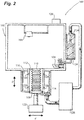
- Fig. 2 shows the recycled feedstock powder 114 returned to the dosing chamber 124 after evacuation from the build volume 112 through the powder evacuation cavity 116 for use in a subsequent build.
- a controller 128 is operatively connected to the build plate 108, the recoater 104, and the sintering laser 106 to control additive manufacture of a part 110 in the build volume 112.
- the controller 128 is operatively connected to the evacuation cavity 112 to automatically initiate powder removal, e.g., by opening the gating valves 120, from the build volume 112 after completing a build.
- the build plate 108 can provide the gating, e.g., wherein the gating valves 120 are simply ports connecting between the build volume 112 and the evacuation cavity 110 that are positioned so that the controller 128 can cause over-traveling of the build plate 108 below the ports to open the pathway from the build volume 112 to the evacuation cavity 110.
- a method of managing feedstock powder includes forming a part, e.g., part 110, from feedstock powder, e.g., feedstock powder 114, in a powder bed within a build volume, e.g., build volume 112.
- the method includes evacuating unsintered feedstock powder from the build volume after forming the part, wherein the unsintered feedstock powder flows into at least one evacuation cavity, e.g., evacuation cavity 116, at least partially surrounding the build volume.
- Evacuating unsintered feedstock powder can include opening at least one gating valve, e.g., gating valves 120, to place the at least one powder evacuation cavity in fluid communication with the build volume.
- the method can include dosing feedstock powder into the build volume from a dosing chamber, e.g., dosing chamber 124, wherein the dosing chamber and the at least one powder evacuation cavity are distinct and separate from one another.
- the method can include recycling feedstock powder from the at least one evacuation cavity to the dosing chamber through a closed loop recycling system, e.g., recycling system 126, for re-use of the unsintered feedstock powder. Recycling the feedstock powder can optionally include maintaining the closed loop recycling system under a controlled atmosphere.
- the method can include automatically controlling the at least one evacuation cavity to automatically initiate powder removal from the build volume after completing a build.
- a powder evacuation system as disclosed herein can remove feedstock powder from the build chamber by agitating the un-sintered powder feedstock using sub- to ultrasonic frequencies. Once the part build has completed, the oscillation transducer engages causing the static feedstock powder in the build volume to flow into one or more evacuation cavities that are located around the build plate platform in its most retracted state, i.e. its lowest position as oriented in Figs. 1 and 2 .
- the feedstock powder that has been evacuated in this manner can be collected and reprocessed in existing closed-loop powder circuits.
- Powder removal in conventional systems is a highly manual operation which is not standardized or quality controlled.
- post processing efforts are reduced and better controlled. Operators can be spared from exposure to free powder and the powder that has been evacuated from the build can be easily reintroduced into the feedstock supply without risking contamination.
Landscapes
- Engineering & Computer Science (AREA)
- Chemical & Material Sciences (AREA)
- Materials Engineering (AREA)
- Manufacturing & Machinery (AREA)
- Physics & Mathematics (AREA)
- Optics & Photonics (AREA)
- Mechanical Engineering (AREA)
- Life Sciences & Earth Sciences (AREA)
- Sustainable Development (AREA)
- Plasma & Fusion (AREA)
- Health & Medical Sciences (AREA)
- Environmental & Geological Engineering (AREA)
- Toxicology (AREA)
- Powder Metallurgy (AREA)
Abstract
Description
- The present disclosure relates to additive manufacturing, and more particularly to management of stock powder such as used in laser sintering for additive manufacturing.
- Powder evacuation and removal at the end of an additive manufacturing build is a highly manual operation in conventional additive manufacturing systems. This powder removal is non-standardized and the quality of the procedure is a function of the operator's diligence.
- The conventional techniques have been considered satisfactory for their intended purpose. However, there is an ever present need for improved feedstock powder management. This disclosure provides a solution for this need.
- An additive manufacturing system includes a build chamber housing a recoater and a sintering laser. A build plate is moveable within the build chamber to accommodate growth of a part formed by the recoater and the sintering laser. At least one powder evacuation cavity at least partially surrounds a build volume of the build chamber. The build volume of the build chamber is defined between the build plate and the recoater and is configured to hold a sintered part and unsintered powder during an additive manufacturing build in the build chamber.
- The at least one powder evacuation cavity can be selectively in fluid communication with the build volume through at least one gating valve. An oscillation transducer can be operatively connected to the build volume to vibrate the build volume sub- or ultrasonically to facilitate flow of powder from the build volume into the at least one powder evacuation cavity. The oscillation transducer can be configured to vibrate in a direction lateral to the build direction in the build volume. The at least one evacuation cavity can include a single evacuation cavity that surrounds the build volume peripherally.
- A dosing chamber can be operatively connected to supply feedstock powder to the build volume. The dosing chamber and the at least one powder evacuation cavity can be distinct and separate from one another. The at least one powder evacuation cavity and the dosing chamber can be operatively connected to one another by a recycling system configured to recycle used feedstock powder from the at least one powder evacuation cavity through a recycling process for re-use in the dosing chamber. The build chamber, the at least one evacuation cavity, the recycling system, and the dosing chamber can all be part of a controlled atmosphere closed loop.
- A controller can be operatively connected to the build plate, the recoater, and the sintering laser to control additive manufacture of a part in the build volume. The controller can be operatively connected to the at least one evacuation cavity to automatically initiate powder removal from the build volume after completing a build.
- A method of managing feedstock powder includes forming a part from feedstock powder in a powder bed within a build volume. The method includes evacuating unsintered feedstock powder from the build volume (e.g. after forming the part), wherein the unsintered feedstock powder flows into at least one evacuation cavity at least partially surrounding the build volume.
- Evacuating unsintered feedstock powder can include opening at least one gating valve to place the at least one powder evacuation cavity in fluid communication with the build volume. Evacuating unsintered feedstock powder can include vibrating the build volume sub- or ultrasonically to facilitate flow of powder from the build volume into the at least one powder evacuation cavity. Vibrating the build volume can include vibrating the build volume in a direction lateral to build direction in the build volume. The method can include dosing feedstock powder into the build volume from a dosing chamber, wherein the dosing chamber and the at least one powder evacuation cavity are distinct and separate from one another. The method can include recycling feedstock powder from the at least one evacuation cavity to the dosing chamber through a closed loop recycling system for re-use of the unsintered feedstock powder. Recycling the feedstock powder can include maintaining the closed loop recycling system under a controlled atmosphere. The method can include automatically controlling the at least one evacuation cavity to automatically initiate powder removal from the build volume after completing a build.
- These and other features of the systems and methods of the subject disclosure will become more readily apparent to those skilled in the art from the following detailed description of the preferred embodiments taken in conjunction with the drawings.
- So that those skilled in the art to which the subject disclosure appertains will readily understand how to make and use the devices and methods of the subject disclosure without undue experimentation, preferred embodiments thereof will be described in detail herein below with reference to certain figures, wherein:
-
Fig. 1 is a schematic side elevation view of an exemplary embodiment of an additive manufacturing system constructed in accordance with the present disclosure, showing a part being sintered from feedstock powder in the build volume; -
Fig. 2 is a schematic side elevation view of the system ofFig. 1 , showing feedstock powder evacuated through the evacuation cavity, recycled, and returned to the dosing chamber for use in another build; and -
Fig. 3 is a schematic plan view of the build volume and evacuation cavity ofFig. 1 . - Reference will now be made to the drawings wherein like reference numerals identify similar structural features or aspects of the subject disclosure. For purposes of explanation and illustration, and not limitation, a partial view of an exemplary embodiment of an additive manufacturing system in accordance with the disclosure is shown in
Fig. 1 and is designated generally byreference character 100. Other embodiments of systems in accordance with the disclosure, or aspects thereof, are provided inFigs. 2-3 , as will be described. The systems and methods described herein can be used to improve handling of feedstock powder, and particularly to improve automation of removal of feedstock powder from a build chamber after a build. - The
system 100 includes abuild chamber 102 housing arecoater 104 and a sinteringlaser 106. Abuild plate 108 is moveable within thebuild chamber 102 to accommodate growth of apart 110 formed by therecoater 104 and thesintering laser 106. At each stage during the build, the recoater 104 deposits a thin layer of feedstock powder in thebuild volume 112, and the sintering laser selectively sinters a portion of the thin layer offeedstock powder 114 onto thepart 110. As each new layer is sintered, thepart 110 grows in a build direction D, i.e., vertically as oriented inFigs. 1-2 , as theunsintered feedstock powder 114 accumulates around thepart 110 in thebuild volume 112. Thebuild volume 112 of thebuild chamber 102 is defined between, i.e. vertically between as oriented inFig. 1 , thebuild plate 108 and therecoater 104 and is configured to hold asintered part 110 andunsintered feedstock powder 114 during an additive manufacturing build in thebuild chamber 102. - At least one
powder evacuation cavity 116 at least partially surrounds thebuild volume 112 of thebuild chamber 102. As shown inFig. 3 , there is oneevacuation cavity 116 that completely surrounds thebuild volume 112 peripherally, however those skilled in the art will readily appreciate that any suitable number of evacuation cavities can be arranged at least partially around the periphery of thebuild volume 112 without departing from the scope of this disclosure. - The
powder evacuation cavity 116 is selectively in fluid communication with thebuild volume 112 through a plurality ofgating valves 120. Anoscillation transducer 122 is operatively connected to thebuild volume 112 to vibrate thebuild volume 112 sub- or ultrasonically to facilitate flow ofunsintered feedstock powder 114 from thebuild volume 112, through thegating valves 120 into the at least onepowder evacuation cavity 120. The oscillation transducer can be incorporated in the actuator for moving thebuild plate 108 in the build direction D, for example, and is configured to vibrate in a direction d that is lateral to the build direction D in thebuild volume 112. - A
dosing chamber 124 is operatively connected to supplyfeedstock powder 114 to thebuild volume 112. Thedosing chamber 124 and thepowder evacuation cavity 116 are distinct and separate chambers from one another. Thepowder evacuation cavity 112 and thedosing chamber 124 are operatively connected to one another by arecycling system 126 configured to recycle usedfeedstock powder 114 from thepowder evacuation cavity 116 through a recycling process, e.g., including filtering and straining, for re-use in thedosing chamber 124 for building asubsequent part 110. Thebuild chamber 102, theevacuation cavity 116, therecycling system 126, and thedosing chamber 124 can all be part of a controlled atmosphere closed loop so that thefeedstock powder 114 can be isolated from the ambient atmosphere.Fig. 1 shows thefeedstock powder 114 that is unsintered in thebuild chamber 112 during a build of thepart 110, andFig. 2 shows the recycledfeedstock powder 114 returned to thedosing chamber 124 after evacuation from thebuild volume 112 through thepowder evacuation cavity 116 for use in a subsequent build. - A
controller 128 is operatively connected to thebuild plate 108, therecoater 104, and the sinteringlaser 106 to control additive manufacture of apart 110 in thebuild volume 112. Thecontroller 128 is operatively connected to theevacuation cavity 112 to automatically initiate powder removal, e.g., by opening thegating valves 120, from thebuild volume 112 after completing a build. It is also contemplated that thebuild plate 108 can provide the gating, e.g., wherein thegating valves 120 are simply ports connecting between thebuild volume 112 and theevacuation cavity 110 that are positioned so that thecontroller 128 can cause over-traveling of thebuild plate 108 below the ports to open the pathway from thebuild volume 112 to theevacuation cavity 110. - A method of managing feedstock powder includes forming a part, e.g.,
part 110, from feedstock powder, e.g.,feedstock powder 114, in a powder bed within a build volume, e.g.,build volume 112. The method includes evacuating unsintered feedstock powder from the build volume after forming the part, wherein the unsintered feedstock powder flows into at least one evacuation cavity, e.g.,evacuation cavity 116, at least partially surrounding the build volume. - Evacuating unsintered feedstock powder can include opening at least one gating valve, e.g., gating
valves 120, to place the at least one powder evacuation cavity in fluid communication with the build volume. The method can include dosing feedstock powder into the build volume from a dosing chamber, e.g.,dosing chamber 124, wherein the dosing chamber and the at least one powder evacuation cavity are distinct and separate from one another. The method can include recycling feedstock powder from the at least one evacuation cavity to the dosing chamber through a closed loop recycling system, e.g.,recycling system 126, for re-use of the unsintered feedstock powder. Recycling the feedstock powder can optionally include maintaining the closed loop recycling system under a controlled atmosphere. The method can include automatically controlling the at least one evacuation cavity to automatically initiate powder removal from the build volume after completing a build. - A powder evacuation system as disclosed herein can remove feedstock powder from the build chamber by agitating the un-sintered powder feedstock using sub- to ultrasonic frequencies. Once the part build has completed, the oscillation transducer engages causing the static feedstock powder in the build volume to flow into one or more evacuation cavities that are located around the build plate platform in its most retracted state, i.e. its lowest position as oriented in
Figs. 1 and2 . The feedstock powder that has been evacuated in this manner can be collected and reprocessed in existing closed-loop powder circuits. - This process removes considerable lead time in post processing after a build. Powder removal in conventional systems is a highly manual operation which is not standardized or quality controlled. By having a reliable automated process for powder extraction, such as disclosed herein, post processing efforts are reduced and better controlled. Operators can be spared from exposure to free powder and the powder that has been evacuated from the build can be easily reintroduced into the feedstock supply without risking contamination.
- The methods and systems of the present disclosure, as described above and shown in the drawings, provide for feedstock powder management with superior properties including automatic removal of unsintered feedstock powder, and facilitated recycling of the feedstock powder. While the apparatus and methods of the subject disclosure have been shown and described with reference to preferred embodiments, those skilled in the art will readily appreciate that changes and/or modifications may be made thereto without departing from the scope of the invention as defined by the claims.
Claims (15)
- An additive manufacturing system comprising:a build chamber (102) housing a recoater (104) and a sintering laser (106);a build plate (108) that is moveable within the build chamber to accommodate growth of a part (110) formed by the recoater and the sintering laser; andat least one powder evacuation cavity (116) at least partially surrounding a build volume (112) of the build chamber, wherein the build volume of the build chamber is defined between the build plate and the recoater and is configured to hold a sintered part and unsintered powder (114) during an additive manufacturing build in the build chamber.
- The system as recited in claim 1, wherein the at least one powder evacuation cavity (116) is selectively in fluid communication with the build volume through at least one gating valve (120).
- The system as recited in claim 1 or 2, further comprising an oscillation transducer (122) operatively connected to the build volume to vibrate the build volume to facilitate flow of powder from the build volume into the at least one powder evacuation cavity.
- The system as recited in claim 3, wherein at least one of:the oscillation transducer is configured to vibrate in a direction lateral to build direction in the build volume; and/orthe oscillation transducer is configured to vibrate the build volume sub- or ultrasonically.
- The system as recited in any preceding claim, further comprising a dosing chamber (124) operatively connected to supply feedstock powder to the build volume, wherein the dosing chamber and the at least one powder evacuation cavity are distinct and separate from one another.
- The system as recited in claim 5, wherein the at least one powder evacuation cavity (116) and the dosing chamber (124) are operatively connected to one another by a recycling system configured to recycle used feedstock powder from the at least one powder evacuation cavity through a recycling process for re-use in the dosing chamber, and preferably wherein the build chamber, the at least one evacuation cavity, the recycling system, and the dosing chamber are all part of a controlled atmosphere closed loop.
- The system as recited in any preceding claim, wherein the at least one evacuation cavity (116) includes a single evacuation cavity that surrounds the build volume peripherally.
- The system as recited in any preceding claim, further comprising a controller (128) operatively connected to the build plate, the recoater, and the sintering laser to control additive manufacture of a part in the build volume, wherein the controller is operatively connected to the at least one evacuation cavity to automatically initiate powder removal from the build volume after completing a build.
- A method of managing feedstock powder comprising:forming a part from feedstock powder in a powder bed within a build volume (112);evacuating unsintered feedstock powder from the build volume, wherein the unsintered feedstock powder flows into at least one evacuation cavity at least partially surrounding the build volume.
- The method as recited in claim 9, wherein evacuating unsintered feedstock powder includes opening at least one gating valve (120) to place the at least one powder evacuation cavity (116) in fluid communication with the build volume, or wherein evacuating unsintered feedstock powder includes vibrating the build volume sub- or ultrasonically to facilitate flow of powder from the build volume into the at least one powder evacuation cavity.
- The method as recited in claim 10, wherein at least one of:vibrating includes vibrating in a direction lateral to build direction in the build volume; and/orvibrating includes vibrating the build volume sub- or ultrasonically.
- The method as recited in claim 9, 10 or 11, further comprising dosing feedstock powder into the build volume from a dosing chamber (124), wherein the dosing chamber and the at least one powder evacuation cavity are distinct and separate from one another.
- The method as recited in claim 12, further comprising recycling feedstock powder from the at least one evacuation cavity to the dosing chamber through a closed loop recycling system for re-use of the unsintered feedstock powder, and preferably wherein recycling the feedstock powder includes maintaining the closed loop recycling system under a controlled atmosphere.
- The method as recited in any of claims 9 to 13, further comprising automatically controlling the at least one evacuation cavity to automatically initiate powder removal from the build volume after completing a build.
- The method as recited in any of claims 9 to 14, wherein evacuating unsintered feedstock powder from the build volume is performed after forming the part
Applications Claiming Priority (1)
| Application Number | Priority Date | Filing Date | Title |
|---|---|---|---|
| US16/166,911 US11318676B2 (en) | 2018-10-22 | 2018-10-22 | Powder evacuation systems |
Publications (1)
| Publication Number | Publication Date |
|---|---|
| EP3643433A1 true EP3643433A1 (en) | 2020-04-29 |
Family
ID=68296305
Family Applications (1)
| Application Number | Title | Priority Date | Filing Date |
|---|---|---|---|
| EP19204411.3A Pending EP3643433A1 (en) | 2018-10-22 | 2019-10-21 | Powder evacuation systems |
Country Status (2)
| Country | Link |
|---|---|
| US (2) | US11318676B2 (en) |
| EP (1) | EP3643433A1 (en) |
Cited By (2)
| Publication number | Priority date | Publication date | Assignee | Title |
|---|---|---|---|---|
| CN112008979A (en) * | 2020-09-01 | 2020-12-01 | 淄博俊康文具有限公司 | Model dismounting device of SLA3D printer |
| US12042866B2 (en) | 2021-03-16 | 2024-07-23 | General Electric Company | Additive manufacturing apparatus and fluid flow mechanism |
Families Citing this family (2)
| Publication number | Priority date | Publication date | Assignee | Title |
|---|---|---|---|---|
| US12011879B2 (en) | 2020-12-21 | 2024-06-18 | Hamilton Sundstrand Corporation | Powder removal from a printed workpiece |
| CN113102777B (en) * | 2021-03-29 | 2022-12-06 | 西北工业大学 | Device and method for improving utilization rate of powder produced by additive manufacturing of powder feeding metal |
Citations (4)
| Publication number | Priority date | Publication date | Assignee | Title |
|---|---|---|---|---|
| EP1316408A1 (en) * | 2001-11-28 | 2003-06-04 | Concept Laser GmbH | Device for producing and/or processing objects made of powder particles |
| US20070001342A1 (en) * | 1999-08-06 | 2007-01-04 | Eos Gmbh Electro Optical Systems | Process and device for producing a three-dimensional object |
| US20160361874A1 (en) * | 2015-06-12 | 2016-12-15 | Ricoh Company, Ltd. | Apparatus for fabricating three-dimensional object |
| US20170144374A1 (en) * | 2015-11-20 | 2017-05-25 | Ricoh Company, Ltd. | Three-dimensional shaping apparatus and three-dimensional shaping system |
Family Cites Families (9)
| Publication number | Priority date | Publication date | Assignee | Title |
|---|---|---|---|---|
| US20040084814A1 (en) * | 2002-10-31 | 2004-05-06 | Boyd Melissa D. | Powder removal system for three-dimensional object fabricator |
| US20060214335A1 (en) * | 2005-03-09 | 2006-09-28 | 3D Systems, Inc. | Laser sintering powder recycle system |
| US10315408B2 (en) * | 2015-04-28 | 2019-06-11 | General Electric Company | Additive manufacturing apparatus and method |
| FR3039436B1 (en) | 2015-07-30 | 2021-09-24 | Michelin & Cie | DEVICE FOR DRY CLEANING OF AN ADDITIVE MANUFACTURING TRAY |
| US10913206B2 (en) | 2015-08-03 | 2021-02-09 | Delavan, Inc | Systems and methods for post additive manufacturing processing |
| US10207454B2 (en) * | 2015-12-10 | 2019-02-19 | Velo3D, Inc. | Systems for three-dimensional printing |
| GB201600629D0 (en) | 2016-01-13 | 2016-02-24 | Renishaw Plc | Powder bed fusion apparatus and methods |
| US10583606B2 (en) * | 2016-02-11 | 2020-03-10 | General Electric Company | Method and supports with powder removal ports for additive manufacturing |
| IT201600113040A1 (en) * | 2016-11-09 | 2018-05-09 | 3D4Mec Srl | 3D LASER PRINTER |
-
2018
- 2018-10-22 US US16/166,911 patent/US11318676B2/en active Active
-
2019
- 2019-10-21 EP EP19204411.3A patent/EP3643433A1/en active Pending
-
2022
- 2022-04-26 US US17/729,649 patent/US20220250325A1/en not_active Abandoned
Patent Citations (4)
| Publication number | Priority date | Publication date | Assignee | Title |
|---|---|---|---|---|
| US20070001342A1 (en) * | 1999-08-06 | 2007-01-04 | Eos Gmbh Electro Optical Systems | Process and device for producing a three-dimensional object |
| EP1316408A1 (en) * | 2001-11-28 | 2003-06-04 | Concept Laser GmbH | Device for producing and/or processing objects made of powder particles |
| US20160361874A1 (en) * | 2015-06-12 | 2016-12-15 | Ricoh Company, Ltd. | Apparatus for fabricating three-dimensional object |
| US20170144374A1 (en) * | 2015-11-20 | 2017-05-25 | Ricoh Company, Ltd. | Three-dimensional shaping apparatus and three-dimensional shaping system |
Cited By (3)
| Publication number | Priority date | Publication date | Assignee | Title |
|---|---|---|---|---|
| CN112008979A (en) * | 2020-09-01 | 2020-12-01 | 淄博俊康文具有限公司 | Model dismounting device of SLA3D printer |
| CN112008979B (en) * | 2020-09-01 | 2021-04-30 | 武汉山尚一品艺术创意有限公司 | Model dismounting device of SLA3D printer |
| US12042866B2 (en) | 2021-03-16 | 2024-07-23 | General Electric Company | Additive manufacturing apparatus and fluid flow mechanism |
Also Published As
| Publication number | Publication date |
|---|---|
| US20220250325A1 (en) | 2022-08-11 |
| US20200122396A1 (en) | 2020-04-23 |
| US11318676B2 (en) | 2022-05-03 |
Similar Documents
| Publication | Publication Date | Title |
|---|---|---|
| US20220250325A1 (en) | Powder evacuation systems | |
| EP2414151B1 (en) | Transport container | |
| CN109070456B (en) | Additive manufacturing machine comprising an extraction system and additive manufacturing method using such a machine | |
| US10046393B2 (en) | Three dimensional printer | |
| CN107052336B (en) | Method for additive manufacturing and support with powder removal ports | |
| DE69816666T2 (en) | Method and device for producing molded parts, in particular optical lenses | |
| DE69804899T2 (en) | Process for the rapid robotized treatment of small form elements | |
| DE69226353T2 (en) | DEVICE FOR VACUUM POURING | |
| US10029308B2 (en) | Three dimensional printer | |
| DE102009038241A1 (en) | A method of manufacturing a three-dimensionally shaped article, an apparatus for producing the same, and a three-dimensionally shaped article | |
| EP2522446A1 (en) | Device for subsequent manufacturing of moulded bodies by layered construction using a material powder | |
| US20170225198A1 (en) | Method and apparatus for treatment of contaminated metal powder | |
| DE102015110937B4 (en) | Suction device and suction method | |
| EP2897791B1 (en) | Process for producing wind power plant rotor blades and for producing a mould core therefor | |
| DE102016109212A1 (en) | Powdering of a rapid prototyping component | |
| US10926329B2 (en) | Methods and apparatuses to grow compression chambers in powder based additive manufacturing to relieve powder loading on grown part | |
| US9919359B2 (en) | Method of and a device for the compaction of a powder into a cutting insert green body | |
| CN105980119B (en) | Method for casting ceramic parts | |
| WO2018182791A1 (en) | Three dimensional printing system that automatically removes particles from build plane | |
| DE112019006420T5 (en) | GAS PHASE SEPARATION DEVICE | |
| EP3643472B1 (en) | Manufacture of injection moulded parts in unique moulds | |
| EP4068343A1 (en) | Device for transporting semiconductor wafers | |
| JP6292835B2 (en) | Optical element manufacturing apparatus and optical element manufacturing method | |
| CN112351956B (en) | Lens forming device and filter device | |
| US20250319503A1 (en) | Automated de-powdering of additive manufacturing build |
Legal Events
| Date | Code | Title | Description |
|---|---|---|---|
| PUAI | Public reference made under article 153(3) epc to a published international application that has entered the european phase |
Free format text: ORIGINAL CODE: 0009012 |
|
| STAA | Information on the status of an ep patent application or granted ep patent |
Free format text: STATUS: THE APPLICATION HAS BEEN PUBLISHED |
|
| AK | Designated contracting states |
Kind code of ref document: A1 Designated state(s): AL AT BE BG CH CY CZ DE DK EE ES FI FR GB GR HR HU IE IS IT LI LT LU LV MC MK MT NL NO PL PT RO RS SE SI SK SM TR |
|
| AX | Request for extension of the european patent |
Extension state: BA ME |
|
| STAA | Information on the status of an ep patent application or granted ep patent |
Free format text: STATUS: REQUEST FOR EXAMINATION WAS MADE |
|
| 17P | Request for examination filed |
Effective date: 20201029 |
|
| RBV | Designated contracting states (corrected) |
Designated state(s): AL AT BE BG CH CY CZ DE DK EE ES FI FR GB GR HR HU IE IS IT LI LT LU LV MC MK MT NL NO PL PT RO RS SE SI SK SM TR |
|
| STAA | Information on the status of an ep patent application or granted ep patent |
Free format text: STATUS: EXAMINATION IS IN PROGRESS |
|
| 17Q | First examination report despatched |
Effective date: 20230606 |