EP3643424A1 - Fastening tool - Google Patents
Fastening tool Download PDFInfo
- Publication number
- EP3643424A1 EP3643424A1 EP18821549.5A EP18821549A EP3643424A1 EP 3643424 A1 EP3643424 A1 EP 3643424A1 EP 18821549 A EP18821549 A EP 18821549A EP 3643424 A1 EP3643424 A1 EP 3643424A1
- Authority
- EP
- European Patent Office
- Prior art keywords
- housing
- fastener
- fastening tool
- pin
- end portion
- Prior art date
- Legal status (The legal status is an assumption and is not a legal conclusion. Google has not performed a legal analysis and makes no representation as to the accuracy of the status listed.)
- Granted
Links
Images




Classifications
-
- B—PERFORMING OPERATIONS; TRANSPORTING
- B21—MECHANICAL METAL-WORKING WITHOUT ESSENTIALLY REMOVING MATERIAL; PUNCHING METAL
- B21J—FORGING; HAMMERING; PRESSING METAL; RIVETING; FORGE FURNACES
- B21J15/00—Riveting
- B21J15/10—Riveting machines
- B21J15/16—Drives for riveting machines; Transmission means therefor
- B21J15/26—Drives for riveting machines; Transmission means therefor operated by rotary drive, e.g. by electric motor
-
- B—PERFORMING OPERATIONS; TRANSPORTING
- B21—MECHANICAL METAL-WORKING WITHOUT ESSENTIALLY REMOVING MATERIAL; PUNCHING METAL
- B21J—FORGING; HAMMERING; PRESSING METAL; RIVETING; FORGE FURNACES
- B21J15/00—Riveting
- B21J15/02—Riveting procedures
- B21J15/04—Riveting hollow rivets mechanically
- B21J15/043—Riveting hollow rivets mechanically by pulling a mandrel
-
- B—PERFORMING OPERATIONS; TRANSPORTING
- B21—MECHANICAL METAL-WORKING WITHOUT ESSENTIALLY REMOVING MATERIAL; PUNCHING METAL
- B21J—FORGING; HAMMERING; PRESSING METAL; RIVETING; FORGE FURNACES
- B21J15/00—Riveting
- B21J15/10—Riveting machines
- B21J15/30—Particular elements, e.g. supports; Suspension equipment specially adapted for portable riveters
- B21J15/32—Devices for inserting or holding rivets in position with or without feeding arrangements
- B21J15/326—Broken-off mandrel collection
-
- B—PERFORMING OPERATIONS; TRANSPORTING
- B21—MECHANICAL METAL-WORKING WITHOUT ESSENTIALLY REMOVING MATERIAL; PUNCHING METAL
- B21J—FORGING; HAMMERING; PRESSING METAL; RIVETING; FORGE FURNACES
- B21J15/00—Riveting
- B21J15/10—Riveting machines
- B21J15/105—Portable riveters
Definitions
- the present invention relates to a fastening tool which fastens a workpiece via a fastener.
- a fastening tool which fastens a plurality of workpieces via a fastener having a pin and a cylindrical part.
- a so-called blind rivet and a so-called multi-piece swage type fastener may be used.
- the blind rivet is a fastener of a type having a pin and a cylindrical part (also referred to as a rivet body or a sleeve) which are formed integrally with each other.
- the multi-piece swage type fastener is a fastener of a type having a pin and a cylindrical part (also referred to as a collar) which are formed separately from each other.
- Japanese laid-open patent publication No. 2013-173148 discloses a fastening tool for a blind rivet.
- This fastening tool is configured to swage a cylindrical part by a feed-screw mechanism pulling a pin gripped by a jaw out of the cylindrical part along a specified axis.
- an electric motor for driving the feed-screw mechanism is disposed in a position displaced from a region between a handle gripping position and the feed-screw mechanism in a circumferential direction around the axis. More specifically, when viewed from the rear, the feed-screw mechanism is aligned, in the up-down direction, with a center line of the handle, while the electric motor is disposed in a position displaced to the right from the center line. Therefore, operability may be lowered due to the weight imbalance in the left-right direction.
- a fastening tool which is configured to fasten a workpiece via a fastener having a pin and a cylindrical part.
- the fastening tool includes a housing, a fastener-abutment part, a pin-gripping part, a motor, a driving mechanism and a handle.
- the housing extends in a front-rear direction of the fastening tool along a specified driving axis.
- the fastener-abutment part is held by a front end portion of the housing so as to be capable of abutting on the cylindrical part of the fastener.
- the pin-gripping part is held to be movable in the front-rear direction along the driving axis relative to the fastener-abutment part and configured to grip a portion of the pin of the fastener.
- the motor is housed in the housing. Further, the motor includes a motor body and a motor shaft.
- the motor body includes a stator and a rotor.
- the motor shaft extends from the rotor.
- the driving mechanism is at least partially housed in the housing.
- the driving mechanism is configured to be driven by power of the motor and configured to move the pin-gripping part rearward along the driving axis relative to the fastener-abutment part to pull the pin gripped by the pin-gripping part and deform the cylindrical part abutting on the fastener-abutment part, thereby fastening the workpiece via the fastener.
- the handle protrudes downward from the housing in an up-down direction, which is orthogonal to the front-rear direction. Further, the handle has a trigger which is provided in an upper end portion of the handle and configured to be depressed by a user.
- the driving mechanism includes a rotary member and a movable member.
- the rotary member is supported by the housing so as to be rotatable around the driving axis while its movement in the front-rear direction is restricted.
- the rotary member is configured to be rotationally driven by the power of the motor.
- the movable member is connected to the pin-gripping part. Further, the movable member is configured to be engaged with the rotary member so as to be movable in the front-rear direction along the driving axis while its rotation around the driving axis is restricted, thereby linearly moving in the front-rear direction when the rotary member is rotationally driven.
- a rotation axis of the motor shaft extends in parallel to the driving axis on a lower side of the driving axis.
- a virtual plane including the driving axis and the rotation axis passes a center of the handle in a left-right direction, which is orthogonal to the front-rear direction and the up-down direction.
- the trigger is disposed between the rotary member and the motor body in the front-rear direction.
- the driving mechanism may move the pin-gripping part in the front-rear direction relative to the fastener-abutment part.
- the driving mechanism includes the rotary member configured to be rotationally driven by the power of the motor and the movable member configured to linearly move in the front-rear direction when the rotary member is rotationally driven.
- the arrangement relation among the motor, the driving mechanism and the handle is set such that the virtual plane including the driving axis and the rotation axis of the motor shaft which are arranged in parallel in the up-down direction passes the center of the handle in the left-right direction.
- the rotary member, the movable member, the motor and the handle are arranged in left-right symmetry (in plane symmetry relative to the above-described virtual plane).
- an excellent weight balance can be realized in the left-right direction, so that operability of the fastening tool can be improved.
- the motor since the motor is not arranged coaxially with the driving mechanism, the housing can be reduced in size in the front-rear direction.
- the trigger since the trigger is disposed between the rotary member and the motor body which are relatively heavy, an excellent weight balance can also be realized in the front-rear direction, so that operability of the fastening tool can be improved.
- Examples of the fastener which can be used for the fastening tool of the present aspect may include a so-called blind rivet and a multi-piece swage type fastener.
- the pin and the cylindrical part are integrally formed with each other.
- a flange may be integrally formed on one end of the cylindrical part.
- a shaft part of the pin may extend through the cylindrical part.
- the shaft part of the pin may protrude long from one end of the cylindrical part on which the flange is formed and a head may protrude adjacent to the other end of the cylindrical part.
- the blind rivet is a fastener of a type which can clamp a workpiece between one end portion (flange) of the cylindrical part and the other end portion of the cylindrical part which is deformed to be enlarged in diameter by the pin being pulled in an axial direction.
- the pin and the cylindrical part (also referred to as a collar) through which the pin is inserted are originally formed separately from each other.
- the multi-piece swage type fastener is a fastener of a type which can clamp a workpiece between a head of the pin and the cylindrical part swaged to a shaft part of the pin.
- the multi-piece swage type fastener includes a fastener of the type in which the pintail is torn off like in the blind rivet, and a fastener of the type in which the shaft part is retained as it is.
- the fastener of either type the pin is moved relative to the cylindrical part by a fastening mechanism so that a workpiece is fastened with the fastener.
- the housing may also be referred to as a tool body.
- the housing may be formed by connecting a plurality of parts. Further, the housing may have a one-layer structure or a two-layer structure.
- the motor may be a direct current (DC) motor or an alternate current (AC) motor.
- DC direct current
- AC alternate current
- the presence or absence of a brush is not particularly limited. However, a brushless DC motor may be preferably adopted since it is compact and has high output.
- the structure of the fastener-abutment part is not particularly limited, as long as the fastener-abutment part is capable of abutting on the cylindrical part of the fastener.
- the fastener-abutment part may be configured to abut on and press the flange of the cylindrical part (rivet body or sleeve).
- the fastener-abutment part may be configured to be engaged with the cylindrical part (collar) to thereby deform the cylindrical part by a swaging force.
- any known structure can be employed.
- the fastener-abutment part may be typically configured as a cylindrical body.
- the fastener-abutment part may be held by a housing by being connected to the housing directly or via a different member. It is noted that the fastener-abutment part may be configured to be detachable from the housing.
- the structure of the pin-gripping part is not particularly limited, as long as the pin-gripping part is held to be movable in the front-rear direction along the driving axis relative to the fastener-abutment part and configured to grip a portion of the pin.
- any known structure can be employed which includes a jaw having a plurality of claws configured to grip a portion of a pin (specifically, a shaft part of the pin) and a jaw-holding part (also referred to as a jaw case).
- the pin-gripping part may be disposed coaxially with the cylindrical fastener-abutment part within the fastener-abutment part. It is noted that the pin-gripping part may be configured to be detachable from the housing.
- a feed-screw mechanism or a ball-screw mechanism may be suitably adopted. Both the feed-screw mechanism and the ball-screw mechanism are capable of converting rotation into linear motion.
- a female thread part formed in an inner peripheral surface of the cylindrical rotary member and a male thread part formed in an outer peripheral surface of the movable member inserted through the rotary member are engaged (threadedly engaged) directly with each other.
- a spiral track is defined between the inner peripheral surface of the cylindrical rotary member and the outer peripheral surface of the movable member inserted through the rotary member.
- the rotary member and the movable member are engaged with each other via a number of balls which are rollably disposed within the spiral track.
- the rotary member may be held by the housing via a bearing.
- the movable member may be connected to the pin-gripping part directly or via a different member (that is, indirectly).
- the handle may typically have an elongate shape and include a rod-like grip part to be held by a user.
- the handle that "protrudes downward from the housing" here may include not only the handle protruding in a downward direction orthogonal to the driving axis, but also the handle protruding in a generally downward direction crossing the driving axis.
- the trigger may be typically provided as an operation member for starting the motor.
- the rotary member and the motor body may be spaced apart from each other in the front-rear direction.
- the motor body may not be disposed below the rotary member. Therefore, the trigger can be disposed closer to the driving axis above, so that operability of the fastening tool can be further improved.
- the rotary member and the motor may be arranged to partially overlap with each other when viewed from the rear.
- the housing can be reduced in size in the up-down direction, and the trigger can be further reliably disposed closer to the driving axis.
- the "rotary member" used herein may refer to an entirety of the rotary member including the driven gear.
- the rotary member may have a driven gear formed on its outer periphery.
- the driving mechanism may include an intermediate shaft.
- the intermediate shaft may be configured to be rotationally driven along with rotation of the motor shaft.
- the intermediate shaft may have a driving gear which is engaged with the driven gear.
- the intermediate shaft may be arranged coaxially with the motor shaft.
- the housing can be reduced in size in the up-down direction compared with a case in which the intermediate shaft is arranged in parallel to the motor shaft.
- the driving mechanism may be configured to fasten the workpiece via the fastener and break the pin at a small-diameter part for breakage.
- the fastening tool may further include a pintail passage and a collection container for a pintail.
- the pintail passage may extend in the front-rear direction along the driving axis and be configured to allow passage of the pintail which is separated by breakage of the pin.
- the collection container may be removably attached to a rear end portion of the housing and have an internal space which communicates with a rear end of the pintail passage.
- the pintail passage since the pintail passage extends linearly along the driving axis, the pintail can smoothly pass the passage. Further, since the collection container can be attached to and detached from the rear end portion of the housing, attaching/detaching operation may be easier, compared with a case of the collection container to be disposed on an intermediate portion of the housing.
- the collection container may be formed such that the driving axis and the rotation axis of the motor shaft are located within a region occupied by the collection container when viewed from the rear.
- the volume of the collection container can be secured within a reasonable range corresponding to a rear end portion of the housing.
- the movable member may be configured as a hollow member having the pintail passage.
- the fastening tool may further include a dustproof member.
- the dustproof member may be held by the rear end portion of the housing and held in contact with an outer peripheral surface of a rear end portion of the movable member.
- the dustproof member may be disposed such that the movable member moves in the front-rear direction with the outer peripheral surface in sliding contact with the dustproof member, thereby preventing dust from entering an area forward of the dustproof member.
- Metal powder generated by breakage of the pin may stick to the pintail and be carried into the collection container and easily accumulated therein. This metal powder may stick to the outer peripheral surface of the rear end portion of the movable member and enter the inside of the housing.
- the dustproof member which is arranged such that the movable member moves in the front-rear direction with the outer peripheral surface in sliding contact with the dustproof member can prevent various foreign matters (dust) such as metal powder and sand from entering an area forward of the dustproof member.
- dust foreign matters
- the material of the dustproof member is not particularly limited, but, for example, felt, rubber, nonwoven fabric, paper, sponge and the like may be employed.
- the shape of the dustproof member is not particularly limited, but, for example, an annular member which surrounds the outer peripheral surface of the movable member, a brush-like member which surrounds the outer peripheral surface of the movable member and the like may be employed.
- the fastening tool may further include an illumination device and a trigger-protection part.
- the illumination device may be disposed in a lower end portion of the housing and configured to irradiate light to a peripheral region of a front end portion of the fastener-abutment part.
- the trigger-protection part may extend from the lower end portion of the housing to a front end portion of the handle, while securing a space for a user's finger in front of the trigger.
- the trigger-protection part may have a passage for wiring for the illumination device inside.
- illumination may facilitate checking the states of the fastener and the workpiece. Further, the trigger-protection part can realize both a function of preventing the trigger from being accidentally depressed and a function of providing a wiring passage for the illumination device.
- the housing may include a rotary-member-holding part that supports the rotary member.
- the fastening tool may further include an elastic member that is disposed behind the rotary member and between the rotary member and the rotary-member-holding part.
- a strong force may act to relatively move the rotary member rearward on impact. Accordingly, rearward impact may be applied to a portion of the rotary-member-holding part which is disposed behind the rotary member.
- the elastic member may be disposed between the rotary member and the rotary-member-holding part of the housing. Therefore, the possibility of damage to the rotary-member-holding part can be effectively reduced by the elastic member cushioning the impact. Thus, durability of the housing including the rotary-member-holding part can be enhanced.
- the housing may include a rotary-member-holding part that supports the rotary member.
- the fastening tool may further include an intervening member and a position-detecting mechanism.
- the intervening member may be disposed between the rotary member and the rotary-member-holding part in the front-rear direction.
- the position-detecting mechanism may be configured to detect that the pin-gripping part is located in a specified reference position.
- the driving mechanism may be configured to move the pin-gripping part forward along the driving axis relative to the fastener-abutment part to be placed in a specified initial position based on a detection result of the detection device after the workpiece is fastened.
- the intervening member may be configured to abut on an abutment part of the movable member when the pin-gripping part connected to the movable member is moved forward beyond the initial position, thereby preventing the movable member and the pin-gripping part from further moving forward.
- the pin-gripping part in a case where the pin-gripping part is moved forward beyond the initial position, the pin-gripping part may abut on the intervening member and may be prevented from further moving forward.
- the reference position and the initial position may be the same or different.
- the intervening member can prevent movement of the movable member and the pin-gripping part even if the pin-gripping part is moved beyond the initial position, for example, due to malfunction of the position-detecting mechanism. Therefore, the possibility of damage to other parts can be reduced which may be caused by further forward movement of the movable member and the pin-gripping part beyond the limit.
- a fastening tool 1 which is capable of fastening a workpiece by using a fastener.
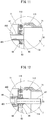
- a fastener 8 is described as an example of a fastener which can be used in the fastening tool 1, with reference to FIG. 1 .
- the fastener 8 is a known fastener of a type which may be referred to as a blind rivet (also referred to as a blind fastener).
- the fastener 8 includes a pin 81 and a body 85 which are integrally formed with each other.
- the body 85 is a cylindrical member which includes a cylindrical sleeve 851 and a flange 853 protruding radially outward from one end of the sleeve 851.
- the pin 81 is a rod-like member extending through the body 85 and protruding from both ends of the body 85.
- the pin 81 includes a shaft part 811 and a head 815 formed on one end portion of the shaft part 811.
- the head 815 has a larger diameter than the inner diameter of the sleeve 851 and is arranged to protrude from the other end of the sleeve 851 on the side opposite to the flange 853.
- the shaft part 811 extends through the body 85 and protrudes in an axial direction from the end of the body 85 on the side of the flange 853.
- a portion of the shaft part 811 which is disposed within the sleeve 851 has a small-diameter part 812 for breakage.
- the small-diameter part 812 has a less strength than other portions of the shaft part 811.
- the small-diameter part 812 is configured to be first broken when the pin 81 is pulled in the axial direction.
- a portion of the shaft part 811 on the side opposite to the head 815 across the small-diameter part 812 is referred to as a pintail 813.
- the pintail 813 is a portion to be separated from the pin 81 (the fastener 8) when the shaft part 811 is broken.
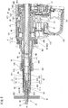
- the fastening tool 1 is now described. First, the general structure of the fastening tool 1 is described with reference to FIG. 2 .
- an outer shell of the fastening tool 1 is mainly formed by an outer housing 11, a handle 15 and a nose part 6 which is held via a nose-holding member 14.
- the outer housing 11 has a generally rectangular box-like shape and extends along a specified driving axis A1.
- the nose part 6 is held by one end portion of the outer housing 11 in a longitudinal direction via the nose-holding member 14 so as to extend along the driving axis A1.
- a collection container 7 is removably mounted to the other end portion of the outer housing 11.
- the collection container 7 is configured to store the pintail 813 (see FIG. 1 ) separated in a fastening process.
- the handle 15 protrudes in a direction crossing (in the present embodiment, a direction generally orthogonal to) the driving axis A1 from a central portion of the outer housing 11 in the longitudinal direction.
- an extending direction of the driving axis A1 (also referred to as a longitudinal direction of the outer housing 11) is defined as a front-rear direction of the fastening tool 1.
- the side on which the nose part 6 is disposed is defined as a front side and the side on which the collection container 7 is removably mounted is defined as a rear side.
- a direction which is orthogonal to the driving axis A1 and which corresponds to the extending direction of the handle 15 is defined as an up-down direction.
- the side on which the outer housing 11 is disposed is defined as an upper side and a protruding end (free end) side of the handle 15 is defined as a lower side.
- a direction orthogonal to the front-rear direction and the up-down direction is defined as a left-right direction.
- the outer housing 11 mainly houses a motor 2, a driving mechanism 4 which is configured to be driven by power of the motor 2 and a transmitting mechanism 3 which is configured to transmit power of the motor 2 to the driving mechanism 4.
- a portion (specifically, a nut 41 of a ball-screw mechanism 40) of the driving mechanism 4 is housed in an inner housing 13.
- the inner housing 13 is fixedly held by the outer housing 11. From this point of view, the outer housing 11 and the inner housing 13 can be considered as one piece in the form of a housing 10.
- the outer housing 11 is integrally formed of plastic with the handle 15, and the inner housing 13 is formed of metal (specifically, aluminum).
- the handle 15 is configured to be held by a user.
- a trigger 151 is provided in an upper end portion (a base end portion connected to the outer housing 11) of the handle 15.
- the trigger 151 is configured to be depressed (pulled) by a user.
- a battery mounting part 158 is provided in a lower end portion of the handle 15.
- the battery mounting part 158 is configured such that a battery 159 is removably mounted thereto.
- the battery 159 is a rechargeable power source for supplying electric power to each part of the fastening tool 1 and the motor 2.
- the structures of the battery mounting part 158 and the battery 159 are well known and therefore not described here.
- the fastening tool 1 of the present embodiment is configured to fasten a workpiece via the fastener 8.
- the fastener 8 (see FIG. 1 ) is gripped by a jaw 65 to be described later, in a state in which a portion of the pintail 813 is inserted into a front end portion of the nose part 6 of the fastening tool 1 and the body 85 and the head 815 protrude from a front end of the nose part 6 (see FIG. 5 ).
- the sleeve 851 is inserted through mounting holes formed in workpieces W to be fastened, up to a position where the flange 853 abuts on one side of the workpieces W.
- the driving mechanism 4 is driven via the motor 2.
- the motor 2 is described. As shown in FIG. 3 , the motor 2 is housed in a lower portion of a rear end portion of the outer housing 11.
- a compact and high-output brushless DC motor is employed as the motor 2.
- the motor 2 includes a motor body 20, which includes a stator 21 and a rotor 23, and a motor shaft 25, which extends from the rotor 23 and rotates together with the rotor 23.
- the motor 2 is arranged such that a rotation axis A2 of the motor shaft 25 extends in parallel to the driving axis A1 (that is, in the front-rear direction) below the driving axis A1. Further, in the present embodiment, the entirety of the motor 2 is disposed below the driving axis A1.
- the motor shaft 25 is rotatably supported by a bearing 251 which is fixed to a rear end portion of a speed-reducer housing 30 to be described later and a bearing 253 which is fixed to a rear end portion of the outer housing 11. A front end portion of the motor shaft 25 protrudes into the speed-reducer housing 30. A fan 27 for cooling the motor 2 is fixed to a rear end portion of the motor shaft 25.
- the transmitting mechanism 3 mainly includes a planetary-gear reducer 31, an intermediate shaft 33 and a nut-driving gear 35, which are now described in this order.
- the planetary-gear reducer 31 is disposed on the downstream side of the motor 2 on a power transmission path from the motor 2 to the driving mechanism 4 (specifically, a ball-screw mechanism 40).
- the planetary-gear reducer 31 is configured to increase torque of the motor 2 and transmit it to the intermediate shaft 33.
- the planetary-gear reducer 31 mainly includes two sets of planetary-gear mechanisms and the speed-reducer housing 30 which houses the planetary-gear mechanisms. It is noted that the speed-reducer housing 30 is formed of plastic and fixedly held by the outer housing 11 in front of the motor 2. The structure of the planetary-gear mechanism itself is well known and therefore not described in further detail here.
- the motor shaft 25 is an input shaft for inputting rotating power into the planetary-gear reducer 31.
- a sun gear 311 of a first (upstream) planetary-gear mechanism of the planetary-gear reducer 31 is fixed to a front end portion (the portion which protrudes into the speed-reducer housing 30) of the motor shaft 25.
- a carrier 313 of a second (downstream) planetary-gear mechanism is a final output shaft of the planetary-gear reducer 31.
- the intermediate shaft 33 is configured to rotate together with the carrier 313. Specifically, the intermediate shaft 33 is arranged coaxially with the motor shaft 25 and its rear end portion is connected to the carrier 313. Front and rear end portions of the intermediate shaft 33 are rotatably supported by a bearing 331 which is fixed to a lower front end portion of the inner housing 13 and a bearing 333 which is fixed to a front end portion of the speed-reducer housing 30, respectively.
- the nut-driving gear 35 is fixed onto an outer periphery of a front end portion of the intermediate shaft 33.
- the nut-driving gear 35 is engaged with a driven gear 411 formed on an outer periphery of the nut 41, which will be described later, and transmits the rotating power of the intermediate shaft 33 to the nut 41.
- the nut-driving gear 35 and the driven gear 411 are configured as a speed-reducing-gear mechanism. Further, in the present embodiment, the reduction ratio of the transmitting mechanism 3 as a whole is set to 3 or less.
- the driving mechanism 4 is now described.
- the driving mechanism 4 mainly includes the ball-screw mechanism 40 which is housed in an upper portion of the outer housing 11.
- the structures of the ball-screw mechanism 40 and its peripheries are now described.
- the ball-screw mechanism 40 is described below.
- the ball-screw mechanism 40 mainly includes the nut 41 and a screw shaft 46.
- the ball-screw mechanism 40 is configured to convert rotation of the nut 41 into linear motion of the screw shaft 46 and to linearly move the jaw assembly 63, which will be described later (see FIG. 5 ).
- the nut 41 is supported by the inner housing 13 so as to be rotatable around the driving axis A1 while its movement in the front-rear direction is restricted.
- the nut 41 is cylindrically shaped and has the driven gear 411 integrally formed on its outer periphery.
- a pair of radial bearings 412, 413 are fitted onto the nut 41 on the front and rear sides of the driven gear 411.
- the nut 41 is supported via the radial bearings 412, 413 so as to be rotatable around the driving axis A1 relative to the inner housing 13.
- the inner housing 13 includes a front housing 131 and a rear housing 133.
- the front housing 131 holds a front portion (specifically, a portion extending forward from the driven gear 411) of the nut 41.
- the rear housing 133 holds a rear portion (specifically, the driven gear 411 and a portion extending rearward from the driven gear 411) of the nut 41.
- the front housing 131 is configured to cover a region in front of the nut 41 and an outer periphery of the front portion of the nut 41.
- the rear housing 133 is configured to cover a region behind the nut 41 and an outer peripheries of the driven gear 411 and the rear portion of the nut 41.
- the inner housing 13 having the two parts disposed on the front and rear sides of the nut 41, movement of the nut 41 in the front-rear direction can be more reliably restricted during operation of the driving mechanism 4.
- the front housing 131 and the rear housing 133 are connected and fixed in the front-rear direction by screws (not shown) to be integrated as one unit.
- the radial bearings 412, 413 are fixed to the insides of the front housing 131 and the rear housing 133, respectively.
- the portions of the front housing 131 and the rear housing 133 which cover the outer periphery of the nut 41 have a rectangular external shape as a whole.
- An opening 134 is formed in a portion corresponding to the driven gear 411 in each of four upper, lower, left and right sides of the rear housing 133.
- the diameter of the driven gear 411 is set such that the outer periphery of the driven gear 411 is placed substantially flush with the outer surface of the inner housing 13 through the opening 134 formed in the upper side of the rear housing 133.
- the outer periphery of the driven gear 411 does not protrude upward from the upper surface of the inner housing 13.
- the driven gear 411 engages with the nut-driving gear 35.
- the driven gear 411 is rotated by the nut-driving gear 35, which causes the nut 41 to rotate around the driving axis A1.
- the screw shaft 46 is engaged with the nut 41 so as to be movable along the driving axis A1 in the front-rear direction while its rotation around the driving axis A1 is restricted.
- the screw shaft 46 is formed as an elongate member.
- the screw shaft 46 is inserted through the nut 41 and extends along the driving axis A1.
- a spiral track is defined by a spiral groove formed in an inner peripheral surface of the nut 41 and a spiral groove formed in an outer peripheral surface of the screw shaft 46.
- a number of balls (not shown) are rollably disposed within the spiral track.
- the screw shaft 46 is engaged with the nut 41 via these balls.
- the screw shaft 46 linearly moves along the driving axis A1 in the front-rear direction when the nut 41 is rotationally driven.
- a central portion of a roller holding part 463 is fixed to a rear end portion of the screw shaft 46.
- the roller holding part 463 has arms protruding orthogonally to the screw shaft 46 leftward and rightward from the central portion.
- Rollers 464 are rotatably held on right and left end portions of the arms, respectively.
- Roller guides 111 extending in the front-rear direction are fixed to right and left inner walls of the outer housing 11, respectively, corresponding to the pair of right and left rollers 464.
- each of the rollers 464 is restricted from moving upward and downward by the roller guide 111. Therefore, the roller 464 disposed within the roller guide 111 can roll along the roller guide 111 in the front-rear direction.
- a thrust bearing 415 is disposed between the front end of the nut 41 and the front housing 131, while a thrust bearing 417, an intervening member 42 and an elastic member 43 are disposed between the rear end of the nut 41 and the rear housing 133.
- the thrust bearing 415 is configured to receive a forward load which is applied to the nut 41 when the pin 81 of the fastener 8 is strongly pulled rearward relative to the body 85, while allowing the nut 41 to rotate.
- the fastening tool 1 of the present embodiment is configured to be used with a multi-piece swage type fastener, as well as with the fastener 8 referred to as a blind rivet, by replacing the nose part 6, which will be described in detail later.
- the multi-piece swage type fasteners include a fastener of a type in which a pintail is to be torn off (hereinafter referred to as a tear-off type fastener) and a fastener of a type in which a shaft part is retained as it is (hereinafter referred to as a shaft-retaining type fastener).
- the screw shaft 46 is first moved rearward until an appropriate swaging force is applied to a collar of the fastener. Thereafter, the screw shaft 46 is moved forward with the pin being gripped by the jaw assembly 63 (see FIG. 5 ). In this process, the collar swaged firmly to a tapered hole within the nose part is separated forward, so that a rearward load is applied to the nut 41. Therefore, the thrust bearing 417 is provided to receive this rearward load while allowing the nut 41 to rotate.
- the intervening member 42 is disposed between the nut 41 and a rear end portion of the rear housing 133 in the front-rear direction.
- the intervening member 42 is formed as a cylindrical member having a flange 421 on its central portion.
- the intervening member 42 is disposed within the rear housing 133 with the screw shaft 46 being coaxially inserted therethrough.
- the elastic member 43 is disposed between the flange 421 and the rear end portion of the rear housing 133 in the front-rear direction.
- the elastic member 43 can cushion an impact on the rear housing 133, in a case where a strong force acts to relatively move the nut 41 rearward on impact when the pin 81 of the fastener 8 is strongly pulled rearward relative to the body 85 and the pintail 813 is torn off.
- a rubber O-ring is employed as the elastic member 43.
- the elastic member 43 is disposed between the flange 421 and the rear end portion of the rear housing 133 in a pressurized state (in a slightly compressed state).
- the intervening member 42 is normally held in a position in which a front surface of the flange 421 abuts on the thrust bearing 417 while a rear surface of the flange 421 is slightly separated forward from a front surface of the rear end portion of the rear housing 133.
- the distance between the rear surface of the flange 421 and the front surface of the rear end portion of the rear housing 133 at this time defines an upper limit of a distance (in other words, an amount of compression of the elastic member 43) by which the intervening member 42 and the nut 41 are allowed to move rearward relative to the rear housing 133.
- a cylindrical rear end portion of the intervening member 42 is slidably arranged within a through hole which is formed in the rear end portion of the rear housing 133.
- a rear end surface of the intervening member 42 is located generally in the same position as a rear end surface of the rear housing 133 in the front-rear direction (in other words, the rear end surface of the intervening member 42 is flush with the rear end surface of the rear housing 133).
- the inner housing 13 is formed of aluminum, while the intervening member 42 is formed of iron.
- the rear end portion of the intervening member 42 functions as a movement-restricting part (stopper) in a case where the screw shaft 46 and the jaw assembly 63 are moved forward beyond an initial position, which will be described in detail later.
- a magnet-holding part 485 is fixed to the roller holding part 463, which is fixed to the rear end portion of the screw shaft 46.
- the magnet-holding part 485 is disposed on an upper side of the screw shaft 46.
- a magnet 486 is mounted on an upper end of the magnet-holding part 485.
- the magnet 486 is fixed to be part of the screw shaft 46, so that the magnet 486 moves in the front-rear direction along with movement of the screw shaft 46 in the front-rear direction.
- a position-detecting mechanism 48 is provided in the outer housing 11.
- the position-detecting mechanism 48 is configured to detect the position of the screw shaft 46 (in other words, the position of the jaw assembly 63) relative to the housing 10 in the front-rear direction via the magnet 486.
- the position-detecting mechanism 48 includes an initial-position sensor 481 and a stop-position sensor 482.
- the initial-position sensor 481 and the stop-position sensor 482 are both electrically connected to a controller 156 (see FIG. 2 ) via wiring (not shown).
- the initial-position sensor 481 and the stop-position sensor 482 are configured to output their respective specified signals to the controller 156 when the magnet 486 is located within their respective specified detection ranges.
- the initial-position sensor 481 is mounted in such a position as to detect the magnet 486 when the screw shaft 46 is placed in an initial position.
- the stop-position sensor 482 is mounted in such a position as to detect the magnet 486 when the screw shaft 46 is placed in a stop position.
- the initial position is set in the vicinity of a frontmost position within a physically movable range of the screw shaft 46.
- the stop position is set at a rearmost position within the movable range of the screw shaft 46.
- an extension shaft 47 is coaxially connected and fixed to the rear end portion of the screw shaft 46 and integrated with the screw shaft 46.
- the screw shaft 46 and the extension shaft 47 which are integrated with each other are hereinafter also collectively referred to as a driving shaft 460.
- the driving shaft 460 has a through hole 461 extending therethrough along the driving axis A1.
- the diameter of the through hole 461 is set to be slightly larger than the largest possible diameter of a pintail of a fastener which can be used in the fastening tool 1.
- An opening 114 is formed on the driving axis A1 in the rear end portion of the outer housing 11.
- the opening 114 allows communication between the inside and the outside of the outer housing 11.
- a cylindrical guide sleeve 117 is fixed in front of the opening 114.
- the guide sleeve 117 has an inner diameter which is substantially equal to the outer diameter of the extension shaft 47.
- a rear end of the extension shaft 47 (the driving shaft 460) is located within the guide sleeve 117 when the screw shaft 46 (the driving shaft 460) is placed in the initial position (the position shown in FIGS. 3 and 4 ). When the screw shaft 46 (the driving shaft 460) is moved rearward from the initial position along with rotation of the nut 41, the extension shaft 47 moves rearward while sliding within the guide sleeve 117.
- a container-connection part 113 is formed on the rear end portion of the outer housing 11.
- the container-connection part 113 has a cylindrical shape and protrudes rearward.
- the container-connection part 113 is configured such that the collection container 7 for the pintail 813 is removably attached thereto.
- the collection container 7 includes a cylindrical member 71 and a lid member 75 which has a bottomed cylindrical shape and is configured to be removably mounted to the cylindrical member 71.
- a female thread is formed on an inner periphery of an opening-side end portion of the cylindrical member 71, while a male thread is formed on an outer periphery of the container-connection part 113.
- a user can threadedly engage the cylindrical member 71 with the container-connection part 113 in order to attach the collection container 7 to the outer housing 11 such that the opening 114 communicates with the internal space of the collection container 7.
- a male thread is formed, corresponding to the male thread of the container-connection part 113, on an outer periphery of a rear end portion of the cylindrical member 71.
- a female thread is formed on an inner periphery of an opening-side end portion of the lid member 75 to be threadedly engaged with this male thread.
- the lid member 75 is configured to be threadedly engageable not only with the cylindrical member 71 but also with the container-connection part 113.
- the nose part 6 mainly includes an anvil 61 and the jaw assembly 63.
- the anvil 61 is configured to abut on the body 85 (the flange 853) of the fastener 8.
- the jaw assembly 63 is configured to grip the pin 81 (the pintail 813) of the fastener 8. Further, the jaw assembly 63 is held to be movable along the driving axis A1 relative to the anvil 61.
- the nose part 6 is configured to be removably attached to a front end portion of the housing 10 via the nose-holding member 14.
- the fastening tool 1 of the present embodiment is configured to be used with the fastener 8 referred to as a blind rivet as well as with a multi-piece swage type fastener.
- a user may attach to the housing 10 an appropriate kind of nose part according to the fastener to be actually used.
- the nose part 6 for the fastener 8 is described as an example, but it can be said that a nose part for a multi-piece swage type fastener basically has the same structure as the nose part 6.
- the nose part for the multi-piece swage type fastener also has an anvil configured to abut on a cylindrical part (collar) of the fastener, and a jaw assembly configured to grip a pin and held to be movable along the driving axis A1 relative to a fastener-abutment part.
- a direction of the nose part 6 is described on the basis of the state of the nose part 6 attached to the housing 10.
- the anvil 61 is now described.
- the anvil 61 includes an elongate cylindrical sleeve 611 and a nose tip 614 fixed to a front end portion of the sleeve 611.
- the inner diameter of the sleeve 611 is set to be substantially equal to the outer diameter of a jaw case 64 of the jaw assembly 63, which will be described later.
- the sleeve 611 has locking ribs 612 formed at a region slightly toward a rear end from a central portion of an outer periphery of the sleeve 611. The locking ribs 612 protrude radially outward.
- the nose tip 614 is configured such that its front end portion can abut on the flange 853 of the fastener 8. Further, the nose tip 614 is disposed such that its rear end portion protrudes into the sleeve 611.
- the nose tip 614 has an insertion hole 615 through which the pintail 813 can be inserted.
- the jaw assembly 63 mainly includes the jaw case 64, a connecting member 641, a jaw 65 and a biasing spring 66, which are now described in this order.
- the jaw case 64 is configured to be slidable within the sleeve 611 of the anvil 61 along the driving axis A1. Further, the jaw case 64 is cylindrically shaped to hold the jaw 65 inside. It is noted that the jaw case 64 has a substantially uniform inner diameter, except that only its front end portion is configured as a tapered part reducing in inner diameter toward the front. In other words, an inner peripheral surface of the front end portion of the jaw case 64 is configured as a conical tapered surface reducing in diameter toward its front end. Further, a front end portion of the cylindrical connecting member 641 is threadedly engaged with a rear end portion of the jaw case 64 and integrated with the jaw case 64. A rear end portion of the connecting member 641 is configured to be threadedly engaged with a front end portion of a connecting member 49 described later.
- the jaw 65 as a whole has a conical cylindrical shape, corresponding to the tapered surface of the jaw case 64.
- the jaw 65 is disposed coaxially with the jaw case 64 within a front end portion of the jaw case 64.
- the jaw 65 has a plurality of (for example, three) claws 651.
- the claws 651 are configured to grip a portion of the pintail 813 and arranged around the driving axis A1.
- An inner peripheral surface of the claw 651 has irregularities so as to improve ease of gripping the pintail 813.
- the biasing spring 66 is disposed between the jaw 65 and the connecting member 641 in the front-rear direction.
- the jaw 65 is biased forward by a biasing force of the biasing spring 66 and its outer peripheral surface is held in abutment with the tapered surface of the jaw case 64.
- the biasing spring 66 is held by spring-holding members 67 disposed between the jaw 65 and the connecting member 641.
- the spring-holding members 67 include a cylindrical first member 671 and a cylindrical second member 675.
- the first member 671 and the second member 675 are disposed to be slidable along the driving axis A1 within the jaw case 64.
- the first member 671 is disposed on the front side of the biasing spring 66 and abuts on the jaw 65
- the second member 675 is disposed on the rear side of the biasing spring 66 and abuts on the connecting member 641.
- the first member 671 and the second member 675 each have an outer diameter smaller than the inner diameter of the jaw case 64.
- Flanges are respectively provided on a front end portion of the first member 671 and a rear end portion of the second member 675, and protrude radially outward.
- the outer diameters of the flanges are generally equal to the inner diameter of the jaw case 64 (except for the tapered part).
- the biasing spring 66 is mounted on the first member 671 and the second member 675 with its front and rear ends being in abutment with the flanges of the first member 671 and the second member 675, respectively. It is noted that a cylindrical sliding part 672 is fixed in the inside of the first member 671 and protrudes rearward. A rear end portion of the sliding part 672 is slidably inserted into the second member 675.
- the inner diameter of the sliding part 672 is substantially equal to the diameter of the through hole 461 of the screw shaft 46.
- the jaw 65 is held with the tapered surfaces of the outer peripheries of the claws 651 being in abutment with the tapered surface of the jaw case 64 and in abutment with a rear end of the above-described nose tip 614 protruding into the front end portion of the jaw case 64.
- the initial position of the screw shaft 46 and the jaw assembly 63 is adjusted such that the claws 651 can loosely grip the pintail 813 inserted into the jaw 65 with a gripping force which is strong enough to prevent the fastener 8 from slipping out of the nose part 6 by its own weight.
- the nose-holding member 14 is now described.
- the nose-holding member 14 is cylindrically formed.
- the nose-holding member 14 is fixed to a front end portion of the housing 10 and protrudes forward along the driving axis A1. More specifically, the nose-holding member 14 is threadedly engaged with a cylindrical front end portion of the inner housing 13 (the front housing 131) and thereby integrally connected to the housing 10.
- the inner diameter of a rear portion of the nose-holding member 14 is set to be larger than the outer diameter of the screw shaft 46.
- the nose-holding member 14 has an annular locking part 141 protruding radially inward in its central portion in the front-rear direction.
- the inner diameter of the portion of the nose-holding member 14 which forms the locking part 141 is set to be substantially equal to the outer diameter of the jaw assembly 63.
- the inner diameter of a portion of the nose-holding member 14 which extends forward from the locking part 141 is set to be substantially equal to the outer diameter of the anvil 61.
- the connecting member 49 is connected to a front end portion of the screw shaft 46.
- the connecting member 49 is a member for connecting the screw shaft 46 and the jaw assembly 63.
- the connecting member 49 is cylindrically formed and integrally connected to the screw shaft 46 with its rear end portion being threadedly engaged with the front end portion of the screw shaft 46.
- the outer diameter of a rear end portion of the connecting member 49 is set to be substantially equal to the inner diameter of the nose-holding member 14.
- An O-ring 491 for preventing leakage of grease is fitted in an annular groove which is formed in an outer periphery of the rear end portion of the connecting member 49.
- the connecting member 49 slides within the nose-holding member 14 along with movement of the screw shaft 46 in the front-rear direction.
- a front end portion of the connecting member 49 is threadedly engaged with a rear end portion of the jaw assembly 63 (specifically, the connecting member 641).
- the jaw assembly 63 is integrally connected to the screw shaft 46 via the connecting member 49.
- a through hole 495 extending through both of the connecting members 49, 641 along the driving axis A1 is defined by the connecting member 49 being connected to the connecting member 641.
- the diameter of the through hole 495 is generally equal to that of the through hole 461 of the screw shaft 46.
- the nose part 6 is connected to the housing 10 as follows. After the jaw assembly 63 is connected to the connecting member 49 as described above, a rear end portion of the anvil 61 (specifically, the sleeve 611) is inserted into the nose-holding member 14. Further, a cylindrical fixing ring 145 is threadedly engaged with an outer periphery of the front end portion of the nose-holding member 14, so that the nose part 6 is connected to the housing 10 via the nose-holding member 14. The anvil 61 is positioned such that its rear end abuts on the locking part 141 of the nose-holding member 14 and the locking ribs 612 are disposed between a front end portion of the fixing ring 145 and a front end of the nose-holding member 14.
- a passage 70 is defined which extends from a front end of the nose part 6 to the opening 114 of the outer housing 11 along the driving axis A1. More specifically, the passage 70 is defined by the insertion hole 615 of the nose tip 614, the inside of the jaw 65, the inside of the spring-holding member 67, the through hole 495 (see FIG. 5 ) of the connecting members 641, 49, the through hole 461 of the driving shaft 460 and the opening 114 (see FIG. 3 ).
- the pintail 813 of the fastener 8 is passed through the passage 70 and stored in the collection container 7, which will be described in detail later.
- the distance from a rear end of the guide sleeve 117, in which a rear end portion of the driving shaft 460 is disposed, to an opening end of the opening 114 is set to be shorter than the length of the pintail 813.
- the pintail 813 can be prevented from deviating from the passage 70 and entering the outer housing 11 when the pintail 813 is discharged from the through hole 461 while the driving shaft 460 is located in the initial position.
- the handle 15 and its peripheral structure are now described.
- the trigger 151 is provided on the front side of an upper end portion of the handle 15.
- a switch 152 is housed within the handle 15 behind the trigger 151.
- the switch 152 may be switched on and off according to depressing operation of the trigger 151.
- a trigger guard 153 is provided to prevent erroneous operation of the trigger 151 which may be caused if something abuts and presses the trigger 151.
- the trigger guard 153 is configured to extend from a front lower end portion of the outer housing 11 to a front end portion of the handle 15 (specifically, a lower side of the trigger 151), while securing a space for a user's finger in front of the trigger 151.
- an illumination unit 115 is provided in the front lower end portoin of the outer housing 11.
- the illumination unit 115 mainly includes an light emitting diode (LED) as a light source and a case which is formed of a light-transmitting material (such as transparent plastic, glass and the like) and houses the LED.
- LED light emitting diode
- an irradiation direction of light is set such that light emitted by the LED illuminates a peripheral region of a front end portion of the fastener-abutment part (in other words, a position to be fastened by the fastener 8).
- the illumination unit 115 is electrically connected to the controller 156 via wiring (not shown).
- the trigger guard 153 has a passage for this wiring inside. Thus, the trigger guard 153 has both a function of preventing erroneous operation of the trigger 151 and a function as a wiring passage.
- a lower end portion of the handle 15 has a rectangular box-like shape and forms a controller housing part 155.
- the controller 156 for controlling operations of the fastening tool 1 is housed in the controller housing part 155.
- a control circuit formed by a microcomputer including a CPU, a ROM and a RAM is adopted as the controller 156.
- the controller 156 is connected to the switch 152, the illumination unit 115 and the position-detecting mechanism 48 via wiring (not shown).
- the battery mounting part 158 is provided in a lower end portion of the controller housing part 155. Further, an operation part 157, which is configured to be externally operated by a user, is provided on a top of the controller housing part 155.
- the fastening tool 1 is configured to be used with tear-off type fasteners, including the fastener 8, and shaft-retaining type fasteners, and the controller 156 controls driving of the motor 2 according to the operation mode corresponding to the type of the fastener to be used.
- the operation part 157 is provided with buttons for setting the operation mode and control conditions according to user's external operation.
- the arrangement relation among the driving mechanism 4 (the ball-screw mechanism 40), the motor 2 and the handle 15 is as follows.
- the rotation axis A2 of the motor shaft 25 extends in parallel to the driving axis A1 on the lower side of the driving axis A1.
- the motor 2 is not arranged coaxially with the driving mechanism 4. Therefore, compared with a structure in which the motor 2 is arranged coaxially with the driving mechanism 4, the housing 10 can be reduced in size in the front-rear direction.
- the entirety of the motor 2 is arranged below the screw shaft 46 which moves along the driving axis A1, reliable size reduction can be realized in the front-rear direction.
- a virtual plane VP which includes the driving axis A1 and the rotation axis A2 of the motor shaft 25 passes the center of the handle 15 in the left-right direction.
- the ball-screw mechanism 40 including the nut 41 and the screw shaft 46, the motor 2 and the handle 15 are arranged to have left-right symmetry (arranged in plane symmetry relative to the virtual plane VP).
- the trigger 151 provided in the upper end portion of the handle 15 is disposed between the nut 41 and the motor body 20. More specifically, in side view, at least a portion of the trigger 151 is located rearward of the rear end of the nut 41 and at least a portion of the trigger 151 is located forward of the front end of the motor body 20. It is noted that, in the present embodiment, in side view, the front end of the trigger 151 is located rearward of the rear end of the driven gear 411 and the rear end of the trigger 151 is located forward of the front end of the motor body 20. With such arrangement of the trigger 151 between the nut 41 and the motor body 20 which are relatively heavy, an excellent weigh balance is realized not only in the left-right direction but also in the front-rear direction, so that operability of the fastening tool 1 can be further improved.
- the nut 41 and the motor body 20 of the motor 2 are arranged in positions at least displaced from each other, toward the front and toward the rear, respectively.
- the nut 41 and the motor body 20 are spaced apart from each other in the front-rear direction.
- the front end of the motor body 20 is located rearward of the rear end of the nut 41.
- the trigger 151 can be disposed closer to the driving axis A1 above, so that operability of the fastening tool 1 can be further improved.
- FIG. 1 in regard to the front-rear direction, the nut 41 and the motor body 20 of the motor 2 are arranged in positions at least displaced from each other, toward the front and toward the rear, respectively.
- the nut 41 and the motor body 20 are spaced apart from each other in the front-rear direction.
- the front end of the motor body 20 is located rearward of the rear end of the nut 41.
- the trigger 151 can be disposed closer to the driving axis A1 above, so that operability of the fastening
- the nut 41 and the motor 2 are arranged to partially overlap with each other when viewed from the rear. More specifically, the motor 2 is arranged to partially overlap with a lower portion of the nut 41.
- the nut 41 herein includes the driven gear 411 provided on the nut 41. Therefore, it can also be said that the contour of the driven gear 411 partially overlaps with the contour of the stator 21 of the motor 2 when viewed from the rear.
- the housing 10 can be reduced in size in the up-down direction, and the trigger 151 can be reliably arranged closer to the driving axis A1.
- the arrangement relation between the collection container 7, the driving axis A1 and the rotation axis A2 of the motor shaft 25 is as follows.
- the collection container 7 is configured such that the driving axis A1 and the rotation axis A2 of the motor shaft 25 are located within a region occupied by the collection container 7 when viewed from the rear.
- the volume of the collection container 7 can be secured within a reasonable range corresponding to a rear end portion of the housing 10.
- the screw shaft 46 (the driving shaft 460) and the jaw assembly 63 are placed in the initial position at the start of the fastening process.
- a user inserts a portion of the pintail 813 of the fastener 8 into the jaw 65 through the insertion hole 615 of the nose tip 614 such that the jaw 65 loosely grips the pintail 813.
- the user further inserts the sleeve 851 through the mounting holes of the workpieces W to be fastened, up to a position where the flange 853 abuts on one side of the workpieces W.
- the controller 156 lights the LED of the illumination unit 115 and starts normal rotation driving of the motor 2.
- the rotating power of the motor 2 is transmitted to the nut 41 via the transmitting mechanism 3, which causes the nut 41 to rotate around the driving axis A1 and thereby causes the screw shaft 46 to move rearward from the initial position.
- the jaw assembly 63 connected to the screw shaft 46 is retracted rearward, so that the pintail 813 is also retracted rearward along the driving axis A1 while being firmly gripped by the jaw 65.
- a forward load is applied to the nut 41 and received by the thrust bearing 415.
- the pin 81 is broken at the small-diameter part 812 (see FIG. 1 ) and the pintail 813 is separated from the fastener 8 before the screw shaft 46 reaches the stop position.
- a strong force which acts to move the nut 41 rearward relative to the inner housing 13 may be applied to the nut 41 on impact.
- rearward impact may be applied to the rear housing 133.
- the elastic member 43 which is disposed behind the nut 41 and between the nut 41 and the rear housing 133 in the front-rear direction, can cushion this impact so that the impact on the rear housing 133 can be effectively reduced.
- durability of the housing 10 including the rear housing 133 can be enhanced.
- the inner housing 13 which holds the nut 41 is formed by connecting the front housing 131 and the rear housing 133 in the front-rear direction.
- Such a structure can facilitate mounting the nut 41 to the inner housing 13.
- the nut 41 may be allowed to move in the front-rear direction.
- the screw shaft 46 and thus the jaw assembly 63 may be displaced in the front-rear direction and no longer be able to properly grip the pin 81.
- the above-described elastic member 43 can cushion impact on the rear housing 133 and thereby effectively suppress looseness of the connection between the rear housing 133 and the front housing 131.
- the elastic member 43 is disposed between the flange 421 of the intervening member 42, which is disposed behind the nut 41, and the rear housing 133.
- the elastic member 43 can be prevented from receiving a force around the driving axis A1 when the nut 41 is rotated, so that durability of the elastic member 43 can be enhanced.
- the elastic member 43 is held between the flange 421 and the rear housing 133 in a pressurized state. Further, when the nut 41 moves rearward, the rear surface of the flange 421 may abut on the front surface of the rear end portion of the rear housing 133, so that the nut 41 is prevented from further moving rearward.
- the flange 421 of the intervening member 42 is configured to restrict the amount of rearward movement of the nut 41 relative to the rear housing 133 (in other words, the amount of compression of the elastic member 43).
- the flange 421 durability of the elastic member 43 can be enhanced while the elastic member 43 is kept in a state capable of reliably cushioning impact.
- the controller 156 turns off the LED of the illumination unit 115 when user's depressing operation of the trigger 150 is released and the switch 151 is turned off. Further, the controller 156 starts reverse rotation driving of the motor 20 and moves the screw shaft 46 forward until the controller 156 determines that the screw shaft 46 has reached the initial position, based on the output signal of the initial-position sensor 481. The screw shaft 46 and the jaw assembly 63 return to the initial position, so that the pintail 813 is allowed to be released from the jaw 65.
- the passage 70 allows passage of the pintail 813 which is pushed rearward by a pintail 813 of another fastener 8 in the next fastening process.
- the collection container 7 stores the pintail 813 which has reached the collection container 7 through the passage 70.
- the pintail 813 can smoothly pass through the passage 70. Further, the collection container 7 which is removably attached to the rear end portion of the housing 10 can be easily attached/detached, compared with a case of the collection container to be disposed on an intermediate portion of the housing.
- the screw shaft 46 returns to the initial position based on the detection result of the initial-position sensor 481. Therefore, the screw shaft 46 may be moved further forward beyond the initial position if the initial-position sensor 481 does not operate for some reason.
- the rear end surface of the intervening member 42 which is flush with the rear end surface of the rear housing 133 abuts on a front end surface of the roller holding part 463 provided on the screw shaft 46, so that the screw shaft 46 and the jaw assembly 63 are prevented from further moving forward.
- the intervening member 42 functions as a stopper.
- the possibility of damage to other parts can be reduced which may be caused by further forward movement of the screw shaft 46 and the jaw assembly 63 beyond the limit.
- the roller holding part 463 and the intervening member 42 are formed of iron having higher strength than plastic and aluminum. With such a structure, movement of the screw shaft 46 and the jaw assembly 63 can be effectively prevented while the possibility of damage to the roller holding part 463 and the intervening member 42 can be reduced.
- the fastening tool 1 is explained using the fastener 8 (blind rivet), which is an example of a tear-off type fastener.
- the fastening tool 1 also similarly operates in a case where a tear-off type fastener of the multi-piece swage type is used.
- the controller 156 may drive the motor 2 to normally rotate to move the screw shaft 46 rearward until an appropriate swaging force is applied to a collar of the fastener, and thereafter drive the motor 2 to reversely rotate to move the screw shaft 46 forward back to the initial position.
- metal powder may be generated by breakage of the pin 81.
- the metal powder may stick to the separated pintail 813 and may be carried into the collection container 7 through the passage 70 and accumulated in the collection container 7 together with the pintail 813.
- This metal powder may stick to the outer peripheral surface of the rear end portion of the driving shaft 460 (the extension shaft 47) and enter the inside of the outer housing from the opening 114.
- sand may also enter from the opening 114.
- the fastening tool 1 may be additionally provided with a dustproof structure to prevent various foreign matters (dust) such as metal powder and sand from entering a housing region for the driving mechanism 4 in the outer housing 11.
- dustproof structure to prevent various foreign matters (dust) such as metal powder and sand from entering a housing region for the driving mechanism 4 in the outer housing 11.
- a front end portion of a cylindrical extension sleeve 118 is fitted in a rear end portion of the guide sleeve 117 which is disposed within the rear end portion of the outer housing 11.
- the extension sleeve 118 coaxially extends with the guide sleeve 117, and a rear end portion of the extension sleeve 118 is inserted through the opening 114 to protrude into the container-connection part 113.
- a female thread is formed on an inner periphery of the container-connection part 113.
- the container-connection part 113 is configured to be threadedly engaged with a male thread formed on the cylindrical member 71.
- the inner diameter of the extension sleeve 118 is substantially equal to the outer diameter of the extension shaft 47.
- a dustproof member 91 is disposed between the rear end portion of the guide sleeve 117 and a front end portion of the extension sleeve 118.
- an annular felt member is employed as the dustproof member 91.
- the dustproof member 91 has an inner diameter slightly smaller than the outer diameter of the extension shaft 47 and an outer diameter substantially equal to the inner diameter of the rear end portion of the guide sleeve 117.
- the dustproof member 91 is disposed so as to slide on an outer peripheral surface of the extension shaft 47 while the screw shaft 46 (the driving shaft 460) moves in the front-rear direction between the initial position and the stop position.
- the dustproof member 91 can prevent metal powder sticking to the outer peripheral surface of the rear end portion of the screw shaft 46 (the driving shaft 460) from entering an area forward of the dustproof member 91 when the rear end portion of the extension shaft 47 (the driving shaft 460) moves into the outer housing 11.
- the dustproof member 91 can also prevent these foreign matters from entering the area forward of the dustproof member 91.
- the dustproof member 91 can prevent failures of the internal mechanisms (such as the driving mechanism 4, the transmitting mechanism 3, the motor 2 and the position-detecting mechanism 48) due to dust.
- the guide sleeve 117 of the above-described embodiment is not provided in the rear end portion of the outer housing 11.
- the extension shaft 47 is formed longer than that of the above-described embodiment.
- an annular space 119 is formed to surround the opening 114 in a wall which forms the rear end portion of the outer housing 11.
- a dustproof member 93 is disposed in the space 119.
- the dustproof member 93 is disposed to be held from the front and rear between two annular washers 94 fitted in the space 119.
- an annular felt member is employed as the dustproof member 93.
- the dustproof member 93 has an inner diameter slightly smaller than the outer diameter of the extension shaft 47 and an outer diameter smaller than the outer diameter of the space 119.
- the dustproof member 93 is also disposed so as to slide on the outer peripheral surface of the extension shaft 47 while the screw shaft 46 (the driving shaft 460) is moved in the front-rear direction between the initial position and the stop position.
- the dustproof member 93 can prevent metal powder sticking to the outer peripheral surface of the rear end portion of the screw shaft 46 (the driving shaft 460) and other foreign matters (dust) from entering an area forward of the dustproof member 93.
- the dustproof members 91, 93 formed as an annular felt member are described, but a material for the dustproof members 91, 93 is not limited to felt. Instead, rubber, nonwoven fabric, paper, and sponge, for example, may be employed. Further, the shape of the dustproof members 91, 93 is not particularly limited to the annular shape. For example, a brush-like member surrounding the outer peripheral surface of the movable member may be employed.
- the fastening tool 1 is configured to be used with a tear-off type fastener and a shaft-retaining type fastener by replacing the nose part 6.
- the fastening tool 1 may be exclusively designed for a tear-off type fastener.
- the thrust bearing 417 (see FIG. 3 ) disposed behind the nut 41 may be omitted.
- the intervening member 42 may be disposed in abutment with the rear end surface of the nut 41 and the elastic member 43 may be held between the intervening member 42 and the rear end portion of the rear housing 133.
- the intervening member 42 is arranged to be prevented from rotating around the driving axis A1 and receives the rear end surface of the nut 41 while allowing the nut 41 to rotate.
- the elastic member 43 is provided mainly to cushion impact which may be caused by breakage of a pin which is assumed in a fastening process of a tear-off type fastener.
- the elastic member 43 may, however, be provided in a fastening tool designed exclusively for a shaft-retaining type fastener, considering the possibility that a pin of the shaft-retaining type fastener may be broken for some reason.
- the structure of cushioning impact applied to the rear housing 133 via the nut 41 when the pin 81 is broken is not limited to the elastic member 43 (see FIG. 3 ) embodied as a rubber O-ring.
- the material and shape of the elastic member 43 may be appropriately changed.
- a plurality of rubber members may be arranged in the circumferential direction around the driving axis A1.
- Elastic synthetic resin or a spring may be used in place of rubber.
- the structure of the intervening member 42 may also be appropriately changed.
- the elastic member 43 may be disposed between the nut 41 and the rear housing 133, and the arrangement relation among the nut 41, the intervening member 42, the elastic member 43 and the rear housing 133 may be appropriately changed.
- the elastic member 43 may be held from the front and rear between the nut 41 and the flange 421 of the intervening member 42.
- the intervening member 42 is arranged to be rotatable around the driving axis A1 relative to the rear housing 133, and the elastic member 43 and the intervening member 42 are allowed to rotate together with the nut 41.
- the roller holding part 463 fixed to the screw shaft 46 abuts on the rear end portion of the intervening member 42, so that the screw shaft 46 is prevented from further moving forward.
- the intervening member 42 is utilized as a movement-restricting part for the screw shaft 46.
- the movement-restricting part for the screw shaft 46 is not limited to the intervening member 42.
- an abutment part on the screw shaft 46 side which abuts on the movement-restricting part is not limited to the roller holding part 463. It may be preferable that the movement-restricting part for the screw shaft 46 and the abutment part on the screw shaft 46 side are both formed of metal having relatively high strength.
- the structures of the motor 2, the transmitting mechanism 3 and the driving mechanism 4 may also be appropriately changed.
- the motor 2 may be a motor with a brush or an AC motor.
- the reduction ratio of the transmitting mechanism 3 as a whole and the number of the planetary-gear mechanisms of the planetary-gear reducer 31 may be appropriately changed.
- a feed-screw mechanism can be employed which includes a nut having a female thread formed in its inner periphery and a screw shaft having a male thread formed in its outer periphery and threadedly engaged directly with the nut.
- the position-detecting mechanism 48 including the initial-position sensor 481 and the stop-position sensor 482 is provided to detect that the screw shaft 46 (the driving shaft 460) and the jaw assembly 63 are located in specific positions (specifically, the initial position and the stop position).
- a position-detecting mechanism using a mechanical switch, not a magnetic sensor may be employed.
- a single sensor or switch may be employed.
- a sensor or switch may be employed which is capable of detecting that the screw shaft 46 (the driving shaft 460) and the jaw assembly 63 are located in a specified origin position, which is different from the initial position or the stop position in the front-rear direction.
- the controller 156 may stop driving of the motor 2 based on the number of revolutions of the motor 2 or the number of driving pulses which are counted after detection of the screw shaft 46 located in the origin position, so that the screw shaft 46 (the driving shaft 460) and the jaw assembly 63 are placed in the specified initial position or stop position. It is noted that the number of revolutions of the motor 2 may be detected, for example, by a Hall IC.
- the inner housing 13 need not include the front housing 131 and the rear housing 133.
- the inner housing 1 may include a left housing and a right housing which respectively cover left and right portions of the nut 41, or an upper housing and a lower housing which respectively cover upper and lower portions of the nut 41.
- the housing 10 need not include the outer housing 11 and the inner housing 13, but may be configured as a single housing.
- the fastener 8 is an example that corresponds to the "fastener” according to the present invention.
- the pin 81 and the body 85 are examples that correspond to the "pin” and the “cylindrical part", respectively, according to the present invention.
- the small-diameter part 812 and the pintail 813 are examples that correspond to the "small-diameter part” and the "pintail", respectively, according to the present invention.
- the workpiece W is an example that corresponds to the "workpiece” according to the present invention.
- the fastening tool 1 is an example that corresponds to the "fastening tool” according to the present invention.
- the driving axis A1 is an example that corresponds to the "driving axis” according to the present invention.
- the housing 10 is an example that corresponds to the "housing” according to the present invention.
- the anvil 61 is an example that corresponds to the "fastener-abutment part” according to the present invention.
- the jaw assembly 63 is an example that corresponds to the "pin-gripping part” according to the present invention.
- the motor 2 is an example that corresponds to the "motor” according to the present invention.
- the stator 21, the rotor 22, the motor body 20 and the motor shaft 25 are examples that correspond to the “stator”, the “rotor”, the “motor body” and the “motor shaft”, respectively, according to the present invention.
- the driving mechanism 4 is an example that corresponds to the “driving mechanism” according to the present invention.
- the handle 15 and the trigger 151 are examples that correspond to the “handle” and the “trigger”, respectively, according to the present invention.
- the nut 41 and the driving shaft 460 are examples that correspond to the "rotary member” and the “movable member”, respectively, according to the present invention.
- the rotation axis A2 is an example that corresponds to the "rotation axis of the motor shaft” according to the present invention.
- the driven gear 411 is an example that corresponds to the "driven gear” according to the present invention.
- the intermediate shaft 33 and the nut-driving gear 35 are examples that correspond to the "intermediate shaft” and the “driving gear", respectively, according to the present invention.
- the passage 70 of the pintail 813 is an example that corresponds to the "pintail passage” according to the present invention.
- the collection container 7 is an example that corresponds to the "collection container” according to the present invention.
- Each of the dustproof members 91, 93 is an example that corresponds to the "dustproof member” according to the present invention.
- the illumination unit 115 is an example that corresponds to the "illumination device” according to the present invention.
- the trigger guard 153 is an example that corresponds to the "trigger-protection part” according to the present invention.
- the inner housing 13 is an example that corresponds to the "rotary-member-holding part” according to the present invention.
- the intervening member 42 is an example that corresponds to the "intervening member” according to the present invention.
- the initial-position sensor 481 of the position-detecting mechanism 48 is an example that corresponds to the "position-detecting mechanism” according to the present invention.
- the initial position is an example that corresponds to the "specified reference position" and the "specified initial position” according to the present invention.
- the pintail which is discharged through the internal passage of the movable member and the opening of the housing, can be stored in the collection container.
- Metal powder generated by breakage of the pin may stick to the pintail and be carried into the collection container and easily accumulated therein.
- This metal powder may stick to the outer peripheral surface of the rear end portion of the movable member and enter the inside of the housing from the opening.
- sand may also enter from the opening.
- the dustproof member may be arranged such that the movable member moves in the front-rear direction with the outer peripheral surface in sliding contact with the dustproof member, and can prevent various foreign matters (dust) such as metal powder and sand from entering an area forward of the dustproof member.
- the material of the dustproof member is not particularly limited, but, for example, felt, rubber, nonwoven fabric, paper and sponge may be employed. Further, the shape of the dustproof member is not particularly limited, but, for example, an annular member which surrounds the outer peripheral surface of the movable member, a brush-like member which surrounds the outer peripheral surface of the movable member, and the like may be employed.
Landscapes
- Engineering & Computer Science (AREA)
- Mechanical Engineering (AREA)
- Portable Nailing Machines And Staplers (AREA)
- Portable Power Tools In General (AREA)
Abstract
Description
- The present invention relates to a fastening tool which fastens a workpiece via a fastener.
- A fastening tool is known which fastens a plurality of workpieces via a fastener having a pin and a cylindrical part. As the fastener, a so-called blind rivet and a so-called multi-piece swage type fastener may be used. The blind rivet is a fastener of a type having a pin and a cylindrical part (also referred to as a rivet body or a sleeve) which are formed integrally with each other. The multi-piece swage type fastener is a fastener of a type having a pin and a cylindrical part (also referred to as a collar) which are formed separately from each other.
- For example, Japanese laid-open patent publication No.
2013-173148 - In the above-described fastening tool, an electric motor for driving the feed-screw mechanism is disposed in a position displaced from a region between a handle gripping position and the feed-screw mechanism in a circumferential direction around the axis. More specifically, when viewed from the rear, the feed-screw mechanism is aligned, in the up-down direction, with a center line of the handle, while the electric motor is disposed in a position displaced to the right from the center line. Therefore, operability may be lowered due to the weight imbalance in the left-right direction.
- Accordingly, considering such circumstances, it is an object of the present invention to provide a technique which may help improve operability of a fastening tool.
- According to one aspect of the invention, a fastening tool is provided which is configured to fasten a workpiece via a fastener having a pin and a cylindrical part. The fastening tool includes a housing, a fastener-abutment part, a pin-gripping part, a motor, a driving mechanism and a handle.
- The housing extends in a front-rear direction of the fastening tool along a specified driving axis. The fastener-abutment part is held by a front end portion of the housing so as to be capable of abutting on the cylindrical part of the fastener. The pin-gripping part is held to be movable in the front-rear direction along the driving axis relative to the fastener-abutment part and configured to grip a portion of the pin of the fastener. The motor is housed in the housing. Further, the motor includes a motor body and a motor shaft. The motor body includes a stator and a rotor. The motor shaft extends from the rotor.
- The driving mechanism is at least partially housed in the housing. The driving mechanism is configured to be driven by power of the motor and configured to move the pin-gripping part rearward along the driving axis relative to the fastener-abutment part to pull the pin gripped by the pin-gripping part and deform the cylindrical part abutting on the fastener-abutment part, thereby fastening the workpiece via the fastener. The handle protrudes downward from the housing in an up-down direction, which is orthogonal to the front-rear direction. Further, the handle has a trigger which is provided in an upper end portion of the handle and configured to be depressed by a user. The driving mechanism includes a rotary member and a movable member. The rotary member is supported by the housing so as to be rotatable around the driving axis while its movement in the front-rear direction is restricted. The rotary member is configured to be rotationally driven by the power of the motor. The movable member is connected to the pin-gripping part. Further, the movable member is configured to be engaged with the rotary member so as to be movable in the front-rear direction along the driving axis while its rotation around the driving axis is restricted, thereby linearly moving in the front-rear direction when the rotary member is rotationally driven.
- In the fastening tool of the present aspect, a rotation axis of the motor shaft extends in parallel to the driving axis on a lower side of the driving axis. A virtual plane including the driving axis and the rotation axis passes a center of the handle in a left-right direction, which is orthogonal to the front-rear direction and the up-down direction. Further, the trigger is disposed between the rotary member and the motor body in the front-rear direction. As for the phrase "the trigger is disposed between the rotary member and the motor body" herein, it may be sufficient if the trigger is at least partially disposed between a rear end portion of the rotary member and a front end portion of the motor body.
- In the fastening tool of the present aspect, the driving mechanism may move the pin-gripping part in the front-rear direction relative to the fastener-abutment part. The driving mechanism includes the rotary member configured to be rotationally driven by the power of the motor and the movable member configured to linearly move in the front-rear direction when the rotary member is rotationally driven. Further, the arrangement relation among the motor, the driving mechanism and the handle is set such that the virtual plane including the driving axis and the rotation axis of the motor shaft which are arranged in parallel in the up-down direction passes the center of the handle in the left-right direction. In other words, the rotary member, the movable member, the motor and the handle are arranged in left-right symmetry (in plane symmetry relative to the above-described virtual plane). Thus, an excellent weight balance can be realized in the left-right direction, so that operability of the fastening tool can be improved. Further, in regard to the front-rear direction, since the motor is not arranged coaxially with the driving mechanism, the housing can be reduced in size in the front-rear direction. Furthermore, since the trigger is disposed between the rotary member and the motor body which are relatively heavy, an excellent weight balance can also be realized in the front-rear direction, so that operability of the fastening tool can be improved.
- Examples of the fastener which can be used for the fastening tool of the present aspect may include a so-called blind rivet and a multi-piece swage type fastener.
- In a blind rivet, the pin and the cylindrical part (also referred to as a rivet body or a sleeve) are integrally formed with each other. A flange may be integrally formed on one end of the cylindrical part. Typically, a shaft part of the pin may extend through the cylindrical part. The shaft part of the pin may protrude long from one end of the cylindrical part on which the flange is formed and a head may protrude adjacent to the other end of the cylindrical part. The blind rivet is a fastener of a type which can clamp a workpiece between one end portion (flange) of the cylindrical part and the other end portion of the cylindrical part which is deformed to be enlarged in diameter by the pin being pulled in an axial direction. In a multi-piece swage type fastener, the pin and the cylindrical part (also referred to as a collar) through which the pin is inserted are originally formed separately from each other. The multi-piece swage type fastener is a fastener of a type which can clamp a workpiece between a head of the pin and the cylindrical part swaged to a shaft part of the pin.
- In a case where the blind rivet is used, a portion of the pin (also referred to as a pintail or mandrel) is finally torn off and separated at a small-diameter part for breakage by fastening operation. On the other hand, the multi-piece swage type fastener includes a fastener of the type in which the pintail is torn off like in the blind rivet, and a fastener of the type in which the shaft part is retained as it is. In use of the fastener of either type, the pin is moved relative to the cylindrical part by a fastening mechanism so that a workpiece is fastened with the fastener.
- The housing may also be referred to as a tool body. The housing may be formed by connecting a plurality of parts. Further, the housing may have a one-layer structure or a two-layer structure.
- The motor may be a direct current (DC) motor or an alternate current (AC) motor. The presence or absence of a brush is not particularly limited. However, a brushless DC motor may be preferably adopted since it is compact and has high output.
- The structure of the fastener-abutment part is not particularly limited, as long as the fastener-abutment part is capable of abutting on the cylindrical part of the fastener. For example, in a case where the blind rivet is used, the fastener-abutment part may be configured to abut on and press the flange of the cylindrical part (rivet body or sleeve). Further, for example, in a case where the multi-piece swage type fastener is used, the fastener-abutment part may be configured to be engaged with the cylindrical part (collar) to thereby deform the cylindrical part by a swaging force. In the both cases, any known structure can be employed. The fastener-abutment part may be typically configured as a cylindrical body. The fastener-abutment part may be held by a housing by being connected to the housing directly or via a different member. It is noted that the fastener-abutment part may be configured to be detachable from the housing.
- The structure of the pin-gripping part is not particularly limited, as long as the pin-gripping part is held to be movable in the front-rear direction along the driving axis relative to the fastener-abutment part and configured to grip a portion of the pin. For example, in either case of using the blind rivet or the multi-piece swage type fastener, any known structure can be employed which includes a jaw having a plurality of claws configured to grip a portion of a pin (specifically, a shaft part of the pin) and a jaw-holding part (also referred to as a jaw case). Typically, the pin-gripping part may be disposed coaxially with the cylindrical fastener-abutment part within the fastener-abutment part. It is noted that the pin-gripping part may be configured to be detachable from the housing.
- As the driving mechanism, for example, a feed-screw mechanism or a ball-screw mechanism may be suitably adopted. Both the feed-screw mechanism and the ball-screw mechanism are capable of converting rotation into linear motion. In the feed-screw mechanism, a female thread part formed in an inner peripheral surface of the cylindrical rotary member and a male thread part formed in an outer peripheral surface of the movable member inserted through the rotary member are engaged (threadedly engaged) directly with each other. In the ball-screw mechanism, a spiral track is defined between the inner peripheral surface of the cylindrical rotary member and the outer peripheral surface of the movable member inserted through the rotary member. The rotary member and the movable member are engaged with each other via a number of balls which are rollably disposed within the spiral track. Typically, the rotary member may be held by the housing via a bearing. The movable member may be connected to the pin-gripping part directly or via a different member (that is, indirectly).
- The handle may typically have an elongate shape and include a rod-like grip part to be held by a user. The handle that "protrudes downward from the housing" here may include not only the handle protruding in a downward direction orthogonal to the driving axis, but also the handle protruding in a generally downward direction crossing the driving axis. The trigger may be typically provided as an operation member for starting the motor.
- According to one aspect of the present invention, the rotary member and the motor body may be spaced apart from each other in the front-rear direction. According to the present aspect, the motor body may not be disposed below the rotary member. Therefore, the trigger can be disposed closer to the driving axis above, so that operability of the fastening tool can be further improved.
- According to one aspect of the present invention, the rotary member and the motor may be arranged to partially overlap with each other when viewed from the rear. According to the present aspect, the housing can be reduced in size in the up-down direction, and the trigger can be further reliably disposed closer to the driving axis. In a case where the rotary member has a driven gear on its outer periphery, the "rotary member" used herein may refer to an entirety of the rotary member including the driven gear.
- According to one aspect of the present invention, the rotary member may have a driven gear formed on its outer periphery. The driving mechanism may include an intermediate shaft. The intermediate shaft may be configured to be rotationally driven along with rotation of the motor shaft. The intermediate shaft may have a driving gear which is engaged with the driven gear. Further, the intermediate shaft may be arranged coaxially with the motor shaft. According to the present aspect, the housing can be reduced in size in the up-down direction compared with a case in which the intermediate shaft is arranged in parallel to the motor shaft.
- According to one aspect of the present invention, the driving mechanism may be configured to fasten the workpiece via the fastener and break the pin at a small-diameter part for breakage. The fastening tool may further include a pintail passage and a collection container for a pintail. The pintail passage may extend in the front-rear direction along the driving axis and be configured to allow passage of the pintail which is separated by breakage of the pin. The collection container may be removably attached to a rear end portion of the housing and have an internal space which communicates with a rear end of the pintail passage. According to the present aspect, since the pintail passage extends linearly along the driving axis, the pintail can smoothly pass the passage. Further, since the collection container can be attached to and detached from the rear end portion of the housing, attaching/detaching operation may be easier, compared with a case of the collection container to be disposed on an intermediate portion of the housing.
- According to one aspect of the present invention, the collection container may be formed such that the driving axis and the rotation axis of the motor shaft are located within a region occupied by the collection container when viewed from the rear. According to the present aspect, the volume of the collection container can be secured within a reasonable range corresponding to a rear end portion of the housing.
- According to one aspect of the present invention, the movable member may be configured as a hollow member having the pintail passage. The fastening tool may further include a dustproof member. The dustproof member may be held by the rear end portion of the housing and held in contact with an outer peripheral surface of a rear end portion of the movable member. The dustproof member may be disposed such that the movable member moves in the front-rear direction with the outer peripheral surface in sliding contact with the dustproof member, thereby preventing dust from entering an area forward of the dustproof member. Metal powder generated by breakage of the pin may stick to the pintail and be carried into the collection container and easily accumulated therein. This metal powder may stick to the outer peripheral surface of the rear end portion of the movable member and enter the inside of the housing. Besides metal powder, sand may also enter. According to the present aspect, the dustproof member which is arranged such that the movable member moves in the front-rear direction with the outer peripheral surface in sliding contact with the dustproof member can prevent various foreign matters (dust) such as metal powder and sand from entering an area forward of the dustproof member. Thus, a failure of the internal mechanisms due to dust can be prevented. The material of the dustproof member is not particularly limited, but, for example, felt, rubber, nonwoven fabric, paper, sponge and the like may be employed. Further, the shape of the dustproof member is not particularly limited, but, for example, an annular member which surrounds the outer peripheral surface of the movable member, a brush-like member which surrounds the outer peripheral surface of the movable member and the like may be employed.
- According to one aspect of the present invention, the fastening tool may further include an illumination device and a trigger-protection part. The illumination device may be disposed in a lower end portion of the housing and configured to irradiate light to a peripheral region of a front end portion of the fastener-abutment part. The trigger-protection part may extend from the lower end portion of the housing to a front end portion of the handle, while securing a space for a user's finger in front of the trigger. The trigger-protection part may have a passage for wiring for the illumination device inside. According to the present aspect, illumination may facilitate checking the states of the fastener and the workpiece. Further, the trigger-protection part can realize both a function of preventing the trigger from being accidentally depressed and a function of providing a wiring passage for the illumination device.
- According to one aspect of the present invention, the housing may include a rotary-member-holding part that supports the rotary member. The fastening tool may further include an elastic member that is disposed behind the rotary member and between the rotary member and the rotary-member-holding part. When the movable member moves the pin-gripping part rearward relative to the fastener-abutment part to pull the pin and the pin is broken, a strong force may act to relatively move the rotary member rearward on impact. Accordingly, rearward impact may be applied to a portion of the rotary-member-holding part which is disposed behind the rotary member. In the present aspect, the elastic member may be disposed between the rotary member and the rotary-member-holding part of the housing. Therefore, the possibility of damage to the rotary-member-holding part can be effectively reduced by the elastic member cushioning the impact. Thus, durability of the housing including the rotary-member-holding part can be enhanced.
- According to one aspect of the present invention, the housing may include a rotary-member-holding part that supports the rotary member. The fastening tool may further include an intervening member and a position-detecting mechanism. The intervening member may be disposed between the rotary member and the rotary-member-holding part in the front-rear direction. The position-detecting mechanism may be configured to detect that the pin-gripping part is located in a specified reference position. In this case, the driving mechanism may be configured to move the pin-gripping part forward along the driving axis relative to the fastener-abutment part to be placed in a specified initial position based on a detection result of the detection device after the workpiece is fastened. Further, the intervening member may be configured to abut on an abutment part of the movable member when the pin-gripping part connected to the movable member is moved forward beyond the initial position, thereby preventing the movable member and the pin-gripping part from further moving forward. In other words, in a case where the pin-gripping part is moved forward beyond the initial position, the pin-gripping part may abut on the intervening member and may be prevented from further moving forward. It is noted that the reference position and the initial position may be the same or different. According to the present aspect, the intervening member can prevent movement of the movable member and the pin-gripping part even if the pin-gripping part is moved beyond the initial position, for example, due to malfunction of the position-detecting mechanism. Therefore, the possibility of damage to other parts can be reduced which may be caused by further forward movement of the movable member and the pin-gripping part beyond the limit.
-
-
FIG. 1 illustrates a fastener (blind rivet). -
FIG. 2 is a longitudinal sectional view showing a fastening tool. -
FIG. 3 is a partial, enlarged view ofFIG. 2 . -
FIG. 4 is a cross-sectional view of a rear portion of the fastening tool. -
FIG. 5 is another partial, enlarged view ofFIG. 2 . -
FIG. 6 is an explanatory drawing for illustrating the arrangement of a driving mechanism, a motor, a handle and a collection container as viewed from the rear of the fastening tool. -
FIG. 7 is an explanatory drawing for illustrating a fastening process and a longitudinal sectional view showing the fastening tool when a driving shaft is located between an initial position and a stop position. -
FIG. 8 is another explanatory drawing for illustrating the fastening process and a longitudinal sectional view showing the fastening tool when the driving shaft is located in the stop position. -
FIG. 9 is an explanatory drawing for illustrating the fastening tool having a dustproof member, showing a rear end portion of a housing when the driving shaft is located in the initial position. -
FIG. 10 is an explanatory drawing showing the rear end portion of the housing when the driving shaft is located in the stop position. -
FIG. 11 is an explanatory drawing for illustrating the fastening tool having a different dustproof member, showing the rear end portion of the housing when the driving shaft is located in the initial position. -
FIG. 12 is an explanatory drawing showing the rear end portion of the housing when the driving shaft is located in the stop position. - An embodiment of the present invention is now described with reference to the drawings. In the following embodiment, as an example, a
fastening tool 1 is described which is capable of fastening a workpiece by using a fastener. - First, a
fastener 8 is described as an example of a fastener which can be used in thefastening tool 1, with reference toFIG. 1 . Thefastener 8 is a known fastener of a type which may be referred to as a blind rivet (also referred to as a blind fastener). Thefastener 8 includes apin 81 and abody 85 which are integrally formed with each other. - The
body 85 is a cylindrical member which includes acylindrical sleeve 851 and aflange 853 protruding radially outward from one end of thesleeve 851. Thepin 81 is a rod-like member extending through thebody 85 and protruding from both ends of thebody 85. Thepin 81 includes ashaft part 811 and ahead 815 formed on one end portion of theshaft part 811. Thehead 815 has a larger diameter than the inner diameter of thesleeve 851 and is arranged to protrude from the other end of thesleeve 851 on the side opposite to theflange 853. Theshaft part 811 extends through thebody 85 and protrudes in an axial direction from the end of thebody 85 on the side of theflange 853. A portion of theshaft part 811 which is disposed within thesleeve 851 has a small-diameter part 812 for breakage. The small-diameter part 812 has a less strength than other portions of theshaft part 811. The small-diameter part 812 is configured to be first broken when thepin 81 is pulled in the axial direction. A portion of theshaft part 811 on the side opposite to thehead 815 across the small-diameter part 812 is referred to as apintail 813. Thepintail 813 is a portion to be separated from the pin 81 (the fastener 8) when theshaft part 811 is broken. - The
fastening tool 1 is now described. First, the general structure of thefastening tool 1 is described with reference toFIG. 2 . - As shown in
FIG. 2 , an outer shell of thefastening tool 1 is mainly formed by anouter housing 11, ahandle 15 and anose part 6 which is held via a nose-holdingmember 14. - In the present embodiment, the
outer housing 11 has a generally rectangular box-like shape and extends along a specified driving axis A1. Thenose part 6 is held by one end portion of theouter housing 11 in a longitudinal direction via the nose-holdingmember 14 so as to extend along the driving axis A1. Acollection container 7 is removably mounted to the other end portion of theouter housing 11. Thecollection container 7 is configured to store the pintail 813 (seeFIG. 1 ) separated in a fastening process. Thehandle 15 protrudes in a direction crossing (in the present embodiment, a direction generally orthogonal to) the driving axis A1 from a central portion of theouter housing 11 in the longitudinal direction. - In the following description, for convenience of explanation, as for the direction of the
fastening tool 1, an extending direction of the driving axis A1 (also referred to as a longitudinal direction of the outer housing 11) is defined as a front-rear direction of thefastening tool 1. In the front-rear direction, the side on which thenose part 6 is disposed is defined as a front side and the side on which thecollection container 7 is removably mounted is defined as a rear side. Further, a direction which is orthogonal to the driving axis A1 and which corresponds to the extending direction of thehandle 15 is defined as an up-down direction. In the up-down direction, the side on which theouter housing 11 is disposed is defined as an upper side and a protruding end (free end) side of thehandle 15 is defined as a lower side. A direction orthogonal to the front-rear direction and the up-down direction is defined as a left-right direction. - As shown in
FIG. 2 , theouter housing 11 mainly houses amotor 2, adriving mechanism 4 which is configured to be driven by power of themotor 2 and atransmitting mechanism 3 which is configured to transmit power of themotor 2 to thedriving mechanism 4. In the present embodiment, a portion (specifically, anut 41 of a ball-screw mechanism 40) of thedriving mechanism 4 is housed in aninner housing 13. Theinner housing 13 is fixedly held by theouter housing 11. From this point of view, theouter housing 11 and theinner housing 13 can be considered as one piece in the form of ahousing 10. In the present embodiment, theouter housing 11 is integrally formed of plastic with thehandle 15, and theinner housing 13 is formed of metal (specifically, aluminum). - The
handle 15 is configured to be held by a user. Atrigger 151 is provided in an upper end portion (a base end portion connected to the outer housing 11) of thehandle 15. Thetrigger 151 is configured to be depressed (pulled) by a user. Abattery mounting part 158 is provided in a lower end portion of thehandle 15. Thebattery mounting part 158 is configured such that abattery 159 is removably mounted thereto. Thebattery 159 is a rechargeable power source for supplying electric power to each part of thefastening tool 1 and themotor 2. The structures of thebattery mounting part 158 and thebattery 159 are well known and therefore not described here. - The
fastening tool 1 of the present embodiment is configured to fasten a workpiece via thefastener 8. The fastener 8 (seeFIG. 1 ) is gripped by ajaw 65 to be described later, in a state in which a portion of thepintail 813 is inserted into a front end portion of thenose part 6 of thefastening tool 1 and thebody 85 and thehead 815 protrude from a front end of the nose part 6 (seeFIG. 5 ). Then, thesleeve 851 is inserted through mounting holes formed in workpieces W to be fastened, up to a position where theflange 853 abuts on one side of the workpieces W. When thetrigger 151 is depressed, thedriving mechanism 4 is driven via themotor 2. As a result, thepintail 813 gripped by ajaw assembly 63 is strongly pulled, and thus an end portion of thesleeve 851 on thehead 815 side is enlarged in diameter and the workpieces W are clamped between this end portion and theflange 853. Further, theshaft part 811 is broken at the small-diameter part 812 and thepintail 813 is separated therefrom. It is noted that plural kinds of fasteners including thefastener 8 shown inFIG. 1 can be used in thefastening tool 1. - The structure of the
fastening tool 1 is now described in detail. - First, the
motor 2 is described. As shown inFIG. 3 , themotor 2 is housed in a lower portion of a rear end portion of theouter housing 11. In the present embodiment, a compact and high-output brushless DC motor is employed as themotor 2. Themotor 2 includes amotor body 20, which includes astator 21 and arotor 23, and amotor shaft 25, which extends from therotor 23 and rotates together with therotor 23. Themotor 2 is arranged such that a rotation axis A2 of themotor shaft 25 extends in parallel to the driving axis A1 (that is, in the front-rear direction) below the driving axis A1. Further, in the present embodiment, the entirety of themotor 2 is disposed below the driving axis A1. Themotor shaft 25 is rotatably supported by abearing 251 which is fixed to a rear end portion of a speed-reducer housing 30 to be described later and abearing 253 which is fixed to a rear end portion of theouter housing 11. A front end portion of themotor shaft 25 protrudes into the speed-reducer housing 30. Afan 27 for cooling themotor 2 is fixed to a rear end portion of themotor shaft 25. - Next, the
transmitting mechanism 3 is described. As shown inFIG. 3 , in the present embodiment, thetransmitting mechanism 3 mainly includes a planetary-gear reducer 31, anintermediate shaft 33 and a nut-drivinggear 35, which are now described in this order. - The planetary-
gear reducer 31 is disposed on the downstream side of themotor 2 on a power transmission path from themotor 2 to the driving mechanism 4 (specifically, a ball-screw mechanism 40). The planetary-gear reducer 31 is configured to increase torque of themotor 2 and transmit it to theintermediate shaft 33. In the present embodiment, the planetary-gear reducer 31 mainly includes two sets of planetary-gear mechanisms and the speed-reducer housing 30 which houses the planetary-gear mechanisms. It is noted that the speed-reducer housing 30 is formed of plastic and fixedly held by theouter housing 11 in front of themotor 2. The structure of the planetary-gear mechanism itself is well known and therefore not described in further detail here. Themotor shaft 25 is an input shaft for inputting rotating power into the planetary-gear reducer 31. Asun gear 311 of a first (upstream) planetary-gear mechanism of the planetary-gear reducer 31 is fixed to a front end portion (the portion which protrudes into the speed-reducer housing 30) of themotor shaft 25. Acarrier 313 of a second (downstream) planetary-gear mechanism is a final output shaft of the planetary-gear reducer 31. - The
intermediate shaft 33 is configured to rotate together with thecarrier 313. Specifically, theintermediate shaft 33 is arranged coaxially with themotor shaft 25 and its rear end portion is connected to thecarrier 313. Front and rear end portions of theintermediate shaft 33 are rotatably supported by abearing 331 which is fixed to a lower front end portion of theinner housing 13 and abearing 333 which is fixed to a front end portion of the speed-reducer housing 30, respectively. - The nut-driving
gear 35 is fixed onto an outer periphery of a front end portion of theintermediate shaft 33. The nut-drivinggear 35 is engaged with a drivengear 411 formed on an outer periphery of thenut 41, which will be described later, and transmits the rotating power of theintermediate shaft 33 to thenut 41. The nut-drivinggear 35 and the drivengear 411 are configured as a speed-reducing-gear mechanism. Further, in the present embodiment, the reduction ratio of thetransmitting mechanism 3 as a whole is set to 3 or less. - The
driving mechanism 4 is now described. - As shown in
FIG. 3 , in the present embodiment, thedriving mechanism 4 mainly includes the ball-screw mechanism 40 which is housed in an upper portion of theouter housing 11. The structures of the ball-screw mechanism 40 and its peripheries are now described. - The ball-
screw mechanism 40 is described below. - As shown in
FIGS. 3 and4 , the ball-screw mechanism 40 mainly includes thenut 41 and ascrew shaft 46. In the present embodiment, the ball-screw mechanism 40 is configured to convert rotation of thenut 41 into linear motion of thescrew shaft 46 and to linearly move thejaw assembly 63, which will be described later (seeFIG. 5 ). - The
nut 41 is supported by theinner housing 13 so as to be rotatable around the driving axis A1 while its movement in the front-rear direction is restricted. Thenut 41 is cylindrically shaped and has the drivengear 411 integrally formed on its outer periphery. A pair ofradial bearings nut 41 on the front and rear sides of the drivengear 411. Thenut 41 is supported via theradial bearings inner housing 13. - In the present embodiment, the
inner housing 13 includes afront housing 131 and arear housing 133. Thefront housing 131 holds a front portion (specifically, a portion extending forward from the driven gear 411) of thenut 41. Therear housing 133 holds a rear portion (specifically, the drivengear 411 and a portion extending rearward from the driven gear 411) of thenut 41. Thefront housing 131 is configured to cover a region in front of thenut 41 and an outer periphery of the front portion of thenut 41. Therear housing 133 is configured to cover a region behind thenut 41 and an outer peripheries of the drivengear 411 and the rear portion of thenut 41. With such a structure of theinner housing 13 having the two parts disposed on the front and rear sides of thenut 41, movement of thenut 41 in the front-rear direction can be more reliably restricted during operation of thedriving mechanism 4. It is noted that thefront housing 131 and therear housing 133 are connected and fixed in the front-rear direction by screws (not shown) to be integrated as one unit. Theradial bearings front housing 131 and therear housing 133, respectively. - The portions of the
front housing 131 and therear housing 133 which cover the outer periphery of thenut 41 have a rectangular external shape as a whole. Anopening 134 is formed in a portion corresponding to the drivengear 411 in each of four upper, lower, left and right sides of therear housing 133. The diameter of the drivengear 411 is set such that the outer periphery of the drivengear 411 is placed substantially flush with the outer surface of theinner housing 13 through theopening 134 formed in the upper side of therear housing 133. Thus, the outer periphery of the drivengear 411 does not protrude upward from the upper surface of theinner housing 13. In this manner, reduction of a so-called center height (the distance from the driving axis A1 to the upper surface of the outer housing 11) offastening tool 1 is realized. The drivengear 411 engages with the nut-drivinggear 35. The drivengear 411 is rotated by the nut-drivinggear 35, which causes thenut 41 to rotate around the driving axis A1. - The
screw shaft 46 is engaged with thenut 41 so as to be movable along the driving axis A1 in the front-rear direction while its rotation around the driving axis A1 is restricted. Specifically, as shown inFIGS. 3 and4 , thescrew shaft 46 is formed as an elongate member. Thescrew shaft 46 is inserted through thenut 41 and extends along the driving axis A1. A spiral track is defined by a spiral groove formed in an inner peripheral surface of thenut 41 and a spiral groove formed in an outer peripheral surface of thescrew shaft 46. A number of balls (not shown) are rollably disposed within the spiral track. Thescrew shaft 46 is engaged with thenut 41 via these balls. Thus, thescrew shaft 46 linearly moves along the driving axis A1 in the front-rear direction when thenut 41 is rotationally driven. - As shown in
FIG. 4 , a central portion of aroller holding part 463 is fixed to a rear end portion of thescrew shaft 46. Theroller holding part 463 has arms protruding orthogonally to thescrew shaft 46 leftward and rightward from the central portion.Rollers 464 are rotatably held on right and left end portions of the arms, respectively. Roller guides 111 extending in the front-rear direction are fixed to right and left inner walls of theouter housing 11, respectively, corresponding to the pair of right and leftrollers 464. Although not shown in detail, each of therollers 464 is restricted from moving upward and downward by theroller guide 111. Therefore, theroller 464 disposed within theroller guide 111 can roll along theroller guide 111 in the front-rear direction. - In the ball-
screw mechanism 40 having the above-described structure, when thenut 41 is rotated around the driving axis A1, thescrew shaft 46 engaged with thenut 41 via the balls linearly moves in the front-rear direction relative to thenut 41 and thehousing 10. When thenut 41 is rotated, thescrew shaft 46 may be subjected to torque around the driving axis A1. By abutment of theroller 464 with theroller guide 111, however, rotation of thescrew shaft 46 around the driving axis A1 due to such torque can be restricted. - The peripheral structure of the
nut 41 within theinner housing 13 is now described. - As shown in
FIGS. 3 and4 , in the front-rear direction, athrust bearing 415 is disposed between the front end of thenut 41 and thefront housing 131, while athrust bearing 417, an interveningmember 42 and anelastic member 43 are disposed between the rear end of thenut 41 and therear housing 133. These members are now described in order. - The
thrust bearing 415 is configured to receive a forward load which is applied to thenut 41 when thepin 81 of thefastener 8 is strongly pulled rearward relative to thebody 85, while allowing thenut 41 to rotate. - The
fastening tool 1 of the present embodiment is configured to be used with a multi-piece swage type fastener, as well as with thefastener 8 referred to as a blind rivet, by replacing thenose part 6, which will be described in detail later. Like thefastener 8, the multi-piece swage type fasteners include a fastener of a type in which a pintail is to be torn off (hereinafter referred to as a tear-off type fastener) and a fastener of a type in which a shaft part is retained as it is (hereinafter referred to as a shaft-retaining type fastener). When the shaft-retaining type fastener is used, thescrew shaft 46 is first moved rearward until an appropriate swaging force is applied to a collar of the fastener. Thereafter, thescrew shaft 46 is moved forward with the pin being gripped by the jaw assembly 63 (seeFIG. 5 ). In this process, the collar swaged firmly to a tapered hole within the nose part is separated forward, so that a rearward load is applied to thenut 41. Therefore, thethrust bearing 417 is provided to receive this rearward load while allowing thenut 41 to rotate. - The intervening
member 42 is disposed between thenut 41 and a rear end portion of therear housing 133 in the front-rear direction. In the present embodiment, the interveningmember 42 is formed as a cylindrical member having aflange 421 on its central portion. The interveningmember 42 is disposed within therear housing 133 with thescrew shaft 46 being coaxially inserted therethrough. - The
elastic member 43 is disposed between theflange 421 and the rear end portion of therear housing 133 in the front-rear direction. Theelastic member 43 can cushion an impact on therear housing 133, in a case where a strong force acts to relatively move thenut 41 rearward on impact when thepin 81 of thefastener 8 is strongly pulled rearward relative to thebody 85 and thepintail 813 is torn off. In the present embodiment, a rubber O-ring is employed as theelastic member 43. - Further, the
elastic member 43 is disposed between theflange 421 and the rear end portion of therear housing 133 in a pressurized state (in a slightly compressed state). Thus, the interveningmember 42 is normally held in a position in which a front surface of theflange 421 abuts on thethrust bearing 417 while a rear surface of theflange 421 is slightly separated forward from a front surface of the rear end portion of therear housing 133. The distance between the rear surface of theflange 421 and the front surface of the rear end portion of therear housing 133 at this time defines an upper limit of a distance (in other words, an amount of compression of the elastic member 43) by which the interveningmember 42 and thenut 41 are allowed to move rearward relative to therear housing 133. - Further, a cylindrical rear end portion of the intervening
member 42 is slidably arranged within a through hole which is formed in the rear end portion of therear housing 133. Normally, a rear end surface of the interveningmember 42 is located generally in the same position as a rear end surface of therear housing 133 in the front-rear direction (in other words, the rear end surface of the interveningmember 42 is flush with the rear end surface of the rear housing 133). In the present embodiment, theinner housing 13 is formed of aluminum, while the interveningmember 42 is formed of iron. The rear end portion of the interveningmember 42 functions as a movement-restricting part (stopper) in a case where thescrew shaft 46 and thejaw assembly 63 are moved forward beyond an initial position, which will be described in detail later. - The peripheral structure of the rear end portion of the
screw shaft 46 and the internal structure of the rear end portion of theouter housing 11 in which the rear end portion of thescrew shaft 46 is disposed are now described. - As shown in
FIG. 3 , a magnet-holdingpart 485 is fixed to theroller holding part 463, which is fixed to the rear end portion of thescrew shaft 46. The magnet-holdingpart 485 is disposed on an upper side of thescrew shaft 46. Amagnet 486 is mounted on an upper end of the magnet-holdingpart 485. Themagnet 486 is fixed to be part of thescrew shaft 46, so that themagnet 486 moves in the front-rear direction along with movement of thescrew shaft 46 in the front-rear direction. - A position-detecting
mechanism 48 is provided in theouter housing 11. The position-detectingmechanism 48 is configured to detect the position of the screw shaft 46 (in other words, the position of the jaw assembly 63) relative to thehousing 10 in the front-rear direction via themagnet 486. In the present embodiment, the position-detectingmechanism 48 includes an initial-position sensor 481 and a stop-position sensor 482. The initial-position sensor 481 and the stop-position sensor 482 are both electrically connected to a controller 156 (seeFIG. 2 ) via wiring (not shown). The initial-position sensor 481 and the stop-position sensor 482 are configured to output their respective specified signals to thecontroller 156 when themagnet 486 is located within their respective specified detection ranges. The initial-position sensor 481 is mounted in such a position as to detect themagnet 486 when thescrew shaft 46 is placed in an initial position. The stop-position sensor 482 is mounted in such a position as to detect themagnet 486 when thescrew shaft 46 is placed in a stop position. In the present embodiment, the initial position is set in the vicinity of a frontmost position within a physically movable range of thescrew shaft 46. The stop position is set at a rearmost position within the movable range of thescrew shaft 46. - As shown in
FIGS. 3 and4 , anextension shaft 47 is coaxially connected and fixed to the rear end portion of thescrew shaft 46 and integrated with thescrew shaft 46. Thescrew shaft 46 and theextension shaft 47 which are integrated with each other are hereinafter also collectively referred to as a drivingshaft 460. The drivingshaft 460 has a throughhole 461 extending therethrough along the driving axis A1. The diameter of the throughhole 461 is set to be slightly larger than the largest possible diameter of a pintail of a fastener which can be used in thefastening tool 1. - An
opening 114 is formed on the driving axis A1 in the rear end portion of theouter housing 11. Theopening 114 allows communication between the inside and the outside of theouter housing 11. Acylindrical guide sleeve 117 is fixed in front of theopening 114. Theguide sleeve 117 has an inner diameter which is substantially equal to the outer diameter of theextension shaft 47. A rear end of the extension shaft 47 (the driving shaft 460) is located within theguide sleeve 117 when the screw shaft 46 (the driving shaft 460) is placed in the initial position (the position shown inFIGS. 3 and4 ). When the screw shaft 46 (the driving shaft 460) is moved rearward from the initial position along with rotation of thenut 41, theextension shaft 47 moves rearward while sliding within theguide sleeve 117. - As shown in
FIGS. 3 and4 , a container-connection part 113 is formed on the rear end portion of theouter housing 11. The container-connection part 113 has a cylindrical shape and protrudes rearward. The container-connection part 113 is configured such that thecollection container 7 for thepintail 813 is removably attached thereto. As shown inFIGS. 2 and4 , thecollection container 7 includes acylindrical member 71 and alid member 75 which has a bottomed cylindrical shape and is configured to be removably mounted to thecylindrical member 71. A female thread is formed on an inner periphery of an opening-side end portion of thecylindrical member 71, while a male thread is formed on an outer periphery of the container-connection part 113. A user can threadedly engage thecylindrical member 71 with the container-connection part 113 in order to attach thecollection container 7 to theouter housing 11 such that theopening 114 communicates with the internal space of thecollection container 7. It is noted that a male thread is formed, corresponding to the male thread of the container-connection part 113, on an outer periphery of a rear end portion of thecylindrical member 71. A female thread is formed on an inner periphery of an opening-side end portion of thelid member 75 to be threadedly engaged with this male thread. Thus, thelid member 75 is configured to be threadedly engageable not only with thecylindrical member 71 but also with the container-connection part 113. - The structures of the
nose part 6 and the nose-holdingmember 14 are now described. - First, the
nose part 6 is described. - As shown in
FIG. 5 , thenose part 6 mainly includes ananvil 61 and thejaw assembly 63. Theanvil 61 is configured to abut on the body 85 (the flange 853) of thefastener 8. Thejaw assembly 63 is configured to grip the pin 81 (the pintail 813) of thefastener 8. Further, thejaw assembly 63 is held to be movable along the driving axis A1 relative to theanvil 61. - In the present embodiment, the
nose part 6 is configured to be removably attached to a front end portion of thehousing 10 via the nose-holdingmember 14. As described above, thefastening tool 1 of the present embodiment is configured to be used with thefastener 8 referred to as a blind rivet as well as with a multi-piece swage type fastener. A user may attach to thehousing 10 an appropriate kind of nose part according to the fastener to be actually used. In the present embodiment, thenose part 6 for thefastener 8 is described as an example, but it can be said that a nose part for a multi-piece swage type fastener basically has the same structure as thenose part 6. Specifically, the nose part for the multi-piece swage type fastener also has an anvil configured to abut on a cylindrical part (collar) of the fastener, and a jaw assembly configured to grip a pin and held to be movable along the driving axis A1 relative to a fastener-abutment part. In the following description, a direction of thenose part 6 is described on the basis of the state of thenose part 6 attached to thehousing 10. - The
anvil 61 is now described. - As shown in
FIG. 5 , in the present embodiment, theanvil 61 includes an elongatecylindrical sleeve 611 and anose tip 614 fixed to a front end portion of thesleeve 611. The inner diameter of thesleeve 611 is set to be substantially equal to the outer diameter of ajaw case 64 of thejaw assembly 63, which will be described later. Thesleeve 611 has lockingribs 612 formed at a region slightly toward a rear end from a central portion of an outer periphery of thesleeve 611. The lockingribs 612 protrude radially outward. Thenose tip 614 is configured such that its front end portion can abut on theflange 853 of thefastener 8. Further, thenose tip 614 is disposed such that its rear end portion protrudes into thesleeve 611. Thenose tip 614 has aninsertion hole 615 through which thepintail 813 can be inserted. - The
jaw assembly 63 is now described. As shown inFIG. 5 , in the present embodiment, thejaw assembly 63 mainly includes thejaw case 64, a connectingmember 641, ajaw 65 and a biasingspring 66, which are now described in this order. - The
jaw case 64 is configured to be slidable within thesleeve 611 of theanvil 61 along the driving axis A1. Further, thejaw case 64 is cylindrically shaped to hold thejaw 65 inside. It is noted that thejaw case 64 has a substantially uniform inner diameter, except that only its front end portion is configured as a tapered part reducing in inner diameter toward the front. In other words, an inner peripheral surface of the front end portion of thejaw case 64 is configured as a conical tapered surface reducing in diameter toward its front end. Further, a front end portion of the cylindrical connectingmember 641 is threadedly engaged with a rear end portion of thejaw case 64 and integrated with thejaw case 64. A rear end portion of the connectingmember 641 is configured to be threadedly engaged with a front end portion of a connectingmember 49 described later. - The
jaw 65 as a whole has a conical cylindrical shape, corresponding to the tapered surface of thejaw case 64. Thejaw 65 is disposed coaxially with thejaw case 64 within a front end portion of thejaw case 64. Thejaw 65 has a plurality of (for example, three)claws 651. Theclaws 651 are configured to grip a portion of thepintail 813 and arranged around the driving axis A1. An inner peripheral surface of theclaw 651 has irregularities so as to improve ease of gripping thepintail 813. - The biasing
spring 66 is disposed between thejaw 65 and the connectingmember 641 in the front-rear direction. Thejaw 65 is biased forward by a biasing force of the biasingspring 66 and its outer peripheral surface is held in abutment with the tapered surface of thejaw case 64. In the present embodiment, the biasingspring 66 is held by spring-holdingmembers 67 disposed between thejaw 65 and the connectingmember 641. - The spring-holding
members 67 include a cylindricalfirst member 671 and a cylindricalsecond member 675. Thefirst member 671 and thesecond member 675 are disposed to be slidable along the driving axis A1 within thejaw case 64. Thefirst member 671 is disposed on the front side of the biasingspring 66 and abuts on thejaw 65, and thesecond member 675 is disposed on the rear side of the biasingspring 66 and abuts on the connectingmember 641. Thefirst member 671 and thesecond member 675 each have an outer diameter smaller than the inner diameter of thejaw case 64. Flanges are respectively provided on a front end portion of thefirst member 671 and a rear end portion of thesecond member 675, and protrude radially outward. The outer diameters of the flanges are generally equal to the inner diameter of the jaw case 64 (except for the tapered part). The biasingspring 66 is mounted on thefirst member 671 and thesecond member 675 with its front and rear ends being in abutment with the flanges of thefirst member 671 and thesecond member 675, respectively. It is noted that a cylindrical slidingpart 672 is fixed in the inside of thefirst member 671 and protrudes rearward. A rear end portion of the slidingpart 672 is slidably inserted into thesecond member 675. The inner diameter of the slidingpart 672 is substantially equal to the diameter of the throughhole 461 of thescrew shaft 46. - With the above-described structure, when the
jaw case 64 moves in the direction of the driving axis A1 relative to theanvil 61, the arrangement relation between thejaw case 64 and thejaw 65 in the direction of the driving axis A1 is changed, due to the biasing force of the biasingspring 66. At this time, each of theclaws 651 of thejaw 65 moves in both the direction of the driving axis A1 and a radial direction, while a tapered surface of an outer periphery of theclaw 651 slides on the tapered surface of thejaw case 64, so that theadjacent claws 651 move toward or away from each other. As a result, the gripping force of thejaw 65 gripping thepintail 813 is changed. - Specifically, when the
screw shaft 46 and thejaw assembly 63 are located in the initial position as shown inFIG. 5 , thejaw 65 is held with the tapered surfaces of the outer peripheries of theclaws 651 being in abutment with the tapered surface of thejaw case 64 and in abutment with a rear end of the above-describednose tip 614 protruding into the front end portion of thejaw case 64. In the present embodiment, the initial position of thescrew shaft 46 and thejaw assembly 63 is adjusted such that theclaws 651 can loosely grip thepintail 813 inserted into thejaw 65 with a gripping force which is strong enough to prevent thefastener 8 from slipping out of thenose part 6 by its own weight. - When the
jaw assembly 63 moves rearward along the driving axis A1 relative to theanvil 61, thejaw case 64 moves rearward relative to thejaw 65 biased forward by the biasingspring 66. Theclaws 651 move toward each other by interaction between the tapered surfaces of theclaws 651 and the tapered surface of thejaw case 64. As a result, thepintail 813 is firmly gripped by thejaw 65. On the other hand, when thejaw assembly 63 moves to the initial position along the driving axis A1, thejaw 65 abuts on the rear end of thenose tip 614 and thejaw case 64 moves forward relative to thejaw 65. Then theclaws 651 move away from each other. As a result, gripping of thepintail 813 by thejaw 65 can be released. Thus, thepintail 813 can be released from thejaw 65. A fastening process of thefastening tool 1 will be described in detail later. - The nose-holding
member 14 is now described. - As shown in
FIG. 5 , the nose-holdingmember 14 is cylindrically formed. The nose-holdingmember 14 is fixed to a front end portion of thehousing 10 and protrudes forward along the driving axis A1. More specifically, the nose-holdingmember 14 is threadedly engaged with a cylindrical front end portion of the inner housing 13 (the front housing 131) and thereby integrally connected to thehousing 10. The inner diameter of a rear portion of the nose-holdingmember 14 is set to be larger than the outer diameter of thescrew shaft 46. Further, the nose-holdingmember 14 has anannular locking part 141 protruding radially inward in its central portion in the front-rear direction. The inner diameter of the portion of the nose-holdingmember 14 which forms the lockingpart 141 is set to be substantially equal to the outer diameter of thejaw assembly 63. The inner diameter of a portion of the nose-holdingmember 14 which extends forward from the lockingpart 141 is set to be substantially equal to the outer diameter of theanvil 61. - The connecting
member 49 is connected to a front end portion of thescrew shaft 46. The connectingmember 49 is a member for connecting thescrew shaft 46 and thejaw assembly 63. The connectingmember 49 is cylindrically formed and integrally connected to thescrew shaft 46 with its rear end portion being threadedly engaged with the front end portion of thescrew shaft 46. The outer diameter of a rear end portion of the connectingmember 49 is set to be substantially equal to the inner diameter of the nose-holdingmember 14. An O-ring 491 for preventing leakage of grease is fitted in an annular groove which is formed in an outer periphery of the rear end portion of the connectingmember 49. The connectingmember 49 slides within the nose-holdingmember 14 along with movement of thescrew shaft 46 in the front-rear direction. A front end portion of the connectingmember 49 is threadedly engaged with a rear end portion of the jaw assembly 63 (specifically, the connecting member 641). Thus, thejaw assembly 63 is integrally connected to thescrew shaft 46 via the connectingmember 49. A throughhole 495 extending through both of the connectingmembers member 49 being connected to the connectingmember 641. The diameter of the throughhole 495 is generally equal to that of the throughhole 461 of thescrew shaft 46. - The
nose part 6 is connected to thehousing 10 as follows. After thejaw assembly 63 is connected to the connectingmember 49 as described above, a rear end portion of the anvil 61 (specifically, the sleeve 611) is inserted into the nose-holdingmember 14. Further, acylindrical fixing ring 145 is threadedly engaged with an outer periphery of the front end portion of the nose-holdingmember 14, so that thenose part 6 is connected to thehousing 10 via the nose-holdingmember 14. Theanvil 61 is positioned such that its rear end abuts on the lockingpart 141 of the nose-holdingmember 14 and the lockingribs 612 are disposed between a front end portion of the fixingring 145 and a front end of the nose-holdingmember 14. - When the
nose part 6 is connected to thehousing 10 via the nose-holdingmember 14, as shown inFIG. 2 , apassage 70 is defined which extends from a front end of thenose part 6 to theopening 114 of theouter housing 11 along the driving axis A1. More specifically, thepassage 70 is defined by theinsertion hole 615 of thenose tip 614, the inside of thejaw 65, the inside of the spring-holdingmember 67, the through hole 495 (seeFIG. 5 ) of the connectingmembers hole 461 of the drivingshaft 460 and the opening 114 (seeFIG. 3 ). Thepintail 813 of thefastener 8 is passed through thepassage 70 and stored in thecollection container 7, which will be described in detail later. The distance from a rear end of theguide sleeve 117, in which a rear end portion of the drivingshaft 460 is disposed, to an opening end of theopening 114 is set to be shorter than the length of thepintail 813. Thus, thepintail 813 can be prevented from deviating from thepassage 70 and entering theouter housing 11 when thepintail 813 is discharged from the throughhole 461 while the drivingshaft 460 is located in the initial position. - The
handle 15 and its peripheral structure are now described. - As shown in
FIG. 2 , thetrigger 151 is provided on the front side of an upper end portion of thehandle 15. Aswitch 152 is housed within thehandle 15 behind thetrigger 151. Theswitch 152 may be switched on and off according to depressing operation of thetrigger 151. Further, atrigger guard 153 is provided to prevent erroneous operation of thetrigger 151 which may be caused if something abuts and presses thetrigger 151. In the present embodiment, thetrigger guard 153 is configured to extend from a front lower end portion of theouter housing 11 to a front end portion of the handle 15 (specifically, a lower side of the trigger 151), while securing a space for a user's finger in front of thetrigger 151. - In the present embodiment, an
illumination unit 115 is provided in the front lower end portoin of theouter housing 11. Theillumination unit 115 mainly includes an light emitting diode (LED) as a light source and a case which is formed of a light-transmitting material (such as transparent plastic, glass and the like) and houses the LED. In theillumination unit 115, an irradiation direction of light is set such that light emitted by the LED illuminates a peripheral region of a front end portion of the fastener-abutment part (in other words, a position to be fastened by the fastener 8). Theillumination unit 115 is electrically connected to thecontroller 156 via wiring (not shown). Thetrigger guard 153 has a passage for this wiring inside. Thus, thetrigger guard 153 has both a function of preventing erroneous operation of thetrigger 151 and a function as a wiring passage. - A lower end portion of the
handle 15 has a rectangular box-like shape and forms acontroller housing part 155. Thecontroller 156 for controlling operations of thefastening tool 1 is housed in thecontroller housing part 155. In the present embodiment, a control circuit formed by a microcomputer including a CPU, a ROM and a RAM is adopted as thecontroller 156. Thecontroller 156 is connected to theswitch 152, theillumination unit 115 and the position-detectingmechanism 48 via wiring (not shown). - The
battery mounting part 158 is provided in a lower end portion of thecontroller housing part 155. Further, anoperation part 157, which is configured to be externally operated by a user, is provided on a top of thecontroller housing part 155. In the present embodiment, as described above, thefastening tool 1 is configured to be used with tear-off type fasteners, including thefastener 8, and shaft-retaining type fasteners, and thecontroller 156 controls driving of themotor 2 according to the operation mode corresponding to the type of the fastener to be used. For this purpose, theoperation part 157 is provided with buttons for setting the operation mode and control conditions according to user's external operation. - The arrangement relation among specific mechanisms in the
fastening tool 1 having the above-described structure is now described. - First, the arrangement relation among the driving mechanism 4 (the ball-screw mechanism 40), the
motor 2 and thehandle 15 is as follows. - As shown in
FIG. 3 , in regard to the up-down direction, the rotation axis A2 of themotor shaft 25 extends in parallel to the driving axis A1 on the lower side of the driving axis A1. In other words, themotor 2 is not arranged coaxially with thedriving mechanism 4. Therefore, compared with a structure in which themotor 2 is arranged coaxially with thedriving mechanism 4, thehousing 10 can be reduced in size in the front-rear direction. Particularly, in the present embodiment, since the entirety of themotor 2 is arranged below thescrew shaft 46 which moves along the driving axis A1, reliable size reduction can be realized in the front-rear direction. - Further, as shown in
FIG. 6 , a virtual plane VP which includes the driving axis A1 and the rotation axis A2 of themotor shaft 25 passes the center of thehandle 15 in the left-right direction. In other words, the ball-screw mechanism 40 including thenut 41 and thescrew shaft 46, themotor 2 and thehandle 15 are arranged to have left-right symmetry (arranged in plane symmetry relative to the virtual plane VP). Thus, an excellent weight balance is realized in the left-right direction, so that operability of thefastening tool 1 can be improved. - Further, as shown in
FIG. 2 , in regard to the front-rear direction, thetrigger 151 provided in the upper end portion of thehandle 15 is disposed between thenut 41 and themotor body 20. More specifically, in side view, at least a portion of thetrigger 151 is located rearward of the rear end of thenut 41 and at least a portion of thetrigger 151 is located forward of the front end of themotor body 20. It is noted that, in the present embodiment, in side view, the front end of thetrigger 151 is located rearward of the rear end of the drivengear 411 and the rear end of thetrigger 151 is located forward of the front end of themotor body 20. With such arrangement of thetrigger 151 between thenut 41 and themotor body 20 which are relatively heavy, an excellent weigh balance is realized not only in the left-right direction but also in the front-rear direction, so that operability of thefastening tool 1 can be further improved. - Furthermore, as shown in
FIG. 2 , in regard to the front-rear direction, thenut 41 and themotor body 20 of themotor 2 are arranged in positions at least displaced from each other, toward the front and toward the rear, respectively. In the present embodiment, thenut 41 and themotor body 20 are spaced apart from each other in the front-rear direction. In other words, in side view, the front end of themotor body 20 is located rearward of the rear end of thenut 41. In this case, thetrigger 151 can be disposed closer to the driving axis A1 above, so that operability of thefastening tool 1 can be further improved. Particularly, in the present embodiment, as shown inFIG. 6 , thenut 41 and themotor 2 are arranged to partially overlap with each other when viewed from the rear. More specifically, themotor 2 is arranged to partially overlap with a lower portion of thenut 41. It is noted that thenut 41 herein includes the drivengear 411 provided on thenut 41. Therefore, it can also be said that the contour of the drivengear 411 partially overlaps with the contour of thestator 21 of themotor 2 when viewed from the rear. Thus, thehousing 10 can be reduced in size in the up-down direction, and thetrigger 151 can be reliably arranged closer to the driving axis A1. - The arrangement relation between the
collection container 7, the driving axis A1 and the rotation axis A2 of themotor shaft 25 is as follows. - As shown in
FIG. 6 , thecollection container 7 is configured such that the driving axis A1 and the rotation axis A2 of themotor shaft 25 are located within a region occupied by thecollection container 7 when viewed from the rear. Thus, in the present embodiment, the volume of thecollection container 7 can be secured within a reasonable range corresponding to a rear end portion of thehousing 10. - Operation of the
fastening tool 1 in the fastening process of thefastener 8 is now described. - As shown in
FIGS. 2 and5 , the screw shaft 46 (the driving shaft 460) and thejaw assembly 63 are placed in the initial position at the start of the fastening process. A user inserts a portion of thepintail 813 of thefastener 8 into thejaw 65 through theinsertion hole 615 of thenose tip 614 such that thejaw 65 loosely grips thepintail 813. The user further inserts thesleeve 851 through the mounting holes of the workpieces W to be fastened, up to a position where theflange 853 abuts on one side of the workpieces W. - When the
trigger 151 is depressed by the user and theswitch 152 is turned on, thecontroller 156 lights the LED of theillumination unit 115 and starts normal rotation driving of themotor 2. The rotating power of themotor 2 is transmitted to thenut 41 via thetransmitting mechanism 3, which causes thenut 41 to rotate around the driving axis A1 and thereby causes thescrew shaft 46 to move rearward from the initial position. Accordingly, thejaw assembly 63 connected to thescrew shaft 46 is retracted rearward, so that thepintail 813 is also retracted rearward along the driving axis A1 while being firmly gripped by thejaw 65. At this time, a forward load is applied to thenut 41 and received by thethrust bearing 415. - As shown in
FIG. 7 , when thescrew shaft 46 is further moved rearward, thepin 81 is broken at the small-diameter part 812 (seeFIG. 1 ) and thepintail 813 is separated from thefastener 8 before thescrew shaft 46 reaches the stop position. When thepin 81 is broken, a strong force, which acts to move thenut 41 rearward relative to theinner housing 13, may be applied to thenut 41 on impact. Accordingly, rearward impact may be applied to therear housing 133. In the present embodiment, however, theelastic member 43, which is disposed behind thenut 41 and between thenut 41 and therear housing 133 in the front-rear direction, can cushion this impact so that the impact on therear housing 133 can be effectively reduced. Thus, durability of thehousing 10 including therear housing 133 can be enhanced. - Particularly, in the present embodiment, the
inner housing 13 which holds thenut 41 is formed by connecting thefront housing 131 and therear housing 133 in the front-rear direction. Such a structure can facilitate mounting thenut 41 to theinner housing 13. On the other hand, if connection between therear housing 133 and thefront housing 131 is loosened on impact when thepin 81 is broken, thenut 41 may be allowed to move in the front-rear direction. As a result, thescrew shaft 46 and thus thejaw assembly 63 may be displaced in the front-rear direction and no longer be able to properly grip thepin 81. In the present embodiment, however, the above-describedelastic member 43 can cushion impact on therear housing 133 and thereby effectively suppress looseness of the connection between therear housing 133 and thefront housing 131. - Further, as shown in
FIG. 3 , in the present embodiment, theelastic member 43 is disposed between theflange 421 of the interveningmember 42, which is disposed behind thenut 41, and therear housing 133. With this structure, theelastic member 43 can be prevented from receiving a force around the driving axis A1 when thenut 41 is rotated, so that durability of theelastic member 43 can be enhanced. Further, theelastic member 43 is held between theflange 421 and therear housing 133 in a pressurized state. Further, when thenut 41 moves rearward, the rear surface of theflange 421 may abut on the front surface of the rear end portion of therear housing 133, so that thenut 41 is prevented from further moving rearward. Thus, theflange 421 of the interveningmember 42 is configured to restrict the amount of rearward movement of thenut 41 relative to the rear housing 133 (in other words, the amount of compression of the elastic member 43). By this movement restriction by theflange 421, durability of theelastic member 43 can be enhanced while theelastic member 43 is kept in a state capable of reliably cushioning impact. - After the
pin 81 is broken, normal rotation driving of themotor 2 is continued and thescrew shaft 46 is further moved rearward with the separatedpintail 813 being gripped by thejaw 65. As shown inFIG. 8 , when thescrew shaft 46 reaches the stop position, themagnet 486 enters the detection range of the stop-position sensor 482. Thecontroller 156 stops driving of themotor 2 in response to the output signal of the stop-position sensor 482 and thereby stops rearward movement of thescrew shaft 46, which completes the process of fastening the workpieces W using thefastener 8. - Thereafter, the
controller 156 turns off the LED of theillumination unit 115 when user's depressing operation of the trigger 150 is released and theswitch 151 is turned off. Further, thecontroller 156 starts reverse rotation driving of themotor 20 and moves thescrew shaft 46 forward until thecontroller 156 determines that thescrew shaft 46 has reached the initial position, based on the output signal of the initial-position sensor 481. Thescrew shaft 46 and thejaw assembly 63 return to the initial position, so that thepintail 813 is allowed to be released from thejaw 65. Thepassage 70 allows passage of thepintail 813 which is pushed rearward by apintail 813 of anotherfastener 8 in the next fastening process. Thecollection container 7 stores thepintail 813 which has reached thecollection container 7 through thepassage 70. In the present embodiment, since thepassage 70 extends linearly along the driving axis A1, thepintail 813 can smoothly pass through thepassage 70. Further, thecollection container 7 which is removably attached to the rear end portion of thehousing 10 can be easily attached/detached, compared with a case of the collection container to be disposed on an intermediate portion of the housing. - In the present embodiment, the
screw shaft 46 returns to the initial position based on the detection result of the initial-position sensor 481. Therefore, thescrew shaft 46 may be moved further forward beyond the initial position if the initial-position sensor 481 does not operate for some reason. In such a case, in the present embodiment, the rear end surface of the interveningmember 42 which is flush with the rear end surface of therear housing 133 abuts on a front end surface of theroller holding part 463 provided on thescrew shaft 46, so that thescrew shaft 46 and thejaw assembly 63 are prevented from further moving forward. In other words, the interveningmember 42 functions as a stopper. Therefore, the possibility of damage to other parts (such as theinner housing 13 and the outer housing 11) can be reduced which may be caused by further forward movement of thescrew shaft 46 and thejaw assembly 63 beyond the limit. It is noted that, in the present embodiment, theroller holding part 463 and the interveningmember 42 are formed of iron having higher strength than plastic and aluminum. With such a structure, movement of thescrew shaft 46 and thejaw assembly 63 can be effectively prevented while the possibility of damage to theroller holding part 463 and the interveningmember 42 can be reduced. - In the present embodiment, operation of the
fastening tool 1 is explained using the fastener 8 (blind rivet), which is an example of a tear-off type fastener. Thefastening tool 1, however, also similarly operates in a case where a tear-off type fastener of the multi-piece swage type is used. Further, in a case where a shaft-retaining type fastener of a multi-piece swage type is used, thecontroller 156 may drive themotor 2 to normally rotate to move thescrew shaft 46 rearward until an appropriate swaging force is applied to a collar of the fastener, and thereafter drive themotor 2 to reversely rotate to move thescrew shaft 46 forward back to the initial position. - The above-described embodiment is a mere example of the invention and a fastening tool according to the present invention is not limited to the structure of the
fastening tool 1. For example, the following modifications may be made. Further, one or more of these modifications may be employed independently or in combination with thefastening tool 1 of the above-described embodiment or the claimed invention. - In the above-described
fastening tool 1, in a case where a tear-off type fastener like thefastener 8 is used, metal powder may be generated by breakage of thepin 81. The metal powder may stick to the separatedpintail 813 and may be carried into thecollection container 7 through thepassage 70 and accumulated in thecollection container 7 together with thepintail 813. This metal powder may stick to the outer peripheral surface of the rear end portion of the driving shaft 460 (the extension shaft 47) and enter the inside of the outer housing from theopening 114. Besides metal powder, sand may also enter from theopening 114. Therefore, thefastening tool 1 may be additionally provided with a dustproof structure to prevent various foreign matters (dust) such as metal powder and sand from entering a housing region for thedriving mechanism 4 in theouter housing 11. Two examples of the dustproof structure which can be additionally provided in thefastening tool 1 are now described with reference toFIGS. 9 to 12 . - The dustproof structure of a first modification is now described with reference to
FIGS. 9 and 10 . - As shown in
FIG. 9 , in the first modification, a front end portion of acylindrical extension sleeve 118 is fitted in a rear end portion of theguide sleeve 117 which is disposed within the rear end portion of theouter housing 11. Theextension sleeve 118 coaxially extends with theguide sleeve 117, and a rear end portion of theextension sleeve 118 is inserted through theopening 114 to protrude into the container-connection part 113. In this modification, contrary to the above-described embodiment, a female thread is formed on an inner periphery of the container-connection part 113. The container-connection part 113 is configured to be threadedly engaged with a male thread formed on thecylindrical member 71. The inner diameter of theextension sleeve 118 is substantially equal to the outer diameter of theextension shaft 47. Further, adustproof member 91 is disposed between the rear end portion of theguide sleeve 117 and a front end portion of theextension sleeve 118. In this modification, an annular felt member is employed as thedustproof member 91. Thedustproof member 91 has an inner diameter slightly smaller than the outer diameter of theextension shaft 47 and an outer diameter substantially equal to the inner diameter of the rear end portion of theguide sleeve 117. - When the screw shaft 46 (the driving shaft 460) is placed in the initial position, as shown in
FIG. 9 , a rear end portion of the extension shaft 47 (the driving shaft 460) is inserted through thedustproof member 91 and located within the front end portion of theextension sleeve 118. Thus, the rear end of the extension shaft 47 (the driving shaft 460) is located rearward of a front end of thedustproof member 91. When the screw shaft 46 (the driving shaft 460) is moved rearward to the stop position, as shown inFIG. 10 , the rear end of the extension shaft 47 (the driving shaft 460) is located in a position to protrude slightly rearward from the rear end of theextension sleeve 118. - The
dustproof member 91 is disposed so as to slide on an outer peripheral surface of theextension shaft 47 while the screw shaft 46 (the driving shaft 460) moves in the front-rear direction between the initial position and the stop position. With this structure, the dustproofmember 91 can prevent metal powder sticking to the outer peripheral surface of the rear end portion of the screw shaft 46 (the driving shaft 460) from entering an area forward of thedustproof member 91 when the rear end portion of the extension shaft 47 (the driving shaft 460) moves into theouter housing 11. Further, in a case other foreign matters (dust) enter through the opening 114 (the extension sleeve 118) when thecollection container 7 is not attached, the dustproofmember 91 can also prevent these foreign matters from entering the area forward of thedustproof member 91. Thus, the dustproofmember 91 can prevent failures of the internal mechanisms (such as thedriving mechanism 4, thetransmitting mechanism 3, themotor 2 and the position-detecting mechanism 48) due to dust. - The dustproof structure of a second modification is now described with reference to
FIGS. 11 and 12 . - In the second modification, the
guide sleeve 117 of the above-described embodiment is not provided in the rear end portion of theouter housing 11. Further, theextension shaft 47 is formed longer than that of the above-described embodiment. When the screw shaft 46 (the driving shaft 460) is placed in the initial position, as shown inFIG. 11 , the rear end portion of the extension shaft 47 (the driving shaft 460) is inserted into theopening 114. At this time, the rear end of the extension shaft 47 (the driving shaft 460) is located in the vicinity of an open end (rear end) of theopening 114. Therefore, when the screw shaft 46 (the driving shaft 460) is moved rearward to the stop position, as shown inFIG. 12 , the rear end of the extension shaft 47 (the driving shaft 460) is located in a position to protrude into thecollection container 7. - In the present modification, an
annular space 119 is formed to surround theopening 114 in a wall which forms the rear end portion of theouter housing 11. Adustproof member 93 is disposed in thespace 119. Thedustproof member 93 is disposed to be held from the front and rear between twoannular washers 94 fitted in thespace 119. In the present modification, an annular felt member is employed as thedustproof member 93. In the present modification, the dustproofmember 93 has an inner diameter slightly smaller than the outer diameter of theextension shaft 47 and an outer diameter smaller than the outer diameter of thespace 119. With this structure, ease of assembly can be enhanced, and even if the extension shaft 47 (the driving shaft 460) slightly tilts relative to the driving axis A1, the dustproofmember 93 can be allowed to slightly move in the radial direction following the tilt. - Like the
dustproof member 91, the dustproofmember 93 is also disposed so as to slide on the outer peripheral surface of theextension shaft 47 while the screw shaft 46 (the driving shaft 460) is moved in the front-rear direction between the initial position and the stop position. With this structure, the dustproofmember 93 can prevent metal powder sticking to the outer peripheral surface of the rear end portion of the screw shaft 46 (the driving shaft 460) and other foreign matters (dust) from entering an area forward of thedustproof member 93. - In the first and second modifications, the
dustproof members dustproof members dustproof members - Other modifications are described below.
- For example, in the above-described embodiment, the
fastening tool 1 is configured to be used with a tear-off type fastener and a shaft-retaining type fastener by replacing thenose part 6. Thefastening tool 1, however, may be exclusively designed for a tear-off type fastener. In this case, the thrust bearing 417 (seeFIG. 3 ) disposed behind thenut 41 may be omitted. Further, the interveningmember 42 may be disposed in abutment with the rear end surface of thenut 41 and theelastic member 43 may be held between the interveningmember 42 and the rear end portion of therear housing 133. In this case, it may be preferable that the interveningmember 42 is arranged to be prevented from rotating around the driving axis A1 and receives the rear end surface of thenut 41 while allowing thenut 41 to rotate. Theelastic member 43 is provided mainly to cushion impact which may be caused by breakage of a pin which is assumed in a fastening process of a tear-off type fastener. Theelastic member 43 may, however, be provided in a fastening tool designed exclusively for a shaft-retaining type fastener, considering the possibility that a pin of the shaft-retaining type fastener may be broken for some reason. - Further, the structure of cushioning impact applied to the
rear housing 133 via thenut 41 when thepin 81 is broken is not limited to the elastic member 43 (seeFIG. 3 ) embodied as a rubber O-ring. In other words, the material and shape of theelastic member 43 may be appropriately changed. For example, a plurality of rubber members may be arranged in the circumferential direction around the driving axis A1. Elastic synthetic resin or a spring may be used in place of rubber. The structure of the interveningmember 42 may also be appropriately changed. Further, theelastic member 43 may be disposed between thenut 41 and therear housing 133, and the arrangement relation among thenut 41, the interveningmember 42, theelastic member 43 and therear housing 133 may be appropriately changed. For example, theelastic member 43 may be held from the front and rear between thenut 41 and theflange 421 of the interveningmember 42. In this case, in order to secure durability of theelastic member 43, it may be preferable that the interveningmember 42 is arranged to be rotatable around the driving axis A1 relative to therear housing 133, and theelastic member 43 and the interveningmember 42 are allowed to rotate together with thenut 41. - In the above-described embodiment, in a case where the
screw shaft 46 is moved forward beyond the initial position, theroller holding part 463 fixed to thescrew shaft 46 abuts on the rear end portion of the interveningmember 42, so that thescrew shaft 46 is prevented from further moving forward. In other words, the interveningmember 42 is utilized as a movement-restricting part for thescrew shaft 46. The movement-restricting part for thescrew shaft 46, however, is not limited to the interveningmember 42. Likewise, an abutment part on thescrew shaft 46 side which abuts on the movement-restricting part is not limited to theroller holding part 463. It may be preferable that the movement-restricting part for thescrew shaft 46 and the abutment part on thescrew shaft 46 side are both formed of metal having relatively high strength. - The structures of the
motor 2, thetransmitting mechanism 3 and thedriving mechanism 4 may also be appropriately changed. For example, themotor 2 may be a motor with a brush or an AC motor. The reduction ratio of thetransmitting mechanism 3 as a whole and the number of the planetary-gear mechanisms of the planetary-gear reducer 31 may be appropriately changed. Further, in place of the ball-screw mechanism 40 which includes thenut 41 and thescrew shaft 46 engaged with thenut 41 via the balls, a feed-screw mechanism can be employed which includes a nut having a female thread formed in its inner periphery and a screw shaft having a male thread formed in its outer periphery and threadedly engaged directly with the nut. - In the above-described embodiment, the position-detecting
mechanism 48 including the initial-position sensor 481 and the stop-position sensor 482 is provided to detect that the screw shaft 46 (the driving shaft 460) and thejaw assembly 63 are located in specific positions (specifically, the initial position and the stop position). In place of the position-detectingmechanism 48, a position-detecting mechanism using a mechanical switch, not a magnetic sensor, may be employed. Further, in place of the initial-position sensor 481 and the stop-position sensor 482, a single sensor or switch may be employed. For example, a sensor or switch may be employed which is capable of detecting that the screw shaft 46 (the driving shaft 460) and thejaw assembly 63 are located in a specified origin position, which is different from the initial position or the stop position in the front-rear direction. In this case, thecontroller 156 may stop driving of themotor 2 based on the number of revolutions of themotor 2 or the number of driving pulses which are counted after detection of thescrew shaft 46 located in the origin position, so that the screw shaft 46 (the driving shaft 460) and thejaw assembly 63 are placed in the specified initial position or stop position. It is noted that the number of revolutions of themotor 2 may be detected, for example, by a Hall IC. - The
inner housing 13 need not include thefront housing 131 and therear housing 133. Theinner housing 1 may include a left housing and a right housing which respectively cover left and right portions of thenut 41, or an upper housing and a lower housing which respectively cover upper and lower portions of thenut 41. Further, thehousing 10 need not include theouter housing 11 and theinner housing 13, but may be configured as a single housing. - Correspondences between the features of the above-described embodiment and its modifications and the features of the invention are as follow. The
fastener 8 is an example that corresponds to the "fastener" according to the present invention. Thepin 81 and thebody 85 are examples that correspond to the "pin" and the "cylindrical part", respectively, according to the present invention. The small-diameter part 812 and thepintail 813 are examples that correspond to the "small-diameter part" and the "pintail", respectively, according to the present invention. The workpiece W is an example that corresponds to the "workpiece" according to the present invention. - The
fastening tool 1 is an example that corresponds to the "fastening tool" according to the present invention. The driving axis A1 is an example that corresponds to the "driving axis" according to the present invention. Thehousing 10 is an example that corresponds to the "housing" according to the present invention. Theanvil 61 is an example that corresponds to the "fastener-abutment part" according to the present invention. Thejaw assembly 63 is an example that corresponds to the "pin-gripping part" according to the present invention. Themotor 2 is an example that corresponds to the "motor" according to the present invention. Thestator 21, the rotor 22, themotor body 20 and themotor shaft 25 are examples that correspond to the "stator", the "rotor", the "motor body" and the "motor shaft", respectively, according to the present invention. Thedriving mechanism 4 is an example that corresponds to the "driving mechanism" according to the present invention. Thehandle 15 and thetrigger 151 are examples that correspond to the "handle" and the "trigger", respectively, according to the present invention. Thenut 41 and the drivingshaft 460 are examples that correspond to the "rotary member" and the "movable member", respectively, according to the present invention. The rotation axis A2 is an example that corresponds to the "rotation axis of the motor shaft" according to the present invention. - The driven
gear 411 is an example that corresponds to the "driven gear" according to the present invention. Theintermediate shaft 33 and the nut-drivinggear 35 are examples that correspond to the "intermediate shaft" and the "driving gear", respectively, according to the present invention. Thepassage 70 of thepintail 813 is an example that corresponds to the "pintail passage" according to the present invention. Thecollection container 7 is an example that corresponds to the "collection container" according to the present invention. Each of thedustproof members illumination unit 115 is an example that corresponds to the "illumination device" according to the present invention. Thetrigger guard 153 is an example that corresponds to the "trigger-protection part" according to the present invention. Theinner housing 13 is an example that corresponds to the "rotary-member-holding part" according to the present invention. The interveningmember 42 is an example that corresponds to the "intervening member" according to the present invention. The initial-position sensor 481 of the position-detectingmechanism 48 is an example that corresponds to the "position-detecting mechanism" according to the present invention. The initial position is an example that corresponds to the "specified reference position" and the "specified initial position" according to the present invention. - Further, in view of the nature of the present invention, the above-described embodiment and its modifications, the following features are provided. The following features can be employed independently or in combination with the
fastening tool 1 of the embodiment, the above-described modifications or the claimed invention. - (Aspect 1)
The handle may have a battery mounting part in a lower end portion of the handle, the battery mounting part being configured such that a battery is removably mounted thereto. - (Aspect 2)
The fastening tool may further comprise a control part configured to control operation of the driving mechanism by controlling driving of the motor, and
the control part may be housed in a lower end portion of the handle. - (Aspect 3)
The rotary member may have a driven gear formed on its outer periphery,
the driving mechanism may further include an intermediate shaft configured to be rotationally driven along with rotation of the motor shaft and having a driving gear engaged with the driven gear, and
the rotary member and the motor may be arranged such that a contour of the driven gear partially overlaps with a contour of the motor when viewed from the rear.
Further, the followingaspects 4 to 7 are provided in order to provide a technique which may help improve durability of a housing in a fastening tool. - (Aspect 4)
A fastening tool configured to fasten a workpiece via a fastener having a pin and a cylindrical part, the fastening tool comprising:- a housing extending in a front-rear direction of the fastening tool along a specified driving axis,;
- a fastener-abutment part held by a front end portion of the housing so as to be capable of abutting on the cylindrical part;
- a pin-gripping part held to be movable in the front-rear direction along the driving axis relative to the fastener-abutment part and configured to grip a portion of the pin;
- a motor; and
- a driving mechanism configured to be driven by power of the motor and configured to move the pin-gripping part rearward along the driving axis relative to the fastener-abutment part to pull the pin gripped by the pin-gripping part and deform the cylindrical part abutting on the fastener-abutment part, thereby fastening the workpiece via the fastener, wherein:
- the housing includes a rotary-member-holding part,
- the driving mechanism includes:
- a rotary member supported by the rotary-member-holding part so as to be rotatable around the driving axis while its movement in the front-rear direction is restricted, and configured to be rotationally driven by the power of the motor, and
- a movable member connected to the pin-gripping part and engaged with the rotary member so as to be movable in the front-rear direction along the driving axis while rotation around the driving axis is restricted, thereby linearly moving in the front-rear direction when the rotary member is rotationally driven, and
- the fastening tool further comprises an elastic member disposed behind the rotary member and between the rotary member and the rotary-member-holding part.
In the driving mechanism, the rotary member is held by the rotary-member-holding part while movement in the front-rear direction is restricted. However, in a case where the movable member moves the pin-gripping part rearward relative to the fastener-abutment part to pull the pin and the pin is broken, a strong force may act to relatively move the rotary member rearward on impact. Accordingly, rearward impact may be applied to a portion of the rotary-member-holding part which is arranged behind the rotary member. In the present aspect, the elastic member is disposed between the rotary member and the rotary-member-holding part of the housing. Therefore, the possibility of damage to the rotary-member-holding part can be effectively reduced by the elastic member cushioning the impact. Thus, durability of the housing including the rotary-member-holding part can be enhanced. Here, the elastic member may just be disposed behind the rotary member, and between the rotary member and the rotary-member-holding part. For example, the elastic member may be disposed in contact with the rotary member and the rotary-member-holding part, or disposed between another intervening member disposed between the rotary member and the rotary-member-holding part and one of the rotary member and the rotary-member-holding part. As the elastic member, for example, rubber, synthetic resin or a spring can be suitably employed, as long as it has elasticity. - (Aspect 5)
The fastening tool as defined inaspect 4, wherein the rotary-member-holding part is configured to hold the rotary member in the front-rear direction.
In other words, portions of the rotary-member-holding part may be arranged on the front and rear sides of the rotary member. With this structure, the rotary member can be more reliably restricted from moving in the front-rear direction during operation of the driving mechanism. - (Aspect 6)
The fastening tool as defined in aspect 5, wherein the rotary-member-holding part is formed by connecting a front member for holding the rotary member from the front and a rear member for holding the rotary member from the rear in the front-rear direction.
The rotary-member-holding part having such a structure can facilitate assembling. On the other hand, if rearward impact is applied to the rear member and connection between the rear member and the front member is loosened when the pin is broken, the rotary member may be allowed to move in the front-rear direction, so that the pin-gripping part may no longer be able to properly grip the pin. According to the present aspect, however, the elastic member can cushion impact and thereby effectively suppress looseness of the connection. - (Aspect 7)
The fastening tool as defined in any one ofaspects 4 to 6, further comprising:
an intervening member disposed between the rotary member and the rotary-member-holding part in the front-rear direction, wherein:
the elastic member is disposed between the rotary member and the intervening member, or, between the intervening member and the rotary-member-holding part.
According to the present aspect, a force can be prevented from being directly applied to the elastic member around the driving axis, so that durability of the elastic member can be enhanced. In a case in which the elastic member is disposed between the rotary member and the intervening member, it may be preferable that the elastic member and the intervening member are arranged to rotate together with the rotary member. On the other hand, in a case in which the elastic member is disposed between the intervening member and the rotary-member-holding part, it may be preferable that only the rotary member rotates while rotation of the intervening member and the elastic member is restricted. - (Aspect 8)
The fastening tool as defined inaspect 7, further comprising:
a position-detecting mechanism configured to detect that the pin-gripping part is located in a specified reference position, wherein:- the driving mechanism is configured to move the pin-gripping part forward along the driving axis relative to the fastener-abutment part to be placed in a specified initial position based on a detection result of the detection device after the workpiece is fastened, and
- the intervening member has a movement-restricting part configured to abut on an abutment part of the movable member when the pin-gripping part connected to the movable member is moved forward beyond the initial position, thereby preventing the movable member and the pin-gripping part from further moving forward.
In the present aspect, when the pin-gripping part is moved forward beyond the initial position, the pin-gripping part can abut on the movement-restricting part of the intervening member and thus can be prevented from further moving forward. The reference position and the initial position may be the same or different. According to the present aspect, the movement-restricting part of the intervening member can prevent movement of the movable member and the pin-gripping part even if the pin-gripping part is moved beyond the initial position due to malfunction of the position-detecting mechanism. Therefore, the possibility of damage to other parts can be reduced which may be caused by further forward movement of the movable member and the pin-gripping part beyond the limit.
The rear end portion of the interveningmember 42 is an example that corresponds to the "movement-restricting part" according to the present aspect. Theroller holding part 463 is an example that corresponds to the "abutment part" according to the present aspect. - (Aspect 9)
The fastening tool as defined in any one ofaspects 4 to 8, wherein:- the elastic member is held in a pressurized state, and
- the fastening tool further comprises a movement-amount-restriction part configured to restrict an amount of rearward movement of the rotary member relative to the rotary-member-holding part.
The elastic member "held in a pressurized state" may refer to the elastic member held in an elastically deformed state. For example, it may refer to a rubber elastic member held in slightly compressed state. According to the present aspect, the amount of rearward movement of the rotary member relative to the rotary-member-holding part, or the amount of elastic deformation of the elastic member can be restricted, so that durability of the elastic member can be enhanced while the elastic member can be kept in a state capable of reliably cushioning impact.
Theflange 421 of the interveningmember 42 is an example that corresponds to the "movement-amount-restriction part" according to the present aspect. - (Aspect 10)
The fastening tool as defined in any one ofaspects 4 to 9, wherein:- the driving mechanism is configured to fasten the workpiece via the fastener and break the pin at a small-diameter part for breakage, and
- the movable member comprises a hollow member extending in the front-rear direction along the driving axis and having an internal passage which allows passage of a pintail separated by breakage of the pin.
According to the present aspect, provided is the fastening tool of a type which is capable of completing a fastening operation by breaking the pin and discharging the pintail separated by the breakage. In such a fastening tool, the elastic member can cushion impact and thereby effectively reduce the possibility of damage to the rotary-member-holding part. - (Aspect 11)
The fastening tool as defined inaspect 10, wherein:- a rear end portion of the housing has an opening formed to provide communication between the internal passage of the movable member and the outside of the housing, and is configured such that a collection container for the pintail discharged through the opening is removably attached thereto,
- the fastening tool further comprises a dustproof member held by the rear end portion of the housing and held in contact with an outer peripheral surface of a rear end portion of the movable member, and
- the dustproof member is disposed such that the movable member moves in the front-rear direction with the outer peripheral surface in sliding contact with the dustproof member, thereby preventing dust from entering an area forward of the dustproof member.
- According to the present aspect, the pintail, which is discharged through the internal passage of the movable member and the opening of the housing, can be stored in the collection container. Metal powder generated by breakage of the pin may stick to the pintail and be carried into the collection container and easily accumulated therein. This metal powder may stick to the outer peripheral surface of the rear end portion of the movable member and enter the inside of the housing from the opening. Besides metal powder, sand may also enter from the opening. According to the present aspect, the dustproof member may be arranged such that the movable member moves in the front-rear direction with the outer peripheral surface in sliding contact with the dustproof member, and can prevent various foreign matters (dust) such as metal powder and sand from entering an area forward of the dustproof member. Thus, failures of the internal mechanisms due to dust can be prevented. The material of the dustproof member is not particularly limited, but, for example, felt, rubber, nonwoven fabric, paper and sponge may be employed. Further, the shape of the dustproof member is not particularly limited, but, for example, an annular member which surrounds the outer peripheral surface of the movable member, a brush-like member which surrounds the outer peripheral surface of the movable member, and the like may be employed.
- 1: fastening tool, 10: housing, 11: outer housing, 111: roller guide, 113: container-connection part, 114: opening, 115: illumination unit, 117: guide sleeve, 118: extension sleeve, 119: space part, 13: inner housing, 131: front housing, 133: rear housing, 134: opening, 14: nose-holding member, 141: locking part, 145: fixing ring, 15: handle, 151: trigger, 152: switch, 153: trigger guard, 155: controller housing part, 156: controller, 157: operation part, 158: battery mounting part, 159: battery, 2: motor, 20: motor body, 21: stator, 23: rotor, 25: motor shaft, 251: bearing, 253: bearing, 27: fan, 3: transmitting mechanism, 30: speed-reducer housing, 31: planetary-gear reducer, 311: sun gear, 313: carrier, 33: intermediate shaft, 331: bearing, 333: bearing, 35: nut-driving gear, 4: driving mechanism, 40: ball-screw mechanism, 41: nut, 411: driven gear, 412, 413: radial bearing, 415, 417: thrust bearing, 42: intervening member, 421: flange, 43: elastic member, 46: screw shaft, 460: driving shaft, 461: through hole, 463: roller holding part, 464: roller, 47: extension shaft, 48: position-detecting mechanism, 481: initial-position sensor, 482: stop-position sensor, 485: magnet-holding part, 486: magnet, 49: connecting member, 491: O-ring, 495: through hole, 6: nose part, 61: anvil, 611: sleeve, 612: locking rib, 614: nose tip, 615: insertion hole, 63: jaw assembly, 64: jaw case, 641: connecting member, 65: jaw, 651: claw, 66: biasing spring, 67: spring-holding member, 671: first member, 672: sliding part, 675: second member, 7: collection container, 70: passage, 71: cylindrical member, 75: lid member, 8: fastener, 81: pin, 811: shaft part, 812: small-diameter part, 813: pintail, 815: head, 85: body, 851: sleeve, 853: flange, 91: dustproof member, 93: dustproof member, 94: washer, A1: driving axis, A2: rotation axis, VP: virtual plane, W: workpiece
Claims (10)
- A fastening tool configured to fasten a workpiece via a fastener, the fastener having a pin and a cylindrical part, the fastening tool comprising:a housing extending in a front-rear direction of the fastening tool along a specified driving axis;a fastener-abutment part held by a front end portion of the housing so as to be capable of abutting on the cylindrical part;a pin-gripping part held to be movable in the front-rear direction along the driving axis relative to the fastener-abutment part and configured to grip a portion of the pin;a motor housed in the housing and including a motor body and a motor shaft, the motor body including a stator and a rotor, the motor shaft extending from the rotor;a driving mechanism at least partially housed in the housing, and configured to be driven by power of the motor and to move the pin-gripping part rearward along the driving axis relative to the fastener-abutment part to pull the pin gripped by the pin-gripping part and deform the cylindrical part abutting on the fastener-abutment part, thereby fastening the workpiece via the fastener; anda handle protruding downward from the housing in an up-down direction orthogonal to the front-rear direction, the handle having a trigger provided in an upper end portion of the handle and configured to be depressed by a user, wherein:the driving mechanism includes:a rotary member supported by the housing so as to be rotatable around the driving axis while its movement in the front-rear direction is restricted, the rotary member being configured to be rotationally driven by the power of the motor; anda movable member connected to the pin-gripping part and configured to be engaged with the rotary member so as to be movable in the front-rear direction along the driving axis while its rotation around the driving axis is restricted, and to linearly move in the front-rear direction when the rotary member is rotationally driven,a rotation axis of the motor shaft extends in parallel to the driving axis on a lower side of the driving axis,a virtual plane including the driving axis and the rotation axis passes a center of the handle in a left-right direction orthogonal to the front-rear direction and the up-down direction, andthe trigger is disposed between the rotary member and the motor body in the front-rear direction.
- The fastening tool as defined in claim 1, wherein the rotary member and the motor body are spaced apart from each other in the front-rear direction.
- The fastening tool as defined in claim 2, wherein the rotary member and the motor are arranged to partially overlap with each other when viewed from the rear.
- The fastening tool as defined in any one of claims 1 to 3, wherein:the rotary member has a driven gear formed on its outer periphery,the driving mechanism further includes an intermediate shaft configured to be rotationally driven along with rotation of the motor shaft and having a driving gear engaged with the driven gear, andthe intermediate shaft is arranged coaxially with the motor shaft.
- The fastening tool as defined in any one of claims 1 to 4, wherein:the driving mechanism is configured to fasten the workpiece via the fastener and break the pin at a small-diameter part for breakage, andthe fastening tool further comprises:a pintail passage extending in the front-rear direction along the driving axis and configured to allow passage of a pintail separated by breakage of the pin; anda collection container for the pintail removably attached to a rear end portion of the housing and having an internal space communicating with a rear end of the pintail passage.
- The fastening tool as defined in claim 5, wherein the collection container is configured such that the driving axis and the rotation axis of the motor shaft are located within a region occupied by the collection container when viewed from the rear.
- The fastening tool as defined in claim 5 or 6, wherein:the movable member is formed as a hollow member having the pintail passage,the fastening tool further comprises a dustproof member held by the rear end portion of the housing and held in contact with an outer peripheral surface of a rear end portion of the movable member, andthe dustproof member is disposed such that the movable member moves in the front-rear direction with the outer peripheral surface in sliding contact with the dustproof member, thereby preventing dust from entering an area forward of the dustproof member.
- The fastening tool as defined in any one of claims 1 to 7, further comprising:an illumination device disposed in a lower end portion of the housing and configured to irradiate light to a peripheral region of a front end portion of the fastener-abutment part; anda trigger-protection part extending from the lower end portion of the housing to a front end portion of the handle, while securing a space for a user's finger in front of the trigger,wherein the trigger-protection part has a passage for wiring for the illumination device inside.
- The fastening tool as defined in any one of claims 1 to 8, wherein:the housing includes a rotary-member-holding part supporting the rotary member, andthe fastening tool further comprises an elastic member disposed behind the rotary member and between the rotary member and the rotary-member-holding part.
- The fastening tool as defined in any one of claims 1 to 9, wherein:the housing includes a rotary-member-holding part supporting the rotary member,the fastening tool further comprises:an intervening member disposed between the rotary member and the rotary-member-holding part in the front-rear direction; anda position-detecting mechanism configured to detect that the pin-gripping part is located in a specified reference position,the driving mechanism is configured to move the pin-gripping part forward along the driving axis relative to the fastener-abutment part to be placed in a specified initial position based on a detection result of the detection device after the workpiece is fastened, andthe intervening member is configured to abut on an abutment part of the movable member when the pin-gripping part connected to the movable member is moved forward beyond the initial position, thereby preventing the movable member and the pin-gripping part from further moving forward.
Applications Claiming Priority (3)
| Application Number | Priority Date | Filing Date | Title |
|---|---|---|---|
| JP2017119969A JP6822904B2 (en) | 2017-06-19 | 2017-06-19 | Fastening tool |
| JP2017119971A JP6768999B2 (en) | 2017-06-19 | 2017-06-19 | Fastening tool |
| PCT/JP2018/022119 WO2018235641A1 (en) | 2017-06-19 | 2018-06-08 | Fastening tool |
Publications (3)
| Publication Number | Publication Date |
|---|---|
| EP3643424A1 true EP3643424A1 (en) | 2020-04-29 |
| EP3643424A4 EP3643424A4 (en) | 2021-03-10 |
| EP3643424B1 EP3643424B1 (en) | 2022-03-16 |
Family
ID=64735942
Family Applications (1)
| Application Number | Title | Priority Date | Filing Date |
|---|---|---|---|
| EP18821549.5A Active EP3643424B1 (en) | 2017-06-19 | 2018-06-08 | Fastening tool |
Country Status (4)
| Country | Link |
|---|---|
| US (1) | US11161168B2 (en) |
| EP (1) | EP3643424B1 (en) |
| CN (1) | CN110769949B (en) |
| WO (1) | WO2018235641A1 (en) |
Families Citing this family (14)
| Publication number | Priority date | Publication date | Assignee | Title |
|---|---|---|---|---|
| JP6768998B2 (en) * | 2017-06-19 | 2020-10-14 | 株式会社マキタ | Fastening tool |
| US11673243B2 (en) | 2018-09-05 | 2023-06-13 | Milwaukee Electric Tool Corporation | Blind rivet nut-setting tool |
| JP7373946B2 (en) * | 2019-09-06 | 2023-11-06 | 株式会社マキタ | Fastening tool |
| CN219632508U (en) * | 2020-06-03 | 2023-09-05 | 米沃奇电动工具公司 | Rivet tools and power tools for setting rivets |
| JP7490466B2 (en) * | 2020-06-23 | 2024-05-27 | 株式会社マキタ | Fastening Tools |
| JP7490467B2 (en) * | 2020-06-23 | 2024-05-27 | 株式会社マキタ | Fastening Tools |
| US12453999B2 (en) | 2021-07-28 | 2025-10-28 | Milwaukee Electric Tool Corporation | Blind rivet nut-setting tool |
| DE102021121090A1 (en) * | 2021-08-13 | 2023-02-16 | Tox Pressotechnik Gmbh & Co. Kg | joining tool unit |
| EP4230325A1 (en) | 2022-02-22 | 2023-08-23 | Black & Decker, Inc. | Blind rivet setting tool |
| JP7745488B2 (en) * | 2022-03-16 | 2025-09-29 | 株式会社マキタ | Fastening tool |
| DE102022116406A1 (en) * | 2022-06-30 | 2024-01-04 | SFS Group Germany GmbH | Riveting device in a compact design |
| DE102022116413A1 (en) | 2022-06-30 | 2024-01-04 | SFS Group Germany GmbH | Riveting device with spring element integrated threaded spindle |
| WO2024010932A1 (en) | 2022-07-08 | 2024-01-11 | Milwaukee Electric Tool Corporation | Power tool sensing a multi-pole magnet junction |
| US20230012107A1 (en) * | 2022-09-15 | 2023-01-12 | Black & Decker Inc. | Power tool having fastener gripping portion position tracking functionality |
Family Cites Families (17)
| Publication number | Priority date | Publication date | Assignee | Title |
|---|---|---|---|---|
| US3359777A (en) * | 1965-07-13 | 1967-12-26 | Elgen Mfg Corp | Hand tool |
| US3838588A (en) * | 1971-05-14 | 1974-10-01 | A Johnson | Apparatus for setting unthreaded pull rivets |
| JPH0475882A (en) * | 1990-07-13 | 1992-03-10 | Makita Corp | Motor driven tool |
| DE4126602A1 (en) | 1991-08-12 | 1993-02-18 | Gesipa Blindniettechnik | BLIND RIVET DEVICE |
| DE19818756A1 (en) * | 1998-04-27 | 1999-11-04 | Honsel M H Beteiligungs Gmbh | Rivet setting tool |
| JP4005406B2 (en) | 2002-04-25 | 2007-11-07 | 株式会社マキタ | Rivet fasteners |
| DE102007056531A1 (en) * | 2007-11-23 | 2009-05-28 | Hilti Aktiengesellschaft | Hand tool machine with impact tool holder and associated tool |
| TW201021939A (en) * | 2008-12-09 | 2010-06-16 | Tranmax Machinery Co Ltd | Riveting mechanism of electric rivet gun |
| CN101579717B (en) * | 2009-06-24 | 2011-05-18 | 文星毅 | Portable type intelligent direct-current electric riveting tool |
| JP5674691B2 (en) | 2012-02-23 | 2015-02-25 | 株式会社ロブテックス | Electric riveter |
| DE102013012223A1 (en) * | 2012-08-02 | 2014-02-06 | Richard Bergner Verbindungstechnik Gmbh & Co Kg | Electric drive for a machining tool such as Blindnietsetzgerät, machining tool and method for controlled setting of a rivet with such electric drive |
| JP6138526B2 (en) * | 2013-03-12 | 2017-05-31 | 株式会社マキタ | Screw driver |
| EP2910321B1 (en) * | 2014-02-24 | 2018-10-17 | GESIPA Blindniettechnik GmbH | Blind rivet setting device |
| CN104308790B (en) * | 2014-09-29 | 2015-08-26 | 洪劲松 | Riveting nut electric tool |
| CN204565044U (en) | 2015-04-13 | 2015-08-19 | 洪劲松 | A kind of electric riveting gun |
| CN204819308U (en) * | 2015-07-17 | 2015-12-02 | 上海特倍孚铆接工具制造有限公司 | Electronic riveting nut instrument |
| CN205798316U (en) * | 2016-05-25 | 2016-12-14 | 江苏东成机电工具有限公司 | Electric blind-riveting tool gun |
-
2018
- 2018-06-08 US US16/624,232 patent/US11161168B2/en active Active
- 2018-06-08 CN CN201880040388.4A patent/CN110769949B/en active Active
- 2018-06-08 WO PCT/JP2018/022119 patent/WO2018235641A1/en not_active Ceased
- 2018-06-08 EP EP18821549.5A patent/EP3643424B1/en active Active
Also Published As
| Publication number | Publication date |
|---|---|
| WO2018235641A1 (en) | 2018-12-27 |
| US11161168B2 (en) | 2021-11-02 |
| US20200130047A1 (en) | 2020-04-30 |
| CN110769949A (en) | 2020-02-07 |
| EP3643424A4 (en) | 2021-03-10 |
| EP3643424B1 (en) | 2022-03-16 |
| CN110769949B (en) | 2021-09-17 |
Similar Documents
| Publication | Publication Date | Title |
|---|---|---|
| EP3643424B1 (en) | Fastening tool | |
| US11065674B2 (en) | Fastening tool | |
| CN110114167B (en) | Fastening tool | |
| US11325180B2 (en) | Fastening tool | |
| CN112453308B (en) | Fastening tool | |
| US11504764B2 (en) | Fastening tool | |
| KR20110112209A (en) | Electric blind rivet setting device | |
| JP6768999B2 (en) | Fastening tool | |
| JP6748573B2 (en) | Fastening tool | |
| WO2018139372A1 (en) | Fastening tool | |
| JP7488077B2 (en) | Fastening Tools | |
| JP6822904B2 (en) | Fastening tool | |
| US11478842B1 (en) | Fastening tool | |
| JP6716844B2 (en) | Fastening tool | |
| JP6859207B2 (en) | Fastening tool | |
| JP7412113B2 (en) | Fastening tool |
Legal Events
| Date | Code | Title | Description |
|---|---|---|---|
| STAA | Information on the status of an ep patent application or granted ep patent |
Free format text: STATUS: THE INTERNATIONAL PUBLICATION HAS BEEN MADE |
|
| PUAI | Public reference made under article 153(3) epc to a published international application that has entered the european phase |
Free format text: ORIGINAL CODE: 0009012 |
|
| STAA | Information on the status of an ep patent application or granted ep patent |
Free format text: STATUS: REQUEST FOR EXAMINATION WAS MADE |
|
| 17P | Request for examination filed |
Effective date: 20191217 |
|
| AK | Designated contracting states |
Kind code of ref document: A1 Designated state(s): AL AT BE BG CH CY CZ DE DK EE ES FI FR GB GR HR HU IE IS IT LI LT LU LV MC MK MT NL NO PL PT RO RS SE SI SK SM TR |
|
| AX | Request for extension of the european patent |
Extension state: BA ME |
|
| DAV | Request for validation of the european patent (deleted) | ||
| DAX | Request for extension of the european patent (deleted) | ||
| A4 | Supplementary search report drawn up and despatched |
Effective date: 20210208 |
|
| RIC1 | Information provided on ipc code assigned before grant |
Ipc: B21J 15/26 20060101AFI20210202BHEP Ipc: B21J 15/04 20060101ALI20210202BHEP Ipc: B21J 15/32 20060101ALI20210202BHEP Ipc: B21J 15/10 20060101ALI20210202BHEP |
|
| GRAP | Despatch of communication of intention to grant a patent |
Free format text: ORIGINAL CODE: EPIDOSNIGR1 |
|
| STAA | Information on the status of an ep patent application or granted ep patent |
Free format text: STATUS: GRANT OF PATENT IS INTENDED |
|
| RIC1 | Information provided on ipc code assigned before grant |
Ipc: B21J 15/32 20060101ALI20211105BHEP Ipc: B21J 15/04 20060101ALI20211105BHEP Ipc: B21J 15/10 20060101ALI20211105BHEP Ipc: B21J 15/26 20060101AFI20211105BHEP |
|
| INTG | Intention to grant announced |
Effective date: 20211210 |
|
| GRAS | Grant fee paid |
Free format text: ORIGINAL CODE: EPIDOSNIGR3 |
|
| GRAA | (expected) grant |
Free format text: ORIGINAL CODE: 0009210 |
|
| STAA | Information on the status of an ep patent application or granted ep patent |
Free format text: STATUS: THE PATENT HAS BEEN GRANTED |
|
| AK | Designated contracting states |
Kind code of ref document: B1 Designated state(s): AL AT BE BG CH CY CZ DE DK EE ES FI FR GB GR HR HU IE IS IT LI LT LU LV MC MK MT NL NO PL PT RO RS SE SI SK SM TR |
|
| REG | Reference to a national code |
Ref country code: GB Ref legal event code: FG4D |
|
| REG | Reference to a national code |
Ref country code: CH Ref legal event code: EP |
|
| REG | Reference to a national code |
Ref country code: DE Ref legal event code: R096 Ref document number: 602018032438 Country of ref document: DE |
|
| REG | Reference to a national code |
Ref country code: IE Ref legal event code: FG4D |
|
| REG | Reference to a national code |
Ref country code: AT Ref legal event code: REF Ref document number: 1475522 Country of ref document: AT Kind code of ref document: T Effective date: 20220415 |
|
| REG | Reference to a national code |
Ref country code: LT Ref legal event code: MG9D |
|
| REG | Reference to a national code |
Ref country code: NL Ref legal event code: MP Effective date: 20220316 |
|
| PG25 | Lapsed in a contracting state [announced via postgrant information from national office to epo] |
Ref country code: SE Free format text: LAPSE BECAUSE OF FAILURE TO SUBMIT A TRANSLATION OF THE DESCRIPTION OR TO PAY THE FEE WITHIN THE PRESCRIBED TIME-LIMIT Effective date: 20220316 Ref country code: RS Free format text: LAPSE BECAUSE OF FAILURE TO SUBMIT A TRANSLATION OF THE DESCRIPTION OR TO PAY THE FEE WITHIN THE PRESCRIBED TIME-LIMIT Effective date: 20220316 Ref country code: NO Free format text: LAPSE BECAUSE OF FAILURE TO SUBMIT A TRANSLATION OF THE DESCRIPTION OR TO PAY THE FEE WITHIN THE PRESCRIBED TIME-LIMIT Effective date: 20220616 Ref country code: LT Free format text: LAPSE BECAUSE OF FAILURE TO SUBMIT A TRANSLATION OF THE DESCRIPTION OR TO PAY THE FEE WITHIN THE PRESCRIBED TIME-LIMIT Effective date: 20220316 Ref country code: HR Free format text: LAPSE BECAUSE OF FAILURE TO SUBMIT A TRANSLATION OF THE DESCRIPTION OR TO PAY THE FEE WITHIN THE PRESCRIBED TIME-LIMIT Effective date: 20220316 Ref country code: BG Free format text: LAPSE BECAUSE OF FAILURE TO SUBMIT A TRANSLATION OF THE DESCRIPTION OR TO PAY THE FEE WITHIN THE PRESCRIBED TIME-LIMIT Effective date: 20220616 |
|
| REG | Reference to a national code |
Ref country code: AT Ref legal event code: MK05 Ref document number: 1475522 Country of ref document: AT Kind code of ref document: T Effective date: 20220316 |
|
| PG25 | Lapsed in a contracting state [announced via postgrant information from national office to epo] |
Ref country code: LV Free format text: LAPSE BECAUSE OF FAILURE TO SUBMIT A TRANSLATION OF THE DESCRIPTION OR TO PAY THE FEE WITHIN THE PRESCRIBED TIME-LIMIT Effective date: 20220316 Ref country code: GR Free format text: LAPSE BECAUSE OF FAILURE TO SUBMIT A TRANSLATION OF THE DESCRIPTION OR TO PAY THE FEE WITHIN THE PRESCRIBED TIME-LIMIT Effective date: 20220617 Ref country code: FI Free format text: LAPSE BECAUSE OF FAILURE TO SUBMIT A TRANSLATION OF THE DESCRIPTION OR TO PAY THE FEE WITHIN THE PRESCRIBED TIME-LIMIT Effective date: 20220316 |
|
| PG25 | Lapsed in a contracting state [announced via postgrant information from national office to epo] |
Ref country code: NL Free format text: LAPSE BECAUSE OF FAILURE TO SUBMIT A TRANSLATION OF THE DESCRIPTION OR TO PAY THE FEE WITHIN THE PRESCRIBED TIME-LIMIT Effective date: 20220316 |
|
| PG25 | Lapsed in a contracting state [announced via postgrant information from national office to epo] |
Ref country code: SM Free format text: LAPSE BECAUSE OF FAILURE TO SUBMIT A TRANSLATION OF THE DESCRIPTION OR TO PAY THE FEE WITHIN THE PRESCRIBED TIME-LIMIT Effective date: 20220316 Ref country code: SK Free format text: LAPSE BECAUSE OF FAILURE TO SUBMIT A TRANSLATION OF THE DESCRIPTION OR TO PAY THE FEE WITHIN THE PRESCRIBED TIME-LIMIT Effective date: 20220316 Ref country code: RO Free format text: LAPSE BECAUSE OF FAILURE TO SUBMIT A TRANSLATION OF THE DESCRIPTION OR TO PAY THE FEE WITHIN THE PRESCRIBED TIME-LIMIT Effective date: 20220316 Ref country code: PT Free format text: LAPSE BECAUSE OF FAILURE TO SUBMIT A TRANSLATION OF THE DESCRIPTION OR TO PAY THE FEE WITHIN THE PRESCRIBED TIME-LIMIT Effective date: 20220718 Ref country code: ES Free format text: LAPSE BECAUSE OF FAILURE TO SUBMIT A TRANSLATION OF THE DESCRIPTION OR TO PAY THE FEE WITHIN THE PRESCRIBED TIME-LIMIT Effective date: 20220316 Ref country code: EE Free format text: LAPSE BECAUSE OF FAILURE TO SUBMIT A TRANSLATION OF THE DESCRIPTION OR TO PAY THE FEE WITHIN THE PRESCRIBED TIME-LIMIT Effective date: 20220316 Ref country code: CZ Free format text: LAPSE BECAUSE OF FAILURE TO SUBMIT A TRANSLATION OF THE DESCRIPTION OR TO PAY THE FEE WITHIN THE PRESCRIBED TIME-LIMIT Effective date: 20220316 Ref country code: AT Free format text: LAPSE BECAUSE OF FAILURE TO SUBMIT A TRANSLATION OF THE DESCRIPTION OR TO PAY THE FEE WITHIN THE PRESCRIBED TIME-LIMIT Effective date: 20220316 |
|
| PG25 | Lapsed in a contracting state [announced via postgrant information from national office to epo] |
Ref country code: PL Free format text: LAPSE BECAUSE OF FAILURE TO SUBMIT A TRANSLATION OF THE DESCRIPTION OR TO PAY THE FEE WITHIN THE PRESCRIBED TIME-LIMIT Effective date: 20220316 Ref country code: IS Free format text: LAPSE BECAUSE OF FAILURE TO SUBMIT A TRANSLATION OF THE DESCRIPTION OR TO PAY THE FEE WITHIN THE PRESCRIBED TIME-LIMIT Effective date: 20220716 Ref country code: AL Free format text: LAPSE BECAUSE OF FAILURE TO SUBMIT A TRANSLATION OF THE DESCRIPTION OR TO PAY THE FEE WITHIN THE PRESCRIBED TIME-LIMIT Effective date: 20220316 |
|
| REG | Reference to a national code |
Ref country code: DE Ref legal event code: R097 Ref document number: 602018032438 Country of ref document: DE |
|
| PLBE | No opposition filed within time limit |
Free format text: ORIGINAL CODE: 0009261 |
|
| STAA | Information on the status of an ep patent application or granted ep patent |
Free format text: STATUS: NO OPPOSITION FILED WITHIN TIME LIMIT |
|
| PG25 | Lapsed in a contracting state [announced via postgrant information from national office to epo] |
Ref country code: MC Free format text: LAPSE BECAUSE OF FAILURE TO SUBMIT A TRANSLATION OF THE DESCRIPTION OR TO PAY THE FEE WITHIN THE PRESCRIBED TIME-LIMIT Effective date: 20220316 Ref country code: DK Free format text: LAPSE BECAUSE OF FAILURE TO SUBMIT A TRANSLATION OF THE DESCRIPTION OR TO PAY THE FEE WITHIN THE PRESCRIBED TIME-LIMIT Effective date: 20220316 |
|
| REG | Reference to a national code |
Ref country code: CH Ref legal event code: PL |
|
| REG | Reference to a national code |
Ref country code: BE Ref legal event code: MM Effective date: 20220630 |
|
| 26N | No opposition filed |
Effective date: 20221219 |
|
| PG25 | Lapsed in a contracting state [announced via postgrant information from national office to epo] |
Ref country code: SI Free format text: LAPSE BECAUSE OF FAILURE TO SUBMIT A TRANSLATION OF THE DESCRIPTION OR TO PAY THE FEE WITHIN THE PRESCRIBED TIME-LIMIT Effective date: 20220316 |
|
| PG25 | Lapsed in a contracting state [announced via postgrant information from national office to epo] |
Ref country code: LU Free format text: LAPSE BECAUSE OF NON-PAYMENT OF DUE FEES Effective date: 20220608 Ref country code: LI Free format text: LAPSE BECAUSE OF NON-PAYMENT OF DUE FEES Effective date: 20220630 Ref country code: IE Free format text: LAPSE BECAUSE OF NON-PAYMENT OF DUE FEES Effective date: 20220608 Ref country code: CH Free format text: LAPSE BECAUSE OF NON-PAYMENT OF DUE FEES Effective date: 20220630 |
|
| PG25 | Lapsed in a contracting state [announced via postgrant information from national office to epo] |
Ref country code: BE Free format text: LAPSE BECAUSE OF NON-PAYMENT OF DUE FEES Effective date: 20220630 |
|
| PG25 | Lapsed in a contracting state [announced via postgrant information from national office to epo] |
Ref country code: IT Free format text: LAPSE BECAUSE OF FAILURE TO SUBMIT A TRANSLATION OF THE DESCRIPTION OR TO PAY THE FEE WITHIN THE PRESCRIBED TIME-LIMIT Effective date: 20220316 |
|
| PG25 | Lapsed in a contracting state [announced via postgrant information from national office to epo] |
Ref country code: MK Free format text: LAPSE BECAUSE OF FAILURE TO SUBMIT A TRANSLATION OF THE DESCRIPTION OR TO PAY THE FEE WITHIN THE PRESCRIBED TIME-LIMIT Effective date: 20220316 Ref country code: CY Free format text: LAPSE BECAUSE OF FAILURE TO SUBMIT A TRANSLATION OF THE DESCRIPTION OR TO PAY THE FEE WITHIN THE PRESCRIBED TIME-LIMIT Effective date: 20220316 |
|
| PG25 | Lapsed in a contracting state [announced via postgrant information from national office to epo] |
Ref country code: HU Free format text: LAPSE BECAUSE OF FAILURE TO SUBMIT A TRANSLATION OF THE DESCRIPTION OR TO PAY THE FEE WITHIN THE PRESCRIBED TIME-LIMIT; INVALID AB INITIO Effective date: 20180608 |
|
| PG25 | Lapsed in a contracting state [announced via postgrant information from national office to epo] |
Ref country code: MT Free format text: LAPSE BECAUSE OF FAILURE TO SUBMIT A TRANSLATION OF THE DESCRIPTION OR TO PAY THE FEE WITHIN THE PRESCRIBED TIME-LIMIT Effective date: 20220316 |
|
| PGFP | Annual fee paid to national office [announced via postgrant information from national office to epo] |
Ref country code: DE Payment date: 20250429 Year of fee payment: 8 |
|
| PGFP | Annual fee paid to national office [announced via postgrant information from national office to epo] |
Ref country code: GB Payment date: 20250501 Year of fee payment: 8 |
|
| PGFP | Annual fee paid to national office [announced via postgrant information from national office to epo] |
Ref country code: FR Payment date: 20250508 Year of fee payment: 8 |
|
| PG25 | Lapsed in a contracting state [announced via postgrant information from national office to epo] |
Ref country code: TR Free format text: LAPSE BECAUSE OF FAILURE TO SUBMIT A TRANSLATION OF THE DESCRIPTION OR TO PAY THE FEE WITHIN THE PRESCRIBED TIME-LIMIT Effective date: 20220316 |