EP3643395A1 - Aircraft air purification and volatile organic compounds reduction unit comprising a photocatalyst activated by ultraviolet light emitting diodes - Google Patents
Aircraft air purification and volatile organic compounds reduction unit comprising a photocatalyst activated by ultraviolet light emitting diodes Download PDFInfo
- Publication number
- EP3643395A1 EP3643395A1 EP19203568.1A EP19203568A EP3643395A1 EP 3643395 A1 EP3643395 A1 EP 3643395A1 EP 19203568 A EP19203568 A EP 19203568A EP 3643395 A1 EP3643395 A1 EP 3643395A1
- Authority
- EP
- European Patent Office
- Prior art keywords
- tio
- baffles
- pco
- loaded
- filter module
- Prior art date
- Legal status (The legal status is an assumption and is not a legal conclusion. Google has not performed a legal analysis and makes no representation as to the accuracy of the status listed.)
- Granted
Links
Images


Classifications
-
- B—PERFORMING OPERATIONS; TRANSPORTING
- B01—PHYSICAL OR CHEMICAL PROCESSES OR APPARATUS IN GENERAL
- B01D—SEPARATION
- B01D53/00—Separation of gases or vapours; Recovering vapours of volatile solvents from gases; Chemical or biological purification of waste gases, e.g. engine exhaust gases, smoke, fumes, flue gases, aerosols
- B01D53/34—Chemical or biological purification of waste gases
- B01D53/74—General processes for purification of waste gases; Apparatus or devices specially adapted therefor
- B01D53/86—Catalytic processes
- B01D53/8668—Removing organic compounds not provided for in B01D53/8603 - B01D53/8665
-
- B—PERFORMING OPERATIONS; TRANSPORTING
- B01—PHYSICAL OR CHEMICAL PROCESSES OR APPARATUS IN GENERAL
- B01D—SEPARATION
- B01D53/00—Separation of gases or vapours; Recovering vapours of volatile solvents from gases; Chemical or biological purification of waste gases, e.g. engine exhaust gases, smoke, fumes, flue gases, aerosols
- B01D53/007—Separation of gases or vapours; Recovering vapours of volatile solvents from gases; Chemical or biological purification of waste gases, e.g. engine exhaust gases, smoke, fumes, flue gases, aerosols by irradiation
-
- A—HUMAN NECESSITIES
- A61—MEDICAL OR VETERINARY SCIENCE; HYGIENE
- A61L—METHODS OR APPARATUS FOR STERILISING MATERIALS OR OBJECTS IN GENERAL; DISINFECTION, STERILISATION OR DEODORISATION OF AIR; CHEMICAL ASPECTS OF BANDAGES, DRESSINGS, ABSORBENT PADS OR SURGICAL ARTICLES; MATERIALS FOR BANDAGES, DRESSINGS, ABSORBENT PADS OR SURGICAL ARTICLES
- A61L9/00—Disinfection, sterilisation or deodorisation of air
- A61L9/16—Disinfection, sterilisation or deodorisation of air using physical phenomena
- A61L9/18—Radiation
- A61L9/20—Ultraviolet radiation
- A61L9/205—Ultraviolet radiation using a photocatalyst or photosensitiser
-
- B—PERFORMING OPERATIONS; TRANSPORTING
- B01—PHYSICAL OR CHEMICAL PROCESSES OR APPARATUS IN GENERAL
- B01D—SEPARATION
- B01D53/00—Separation of gases or vapours; Recovering vapours of volatile solvents from gases; Chemical or biological purification of waste gases, e.g. engine exhaust gases, smoke, fumes, flue gases, aerosols
- B01D53/34—Chemical or biological purification of waste gases
- B01D53/74—General processes for purification of waste gases; Apparatus or devices specially adapted therefor
- B01D53/86—Catalytic processes
- B01D53/8678—Removing components of undefined structure
- B01D53/8687—Organic components
-
- B—PERFORMING OPERATIONS; TRANSPORTING
- B01—PHYSICAL OR CHEMICAL PROCESSES OR APPARATUS IN GENERAL
- B01D—SEPARATION
- B01D53/00—Separation of gases or vapours; Recovering vapours of volatile solvents from gases; Chemical or biological purification of waste gases, e.g. engine exhaust gases, smoke, fumes, flue gases, aerosols
- B01D53/34—Chemical or biological purification of waste gases
- B01D53/74—General processes for purification of waste gases; Apparatus or devices specially adapted therefor
- B01D53/86—Catalytic processes
- B01D53/869—Multiple step processes
-
- B—PERFORMING OPERATIONS; TRANSPORTING
- B01—PHYSICAL OR CHEMICAL PROCESSES OR APPARATUS IN GENERAL
- B01D—SEPARATION
- B01D53/00—Separation of gases or vapours; Recovering vapours of volatile solvents from gases; Chemical or biological purification of waste gases, e.g. engine exhaust gases, smoke, fumes, flue gases, aerosols
- B01D53/34—Chemical or biological purification of waste gases
- B01D53/74—General processes for purification of waste gases; Apparatus or devices specially adapted therefor
- B01D53/86—Catalytic processes
- B01D53/88—Handling or mounting catalysts
- B01D53/885—Devices in general for catalytic purification of waste gases
-
- B—PERFORMING OPERATIONS; TRANSPORTING
- B01—PHYSICAL OR CHEMICAL PROCESSES OR APPARATUS IN GENERAL
- B01J—CHEMICAL OR PHYSICAL PROCESSES, e.g. CATALYSIS OR COLLOID CHEMISTRY; THEIR RELEVANT APPARATUS
- B01J21/00—Catalysts comprising the elements, oxides, or hydroxides of magnesium, boron, aluminium, carbon, silicon, titanium, zirconium, or hafnium
- B01J21/06—Silicon, titanium, zirconium or hafnium; Oxides or hydroxides thereof
- B01J21/063—Titanium; Oxides or hydroxides thereof
-
- B—PERFORMING OPERATIONS; TRANSPORTING
- B01—PHYSICAL OR CHEMICAL PROCESSES OR APPARATUS IN GENERAL
- B01J—CHEMICAL OR PHYSICAL PROCESSES, e.g. CATALYSIS OR COLLOID CHEMISTRY; THEIR RELEVANT APPARATUS
- B01J21/00—Catalysts comprising the elements, oxides, or hydroxides of magnesium, boron, aluminium, carbon, silicon, titanium, zirconium, or hafnium
- B01J21/18—Carbon
-
- B—PERFORMING OPERATIONS; TRANSPORTING
- B01—PHYSICAL OR CHEMICAL PROCESSES OR APPARATUS IN GENERAL
- B01J—CHEMICAL OR PHYSICAL PROCESSES, e.g. CATALYSIS OR COLLOID CHEMISTRY; THEIR RELEVANT APPARATUS
- B01J23/00—Catalysts comprising metals or metal oxides or hydroxides, not provided for in group B01J21/00
- B01J23/70—Catalysts comprising metals or metal oxides or hydroxides, not provided for in group B01J21/00 of the iron group metals or copper
- B01J23/74—Iron group metals
- B01J23/745—Iron
-
- B—PERFORMING OPERATIONS; TRANSPORTING
- B01—PHYSICAL OR CHEMICAL PROCESSES OR APPARATUS IN GENERAL
- B01J—CHEMICAL OR PHYSICAL PROCESSES, e.g. CATALYSIS OR COLLOID CHEMISTRY; THEIR RELEVANT APPARATUS
- B01J35/00—Catalysts, in general, characterised by their form or physical properties
- B01J35/30—Catalysts, in general, characterised by their form or physical properties characterised by their physical properties
- B01J35/39—Photocatalytic properties
-
- B—PERFORMING OPERATIONS; TRANSPORTING
- B64—AIRCRAFT; AVIATION; COSMONAUTICS
- B64D—EQUIPMENT FOR FITTING IN OR TO AIRCRAFT; FLIGHT SUITS; PARACHUTES; ARRANGEMENT OR MOUNTING OF POWER PLANTS OR PROPULSION TRANSMISSIONS IN AIRCRAFT
- B64D13/00—Arrangements or adaptations of air-treatment apparatus for aircraft crew or passengers, or freight space
- B64D13/06—Arrangements or adaptations of air-treatment apparatus for aircraft crew or passengers, or freight space the air being conditioned
-
- B—PERFORMING OPERATIONS; TRANSPORTING
- B01—PHYSICAL OR CHEMICAL PROCESSES OR APPARATUS IN GENERAL
- B01D—SEPARATION
- B01D2255/00—Catalysts
- B01D2255/20—Metals or compounds thereof
- B01D2255/207—Transition metals
- B01D2255/20707—Titanium
-
- B—PERFORMING OPERATIONS; TRANSPORTING
- B01—PHYSICAL OR CHEMICAL PROCESSES OR APPARATUS IN GENERAL
- B01D—SEPARATION
- B01D2255/00—Catalysts
- B01D2255/20—Metals or compounds thereof
- B01D2255/207—Transition metals
- B01D2255/20738—Iron
-
- B—PERFORMING OPERATIONS; TRANSPORTING
- B01—PHYSICAL OR CHEMICAL PROCESSES OR APPARATUS IN GENERAL
- B01D—SEPARATION
- B01D2255/00—Catalysts
- B01D2255/70—Non-metallic catalysts, additives or dopants
- B01D2255/702—Carbon
-
- B—PERFORMING OPERATIONS; TRANSPORTING
- B01—PHYSICAL OR CHEMICAL PROCESSES OR APPARATUS IN GENERAL
- B01D—SEPARATION
- B01D2255/00—Catalysts
- B01D2255/80—Type of catalytic reaction
- B01D2255/802—Photocatalytic
-
- B—PERFORMING OPERATIONS; TRANSPORTING
- B01—PHYSICAL OR CHEMICAL PROCESSES OR APPARATUS IN GENERAL
- B01D—SEPARATION
- B01D2257/00—Components to be removed
- B01D2257/70—Organic compounds not provided for in groups B01D2257/00 - B01D2257/602
- B01D2257/708—Volatile organic compounds V.O.C.'s
-
- B—PERFORMING OPERATIONS; TRANSPORTING
- B01—PHYSICAL OR CHEMICAL PROCESSES OR APPARATUS IN GENERAL
- B01D—SEPARATION
- B01D2257/00—Components to be removed
- B01D2257/91—Bacteria; Microorganisms
-
- B—PERFORMING OPERATIONS; TRANSPORTING
- B01—PHYSICAL OR CHEMICAL PROCESSES OR APPARATUS IN GENERAL
- B01D—SEPARATION
- B01D2258/00—Sources of waste gases
- B01D2258/06—Polluted air
-
- B—PERFORMING OPERATIONS; TRANSPORTING
- B01—PHYSICAL OR CHEMICAL PROCESSES OR APPARATUS IN GENERAL
- B01D—SEPARATION
- B01D2259/00—Type of treatment
- B01D2259/45—Gas separation or purification devices adapted for specific applications
- B01D2259/4566—Gas separation or purification devices adapted for specific applications for use in transportation means
- B01D2259/4575—Gas separation or purification devices adapted for specific applications for use in transportation means in aeroplanes or space ships
-
- B—PERFORMING OPERATIONS; TRANSPORTING
- B01—PHYSICAL OR CHEMICAL PROCESSES OR APPARATUS IN GENERAL
- B01D—SEPARATION
- B01D2259/00—Type of treatment
- B01D2259/80—Employing electric, magnetic, electromagnetic or wave energy, or particle radiation
- B01D2259/804—UV light
-
- B—PERFORMING OPERATIONS; TRANSPORTING
- B64—AIRCRAFT; AVIATION; COSMONAUTICS
- B64D—EQUIPMENT FOR FITTING IN OR TO AIRCRAFT; FLIGHT SUITS; PARACHUTES; ARRANGEMENT OR MOUNTING OF POWER PLANTS OR PROPULSION TRANSMISSIONS IN AIRCRAFT
- B64D13/00—Arrangements or adaptations of air-treatment apparatus for aircraft crew or passengers, or freight space
- B64D13/06—Arrangements or adaptations of air-treatment apparatus for aircraft crew or passengers, or freight space the air being conditioned
- B64D2013/0603—Environmental Control Systems
-
- B—PERFORMING OPERATIONS; TRANSPORTING
- B64—AIRCRAFT; AVIATION; COSMONAUTICS
- B64D—EQUIPMENT FOR FITTING IN OR TO AIRCRAFT; FLIGHT SUITS; PARACHUTES; ARRANGEMENT OR MOUNTING OF POWER PLANTS OR PROPULSION TRANSMISSIONS IN AIRCRAFT
- B64D13/00—Arrangements or adaptations of air-treatment apparatus for aircraft crew or passengers, or freight space
- B64D13/06—Arrangements or adaptations of air-treatment apparatus for aircraft crew or passengers, or freight space the air being conditioned
- B64D2013/0603—Environmental Control Systems
- B64D2013/0651—Environmental Control Systems comprising filters, e.g. dust filters
-
- Y—GENERAL TAGGING OF NEW TECHNOLOGICAL DEVELOPMENTS; GENERAL TAGGING OF CROSS-SECTIONAL TECHNOLOGIES SPANNING OVER SEVERAL SECTIONS OF THE IPC; TECHNICAL SUBJECTS COVERED BY FORMER USPC CROSS-REFERENCE ART COLLECTIONS [XRACs] AND DIGESTS
- Y02—TECHNOLOGIES OR APPLICATIONS FOR MITIGATION OR ADAPTATION AGAINST CLIMATE CHANGE
- Y02A—TECHNOLOGIES FOR ADAPTATION TO CLIMATE CHANGE
- Y02A50/00—TECHNOLOGIES FOR ADAPTATION TO CLIMATE CHANGE in human health protection, e.g. against extreme weather
- Y02A50/20—Air quality improvement or preservation, e.g. vehicle emission control or emission reduction by using catalytic converters
Definitions
- the present disclosure relates generally to aircraft, and in particular to a system and method for the removal of Volatile Organic Compounds (VOC) in an aircraft.
- VOC Volatile Organic Compounds
- Volatile organic compounds are a class of organic chemicals characterized by a high vapor pressure at room temperature, typically resulting from a low boiling point. They include non-methane hydrocarbons (NMHC) and oxygenated NMHC ( e.g., alcohols, aldehydes and organic acids). VOCs emanate from off-gassing of foams, plastics, fabrics, and other manufactured products, particularly when they are new, and from the solvents in many cleaning products. VOCs are also produced as byproducts of human metabolic processes. Over 200 VOCs have been identified in human alveolar breath. In a closed environment full of people, such as a passenger aircraft, endogenously produced VOCs dominate.
- VOCs cannot be removed by typical air filtration methods such as HEPA filtration.
- Existing systems to reduce VOC concentration in the cabin environment include activated carbon.
- a compact, lightweight, low power aircraft air filtration and VOC removal unit enables the removal of VOCs from cabin air in, e.g., a passenger aircraft.
- Cabin air is directed through a duct.
- a plurality of baffles having air flow-through airflow spaces are spaced apart along the axis.
- Ultraviolet (UV) LEDs are mounted on the interior sides of the outermost baffles, and on both sides of all interior baffles.
- a filter module is disposed between pairs of baffles, transverse to the longitudinal axis, and spaced from the baffles sufficiently to illuminate the entirety of both sides.
- Each filter modules comprises a plurality of filters, selected and arranged so as to maximize UV illumination of all filters in the module.
- the filters are selected from a coarse foam, a fine foam, and a fused quartz felt.
- Each filter is loaded with a catalyst selected from AEROXIDE® P25, titanium dioxide (TiO 2 ), TiO 2 doped with iron (Fe-TiO 2 ), and TiO 2 doped with carbon (C-TiO 2 ).
- the VOC removal unit includes an air duct having a longitudinal axis, an air inlet at one end, and air outlet at the other end; a plurality of baffles, each having a plurality of open spaces allowing airflow therethrough, disposed at spaced locations within the duct between the air inlet and outlet, the baffles being generally transverse to the longitudinal axis; a plurality of ultraviolet (UV) light emitting diodes (LED) mounted on each baffle; and a porous and permeable photocatalytic oxidation (PCO) filter module disposed between each pair of baffles, generally transverse to the longitudinal axis, such that air flows through the PCO filter module.
- UV ultraviolet
- LED light emitting diodes
- PCO porous and permeable photocatalytic oxidation
- Each PCO filter module contains one or more catalysts comprising titanium dioxide (TiO 2 ), TiO 2 doped with iron (Fe-TiO 2 ), or TiO 2 doped with carbon (C-TiO 2 ) which, when illuminated by UV light, are operative to chemically reduce VOCs to non-VOC molecules.
- TiO 2 titanium dioxide
- Fe-TiO 2 TiO 2 doped with iron
- C-TiO 2 TiO 2 doped with carbon
- Cabin air is directed to an air inlet of an aircraft air filtration and VOC removal unit comprising an air duct having a longitudinal axis, whereby the air flows through open spaces in a plurality of baffles disposed at spaced locations within the duct and generally transverse to the longitudinal axis, and also through a porous and permeable photocatalytic oxidation (PCO) filter module disposed between each pair of baffles and generally transverse to the longitudinal axis, and then out of an air outlet.
- the PCO filter modules are illuminated with ultraviolet (UV) light from UV light emitting diodes (LED) mounted on each baffle.
- UV ultraviolet
- Each PCO filter module contains one or more catalysts comprising titanium dioxide (TiO 2 ), TiO 2 doped with iron (Fe-TiO 2 ), or TiO 2 doped with carbon (C-TiO 2 ) which, when illuminated by UV light, are operative to chemically reduce VOCs to non-VOC molecules.
- TiO 2 titanium dioxide
- Fe-TiO 2 TiO 2 doped with iron
- C-TiO 2 TiO 2 doped with carbon
- FIG 1 depicts an example compact, lightweight, low power aircraft air filtration and VOC removal unit 10 (hereinafter referred to as simply a "VOC removal unit” 10), according to one aspect of the present disclosure.
- the VOC removal unit 10 operates to remove VOCs from cabin air by photocatalytic oxidation (PCO), as will be explained in greater detail herein.
- PCO photocatalytic oxidation
- the VOC removal unit 10 is designed specifically for use on an aircraft. Accordingly, it is small and lightweight. The design maximizes airflow through the VOC removal unit 10, and minimizes heat generation and a thermal gradient across it, consistent with the maximum achievable UV illumination of PCO filters. Numerous aspects of component design, placement, and spacing achieve this optimization.
- Figure 1 is a perspective view of an example VOC removal unit 10, with one side removed to reveal internal components.
- Figures 2 and 3 are sections views of the VOC removal unit 10 according to one aspect, and
- Figure 5 is a section view showing the spacing and relationship of various components.
- the VOC removal unit 10 comprises an air inlet 12, a duct 14 having a longitudinal axis 15, and an air outlet 16.
- the air inlet 12 and outlet 16 have a circular cross-sectional shape
- the duct 14 has a square cross-section.
- those of skill in the art will readily recognize that other shapes can be utilized, within the scope of the present disclosure.
- FIG. 5 depicts the overall operative structure of the VOC removal unit 10.
- a plurality of baffles 18 is disposed at spaced locations within the duct 14.
- a PCO filter module 30 comprises a plurality of filters, each of which is loaded with a photoactive catalyst.
- the number and spacing (as explained further below) of baffles 18 and PCO filter modules 30 is representative. In other aspects, more or fewer of each may be provided. In general, the number of baffles 18 will always exceed the number of PCO filter modules 30 by one - with baffles 18 disposed at both ends and in between each pair of PCO filter modules 30.
- UV light emitting diodes LED 24 mounted on the baffles 18 illuminate both sides of the filter modules 30 with UV light to maximize illumination of photocatalytic coatings on material in the filter modules 30. Since the photocatalytic coatings require UV light as a catalyst to convert VOCs to non-VOC molecules, maximizing the illumination of PCO modules 30 with UV light maximizes the effectiveness of the VOC removal unit 10. Cabin air directed through the VOC removal unit 10 passes through the baffles and PCO filter modules 30. As explained further herein, UV light illuminating the PCO filter modules 30 photoactivates catalysts loaded therein, initiating a chemical photocatalytic oxidation process that reduces VCOs in the air to non-VCO molecules, such as carbon dioxide and water.
- UV light emitting the PCO filter modules 30 photoactivates catalysts loaded therein, initiating a chemical photocatalytic oxidation process that reduces VCOs in the air to non-VCO molecules, such as carbon dioxide and water.
- the baffles 18 are disposed at spaced locations within the duct 14, between the air inlet 12 and air outlet 16.
- the baffles 18 are disposed generally transverse to the longitudinal axis 15 of the duct 14.
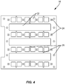
- each baffle 18 has a plurality of airflow spaces 22 formed in it, allowing airflow therethrough.
- a plurality of UV LEDs 24 is mounted on each baffle.
- the UV LEDs 24 are disposed both around the periphery of each baffle 18, and between the airflow spaces 22, so as to maximize the UV illumination of adjacent filter modules 30.
- the UV LEDs 24 are mounted on the interior sides of baffles 18 adjacent the air inlet 12 and outlet 16, and are mounted on both sides of all other baffles 18, so as to illuminate the filter modules 30 from both sides. Mounting UV LEDs 24 on all baffles 18 ensures maximum illumination of all filter modules 30, for maximum photocatalytic effect.
- the efficacy of the VOC removal unit 10 is greatest when the UV LEDs 24 are operated at high power ( ⁇ 500 mA), thus generating a large luminous flux of UV light to activate the photoactive catalysts in the filter modules 30. However, this generates heat, which warms the air flowing through the duct 14, increasing the load on aircraft air conditioning equipment.
- a heat sink is connected to at least one, and preferably to each baffle 18 that includes LEDs 24, using heat sink mounting holes 26. This is done to maintain the life of the UV-LED lights by maintaining lower temperatures on their surface in low flow conditions, prolonging their life. In certain filter configurations (designed for those with higher flow rates) the heat sinks may not be necessary.
- the PCO filter modules 30 are disposed generally transverse to the longitudinal axis 15 of the duct 14, such that air flows through the PCO filter module 30.
- Each PCO filter module 30 contains one or more catalysts which, when illuminated by UV light, are operative to chemically reduce VOCs to non-VOC molecules. Maximum UV illumination of all filters in each filter module 30 is thus desired, to maximize the efficacy of VOC removal. Accordingly, the PCO filter modules 30 are spaced apart from the baffles such that the entirety of both surfaces of each PCO filter module is illuminated by UV light.
- a PCO filter module 30 were directly adjacent a baffle 18, only spots on the surface of the PCO filter module 30 that contact a UV LED 24 would be illuminated.
- the optimal spacing is that distance at which the illumination spots just overlap, fully illuminating the entire facing surface of the PCO filter module 30 - increasing the spacing beyond this distance reduces the luminous flux of UV light.
- the distance between each face of a filter module 30 and the facing baffle 18 is 20mm (dimension "b"); at this distance, 500mA of power applied to the UV LEDs 24 yields a light intensity of over 20mW/cm 2 .
- the filter modules 30 in this aspect are 40mm thick (dimension “c”).
- the baffles 18, measured to the outermost protruding UV LEDs 24, are 15mm thick for those adjacent to the air inlet 12 and outlet 16, which have UV LEDs 24 mounted on only the interior-facing sides (dimension “a"), and 30mm thick for interior baffles 18, which have UV LEDs 24 mounted on both sides (dimension "a*").
- dimensions are exemplary; those of skill in the art may readily deduce optimal relative spacing of components for VOC removal units of different size or shape.
- the filters in each PCO filter module 30 are loaded with some form of titanium dioxide (TiO 2 ).
- Photocatalytic oxidation occurs in the VOC removal unit 10 by illuminating the TiO 2 in the filters with UV light, generating hydroxyl radicals (OH•) by reaction with water molecules in the air.
- the free radicals in turn, oxidize VOCs into non-VOC molecules - primarily carbon dioxide (CO 2 ) and water (H 2 O). These are returned to the aircraft cabin, avoiding the accumulation of contaminants.
- Titanium dioxide is a light-sensitive semiconductor, which absorbs electromagnetic radiation in the near UV region.
- the most common natural form of TiO 2 is the mineral rutile.
- Other forms of TiO 2 are anatase (also known as octahedrite) and brookite (an orthorhombic mineral).
- TiO 2 when used as a photoactive catalyst, is primarily anatase, with a small amount of rutile.
- the anatase form of TiO 2 requires higher light energy than the rutile form, but shows a stronger photoactivity.
- the energy difference between the valence and the conductivity bands of a TiO 2 molecule in the solid state is 3.05eV for rutile and 3.29eV for anatase, corresponding to a photonic absorption band at ⁇ 415 nm for rutile and ⁇ 385 nm for anatase.
- the OH• radicals reduce VOCs to the following end products: organic molecules ⁇ CO 2 + H 2 O organic N-compounds ⁇ HNO 3 + CO 2 + H 2 O organic S-compounds ⁇ H 2 SO 4 + CO 2 + H 2 O organic Cl-compounds ⁇ HCl + CO 2 + H 2 O
- the primary application of photocatalytic oxidation in the VOC removal unit 10 is to reduce VOCs into non-VOC molecules, the process also kills contaminants in bioaerosols, such as bacteria, molds, and fungus. In general, reduction of VOC levels in cabin air enhances comfort of passengers.
- AEROXIDE® P25 is a nanostructured, fine-particulate pure titanium dioxide with high specific surface area. The product is available from Evonik Industries of Parsippany, NJ. AEROXIDE® P25 is a fine white powder with hydrophilic character caused by hydroxyl groups on the surface. It consists of aggregated primary particles. The aggregates are several hundred nm in size and the primary particles have a mean diameter of approximately 21nm. The weight ratio of anatase to rutile is approximately 80/20. AEROXIDE® P25 is sold commercially as a photoactive catalyst.
- AEROXIDE® P25 With its high purity, high specific surface area, and combination of anatase and rutile crystal structure, AEROXIDE® P25 is widely used for catalytic and photocatalytic applications. Other forms of pure TiO 2 may also be used in PCO filter modules 30 in the VOC removal unit 10.
- the inventors have found that doping TiO 2 with iron (Fe-TiO 2 ) and carbon (C-TiO 2 ) yield superior photocatalytic results.
- the UV-PCO reactor relies on sorption of the organic compounds onto the surface of the catalyst to enable breakdown of the compounds. Doping the TiO 2 with carbon or iron increases the sorption capacity of the catalyst, which allows for greater removal of VOCs from the airstream. Through doping with metal and non-metal agents the band gap energy level of TiO 2 is lowered and electron-hole pair mechanism is kept constant with a longer duration for higher light absorption capability which results in better efficiency.
- Table 1 below lists pre- and post-filtering concentrations of various representative VOCs (i.e., ethanol, or EtOH; acetone; and limonene) for pure TiO 2 , Fe-TiO 2 , and C-TiO 2 , when loaded onto various filter media types. It is clear from these data that Fe-TiO 2 , and C-TiO 2 provide superior VOC removal results, as compared to pure TiO 2 .
- VOCs i.e., ethanol, or EtOH; acetone; and limonene
- the photoactive catalyst - whether AEROXIDE® P25, other pure TiO 2 , Fe-TiO 2 , or C-TiO 2 - is loaded into a porous and air- and light-permeable filter.
- the photoactive catalyst is adhered to all surface area of the filter, including within pores and passages running throughout the volume of the filter medium.
- the catalyst is deposited by a dip coating method, followed by drying at 80 -100 °C. Other methods of catalyst deposition may be used.
- Porous metal substrates offer better toughness, better malleability, and lower cost than ceramic substrates.
- using metal substrate generally results in peeling coatings with cracks. This occurs at heating stage and due to difference in thermal expansion coefficients between the TiO 2 and the substrate metal.
- Porous TiO 2 filters are commonly employed to avoid this problem. Such filters are commonly prepared by coating a TiO 2 sol, slurry, or precursor liquid onto ceramic substrates, metal meshes or ceramic or metallic foam by different coating methods. After coating application, heat treatment necessary for photocatalysts activity around 500 °C is generally conducted.
- three filter types are used in PCO filter modules 30: coarse foam, fine foam, and fused quartz filament felt.
- porosity number and size of pores, or voids
- permeability ability of fluid to flow through, which is related to interconnectivity of the pores
- Porosity is important as a large number of pores provide the surface area for adhering more photocatalytic coatings.
- Permeability is important as a large volume of air must flow through the PCO filter modules 30 to remove VCOs from the cabin air of a large aircraft.
- the coarse foam is a relatively open foam, with average pores size of approximately 2540 ⁇ m, and high permeability.
- the coarse foam filter is approximately 10mm thick.
- a suitable coarse foam is available from Recemat BV of the Netherlands. This material can be uniformly coated with catalyst, and is it fairly easy to coat.
- the coarse foam filter allows much of the incident UV light to penetrate the foam, thus illuminating successive filters. For this reason, in some aspects, a coarse foam filter is at both exterior positions of a "stack" of filters forming a PCO filter module 30. The position of coarse foam filter is also maintained on the outside of whole filter stack to start the VOC degradation in a lower specific surface area to very high specific surface area in fine foam filters.
- the fine foam is a denser foam, with average pores size of approximately 800 ⁇ m, and lower permeability as compared to coarse foam but with a higher surface area. Accordingly, the fine foam filter is thinner than the coarse foam filter, at approximately 2-4mm, to maintain robust airflow. This material is more difficult to coat uniformly with catalyst.
- a suitable fine foam is available from Alantum GmbH of Germany.
- a suitable felt of this type is QUARTZEL® felt, available from Magento of the USA.
- the QUARTZEL® felt is difficult to coat uniformly, and presents a high resistance to air flow. Accordingly, it is used sparingly.
- only one of three PCO filter modules 30 in a VOC removal unit 10 include a fused quartz filament filter, and that module 30 includes only a single such filter.
- Each PCO filter module 30 comprises a plurality of catalyst-loaded filters selected and arranged to maximize UV illumination of all of the filters.
- three filter media and four types of photoactive catalysts there are a dozen combinations of PCO filters from which to select. The number of permutations of which of these filters to stack into a filter module 30, in which order, is very large.
- different PCO filter modules - that is, different selections and arrangements of photoactive-catalyst-loaded filters - can be placed in different locations along the duct 14 of the VOC removal unit 10. Of these many possibilities, the inventors have discovered and extensively tested a few near-optimal combinations.
- an aircraft air filtration and volatile organic compound (VOC) removal unit 10 includes an air duct 14 having a longitudinal axis 15, an air inlet 12 at one end, and air outlet 16 at the other end; a plurality of baffles 18 ( Figure 4 ), each having a plurality of open spaces 22 allowing airflow therethrough, disposed at spaced locations within the duct 14 between the air inlet 12 and air outlet 16, the baffles 18 being generally transverse to the longitudinal axis 15; a plurality of ultraviolet (UV) light emitting diodes (LED) 24 mounted on each baffle 18; and a porous and permeable photocatalytic oxidation (PCO) filter module 30 disposed between each pair of baffles 18, generally transverse to the longitudinal axis 15, such that air flows through the PCO filter module 30.
- UV ultraviolet
- LED light emitting diodes
- PCO porous and permeable photocatalytic oxidation
- Each PCO filter module 30 contains one or more catalysts comprising titanium dioxide (TiO 2 ), TiO 2 doped with iron (Fe-TiO 2 ), TiO 2 doped with carbon (C-TiO 2 ), or combinations thereof, which, when illuminated by UV light, are operative to chemically reduce VOCs to non-VOC molecules. This provides a compact, lightweight, low-power means for removing VOCs, which is suited for aircraft.
- the VOC removal unit further includes one or more heat sinks disposed within the duct and adapted to conduct heat away from the UV LEDs away and maintain their lifespan. This prevents overheating of the LEDs to prolong their life in a low flow situation.
- the UV LEDs are disposed both around a periphery of each baffle and between the airflow spaces so as to maximize the UV illumination of adjacent PCO filter modules.
- the UV LEDs are mounted on interior sides of baffles adjacent the air inlet and outlet, and are mounted on both sides of all other baffles, so as to illuminate the PCO filter modules from both sides.
- the PCO filter modules are spaced apart from the baffles such that the entirety of both surfaces of each PCO filter module is illuminated by UV light.
- Each PCO filter module comprises a plurality of filters, each filter selected from the group consisting of a coarse foam, a fine foam, and a fused quartz filament felt, and each filter is loaded with a catalyst which may be one or more of pure titanium dioxide (TiO 2 ), TiO 2 doped with iron (Fe-TiO 2 ), and TiO 2 doped with carbon (C-TiO 2 ), and combinations thereof.
- a catalyst which may be one or more of pure titanium dioxide (TiO 2 ), TiO 2 doped with iron (Fe-TiO 2 ), and TiO 2 doped with carbon (C-TiO 2 ), and combinations thereof.
- each PCO filter module comprises a plurality of catalyst-loaded filters selected and arranged to maximize UV illumination of all of the filters. These materials have high durability and the arrangements facilitate the removal of VOCs.
- the VOC removal unit 10 comprises four baffles 18 and three PCO filter modules 30.
- the PCO filter modules 30 comprise, in order from air inlet 12 to air outlet 16,
- the PCO filter modules 30 comprise, in order from air inlet 12 to air outlet 16,
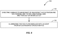
- Figure 6 depicts steps in a method 100 of aircraft air filtration and VOC removal.
- Cabin air is directed to an air inlet 12 of an aircraft air filtration and VOC removal unit 10 comprising an air duct 14 having a longitudinal axis 15, whereby the air flows through airflow spaces 22 in a plurality of baffles 18 disposed at spaced locations within the duct 14 and generally transverse to the longitudinal axis 15, and also through a porous and permeable PCO filter module 30 disposed between each pair of baffles 18 and generally transverse to the longitudinal axis 15, and then out of an air outlet 16 (block 102).
- the PCO filter modules 30 are illuminated with UV light from UV LEDs 24 mounted on each baffle 18 (block 104).
- Each PCO filter module 30 contains one or more catalysts comprising titanium dioxide (TiO 2 ), TiO 2 doped with iron (Fe-TiO 2 ), or TiO 2 doped with carbon (C-TiO 2 ) which, when illuminated by UV light, are operative to chemically reduce VOCs to non-VOC molecules (block 104).
- the method 100 allows for VOC removal from cabin air in a compact, lightweight, low-power manner.
- the method 100 further comprises conducting heat from the UV LEDs away from the airflow via one or more heat sinks disposed within the duct. This prevents excessive heat build-up in the LEDs in a low airflow system.
- the method 100 can include illuminating the PCO filter modules with UV light comprises disposing the UV LEDs both around the periphery of each baffle and between the airflow spaces, so as to maximize the UV illumination of adjacent PCO filter modules. This maximizes the effectiveness of the PCO filter modules 30.
- the method 100 can include disposing the UV LEDs on the baffles comprises disposing the UV LEDs on interior sides of baffles adjacent the air inlet and outlet, and on both sides of all other baffles, so as to illuminate the PCO filter modules from both sides.
- illuminating the PCO filter modules with UV light comprises spacing the PCO filter modules apart from the baffles such that the entirety of both surfaces of each PCO filter module is illuminated by UV light. This provides uniform UV illumination of all filter surfaces, maximizing their effectiveness.
- each PCO filter module comprises one or more filters, each filter selected from the group consisting of a coarse foam, a fine foam, and a fused quartz filament felt, and wherein each filter is loaded with a catalyst which may be one or more of pure titanium dioxide (TiO 2 ), TiO 2 doped with iron (Fe-TiO 2 ), and TiO 2 doped with carbon (C-TiO 2 ). These catalysts enhance VOC removal.
- the method 100 can include illuminating the PCO filter modules with UV light comprises selecting and arranging a plurality of catalyst-loaded filters to form each PCO filter module so as to maximize UV illumination of all of the filters.
- the VOC removal unit comprises four baffles and three PCO filter modules, and the PCO filter modules comprise, in order from air inlet to air outlet, 1) R25 - CTR - TA - R25; 2) CTR - TA - Q25 - R25 - R25; and 3) R25 - CTR - TA - R25, where R25 is a coarse foam loaded with pure TiO 2 ; Q25 is a fused quartz filament felt loaded with pure TiO 2 ; CTR is a coarse foam loaded with C-TiO 2 and TA is a fine foam loaded with pure TiO 2 .
- the PCO filter modules comprise, in order from air inlet to air outlet, 1) R25 - TA - FTR - CTR; 2) R25 - CTA - FTR - Q25 - R25; and 3) R25 - TA - FTR - CTR; where FTR is a coarse foam loaded with Fe-TiO2.
- the method 100 further comprises filtering contaminants from the airflow by directing the air through an activated carbon filter. This assists in contaminant removal.
- Photocatalytic oxidation is a known effective means of VOC removal. See Stevens, et al., Investigation of the Photocatalytic Oxidation of Low-Level Carbonyl Compounds, J. Air Waste Manag. Assoc. 1998 Oct; 48(10): 979-984 ("PCO of the formaldehyde and acetone was nearly 100% for all reactor designs.”). See also, Hodgson, et al., Performance of ultraviolet photocatalytic oxidation for indoor air cleaning applications, Indoor Air 2007; 17: 305-316 (conversion rate of 80% for 27 VOCs characteristic of office buildings and 10 VOCs emitted by cleaning products). These implementations were generally large, heavy, and utilized large amounts of power, primarily to drive banks of UV lamps.
- the VOC removal unit 10 provides a compact, lightweight, low-power implementation of photocatalytic oxidation, allowing for its use on aircraft.
Landscapes
- Chemical & Material Sciences (AREA)
- Engineering & Computer Science (AREA)
- Chemical Kinetics & Catalysis (AREA)
- Health & Medical Sciences (AREA)
- Environmental & Geological Engineering (AREA)
- Oil, Petroleum & Natural Gas (AREA)
- Analytical Chemistry (AREA)
- General Chemical & Material Sciences (AREA)
- Biomedical Technology (AREA)
- Materials Engineering (AREA)
- Organic Chemistry (AREA)
- General Health & Medical Sciences (AREA)
- Pulmonology (AREA)
- Aviation & Aerospace Engineering (AREA)
- Toxicology (AREA)
- Life Sciences & Earth Sciences (AREA)
- Animal Behavior & Ethology (AREA)
- Epidemiology (AREA)
- Public Health (AREA)
- Veterinary Medicine (AREA)
- Catalysts (AREA)
- Exhaust Gas Treatment By Means Of Catalyst (AREA)
Abstract
Description
- The present disclosure relates generally to aircraft, and in particular to a system and method for the removal of Volatile Organic Compounds (VOC) in an aircraft.
- Volatile organic compounds (VOC) are a class of organic chemicals characterized by a high vapor pressure at room temperature, typically resulting from a low boiling point. They include non-methane hydrocarbons (NMHC) and oxygenated NMHC (e.g., alcohols, aldehydes and organic acids). VOCs emanate from off-gassing of foams, plastics, fabrics, and other manufactured products, particularly when they are new, and from the solvents in many cleaning products. VOCs are also produced as byproducts of human metabolic processes. Over 200 VOCs have been identified in human alveolar breath. In a closed environment full of people, such as a passenger aircraft, endogenously produced VOCs dominate.
- From measurement campaigns, the primary complaints from passengers and crew in the aircraft are eye, nasal tract and throat irritation. Industry (FAA CoE ACER, ASHRAE) research has shown that many of these complaints are sourced from gaseous contaminants, notably VOCs.
- VOCs cannot be removed by typical air filtration methods such as HEPA filtration. Existing systems to reduce VOC concentration in the cabin environment include activated carbon.
- The Background section of this document is provided to place aspects of the present disclosure in technological and operational context, to assist those of skill in the art in understanding their scope and utility. Unless explicitly identified as such, no statement herein is admitted to be prior art merely by its inclusion in the Background section.
- The following presents a simplified summary of the disclosure in order to provide a basic understanding to those of skill in the art. This summary is not an extensive overview of the disclosure and is not intended to identify key/critical elements of aspects of the disclosure or to delineate the scope of the disclosure. The sole purpose of this summary is to present some concepts disclosed herein in a simplified form as a prelude to the more detailed description that is presented later.
- According to one or more aspects of the present disclosure described and claimed herein, a compact, lightweight, low power aircraft air filtration and VOC removal unit enables the removal of VOCs from cabin air in, e.g., a passenger aircraft. Cabin air is directed through a duct. Transverse to a longitudinal axis of the duct, a plurality of baffles having air flow-through airflow spaces are spaced apart along the axis. Ultraviolet (UV) LEDs are mounted on the interior sides of the outermost baffles, and on both sides of all interior baffles. A filter module is disposed between pairs of baffles, transverse to the longitudinal axis, and spaced from the baffles sufficiently to illuminate the entirety of both sides. Each filter modules comprises a plurality of filters, selected and arranged so as to maximize UV illumination of all filters in the module. For each filter module, the filters are selected from a coarse foam, a fine foam, and a fused quartz felt. Each filter is loaded with a catalyst selected from AEROXIDE® P25, titanium dioxide (TiO2), TiO2 doped with iron (Fe-TiO2), and TiO2 doped with carbon (C-TiO2). The catalysts on the filters, under UV illumination, chemically reduce VOCs in the airflow to non-VOC molecules.
- One aspect relates to an aircraft air filtration and volatile organic compound (VOC) removal unit. The VOC removal unit includes an air duct having a longitudinal axis, an air inlet at one end, and air outlet at the other end; a plurality of baffles, each having a plurality of open spaces allowing airflow therethrough, disposed at spaced locations within the duct between the air inlet and outlet, the baffles being generally transverse to the longitudinal axis; a plurality of ultraviolet (UV) light emitting diodes (LED) mounted on each baffle; and a porous and permeable photocatalytic oxidation (PCO) filter module disposed between each pair of baffles, generally transverse to the longitudinal axis, such that air flows through the PCO filter module. Each PCO filter module contains one or more catalysts comprising titanium dioxide (TiO2), TiO2 doped with iron (Fe-TiO2), or TiO2 doped with carbon (C-TiO2) which, when illuminated by UV light, are operative to chemically reduce VOCs to non-VOC molecules.
- Another aspect relates to a method of aircraft air filtration and volatile organic compound (VOC) removal. Cabin air is directed to an air inlet of an aircraft air filtration and VOC removal unit comprising an air duct having a longitudinal axis, whereby the air flows through open spaces in a plurality of baffles disposed at spaced locations within the duct and generally transverse to the longitudinal axis, and also through a porous and permeable photocatalytic oxidation (PCO) filter module disposed between each pair of baffles and generally transverse to the longitudinal axis, and then out of an air outlet. The PCO filter modules are illuminated with ultraviolet (UV) light from UV light emitting diodes (LED) mounted on each baffle. Each PCO filter module contains one or more catalysts comprising titanium dioxide (TiO2), TiO2 doped with iron (Fe-TiO2), or TiO2 doped with carbon (C-TiO2) which, when illuminated by UV light, are operative to chemically reduce VOCs to non-VOC molecules.
- The present disclosure will now be described more fully hereinafter with reference to the accompanying drawings, in which aspects of the disclosure are shown. However, this disclosure should not be construed as limited to the aspects set forth herein. Rather, these aspects are provided so that this disclosure will be thorough and complete, and will fully convey the scope of the disclosure to those skilled in the art. Like numbers refer to like elements throughout.
-
Figure 1 is a perspective view of an example aircraft air filtration and VOC removal unit. -
Figure 2 is a plan view of the example VOC removal unit, showing dimensions according to one aspect. -
Figure 3 is a cross-section view of the example VOC removal unit, showing dimensions of the inlet/outlet and duct according to one aspect. -
Figure 4 is a side view of an example baffle. -
Figure 5 is a section view of the example VOC removal unit showing the spatial relationship between baffles, UV LEDs, and filter modules. -
Figure 6 is a flow diagram of an exemplary method of aircraft air filtration and VOC removal. - For simplicity and illustrative purposes, the present disclosure is described by referring mainly to an exemplary aspect thereof. In the following description, numerous specific details are set forth in order to provide a thorough understanding of the present disclosure. However, it will be readily apparent to one of ordinary skill in the art that the aspects of the present disclosure can be practiced without limitation to these specific details. In this description, well known methods and structures have not been described in detail so as not to unnecessarily obscure the present disclosure.
-
Figure 1 depicts an example compact, lightweight, low power aircraft air filtration and VOC removal unit 10 (hereinafter referred to as simply a "VOC removal unit" 10), according to one aspect of the present disclosure. TheVOC removal unit 10 operates to remove VOCs from cabin air by photocatalytic oxidation (PCO), as will be explained in greater detail herein. The VOCremoval unit 10 is designed specifically for use on an aircraft. Accordingly, it is small and lightweight. The design maximizes airflow through theVOC removal unit 10, and minimizes heat generation and a thermal gradient across it, consistent with the maximum achievable UV illumination of PCO filters. Numerous aspects of component design, placement, and spacing achieve this optimization. -
Figure 1 is a perspective view of an exampleVOC removal unit 10, with one side removed to reveal internal components.Figures 2 and 3 are sections views of theVOC removal unit 10 according to one aspect, andFigure 5 is a section view showing the spacing and relationship of various components. - The
VOC removal unit 10 comprises anair inlet 12, aduct 14 having alongitudinal axis 15, and anair outlet 16. In the representative aspect of theVOC removal unit 10 depicted in the figures, theair inlet 12 andoutlet 16 have a circular cross-sectional shape, and theduct 14 has a square cross-section. However, those of skill in the art will readily recognize that other shapes can be utilized, within the scope of the present disclosure. -
Figure 5 depicts the overall operative structure of theVOC removal unit 10. A plurality ofbaffles 18 is disposed at spaced locations within theduct 14. Between each pair ofbaffles 18, aPCO filter module 30 comprises a plurality of filters, each of which is loaded with a photoactive catalyst. The number and spacing (as explained further below) ofbaffles 18 andPCO filter modules 30 is representative. In other aspects, more or fewer of each may be provided. In general, the number ofbaffles 18 will always exceed the number ofPCO filter modules 30 by one - withbaffles 18 disposed at both ends and in between each pair ofPCO filter modules 30. Ultraviolet (UV) light emitting diodes (LED) 24 mounted on thebaffles 18 illuminate both sides of thefilter modules 30 with UV light to maximize illumination of photocatalytic coatings on material in thefilter modules 30. Since the photocatalytic coatings require UV light as a catalyst to convert VOCs to non-VOC molecules, maximizing the illumination ofPCO modules 30 with UV light maximizes the effectiveness of theVOC removal unit 10. Cabin air directed through theVOC removal unit 10 passes through the baffles andPCO filter modules 30. As explained further herein, UV light illuminating thePCO filter modules 30 photoactivates catalysts loaded therein, initiating a chemical photocatalytic oxidation process that reduces VCOs in the air to non-VCO molecules, such as carbon dioxide and water. - The
baffles 18 are disposed at spaced locations within theduct 14, between theair inlet 12 andair outlet 16. Thebaffles 18 are disposed generally transverse to thelongitudinal axis 15 of theduct 14. As depicted inFigure 4 , eachbaffle 18 has a plurality ofairflow spaces 22 formed in it, allowing airflow therethrough. A plurality ofUV LEDs 24 is mounted on each baffle. TheUV LEDs 24 are disposed both around the periphery of eachbaffle 18, and between theairflow spaces 22, so as to maximize the UV illumination ofadjacent filter modules 30. TheUV LEDs 24 are mounted on the interior sides ofbaffles 18 adjacent theair inlet 12 andoutlet 16, and are mounted on both sides of allother baffles 18, so as to illuminate thefilter modules 30 from both sides. MountingUV LEDs 24 on allbaffles 18 ensures maximum illumination of allfilter modules 30, for maximum photocatalytic effect. - The efficacy of the
VOC removal unit 10 is greatest when theUV LEDs 24 are operated at high power (∼500 mA), thus generating a large luminous flux of UV light to activate the photoactive catalysts in thefilter modules 30. However, this generates heat, which warms the air flowing through theduct 14, increasing the load on aircraft air conditioning equipment. In one aspect a heat sink is connected to at least one, and preferably to eachbaffle 18 that includesLEDs 24, using heat sink mounting holes 26. This is done to maintain the life of the UV-LED lights by maintaining lower temperatures on their surface in low flow conditions, prolonging their life. In certain filter configurations (designed for those with higher flow rates) the heat sinks may not be necessary. - A porous and permeable
PCO filter module 30, comprising a plurality or "stack" of filters, is disposed between eachbaffle 18. ThePCO filter modules 30 are disposed generally transverse to thelongitudinal axis 15 of theduct 14, such that air flows through thePCO filter module 30. EachPCO filter module 30 contains one or more catalysts which, when illuminated by UV light, are operative to chemically reduce VOCs to non-VOC molecules. Maximum UV illumination of all filters in eachfilter module 30 is thus desired, to maximize the efficacy of VOC removal. Accordingly, thePCO filter modules 30 are spaced apart from the baffles such that the entirety of both surfaces of each PCO filter module is illuminated by UV light. - If a
PCO filter module 30 were directly adjacent abaffle 18, only spots on the surface of thePCO filter module 30 that contact aUV LED 24 would be illuminated. As the spacing between thePCO filter module 30 and thebaffle 18 increases, the illumination spot sizes grow and the photonic efficiency decreases. The optimal spacing is that distance at which the illumination spots just overlap, fully illuminating the entire facing surface of the PCO filter module 30 - increasing the spacing beyond this distance reduces the luminous flux of UV light. In the aspect depicted inFigure 5 , the distance between each face of afilter module 30 and the facingbaffle 18 is 20mm (dimension "b"); at this distance, 500mA of power applied to theUV LEDs 24 yields a light intensity of over 20mW/cm2. Thefilter modules 30 in this aspect are 40mm thick (dimension "c"). In the aspect depicted, thebaffles 18, measured to the outermost protrudingUV LEDs 24, are 15mm thick for those adjacent to theair inlet 12 andoutlet 16, which haveUV LEDs 24 mounted on only the interior-facing sides (dimension "a"), and 30mm thick forinterior baffles 18, which haveUV LEDs 24 mounted on both sides (dimension "a*"). These dimensions are exemplary; those of skill in the art may readily deduce optimal relative spacing of components for VOC removal units of different size or shape. - The filters in each
PCO filter module 30 are loaded with some form of titanium dioxide (TiO2). Photocatalytic oxidation occurs in theVOC removal unit 10 by illuminating the TiO2 in the filters with UV light, generating hydroxyl radicals (OH•) by reaction with water molecules in the air. The free radicals, in turn, oxidize VOCs into non-VOC molecules - primarily carbon dioxide (CO2) and water (H2O). These are returned to the aircraft cabin, avoiding the accumulation of contaminants. - Titanium dioxide is a light-sensitive semiconductor, which absorbs electromagnetic radiation in the near UV region. The most common natural form of TiO2 is the mineral rutile. Other forms of TiO2 are anatase (also known as octahedrite) and brookite (an orthorhombic mineral). TiO2, when used as a photoactive catalyst, is primarily anatase, with a small amount of rutile. The anatase form of TiO2 requires higher light energy than the rutile form, but shows a stronger photoactivity. The energy difference between the valence and the conductivity bands of a TiO2 molecule in the solid state is 3.05eV for rutile and 3.29eV for anatase, corresponding to a photonic absorption band at <415 nm for rutile and <385 nm for anatase.
- Absorption of light energy causes an electron to be promoted from the valence band to the conduction band. This electron, and the simultaneously created positive "electron hole," can move on the surface of the solid, where it can take part in redox reactions. In particular, water molecules in vapor state in the air are adsorbed onto the TiO2 surface where they react with the free electron, generating hydroxyl radicals (OH•). These radicals are uncharged, short-lived, highly reactive forms of hydroxide ions (OH-), bearing considerable oxidizing power. The OH• radicals can cause complete oxidation of organic compounds to carbon dioxide and water. In some aspects, the OH• radicals reduce VOCs to the following end products:
organic molecules → CO2 + H2O
organic N-compounds → HNO3 + CO2 + H2O
organic S-compounds → H2SO4 + CO2 + H2O
organic Cl-compounds → HCl + CO2 + H2O
Although the primary application of photocatalytic oxidation in theVOC removal unit 10 is to reduce VOCs into non-VOC molecules, the process also kills contaminants in bioaerosols, such as bacteria, molds, and fungus. In general, reduction of VOC levels in cabin air enhances comfort of passengers. - The photoactivity of TiO2 is known, and has commercial applications. AEROXIDE® P25 is a nanostructured, fine-particulate pure titanium dioxide with high specific surface area. The product is available from Evonik Industries of Parsippany, NJ. AEROXIDE® P25 is a fine white powder with hydrophilic character caused by hydroxyl groups on the surface. It consists of aggregated primary particles. The aggregates are several hundred nm in size and the primary particles have a mean diameter of approximately 21nm. The weight ratio of anatase to rutile is approximately 80/20. AEROXIDE® P25 is sold commercially as a photoactive catalyst. With its high purity, high specific surface area, and combination of anatase and rutile crystal structure, AEROXIDE® P25 is widely used for catalytic and photocatalytic applications. Other forms of pure TiO2 may also be used in
PCO filter modules 30 in theVOC removal unit 10. - Additionally, the inventors have found that doping TiO2 with iron (Fe-TiO2) and carbon (C-TiO2) yield superior photocatalytic results. The UV-PCO reactor relies on sorption of the organic compounds onto the surface of the catalyst to enable breakdown of the compounds. Doping the TiO2 with carbon or iron increases the sorption capacity of the catalyst, which allows for greater removal of VOCs from the airstream. Through doping with metal and non-metal agents the band gap energy level of TiO2 is lowered and electron-hole pair mechanism is kept constant with a longer duration for higher light absorption capability which results in better efficiency.
- Table 1 below lists pre- and post-filtering concentrations of various representative VOCs (i.e., ethanol, or EtOH; acetone; and limonene) for pure TiO2, Fe-TiO2, and C-TiO2, when loaded onto various filter media types. It is clear from these data that Fe-TiO2, and C-TiO2 provide superior VOC removal results, as compared to pure TiO2.
Table 1 - Relative Performance of Photoactive Catalysts Substrate VOC Type Initial VOC Concentration (ppb) Final VOC Concentration (ppb) Efficiency pure TiO2 Coarse Foam EtOH 423.40 350.22 17.2% Acetone 117.30 78.80 32.8% Fine Foam EtOH NA NA NA Acetone NA NA NA Coarse/Fine Foam EtOH 449.00 320.20 28.6% Acetone NA NA NA Fe-doped TiO2 Coarse Foam EtOH 389.20 198.70 48.9% Acetone 74.50 30.30 59.3% Fine Foam EtOH NA NA NA Acetone NA NA NA Coarse/Fine Foam EtOH 499.30 196.70 60.6% Acetone NA NA NA Limonene 39.30 9.30 68.7% C-doped TiO2 Coarse Foam EtOH NA NA NA Acetone NA NA NA Fine Foam EtOH NA NA NA Acetone NA NA NA Coarse/Fine Foam EtOH 417.40 203.45 51.2% Acetone 152.30 80.90 46.8% NA: Not
Available - The photoactive catalyst - whether AEROXIDE® P25, other pure TiO2, Fe-TiO2, or C-TiO2 - is loaded into a porous and air- and light-permeable filter. In one aspect, the photoactive catalyst is adhered to all surface area of the filter, including within pores and passages running throughout the volume of the filter medium. In at least one aspect, the catalyst is deposited by a dip coating method, followed by drying at 80 -100 °C. Other methods of catalyst deposition may be used.
- The type of substrate and coating methods have important effects on coating stability, photocatalytic, and mechanical performance of the filters. Porous metal substrates offer better toughness, better malleability, and lower cost than ceramic substrates. However, using metal substrate generally results in peeling coatings with cracks. This occurs at heating stage and due to difference in thermal expansion coefficients between the TiO2 and the substrate metal.
- Porous TiO2 filters are commonly employed to avoid this problem. Such filters are commonly prepared by coating a TiO2 sol, slurry, or precursor liquid onto ceramic substrates, metal meshes or ceramic or metallic foam by different coating methods. After coating application, heat treatment necessary for photocatalysts activity around 500 °C is generally conducted.
- In one aspect, three filter types are used in PCO filter modules 30: coarse foam, fine foam, and fused quartz filament felt. Both the porosity (number and size of pores, or voids) and the permeability (ability of fluid to flow through, which is related to interconnectivity of the pores) of each type of filter type are important. Porosity is important as a large number of pores provide the surface area for adhering more photocatalytic coatings. Permeability is important as a large volume of air must flow through the
PCO filter modules 30 to remove VCOs from the cabin air of a large aircraft. - The coarse foam is a relatively open foam, with average pores size of approximately 2540µm, and high permeability. The coarse foam filter is approximately 10mm thick. A suitable coarse foam is available from Recemat BV of the Netherlands. This material can be uniformly coated with catalyst, and is it fairly easy to coat. The coarse foam filter allows much of the incident UV light to penetrate the foam, thus illuminating successive filters. For this reason, in some aspects, a coarse foam filter is at both exterior positions of a "stack" of filters forming a
PCO filter module 30. The position of coarse foam filter is also maintained on the outside of whole filter stack to start the VOC degradation in a lower specific surface area to very high specific surface area in fine foam filters. - The fine foam is a denser foam, with average pores size of approximately 800µm, and lower permeability as compared to coarse foam but with a higher surface area. Accordingly, the fine foam filter is thinner than the coarse foam filter, at approximately 2-4mm, to maintain robust airflow. This material is more difficult to coat uniformly with catalyst. A suitable fine foam is available from Alantum GmbH of Germany.
- Another type of material is made from fused quartz filaments. A suitable felt of this type is QUARTZEL® felt, available from Magento of the USA. The QUARTZEL® felt is difficult to coat uniformly, and presents a high resistance to air flow. Accordingly, it is used sparingly. In one aspect, only one of three
PCO filter modules 30 in aVOC removal unit 10 include a fused quartz filament filter, and thatmodule 30 includes only a single such filter. - Each
PCO filter module 30 comprises a plurality of catalyst-loaded filters selected and arranged to maximize UV illumination of all of the filters. With, in some aspect, three filter media and four types of photoactive catalysts, there are a dozen combinations of PCO filters from which to select. The number of permutations of which of these filters to stack into afilter module 30, in which order, is very large. Furthermore, different PCO filter modules - that is, different selections and arrangements of photoactive-catalyst-loaded filters - can be placed in different locations along theduct 14 of theVOC removal unit 10. Of these many possibilities, the inventors have discovered and extensively tested a few near-optimal combinations. - In one aspect, as depicted in
Figure 5 , an aircraft air filtration and volatile organic compound (VOC)removal unit 10 includes anair duct 14 having alongitudinal axis 15, anair inlet 12 at one end, andair outlet 16 at the other end; a plurality of baffles 18 (Figure 4 ), each having a plurality ofopen spaces 22 allowing airflow therethrough, disposed at spaced locations within theduct 14 between theair inlet 12 andair outlet 16, thebaffles 18 being generally transverse to thelongitudinal axis 15; a plurality of ultraviolet (UV) light emitting diodes (LED) 24 mounted on eachbaffle 18; and a porous and permeable photocatalytic oxidation (PCO)filter module 30 disposed between each pair ofbaffles 18, generally transverse to thelongitudinal axis 15, such that air flows through thePCO filter module 30. EachPCO filter module 30 contains one or more catalysts comprising titanium dioxide (TiO2), TiO2 doped with iron (Fe-TiO2), TiO2 doped with carbon (C-TiO2), or combinations thereof, which, when illuminated by UV light, are operative to chemically reduce VOCs to non-VOC molecules. This provides a compact, lightweight, low-power means for removing VOCs, which is suited for aircraft. - In one aspect, the VOC removal unit further includes one or more heat sinks disposed within the duct and adapted to conduct heat away from the UV LEDs away and maintain their lifespan. This prevents overheating of the LEDs to prolong their life in a low flow situation.
- In one aspect, the UV LEDs are disposed both around a periphery of each baffle and between the airflow spaces so as to maximize the UV illumination of adjacent PCO filter modules. The UV LEDs are mounted on interior sides of baffles adjacent the air inlet and outlet, and are mounted on both sides of all other baffles, so as to illuminate the PCO filter modules from both sides. The PCO filter modules are spaced apart from the baffles such that the entirety of both surfaces of each PCO filter module is illuminated by UV light. These features ensure maximum and even illumination of the PCO filter modules by UV light.
- Each PCO filter module comprises a plurality of filters, each filter selected from the group consisting of a coarse foam, a fine foam, and a fused quartz filament felt, and each filter is loaded with a catalyst which may be one or more of pure titanium dioxide (TiO2), TiO2 doped with iron (Fe-TiO2), and TiO2 doped with carbon (C-TiO2), and combinations thereof. In one aspect, each PCO filter module comprises a plurality of catalyst-loaded filters selected and arranged to maximize UV illumination of all of the filters. These materials have high durability and the arrangements facilitate the removal of VOCs.
- The
VOC removal unit 10 comprises fourbaffles 18 and threePCO filter modules 30. ThePCO filter modules 30 comprise, in order fromair inlet 12 toair outlet 16, - 1) R25 - CTR - TA - R25;
- 2) CTR - TA - Q25 - R25 - R25; and
- 3) R25 - CTR - TA - R25; where
- R25 is a coarse foam loaded with pure TiO2;
- Q25 is a fused quartz filament felt loaded with pure TiO2;
- CTR is a coarse foam loaded with C-TiO2 and
- TA is a fine foam loaded with pure TiO2.
- In another aspect, with the same numbers of
baffles 18 andPCO filter modules 30, thePCO filter modules 30 comprise, in order fromair inlet 12 toair outlet 16, - 1) R25 - TA - FTR - CTR;
- 2) R25 - CTA - FTR - Q25 - R25; and
- 3) R25 - TA - FTR - CTR; where
FTR is a coarse foam loaded with Fe-TiO2. - Based on the information disclosed herein, those of skill in the art may devise numerous other selections and arrangements of both photoactive catalyst-loaded filters in each
PCO filter module 30, and thePCO filter modules 30 in theVOC removal unit 10, within the scope of the present disclosure. -
Figure 6 depicts steps in amethod 100 of aircraft air filtration and VOC removal. Cabin air is directed to anair inlet 12 of an aircraft air filtration andVOC removal unit 10 comprising anair duct 14 having alongitudinal axis 15, whereby the air flows throughairflow spaces 22 in a plurality ofbaffles 18 disposed at spaced locations within theduct 14 and generally transverse to thelongitudinal axis 15, and also through a porous and permeablePCO filter module 30 disposed between each pair ofbaffles 18 and generally transverse to thelongitudinal axis 15, and then out of an air outlet 16 (block 102). ThePCO filter modules 30 are illuminated with UV light fromUV LEDs 24 mounted on each baffle 18 (block 104). EachPCO filter module 30 contains one or more catalysts comprising titanium dioxide (TiO2), TiO2 doped with iron (Fe-TiO2), or TiO2 doped with carbon (C-TiO2) which, when illuminated by UV light, are operative to chemically reduce VOCs to non-VOC molecules (block 104). Themethod 100 allows for VOC removal from cabin air in a compact, lightweight, low-power manner. - The
method 100 further comprises conducting heat from the UV LEDs away from the airflow via one or more heat sinks disposed within the duct. This prevents excessive heat build-up in the LEDs in a low airflow system. - The
method 100 can include illuminating the PCO filter modules with UV light comprises disposing the UV LEDs both around the periphery of each baffle and between the airflow spaces, so as to maximize the UV illumination of adjacent PCO filter modules. This maximizes the effectiveness of thePCO filter modules 30. - The
method 100 can include disposing the UV LEDs on the baffles comprises disposing the UV LEDs on interior sides of baffles adjacent the air inlet and outlet, and on both sides of all other baffles, so as to illuminate the PCO filter modules from both sides. In one aspect of themethod 100, illuminating the PCO filter modules with UV light comprises spacing the PCO filter modules apart from the baffles such that the entirety of both surfaces of each PCO filter module is illuminated by UV light. This provides uniform UV illumination of all filter surfaces, maximizing their effectiveness. - In one aspect of the
method 100, each PCO filter module comprises one or more filters, each filter selected from the group consisting of a coarse foam, a fine foam, and a fused quartz filament felt, and wherein each filter is loaded with a catalyst which may be one or more of pure titanium dioxide (TiO2), TiO2 doped with iron (Fe-TiO2), and TiO2 doped with carbon (C-TiO2). These catalysts enhance VOC removal. - The
method 100 can include illuminating the PCO filter modules with UV light comprises selecting and arranging a plurality of catalyst-loaded filters to form each PCO filter module so as to maximize UV illumination of all of the filters. In one aspect, the VOC removal unit comprises four baffles and three PCO filter modules, and the PCO filter modules comprise, in order from air inlet to air outlet, 1) R25 - CTR - TA - R25; 2) CTR - TA - Q25 - R25 - R25; and 3) R25 - CTR - TA - R25, where R25 is a coarse foam loaded with pure TiO2; Q25 is a fused quartz filament felt loaded with pure TiO2; CTR is a coarse foam loaded with C-TiO2 and TA is a fine foam loaded with pure TiO2. In another aspect, the PCO filter modules comprise, in order from air inlet to air outlet, 1) R25 - TA - FTR - CTR; 2) R25 - CTA - FTR - Q25 - R25; and 3) R25 - TA - FTR - CTR; where FTR is a coarse foam loaded with Fe-TiO2. These particular selections and arrangements provide good VOC removal performance. - The
method 100 further comprises filtering contaminants from the airflow by directing the air through an activated carbon filter. This assists in contaminant removal. - Photocatalytic oxidation is a known effective means of VOC removal. See Stevens, et al., Investigation of the Photocatalytic Oxidation of Low-Level Carbonyl Compounds, J. Air Waste Manag. Assoc. 1998 Oct; 48(10): 979-984 ("PCO of the formaldehyde and acetone was nearly 100% for all reactor designs."). See also, Hodgson, et al., Performance of ultraviolet photocatalytic oxidation for indoor air cleaning applications, Indoor Air 2007; 17: 305-316 (conversion rate of 80% for 27 VOCs characteristic of office buildings and 10 VOCs emitted by cleaning products). These implementations were generally large, heavy, and utilized large amounts of power, primarily to drive banks of UV lamps. By utilizing
UV LEDs 24 illuminating both sides ofPCO filter modules 30 designed to transmit the UV light deep into thePCO filter modules 30 to illuminate, and thus photoactivate, catalysts loaded therein, theVOC removal unit 10 provides a compact, lightweight, low-power implementation of photocatalytic oxidation, allowing for its use on aircraft. - Further, the disclosure comprises examples according to the following clauses:
- Clause 1. An aircraft air filtration and volatile organic compound (VOC) removal unit, comprising: an air duct having a longitudinal axis, an air inlet at one end, and air outlet at the other end; a plurality of baffles, each having a plurality of airflow spaces allowing airflow therethrough, disposed at spaced locations within the duct between the air inlet and air outlet, the baffles being generally transverse to the longitudinal axis; a plurality of ultraviolet (UV) light emitting diodes (LED) mounted on each baffle; and a porous and permeable photocatalytic oxidation (PCO) filter module disposed between each pair of baffles, generally transverse to the longitudinal axis, such that air flows through the PCO filter module; wherein each PCO filter module contains one or more catalysts comprising titanium dioxide (TiO2), TiO2 doped with iron (Fe-TiO2), TiO2 doped with carbon (C-TiO2), or combinations thereof which, when illuminated by UV light, are operative to chemically reduce VOCs to non-VOC molecules.
- Clause 2. The VOC removal unit of Clause 1 further comprising one or more heat sinks disposed within the duct and adapted to conduct heat away from the UV LEDs to prolong their lifespan.
- Clause 3. The VOC removal unit of Clause 1 wherein the UV LEDs are disposed both around a periphery of each baffle and between the airflow spaces so as to maximize UV illumination of an adjacent PCO filter module.
- Clause 4. The VOC removal unit of Clause 3 wherein UV LEDs are mounted on interior sides of baffles adjacent the air inlet and outlet, and are mounted on both sides of all other baffles, so as to illuminate each PCO filter module from both sides.
- Clause 5. The VOC removal unit of Clause 4 wherein the PCO filter module is spaced apart from the baffles such that all of both surfaces of each PCO filter module is illuminated by UV light.
- Clause 6. The VOC removal unit of any of Clauses 1-5 wherein each PCO filter module comprises a plurality of filters, each filter including one or more of a coarse foam, a fine foam, a fused quartz filament felt, or combination thereof, and wherein each filter is loaded with a catalyst including one or more of pure titanium dioxide (TiO2), TiO2 doped with iron (Fe-TiO2), TiO2 doped with carbon (C-TiO2), or combination thereof.
- Clause 7. The VOC removal unit of Clause 6 wherein each PCO filter module comprises a plurality of catalyst-loaded filters selected and arranged to maximize UV illumination of all of the filters and through a complete depth of each filter layer.
- Clause 8. The VOC removal unit of Clause 7 wherein the VOC removal unit comprises four baffles and three PCO filter modules, and wherein the PCO filter modules comprise, in order from air inlet to air outlet,
- 1) R25 - CTR - TA - R25;
- 2) CTR - TA - Q25 - R25 - R25; and
- 3) R25 - CTR - TA - R25, where
- R25 is a coarse foam loaded with pure TiO2;
- Q25 is a fused quartz filament felt loaded with pure TiO2;
- CTR is a coarse foam loaded with C-TiO2 and
- TA is a fine foam loaded with pure TiO2.
- Clause 9. The VOC removal unit of Clause 7 wherein the VOC removal unit comprises four baffles and three PCO filter modules, and wherein the PCO filter modules comprise, in order from air inlet to air outlet,
- 1) R25 - TA - FTR - CTR;
- 2) R25 - CTA - FTR - Q25 - R25; and
- 3) R25 - TA - FTR - CTR; where
- R25 is a coarse foam loaded with pure TiO2;
- Q25 is a fused quartz filament felt loaded with pure TiO2;
- CTR is a coarse foam loaded with C-TiO2;
- TA is a fine foam loaded with pure TiO2; and
- FTR is a coarse foam loaded with Fe-TiO2.
-
Clause 10. A method of aircraft air filtration and volatile organic compound (VOC) removal, comprising: directing cabin air to an air inlet of an aircraft air filtration and VOC removal unit comprising an air duct having a longitudinal axis, whereby the air flows through airflow spaces in a plurality of baffles disposed at spaced locations within the duct and generally transverse to the longitudinal axis, and also through a porous and permeable photocatalytic oxidation (PCO) filter module disposed between each pair of baffles and generally transverse to the longitudinal axis, and then out of an air outlet; and illuminating the PCO filter modules with ultraviolet (UV) light from UV light emitting diodes (LED) mounted on each baffle; wherein each PCO filter module contains one or more catalysts comprising titanium dioxide (TiO2), TiO2 doped with iron (Fe-TiO2), or TiO2 doped with carbon (C-TiO2) which, when illuminated by UV light, are operative to chemically reduce VOCs to non-VOC molecules. - Clause 11. The method of
Clause 10 further comprising conducting heat from the UV LEDs away from the LEDs via one or more heat sinks disposed within the duct. -
Clause 12. The method ofClause 10 or 11 wherein illuminating the PCO filter modules with UV light comprises disposing the UV LEDs both around a periphery of each baffle and between the airflow spaces, so as to maximize the UV illumination of adjacent PCO filter modules. - Clause 13. The method of
Clause 12 wherein disposing the UV LEDs on the baffles comprises disposing the UV LEDs on interior sides of baffles adjacent the air inlet and outlet, and on both sides of all other baffles, so as to illuminate each PCO filter module from both sides. -
Clause 14. The method of Clause 13 wherein illuminating each PCO filter module with UV light comprises spacing each PCO filter module apart from the baffles such that an entirety of both surfaces of each PCO filter module is illuminated by UV light. -
Clause 15. The method of any of Clauses 10-14 wherein each PCO filter module comprises one or more filters, each filter including one or more of a coarse foam, a fine foam, a fused quartz filament felt, and combinations thereof, and wherein each filter is loaded with a catalyst including one or more of pure titanium dioxide (TiO2), TiO2 doped with iron (Fe-TiO2), TiO2 doped with carbon (C-TiO2), and combinations thereof. -
Clause 16. The method ofClause 15 wherein illuminating the PCO filter modules with UV light comprises selecting and arranging a plurality of catalyst-loaded filters to form each PCO filter module so as to maximize UV illumination of all of the filters. - Clause 17. The method of
Clause 16 wherein the VOC removal unit comprises four baffles and three PCO filter modules, and wherein the PCO filter modules comprise, in order from air inlet to air outlet,- 1) R25 - CTR - TA - R25;
- 2) CTR - TA - Q25 - R25 - R25; and
- 3) R25 - CTR - TA - R25, where
- R25 is a coarse foam loaded with pure TiO2;
- Q25 is a fused quartz filament felt loaded with pure TiO2;
- CTR is a coarse foam loaded with C-TiO2 and
- TA is a fine foam loaded with pure TiO2.
-
Clause 18. The method ofClause 16 wherein the VOC removal unit comprises four baffles and three PCO filter modules, and wherein the PCO filter modules comprise, in order from air inlet to air outlet,- 1) R25 - TA - FTR - CTR;
- 2) R25 - CTA - FTR - Q25 - R25; and
- 3) R25 - TA - FTR - CTR; where
- R25 is a coarse foam loaded with pure TiO2;
- Q25 is a fused quartz filament felt loaded with pure TiO2;
- CTR is a coarse foam loaded with C-TiO2;
- TA is a fine foam loaded with pure TiO2; and
- FTR is a coarse foam loaded with Fe-TiO2.
- The present disclosure can, of course, be carried out in other ways than those specifically set forth herein without departing from the scope of the invention as defined by the appended claims. The present aspects are to be considered in all respects as illustrative and not restrictive, and all changes coming within the meaning and equivalency range of the appended claims are intended to be embraced therein.
Claims (15)
- An aircraft air filtration and volatile organic compound (VOC) removal unit (10), comprising:an air duct (14) having a longitudinal axis (15), an air inlet (12) at one end, and air outlet (16) at the other end;a plurality of baffles (18), each having a plurality of airflow spaces (22) allowing airflow therethrough, disposed at spaced locations within the duct (14) between the air inlet (12) and air outlet (16), the baffles (18) being generally transverse to the longitudinal axis (15);a plurality of ultraviolet (UV) light emitting diodes (LED) (24) mounted on each baffle (18); anda porous and permeable photocatalytic oxidation (PCO) filter module (30) disposed between each pair of baffles (18), generally transverse to the longitudinal axis (15), such that air flows through the PCO filter module (30);wherein each PCO filter module (30) contains one or more catalysts comprising titanium dioxide (TiO2), TiO2 doped with iron (Fe-TiO2), TiO2 doped with carbon (C-TiO2), or combinations thereof which, when illuminated by UV light, are operative to chemically reduce VOCs to non-VOC molecules.
- The VOC removal unit of claim 1 further comprising one or more heat sinks disposed within the air duct (14) and adapted to conduct heat away from the UV LEDs (24) to prolong their lifespan, wherein optionally a heat sink is connected to at least one, and preferably to each baffle (18) that includes LEDs (24), using heat sink mounting holes (26).
- The VOC removal unit (10) of claim 1 or 2 wherein the UV LEDs (24) are disposed both around a periphery of each baffle (18) and between the airflow spaces (22) so as to maximize UV illumination of an adjacent PCO filter module (30).
- The VOC removal unit (10) of any of claims 1 to 3 wherein UV LEDs (24) are mounted on interior sides of baffles (18) adjacent the air inlet (12) and outlet (16), and are mounted on both sides of all other baffles (18), so as to illuminate each PCO filter module (30) from both sides, wherein the PCO filter module (30) is preferably spaced apart from the baffles (18) such that all of both surfaces of each PCO filter module is illuminated by UV light.
- The VOC removal unit (10) of any of claims 1 to 4 wherein each PCO filter module (30) comprises a plurality of filters, each filter including one or more of a coarse foam, a fine foam, a fused quartz filament felt, or combination thereof, and wherein each filter is loaded with a catalyst including one or more of pure titanium dioxide (TiO2), TiO2 doped with iron (Fe-TiO2), TiO2 doped with carbon (C-TiO2), or combination thereof.
- The VOC removal unit (10) of any of claims 1 to 5 wherein each PCO filter module (30) comprises a plurality of catalyst-loaded filters selected and arranged to maximize UV illumination of all of the filters and through a complete depth of each filter layer.
- The VOC removal unit (10) of any of claims 1 to 6 wherein the VOC removal unit comprises four baffles (18) and three PCO filter modules (30), and wherein the PCO filter modules comprise, in order from air inlet (12) to air outlet (16),1) R25 - CTR - TA - R25;2) CTR - TA - Q25 - R25 - R25; and3) R25 - CTR - TA - R25, whereR25 is a coarse foam loaded with pure TiO2;Q25 is a fused quartz filament felt loaded with pure TiO2;CTR is a coarse foam loaded with C-TiO2; andTA is a fine foam loaded with pure TiO2.
- The VOC removal unit (10) of any of claims 1 to 6 wherein the VOC removal unit comprises four baffles (18) and three PCO filter modules (30), and wherein the PCO filter modules comprise, in order from air inlet to air outlet,1) R25 - TA - FTR - CTR;2) R25 - CTA - FTR - Q25 - R25; and3) R25 - TA - FTR - CTR; whereR25 is a coarse foam loaded with pure TiO2;Q25 is a fused quartz filament felt loaded with pure TiO2;CTR is a coarse foam loaded with C-TiO2;TA is a fine foam loaded with pure TiO2; andFTR is a coarse foam loaded with Fe-TiO2.
- A method (100) of aircraft air filtration and volatile organic compound (VOC) removal, comprising:directing (102) cabin air to an air inlet (12) of an aircraft air filtration and VOC removal unit (10) comprising an air duct (14) having a longitudinal axis (15), whereby the air flows through airflow spaces (22) in a plurality of baffles (18) disposed at spaced locations within the duct (14) and generally transverse to the longitudinal axis (15), and also through a porous and permeable photocatalytic oxidation (PCO) filter module (30) disposed between each pair of baffles (18) and generally transverse to the longitudinal axis (15), and then out of an air outlet (16); andIlluminating (104) the PCO filter modules (30) with ultraviolet (UV) light from UV light emitting diodes (LED) (24) mounted on each baffle (18);wherein each PCO filter module (30) contains one or more catalysts comprising titanium dioxide (TiO2), TiO2 doped with iron (Fe-TiO2), or TiO2 doped with carbon (C-TiO2) which, when illuminated by UV light, are operative to chemically reduce VOCs to non-VOC molecules.
- The method of claim 9 further comprising conducting heat from the UV LEDs (24) away from the UV LEDs (24) via one or more heat sinks disposed within the duct (14), wherein optionally a heat sink is connected to at least one, and preferably to each baffle (18) that includes UV LEDs, using heat sink mounting holes (26).
- The method of claim 9 or 10 wherein illuminating the PCO filter modules (30) with UV light comprises disposing the UV LEDs (24) both around a periphery of each baffle (18) and between the airflow spaces, so as to maximize the UV illumination of adjacent PCO filter modules.
- The method of any of claims 9 to 11 wherein disposing the UV LEDs (24) on the baffles (18) comprises disposing the UV LEDs on interior sides of baffles adjacent the air inlet (12) and outlet (16), and on both sides of all other baffles, so as to illuminate each PCO filter module (30) from both sides, wherein illuminating each PCO filter module (30) with UV light preferably comprises spacing each PCO filter module apart from the baffles (18) such that an entirety of both surfaces of each PCO filter module is illuminated by UV light.
- The method of any of claims 9 to 12 wherein each PCO filter module (30) comprises one or more filters, each filter including one or more of a coarse foam, a fine foam, a fused quartz filament felt, and combinations thereof, and wherein each filter is loaded with a catalyst including one or more of pure titanium dioxide (TiO2), TiO2 doped with iron (Fe-TiO2), TiO2 doped with carbon (C-TiO2), and combinations thereof.
- The method of any of claims 9 to 13 wherein illuminating the PCO filter modules (30) with UV light comprises selecting and arranging a plurality of catalyst-loaded filters to form each PCO filter module so as to maximize UV illumination of all of the filters.
- The method of any of claims 9 to 14 wherein the VOC removal unit (10) comprises four baffles (18) and three PCO filter modules (30), and wherein the PCO filter modules comprise, in order from air inlet (12) to air outlet (16),
either1) R25 - CTR - TA - R25;2) CTR - TA - Q25 - R25 - R25; and3) R25 - CTR - TA - R25,or1) R25 - TA - FTR - CTR;2) R25 - CTA - FTR - Q25 - R25; and3) R25 - TA - FTR - CTR; whereR25 is a coarse foam loaded with pure TiO2;Q25 is a fused quartz filament felt loaded with pure TiO2;CTR is a coarse foam loaded with C-TiO2;TA is a fine foam loaded with pure TiO2; andFTR is a coarse foam loaded with Fe-TiO2.
Applications Claiming Priority (1)
| Application Number | Priority Date | Filing Date | Title |
|---|---|---|---|
| US16/163,051 US10981102B2 (en) | 2018-10-17 | 2018-10-17 | Aircraft air purification and volatile organic compounds reduction unit |
Publications (2)
| Publication Number | Publication Date |
|---|---|
| EP3643395A1 true EP3643395A1 (en) | 2020-04-29 |
| EP3643395B1 EP3643395B1 (en) | 2022-03-02 |
Family
ID=68281179
Family Applications (1)
| Application Number | Title | Priority Date | Filing Date |
|---|---|---|---|
| EP19203568.1A Active EP3643395B1 (en) | 2018-10-17 | 2019-10-16 | Aircraft air purification and volatile organic compounds reduction unit comprising a photocatalyst activated by ultraviolet light emitting diodes |
Country Status (3)
| Country | Link |
|---|---|
| US (1) | US10981102B2 (en) |
| EP (1) | EP3643395B1 (en) |
| ES (1) | ES2912993T3 (en) |
Cited By (1)
| Publication number | Priority date | Publication date | Assignee | Title |
|---|---|---|---|---|
| EP4032600A1 (en) * | 2021-01-22 | 2022-07-27 | The Boeing Company | Air purification apparatus, and method for removing particulates, volatile organic compounds, and nitrous oxide |
Families Citing this family (16)
| Publication number | Priority date | Publication date | Assignee | Title |
|---|---|---|---|---|
| US10989735B2 (en) * | 2019-08-21 | 2021-04-27 | Facebook Technologies, Llc | Atomic force microscopy tips for interconnection |
| US12343680B2 (en) | 2020-01-17 | 2025-07-01 | Molekule Group, Inc. | Fluid filtration system and method of use |
| EP3904211B1 (en) | 2020-04-30 | 2025-01-08 | Hamilton Sundstrand Corporation | Integration of uv light into aircraft air management systems |
| US12042764B2 (en) | 2020-05-11 | 2024-07-23 | Hamilton Sundstrand Corporation | Aircraft air management systems for deactivating contaminants |
| WO2021234186A1 (en) * | 2020-05-20 | 2021-11-25 | Agm Human Consulting, S.L. | Device for air purification, incorporated into a vehicle |
| US12251481B2 (en) | 2020-06-05 | 2025-03-18 | Molekule, Inc. | Photocatalytic fluid filtration system and method |
| GB2596090B (en) * | 2020-06-16 | 2024-01-10 | Dyson Technology Ltd | Photocatalytic air treatment |
| WO2022047421A1 (en) | 2020-08-31 | 2022-03-03 | Molekule, Inc. | Air filter and filter media thereof |
| CN112604676A (en) * | 2020-11-19 | 2021-04-06 | 江苏海普功能材料有限公司 | Doped visible light catalytic net and preparation method thereof |
| CN114053814B (en) * | 2020-12-05 | 2023-03-17 | 广东天清佳远环境科技有限公司 | A purifier for organic waste gas treatment |
| KR102937513B1 (en) * | 2020-12-29 | 2026-03-12 | 삼성전자주식회사 | Treatment apparatus of semiconductor process gas and process of semiconductor process gas |
| JP6958754B1 (en) * | 2021-02-19 | 2021-11-02 | 富士電機株式会社 | Air cleaner |
| US11759540B2 (en) * | 2021-05-11 | 2023-09-19 | Calyxpure, Inc. | Portable disinfection unit |
| CN114151905A (en) * | 2021-11-18 | 2022-03-08 | 深圳市大复科技有限公司 | Air sterilizing device with multi-level sterilization |
| GB2615993B (en) * | 2022-01-27 | 2025-04-16 | Midtherm Uv Ltd | An air treatment apparatus, and a method of cleaning a filter of an air treatment apparatus |
| WO2024072758A1 (en) * | 2022-09-30 | 2024-04-04 | Fellowes, Inc. | Uv air purifier with baffle system |
Citations (5)
| Publication number | Priority date | Publication date | Assignee | Title |
|---|---|---|---|---|
| DE102005010012A1 (en) * | 2004-04-06 | 2005-11-03 | Tohoku Ricoh Co., Ltd. | Photocatalyst useful e.g. in removing nitrogen monoxide with low nitrogen dioxide production rate comprises metal oxide particles carrying fine metal particles and is produced by mixing dispersions of the particles |
| EP1697045A1 (en) * | 2003-06-19 | 2006-09-06 | Carrier Corporation | Air purification system comprising gold/titanium dioxide photocatalyst |
| CN101371929A (en) * | 2008-10-14 | 2009-02-25 | 广东工业大学 | Photocatalytic air purifier with light emitting diode as light source |
| US20150064061A1 (en) * | 2013-09-01 | 2015-03-05 | Fariborz Taghipour | Air Purifier for Transportation Vehicles |
| EP2959921A1 (en) * | 2014-06-25 | 2015-12-30 | Honeywell International Inc. | Photocatalyst air purification system with ultraviolet light emitting diodes operated with a duty cycle |
Family Cites Families (4)
| Publication number | Priority date | Publication date | Assignee | Title |
|---|---|---|---|---|
| JP2012125756A (en) * | 2010-11-22 | 2012-07-05 | Pearl Lighting Co Ltd | Photocatalyst deodorizing device |
| KR20140095875A (en) * | 2013-01-25 | 2014-08-04 | 서울바이오시스 주식회사 | Air purifying apparatus using ultraviolet light emitting diode |
| JP6317495B1 (en) * | 2017-03-08 | 2018-04-25 | 日機装株式会社 | Air purifier |
| CN107308483A (en) * | 2017-08-16 | 2017-11-03 | 常州市武进区半导体照明应用技术研究院 | A kind of efficient photocatalyst device |
-
2018
- 2018-10-17 US US16/163,051 patent/US10981102B2/en active Active
-
2019
- 2019-10-16 EP EP19203568.1A patent/EP3643395B1/en active Active
- 2019-10-16 ES ES19203568T patent/ES2912993T3/en active Active
Patent Citations (5)
| Publication number | Priority date | Publication date | Assignee | Title |
|---|---|---|---|---|
| EP1697045A1 (en) * | 2003-06-19 | 2006-09-06 | Carrier Corporation | Air purification system comprising gold/titanium dioxide photocatalyst |
| DE102005010012A1 (en) * | 2004-04-06 | 2005-11-03 | Tohoku Ricoh Co., Ltd. | Photocatalyst useful e.g. in removing nitrogen monoxide with low nitrogen dioxide production rate comprises metal oxide particles carrying fine metal particles and is produced by mixing dispersions of the particles |
| CN101371929A (en) * | 2008-10-14 | 2009-02-25 | 广东工业大学 | Photocatalytic air purifier with light emitting diode as light source |
| US20150064061A1 (en) * | 2013-09-01 | 2015-03-05 | Fariborz Taghipour | Air Purifier for Transportation Vehicles |
| EP2959921A1 (en) * | 2014-06-25 | 2015-12-30 | Honeywell International Inc. | Photocatalyst air purification system with ultraviolet light emitting diodes operated with a duty cycle |
Non-Patent Citations (2)
| Title |
|---|
| HODGSON ET AL.: "Performance of ultraviolet photocatalytic oxidation for indoor air cleaning applications", INDOOR AIR, vol. 17, 2007, pages 305 - 316 |
| STEVENS ET AL.: "Investigation of the Photocatalytic Oxidation of Low-Level Carbonyl Compounds", J. AIR WASTE MANAQ. ASSOC., vol. 48, no. 10, October 1998 (1998-10-01), pages 979 - 984 |
Cited By (2)
| Publication number | Priority date | Publication date | Assignee | Title |
|---|---|---|---|---|
| EP4032600A1 (en) * | 2021-01-22 | 2022-07-27 | The Boeing Company | Air purification apparatus, and method for removing particulates, volatile organic compounds, and nitrous oxide |
| JP2022113153A (en) * | 2021-01-22 | 2022-08-03 | ザ・ボーイング・カンパニー | Air purification apparatuses, systems and methods for removing particulates, volatile organic compounds, and nitrous oxide-containing compounds |
Also Published As
| Publication number | Publication date |
|---|---|
| ES2912993T3 (en) | 2022-05-30 |
| US10981102B2 (en) | 2021-04-20 |
| US20200122078A1 (en) | 2020-04-23 |
| EP3643395B1 (en) | 2022-03-02 |
Similar Documents
| Publication | Publication Date | Title |
|---|---|---|
| EP3643395B1 (en) | Aircraft air purification and volatile organic compounds reduction unit comprising a photocatalyst activated by ultraviolet light emitting diodes | |
| EP4032600A1 (en) | Air purification apparatus, and method for removing particulates, volatile organic compounds, and nitrous oxide | |
| US8709341B2 (en) | System for purifying air through germicidal irradiation and method of manufacture | |
| US20030050196A1 (en) | Photocatalyst compositions and methods for making the same | |
| CN104602793A (en) | Apparatus for cleaning fluid | |
| KR20220131106A (en) | Ceramic catalytic filter, filtering system including the same, and manufacturing method thereof | |
| CN109954488A (en) | Photocatalyst-carrying substrate, method for producing same, and photocatalytic device | |
| WO2014193252A1 (en) | Device for photocatalytic removal of volatile organic and inorganic contamination as well as microorganisms especially from automobile air conditioning systems | |
| CN107614103A (en) | Photocatalyst device and system | |
| CN204768261U (en) | A photocatalytic filter for degrading mist | |
| Pal et al. | WO 3/Pt photocatalyst supported by a ceramic filter for indoor air purification under visible light irradiation | |
| CA2253707C (en) | In situ method for metalizing a semiconductor catalyst | |
| CN205019962U (en) | Photocatalytic filter | |
| US11565246B2 (en) | Photocatalytic filter, method for manufacturing the same, and method for reactivating the same | |
| KR20220126158A (en) | Photocatalyst for air purification, and photocatalyst film and air purification device including the same | |
| KR20040102487A (en) | Air treatment system comprising a fluidized bed photoreactor by using carrier coated by photocatalyst and photocatalyst filter and/or a film-type photoreactor by using facilitated photocatalytic filter with high adsorption and use thereof | |
| CN113318719B (en) | Photocatalytic unit and application thereof | |
| KR100876364B1 (en) | Fluidized bed-photocatalyst-membrane separation system for removing particles and ionic radioactive substances, harmful substances and fine dust | |
| JP2001121000A (en) | Three-dimensional photocatalyst device and air purifier | |
| CN113318722B (en) | Photocatalyst, and preparation method and application thereof | |
| US12016982B2 (en) | Filter and filtering system including the same | |
| CN209111899U (en) | A kind of vehicle-mounted clarifier | |
| KR200411427Y1 (en) | Photocatalyst filter | |
| JP2005013258A (en) | Air cleaning device | |
| Barquín Díez et al. | Performance of TiO2-based tubular membranes in the photocatalytic degradation of organic compounds |
Legal Events
| Date | Code | Title | Description |
|---|---|---|---|
| PUAI | Public reference made under article 153(3) epc to a published international application that has entered the european phase |
Free format text: ORIGINAL CODE: 0009012 |
|
| STAA | Information on the status of an ep patent application or granted ep patent |
Free format text: STATUS: THE APPLICATION HAS BEEN PUBLISHED |
|
| AK | Designated contracting states |
Kind code of ref document: A1 Designated state(s): AL AT BE BG CH CY CZ DE DK EE ES FI FR GB GR HR HU IE IS IT LI LT LU LV MC MK MT NL NO PL PT RO RS SE SI SK SM TR |
|
| AX | Request for extension of the european patent |
Extension state: BA ME |
|
| STAA | Information on the status of an ep patent application or granted ep patent |
Free format text: STATUS: REQUEST FOR EXAMINATION WAS MADE |
|
| 17P | Request for examination filed |
Effective date: 20201001 |
|
| RBV | Designated contracting states (corrected) |
Designated state(s): AL AT BE BG CH CY CZ DE DK EE ES FI FR GB GR HR HU IE IS IT LI LT LU LV MC MK MT NL NO PL PT RO RS SE SI SK SM TR |
|
| GRAP | Despatch of communication of intention to grant a patent |
Free format text: ORIGINAL CODE: EPIDOSNIGR1 |
|
| STAA | Information on the status of an ep patent application or granted ep patent |
Free format text: STATUS: GRANT OF PATENT IS INTENDED |
|
| INTG | Intention to grant announced |
Effective date: 20211015 |
|
| GRAS | Grant fee paid |
Free format text: ORIGINAL CODE: EPIDOSNIGR3 |
|
| GRAA | (expected) grant |
Free format text: ORIGINAL CODE: 0009210 |
|
| STAA | Information on the status of an ep patent application or granted ep patent |
Free format text: STATUS: THE PATENT HAS BEEN GRANTED |
|
| AK | Designated contracting states |
Kind code of ref document: B1 Designated state(s): AL AT BE BG CH CY CZ DE DK EE ES FI FR GB GR HR HU IE IS IT LI LT LU LV MC MK MT NL NO PL PT RO RS SE SI SK SM TR |
|
| REG | Reference to a national code |
Ref country code: GB Ref legal event code: FG4D |
|
| REG | Reference to a national code |
Ref country code: CH Ref legal event code: EP Ref country code: AT Ref legal event code: REF Ref document number: 1471794 Country of ref document: AT Kind code of ref document: T Effective date: 20220315 |
|
| REG | Reference to a national code |
Ref country code: DE Ref legal event code: R096 Ref document number: 602019012075 Country of ref document: DE |
|
| REG | Reference to a national code |
Ref country code: IE Ref legal event code: FG4D |
|
| REG | Reference to a national code |
Ref country code: ES Ref legal event code: FG2A Ref document number: 2912993 Country of ref document: ES Kind code of ref document: T3 Effective date: 20220530 |
|
| REG | Reference to a national code |
Ref country code: LT Ref legal event code: MG9D |
|
| REG | Reference to a national code |
Ref country code: NL Ref legal event code: MP Effective date: 20220302 |
|
| PG25 | Lapsed in a contracting state [announced via postgrant information from national office to epo] |
Ref country code: SE Free format text: LAPSE BECAUSE OF FAILURE TO SUBMIT A TRANSLATION OF THE DESCRIPTION OR TO PAY THE FEE WITHIN THE PRESCRIBED TIME-LIMIT Effective date: 20220302 Ref country code: RS Free format text: LAPSE BECAUSE OF FAILURE TO SUBMIT A TRANSLATION OF THE DESCRIPTION OR TO PAY THE FEE WITHIN THE PRESCRIBED TIME-LIMIT Effective date: 20220302 Ref country code: NO Free format text: LAPSE BECAUSE OF FAILURE TO SUBMIT A TRANSLATION OF THE DESCRIPTION OR TO PAY THE FEE WITHIN THE PRESCRIBED TIME-LIMIT Effective date: 20220602 Ref country code: LT Free format text: LAPSE BECAUSE OF FAILURE TO SUBMIT A TRANSLATION OF THE DESCRIPTION OR TO PAY THE FEE WITHIN THE PRESCRIBED TIME-LIMIT Effective date: 20220302 Ref country code: HR Free format text: LAPSE BECAUSE OF FAILURE TO SUBMIT A TRANSLATION OF THE DESCRIPTION OR TO PAY THE FEE WITHIN THE PRESCRIBED TIME-LIMIT Effective date: 20220302 Ref country code: BG Free format text: LAPSE BECAUSE OF FAILURE TO SUBMIT A TRANSLATION OF THE DESCRIPTION OR TO PAY THE FEE WITHIN THE PRESCRIBED TIME-LIMIT Effective date: 20220602 |
|
| REG | Reference to a national code |
Ref country code: AT Ref legal event code: MK05 Ref document number: 1471794 Country of ref document: AT Kind code of ref document: T Effective date: 20220302 |
|
| PG25 | Lapsed in a contracting state [announced via postgrant information from national office to epo] |
Ref country code: PL Free format text: LAPSE BECAUSE OF FAILURE TO SUBMIT A TRANSLATION OF THE DESCRIPTION OR TO PAY THE FEE WITHIN THE PRESCRIBED TIME-LIMIT Effective date: 20220302 Ref country code: LV Free format text: LAPSE BECAUSE OF FAILURE TO SUBMIT A TRANSLATION OF THE DESCRIPTION OR TO PAY THE FEE WITHIN THE PRESCRIBED TIME-LIMIT Effective date: 20220302 Ref country code: GR Free format text: LAPSE BECAUSE OF FAILURE TO SUBMIT A TRANSLATION OF THE DESCRIPTION OR TO PAY THE FEE WITHIN THE PRESCRIBED TIME-LIMIT Effective date: 20220603 Ref country code: FI Free format text: LAPSE BECAUSE OF FAILURE TO SUBMIT A TRANSLATION OF THE DESCRIPTION OR TO PAY THE FEE WITHIN THE PRESCRIBED TIME-LIMIT Effective date: 20220302 |
|
| PG25 | Lapsed in a contracting state [announced via postgrant information from national office to epo] |
Ref country code: NL Free format text: LAPSE BECAUSE OF FAILURE TO SUBMIT A TRANSLATION OF THE DESCRIPTION OR TO PAY THE FEE WITHIN THE PRESCRIBED TIME-LIMIT Effective date: 20220302 |
|
| PG25 | Lapsed in a contracting state [announced via postgrant information from national office to epo] |
Ref country code: SM Free format text: LAPSE BECAUSE OF FAILURE TO SUBMIT A TRANSLATION OF THE DESCRIPTION OR TO PAY THE FEE WITHIN THE PRESCRIBED TIME-LIMIT Effective date: 20220302 Ref country code: SK Free format text: LAPSE BECAUSE OF FAILURE TO SUBMIT A TRANSLATION OF THE DESCRIPTION OR TO PAY THE FEE WITHIN THE PRESCRIBED TIME-LIMIT Effective date: 20220302 Ref country code: RO Free format text: LAPSE BECAUSE OF FAILURE TO SUBMIT A TRANSLATION OF THE DESCRIPTION OR TO PAY THE FEE WITHIN THE PRESCRIBED TIME-LIMIT Effective date: 20220302 Ref country code: PT Free format text: LAPSE BECAUSE OF FAILURE TO SUBMIT A TRANSLATION OF THE DESCRIPTION OR TO PAY THE FEE WITHIN THE PRESCRIBED TIME-LIMIT Effective date: 20220704 Ref country code: EE Free format text: LAPSE BECAUSE OF FAILURE TO SUBMIT A TRANSLATION OF THE DESCRIPTION OR TO PAY THE FEE WITHIN THE PRESCRIBED TIME-LIMIT Effective date: 20220302 Ref country code: CZ Free format text: LAPSE BECAUSE OF FAILURE TO SUBMIT A TRANSLATION OF THE DESCRIPTION OR TO PAY THE FEE WITHIN THE PRESCRIBED TIME-LIMIT Effective date: 20220302 Ref country code: AT Free format text: LAPSE BECAUSE OF FAILURE TO SUBMIT A TRANSLATION OF THE DESCRIPTION OR TO PAY THE FEE WITHIN THE PRESCRIBED TIME-LIMIT Effective date: 20220302 |
|
| PG25 | Lapsed in a contracting state [announced via postgrant information from national office to epo] |
Ref country code: IS Free format text: LAPSE BECAUSE OF FAILURE TO SUBMIT A TRANSLATION OF THE DESCRIPTION OR TO PAY THE FEE WITHIN THE PRESCRIBED TIME-LIMIT Effective date: 20220702 Ref country code: AL Free format text: LAPSE BECAUSE OF FAILURE TO SUBMIT A TRANSLATION OF THE DESCRIPTION OR TO PAY THE FEE WITHIN THE PRESCRIBED TIME-LIMIT Effective date: 20220302 |
|
| REG | Reference to a national code |
Ref country code: DE Ref legal event code: R097 Ref document number: 602019012075 Country of ref document: DE |
|
| PLBE | No opposition filed within time limit |
Free format text: ORIGINAL CODE: 0009261 |
|
| STAA | Information on the status of an ep patent application or granted ep patent |
Free format text: STATUS: NO OPPOSITION FILED WITHIN TIME LIMIT |
|
| PG25 | Lapsed in a contracting state [announced via postgrant information from national office to epo] |
Ref country code: DK Free format text: LAPSE BECAUSE OF FAILURE TO SUBMIT A TRANSLATION OF THE DESCRIPTION OR TO PAY THE FEE WITHIN THE PRESCRIBED TIME-LIMIT Effective date: 20220302 |
|
| 26N | No opposition filed |
Effective date: 20221205 |
|
| PG25 | Lapsed in a contracting state [announced via postgrant information from national office to epo] |
Ref country code: SI Free format text: LAPSE BECAUSE OF FAILURE TO SUBMIT A TRANSLATION OF THE DESCRIPTION OR TO PAY THE FEE WITHIN THE PRESCRIBED TIME-LIMIT Effective date: 20220302 |
|
| PG25 | Lapsed in a contracting state [announced via postgrant information from national office to epo] |
Ref country code: MC Free format text: LAPSE BECAUSE OF FAILURE TO SUBMIT A TRANSLATION OF THE DESCRIPTION OR TO PAY THE FEE WITHIN THE PRESCRIBED TIME-LIMIT Effective date: 20220302 |
|
| REG | Reference to a national code |
Ref country code: CH Ref legal event code: PL |
|
| P01 | Opt-out of the competence of the unified patent court (upc) registered |
Effective date: 20230516 |
|
| REG | Reference to a national code |
Ref country code: BE Ref legal event code: MM Effective date: 20221031 |
|
| PG25 | Lapsed in a contracting state [announced via postgrant information from national office to epo] |
Ref country code: LU Free format text: LAPSE BECAUSE OF NON-PAYMENT OF DUE FEES Effective date: 20221016 |
|
| PG25 | Lapsed in a contracting state [announced via postgrant information from national office to epo] |
Ref country code: LI Free format text: LAPSE BECAUSE OF NON-PAYMENT OF DUE FEES Effective date: 20221031 Ref country code: IT Free format text: LAPSE BECAUSE OF FAILURE TO SUBMIT A TRANSLATION OF THE DESCRIPTION OR TO PAY THE FEE WITHIN THE PRESCRIBED TIME-LIMIT Effective date: 20220302 Ref country code: CH Free format text: LAPSE BECAUSE OF NON-PAYMENT OF DUE FEES Effective date: 20221031 |
|
| PG25 | Lapsed in a contracting state [announced via postgrant information from national office to epo] |
Ref country code: BE Free format text: LAPSE BECAUSE OF NON-PAYMENT OF DUE FEES Effective date: 20221031 |
|
| PG25 | Lapsed in a contracting state [announced via postgrant information from national office to epo] |
Ref country code: IE Free format text: LAPSE BECAUSE OF NON-PAYMENT OF DUE FEES Effective date: 20221016 |
|
| PG25 | Lapsed in a contracting state [announced via postgrant information from national office to epo] |
Ref country code: HU Free format text: LAPSE BECAUSE OF FAILURE TO SUBMIT A TRANSLATION OF THE DESCRIPTION OR TO PAY THE FEE WITHIN THE PRESCRIBED TIME-LIMIT; INVALID AB INITIO Effective date: 20191016 |
|
| PG25 | Lapsed in a contracting state [announced via postgrant information from national office to epo] |
Ref country code: CY Free format text: LAPSE BECAUSE OF FAILURE TO SUBMIT A TRANSLATION OF THE DESCRIPTION OR TO PAY THE FEE WITHIN THE PRESCRIBED TIME-LIMIT Effective date: 20220302 |
|
| PG25 | Lapsed in a contracting state [announced via postgrant information from national office to epo] |
Ref country code: MK Free format text: LAPSE BECAUSE OF FAILURE TO SUBMIT A TRANSLATION OF THE DESCRIPTION OR TO PAY THE FEE WITHIN THE PRESCRIBED TIME-LIMIT Effective date: 20220302 |
|
| PG25 | Lapsed in a contracting state [announced via postgrant information from national office to epo] |
Ref country code: MT Free format text: LAPSE BECAUSE OF FAILURE TO SUBMIT A TRANSLATION OF THE DESCRIPTION OR TO PAY THE FEE WITHIN THE PRESCRIBED TIME-LIMIT Effective date: 20220302 |
|
| PGFP | Annual fee paid to national office [announced via postgrant information from national office to epo] |
Ref country code: DE Payment date: 20251029 Year of fee payment: 7 |
|
| PGFP | Annual fee paid to national office [announced via postgrant information from national office to epo] |
Ref country code: GB Payment date: 20251027 Year of fee payment: 7 |
|
| PGFP | Annual fee paid to national office [announced via postgrant information from national office to epo] |
Ref country code: FR Payment date: 20251027 Year of fee payment: 7 |
|
| PGFP | Annual fee paid to national office [announced via postgrant information from national office to epo] |
Ref country code: TR Payment date: 20251007 Year of fee payment: 7 |
|
| PGFP | Annual fee paid to national office [announced via postgrant information from national office to epo] |
Ref country code: ES Payment date: 20251103 Year of fee payment: 7 |