EP3643341A1 - Blood purification device - Google Patents
Blood purification device Download PDFInfo
- Publication number
- EP3643341A1 EP3643341A1 EP18819603.4A EP18819603A EP3643341A1 EP 3643341 A1 EP3643341 A1 EP 3643341A1 EP 18819603 A EP18819603 A EP 18819603A EP 3643341 A1 EP3643341 A1 EP 3643341A1
- Authority
- EP
- European Patent Office
- Prior art keywords
- blood
- flow path
- purification apparatus
- cleaning solution
- open
- Prior art date
- Legal status (The legal status is an assumption and is not a legal conclusion. Google has not performed a legal analysis and makes no representation as to the accuracy of the status listed.)
- Withdrawn
Links
Images






Classifications
-
- A—HUMAN NECESSITIES
- A61—MEDICAL OR VETERINARY SCIENCE; HYGIENE
- A61M—DEVICES FOR INTRODUCING MEDIA INTO, OR ONTO, THE BODY; DEVICES FOR TRANSDUCING BODY MEDIA OR FOR TAKING MEDIA FROM THE BODY; DEVICES FOR PRODUCING OR ENDING SLEEP OR STUPOR
- A61M1/00—Suction or pumping devices for medical purposes; Devices for carrying-off, for treatment of, or for carrying-over, body-liquids; Drainage systems
- A61M1/14—Dialysis systems; Artificial kidneys; Blood oxygenators ; Reciprocating systems for treatment of body fluids, e.g. single needle systems for hemofiltration or pheresis
- A61M1/16—Dialysis systems; Artificial kidneys; Blood oxygenators ; Reciprocating systems for treatment of body fluids, e.g. single needle systems for hemofiltration or pheresis with membranes
- A61M1/1621—Constructional aspects thereof
-
- A—HUMAN NECESSITIES
- A61—MEDICAL OR VETERINARY SCIENCE; HYGIENE
- A61M—DEVICES FOR INTRODUCING MEDIA INTO, OR ONTO, THE BODY; DEVICES FOR TRANSDUCING BODY MEDIA OR FOR TAKING MEDIA FROM THE BODY; DEVICES FOR PRODUCING OR ENDING SLEEP OR STUPOR
- A61M1/00—Suction or pumping devices for medical purposes; Devices for carrying-off, for treatment of, or for carrying-over, body-liquids; Drainage systems
- A61M1/14—Dialysis systems; Artificial kidneys; Blood oxygenators ; Reciprocating systems for treatment of body fluids, e.g. single needle systems for hemofiltration or pheresis
- A61M1/16—Dialysis systems; Artificial kidneys; Blood oxygenators ; Reciprocating systems for treatment of body fluids, e.g. single needle systems for hemofiltration or pheresis with membranes
-
- A—HUMAN NECESSITIES
- A61—MEDICAL OR VETERINARY SCIENCE; HYGIENE
- A61M—DEVICES FOR INTRODUCING MEDIA INTO, OR ONTO, THE BODY; DEVICES FOR TRANSDUCING BODY MEDIA OR FOR TAKING MEDIA FROM THE BODY; DEVICES FOR PRODUCING OR ENDING SLEEP OR STUPOR
- A61M1/00—Suction or pumping devices for medical purposes; Devices for carrying-off, for treatment of, or for carrying-over, body-liquids; Drainage systems
- A61M1/14—Dialysis systems; Artificial kidneys; Blood oxygenators ; Reciprocating systems for treatment of body fluids, e.g. single needle systems for hemofiltration or pheresis
- A61M1/30—Single needle dialysis ; Reciprocating systems, alternately withdrawing blood from and returning it to the patient, e.g. single-lumen-needle dialysis or single needle systems for hemofiltration or pheresis
-
- A—HUMAN NECESSITIES
- A61—MEDICAL OR VETERINARY SCIENCE; HYGIENE
- A61M—DEVICES FOR INTRODUCING MEDIA INTO, OR ONTO, THE BODY; DEVICES FOR TRANSDUCING BODY MEDIA OR FOR TAKING MEDIA FROM THE BODY; DEVICES FOR PRODUCING OR ENDING SLEEP OR STUPOR
- A61M1/00—Suction or pumping devices for medical purposes; Devices for carrying-off, for treatment of, or for carrying-over, body-liquids; Drainage systems
- A61M1/34—Filtering material out of the blood by passing it through a membrane, i.e. hemofiltration or diafiltration
-
- A—HUMAN NECESSITIES
- A61—MEDICAL OR VETERINARY SCIENCE; HYGIENE
- A61M—DEVICES FOR INTRODUCING MEDIA INTO, OR ONTO, THE BODY; DEVICES FOR TRANSDUCING BODY MEDIA OR FOR TAKING MEDIA FROM THE BODY; DEVICES FOR PRODUCING OR ENDING SLEEP OR STUPOR
- A61M1/00—Suction or pumping devices for medical purposes; Devices for carrying-off, for treatment of, or for carrying-over, body-liquids; Drainage systems
- A61M1/34—Filtering material out of the blood by passing it through a membrane, i.e. hemofiltration or diafiltration
- A61M1/342—Adding solutions to the blood, e.g. substitution solutions
Definitions
- the present invention relates to a blood purification apparatus.
- Japanese Patent Laying-Open No. 2007-20990 discloses a configuration of a blood purification apparatus capable of detecting displacement of a vein-side puncture needle.
- a hemodialysis apparatus disclosed in PTL 1 includes a dialyzer, a blood circuit, a blood pump, a dialysis fluid circuit, and an ultrasonic-type blood flow meter.
- the blood circuit of the hemodialysis apparatus disclosed in PTL 1 is formed of an artery-side blood circuit on the upstream side of the dialyzer and a vein-side blood circuit on the downstream side of the dialyzer so as to form a loop.
- a blood purification apparatus is installed in a hospital room narrower than a dialysis room.
- a blood purification apparatus is required to have a simplified apparatus configuration.
- needles need to be inserted into each of an artery and a vein, which may increase the burden on patients and medical workers. Also, displacement of a puncture needle may increase the amount of blood loss.
- An object of the present invention is to provide a blood purification apparatus that has a simplified configuration while still allowing suppression of the amount of blood lost in the case of displacement of a puncture needle.
- a blood purification apparatus includes a blood purifier, a vascular access flow path, a cleaning solution flow path, and a drainage flow path.
- the blood purifier has an inner portion divided by a semi-permeable membrane into a first portion and a second portion.
- the vascular access flow path is connected to the blood purifier and is in communication with the first portion.
- the cleaning solution flow path is connected to the blood purifier and is in communication with the first portion.
- the drainage flow path is connected to the blood purifier and is in communication with the second portion.
- the cleaning solution flow path is provided with a blood pump capable of bidirectionally feeding a fluid.
- An open-close valve is provided in each of the vascular access flow path and the drainage flow path.
- the blood purification apparatus further includes a branch flow path.
- the branch flow path branches from the cleaning solution flow path and is connected to the blood purifier to allow communication between the cleaning solution flow path and the second portion.
- An open-close valve is provided in the branch flow path.
- the blood purification apparatus further includes a branch flow path.
- the branch flow path branches from the cleaning solution flow path and is connected to the blood purifier to allow communication between the cleaning solution flow path and the second portion.
- An open-close valve is provided in a portion of the cleaning solution flow path, the portion being located between the blood purifier and a branch portion that is located between the cleaning solution flow path and the branch flow path.
- the amount of blood lost in the case of displacement of a puncture needle can be suppressed while simplifying the configuration of the blood purification apparatus.
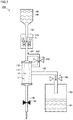
- Fig. 1 is a circuit diagram showing the configuration of a blood purification apparatus according to the first embodiment of the present invention.
- blood purification apparatus 100 according to the first embodiment of the present invention includes a blood purifier 110, a vascular access flow path 120, a cleaning solution flow path 130, and a drainage flow path 150.
- Blood purifier 110 has an inner portion divided, for example, by a semi-permeable membrane 111 such as a hollow fiber membrane into a first portion 10 and a second portion 11.
- a semi-permeable membrane 111 such as a hollow fiber membrane into a first portion 10 and a second portion 11.
- the inside space surrounded by semi-permeable membrane 111 corresponds to first portion 10 while the outside space of semi-permeable membrane 111 corresponds to second portion 11.
- Vascular access flow path 120 is connected to blood purifier 110 and is in communication with first portion 10.
- a puncture needle is provided at an end of vascular access flow path 120 on the side opposite to blood purifier 110.
- Vascular access flow path 120 is provided with a first open-close valve 180 that opens and closes vascular access flow path 120.
- Cleaning solution flow path 130 is connected to blood purifier 110 and is in communication with first portion 10. An end of cleaning solution flow path 130 on the side opposite to blood purifier 110 is connected, for example, to a cleaning solution storage portion 140 in which a cleaning solution 141 made of a physiological saline solution or a dialysis fluid is stored. Cleaning solution flow path 130 is provided with a blood pump 170 capable of bidirectionally feeding a fluid.
- Drainage flow path 150 is connected to blood purifier 110 and is in communication with second portion 11. An end of drainage flow path 150 on the side opposite to blood purifier 110 is connected to a drainage storage portion 160 in which drainage 161 is stored. Drainage flow path 150 is provided with a second open-close valve 190 that opens and closes drainage flow path 150.
- each of blood purifier 110, vascular access flow path 120, cleaning solution flow path 130, and drainage flow path 150 is primed with cleaning solution 141.
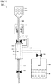
- Fig. 2 is a circuit diagram showing a blood removal process in the blood purification apparatus according to the first embodiment of the present invention.
- blood pump 170 feeds a fluid in the suction direction indicated by an arrow 2 in the state where first open-close valve 180 is opened and second open-close valve 190 is closed.
- first open-close valve 180 is opened
- second open-close valve 190 is closed.
- blood flows from vascular access flow path 120 into first portion 10 of blood purifier 110 as indicated by an arrow 1.
- the blood having passed through first portion 10 of blood purifier 110 flows into cleaning solution flow path 130.
- cleaning solution 141 inside cleaning solution flow path 130 flows into cleaning solution storage portion 140.
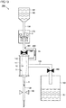
- Fig. 3 is a circuit diagram showing a fluid removal process in the blood purification apparatus according to the first embodiment of the present invention.
- blood pump 170 feeds a fluid in the drainage direction indicated by an arrow 3 in the state where first open-close valve 180 is closed and second open-close valve 190 is opened.
- the blood in cleaning solution flow path 130 flows into first portion 10 of blood purifier 110.
- the blood having flowed into first portion 10 of blood purifier 110 is filtered by semi-permeable membrane 111 with the pressure applied from blood pump 170. Drainage 161 having passed through semi-permeable membrane 111 and reached second portion 11 flows into drainage flow path 150 and is stored in drainage storage portion 160.
- the amount of drainage 161 stored in drainage storage portion 160 is equivalent to the fluid removal amount.
- Fig. 4 is a circuit diagram showing a blood returning process in the blood purification apparatus according to the first embodiment of the present invention.
- blood pump 170 feeds a fluid in the drainage direction in the state where first open-close valve 180 is opened and second open-close valve 190 is closed.
- first open-close valve 180 is opened
- second open-close valve 190 is closed.
- the blood from which a fluid is removed in blood purifier 110 flows into vascular access flow path 120 as indicated by an arrow 5 so as to be returned to a patient.
- the patient may supplementarily receive, together with purified blood, cleaning solution 141 by the amount equivalent to the increased amount of the fluid removal amount.
- the blood removal process and the blood returning process are alternately performed in a simple configuration in which a loop of a blood circuit is not formed. Accordingly, even if a puncture needle is displaced, the amount of blood loss can be suppressed. Specifically, the amount of blood loss can be suppressed to an amount equal to or less than the amount of the blood having flowed into blood purification apparatus 100 in the blood removal process. Furthermore, by inserting a puncture needle only into a vein, blood purification can be performed for a long period of time while relieving the burden on patients.
- the blood purification apparatus according to the second embodiment of the present invention is different from blood purification apparatus 100 according to the first embodiment mainly in that it further includes a branch flow path. Thus, the description of the same configuration as that of blood purification apparatus 100 will not be repeated.
- Fig. 5 is a circuit diagram showing the configuration of a blood purification apparatus according to the second embodiment of the present invention.
- a blood purification apparatus 200 according to the second embodiment of the present invention further includes a branch flow path 230.
- Branch flow path 230 branches from cleaning solution flow path 130 and is connected to blood purifier 110 so as to allow communication between cleaning solution flow path 130 and second portion 11.
- Branch flow path 230 is provided with a third open-close valve 290.
- a branch portion 231 between cleaning solution flow path 130 and branch flow path 230 is provided between blood purifier 110 and blood pump 170.
- each of blood purifier 110, vascular access flow path 120, cleaning solution flow path 130, drainage flow path 150, and branch flow path 230 is primed with cleaning solution 141.
- Fig. 6 is a circuit diagram showing a blood removal process in the blood purification apparatus according to the second embodiment of the present invention.
- blood pump 170 feeds a fluid in the suction direction in the state where first open-close valve 180 is opened, second open-close valve 190 is closed, and third open-close valve 290 is closed.
- first portion 10 of blood purifier 110 As a result, blood flows from vascular access flow path 120 into first portion 10 of blood purifier 110 as indicated by an arrow 1.
- the blood having passed through first portion 10 of blood purifier 110 flows into cleaning solution flow path 130.
- branch portion 231 the blood removal process is ended. In other words, the blood is prevented from flowing into branch flow path 230 in the blood removal process.
- Fig. 7 is a circuit diagram showing the dialysis process in the blood purification apparatus according to the second embodiment of the present invention.
- blood pump 170 feeds a fluid in the drainage direction in the state where first open-close valve 180 is closed, second open-close valve 190 is opened, and third open-close valve 290 is opened.
- the blood in cleaning solution flow path 130 flows into first portion 10 of blood purifier 110.
- Part of cleaning solution 141 in cleaning solution flow path 130 passes through branch flow path 230 as indicated by an arrow 3a and then flows into second portion 11.
- the blood having flowed into first portion 10 of blood purifier 110 comes into contact with cleaning solution 141 in second portion 11 with semi-permeable membrane 111 interposed therebetween. Then, wastes in the blood are moved to second portion 11 by the diffusion principle, so that the blood is purified. Together with the wastes in the blood having passed through semi-permeable membrane 111 and reached second portion 11, cleaning solution 141 having flowed from branch flow path 230 into second portion 11 flows into drainage flow path 150, and then, is stored in drainage storage portion 160.
- Fig. 8 is a circuit diagram showing a fluid removal process in the blood purification apparatus according to the second embodiment of the present invention.
- blood pump 170 feeds a fluid in the drainage direction in the state where first open-close valve 180 is closed, second open-close valve 190 is opened, and third open-close valve 290 is closed.
- the blood in cleaning solution flow path 130 flows into first portion 10 of blood purifier 110.
- the blood having flowed into first portion 10 of blood purifier 110 is filtered by semi-permeable membrane 111 with the pressure applied from blood pump 170. Drainage 161 having passed through semi-permeable membrane 111 and reached second portion 11 flows into drainage flow path 150, and then, is stored in drainage storage portion 160.
- Fig. 9 is a circuit diagram showing a blood returning process in the blood purification apparatus according to the second embodiment of the present invention.
- blood pump 170 feeds a fluid in the drainage direction in the state where first open-close valve 180 is opened, second open-close valve 190 is closed, and third open-close valve 290 is closed.
- the blood purified in blood purifier 110 flows into vascular access flow path 120 as indicated by an arrow 5, so as to be returned to a patient.
- the blood removal process and the blood returning process are alternately performed in a simple configuration in which a loop of a blood circuit is not formed. Accordingly, even if a puncture needle is displaced, the amount of blood loss can be suppressed. Specifically, the amount of blood loss can be suppressed to an amount equal to or less than the amount of the blood having flowed into blood purification apparatus 200 in the blood removal process.
- blood pump 170 may feed a fluid in the drainage direction in the state where first open-close valve 180 is opened, second open-close valve 190 is closed, and third open-close valve 290 is opened.
- the solution located in second portion 11 is reverse-filtered by semi-permeable membrane 111 with the pressure applied from blood pump 170.
- the blood purification apparatus according to the third embodiment of the present invention is different from blood purification apparatus 200 according to the second embodiment mainly in the position where an open-close valve is provided. Thus, the description of the same configuration as that of blood purification apparatus 200 will not be repeated.
- Fig. 10 is a circuit diagram showing the configuration of a blood purification apparatus according to the third embodiment of the present invention.
- a fourth open-close valve 390 is provided in place of third open-close valve 290.
- Fourth open-close valve 390 is provided in a portion of cleaning solution flow path 130, the portion being located between blood purifier 110 and branch portion 231 that is located between cleaning solution flow path 130 and branch flow path 230. It should be noted that both third open-close valve 290 and fourth open-close valve 390 may be provided.
- each of blood purifier 110, vascular access flow path 120, cleaning solution flow path 130, drainage flow path 150, and branch flow path 230 is primed with cleaning solution 141.
- Fig. 11 is a circuit diagram showing a blood removal process in the blood purification apparatus according to the third embodiment of the present invention.
- blood pump 170 feeds a fluid in the suction direction in the state where first open-close valve 180 is opened, second open-close valve 190 is closed, and fourth open-close valve 390 is opened.
- first portion 10 of blood purifier 110 flows into first portion 10 of blood purifier 110 from vascular access flow path 120 as indicated by an arrow 1.
- the blood having passed through first portion 10 of blood purifier 110 flows into cleaning solution flow path 130.
- the blood removal process is ended before the blood reaches branch portion 231. In other words, the blood is prevented from flowing into branch flow path 230 in the blood removal process.
- Fig. 12 is a circuit diagram showing a fluid removal process in the blood purification apparatus according to the third embodiment of the present invention.
- blood pump 170 feeds a fluid in the drainage direction in the state where first open-close valve 180 is closed, second open-close valve 190 is opened, and fourth open-close valve 390 is opened.
- the blood in cleaning solution flow path 130 flows into first portion 10 of blood purifier 110.
- the blood having flowed into first portion 10 of blood purifier 110 is filtered by semi-permeable membrane 111 with the pressure applied from blood pump 170. Drainage 161 having passed through semi-permeable membrane 111 and reached second portion 11 flows into drainage flow path 150, and then, is stored in drainage storage portion 160.
- Fig. 13 is a circuit diagram showing a blood returning process in the blood purification apparatus according to the third embodiment of the present invention.
- blood pump 170 feeds a fluid in the drainage direction in the state where first open-close valve 180 is opened, second open-close valve 190 is closed, and fourth open-close valve 390 is closed.
- the solution located in second portion 11 is reverse-filtered by semi-permeable membrane 111 with the pressure applied from blood pump 170.
- the blood purified in blood purifier 110 flows into vascular access flow path 120 as indicated by an arrow 5 so as to be returned to a patient.
- the blood removal process and the blood returning process are alternately performed in a simple configuration in which a loop of a blood circuit is not formed. Accordingly, even if a puncture needle is displaced, the amount of blood loss can be suppressed. Specifically, the amount of blood loss can be suppressed to an amount equal to or less than the amount of the blood having flowed into blood purification apparatus 300 in the blood removal process.
Landscapes
- Health & Medical Sciences (AREA)
- Heart & Thoracic Surgery (AREA)
- Urology & Nephrology (AREA)
- Hematology (AREA)
- Anesthesiology (AREA)
- Biomedical Technology (AREA)
- Engineering & Computer Science (AREA)
- Life Sciences & Earth Sciences (AREA)
- Animal Behavior & Ethology (AREA)
- General Health & Medical Sciences (AREA)
- Public Health (AREA)
- Veterinary Medicine (AREA)
- Vascular Medicine (AREA)
- Emergency Medicine (AREA)
- External Artificial Organs (AREA)
Abstract
Description
- The present invention relates to a blood purification apparatus.
- As a prior art document, Japanese Patent Laying-Open No.
2007-20990 PTL 1 includes a dialyzer, a blood circuit, a blood pump, a dialysis fluid circuit, and an ultrasonic-type blood flow meter. - PTL 1: Japanese Patent Laying-Open No.
2007-20990 - Similarly to the configuration of a commonly used blood purification apparatus, the blood circuit of the hemodialysis apparatus disclosed in
PTL 1 is formed of an artery-side blood circuit on the upstream side of the dialyzer and a vein-side blood circuit on the downstream side of the dialyzer so as to form a loop. - In general, a blood purification apparatus is installed in a hospital room narrower than a dialysis room. Thus, such a blood purification apparatus is required to have a simplified apparatus configuration. In the case of a blood purification apparatus in which the above-described loop is formed, needles need to be inserted into each of an artery and a vein, which may increase the burden on patients and medical workers. Also, displacement of a puncture needle may increase the amount of blood loss.
- The present invention has been made in light of the above-described problems. An object of the present invention is to provide a blood purification apparatus that has a simplified configuration while still allowing suppression of the amount of blood lost in the case of displacement of a puncture needle.
- A blood purification apparatus according to the present invention includes a blood purifier, a vascular access flow path, a cleaning solution flow path, and a drainage flow path. The blood purifier has an inner portion divided by a semi-permeable membrane into a first portion and a second portion. The vascular access flow path is connected to the blood purifier and is in communication with the first portion. The cleaning solution flow path is connected to the blood purifier and is in communication with the first portion. The drainage flow path is connected to the blood purifier and is in communication with the second portion. The cleaning solution flow path is provided with a blood pump capable of bidirectionally feeding a fluid. An open-close valve is provided in each of the vascular access flow path and the drainage flow path.
- In an embodiment of the present invention, the blood purification apparatus further includes a branch flow path. The branch flow path branches from the cleaning solution flow path and is connected to the blood purifier to allow communication between the cleaning solution flow path and the second portion. An open-close valve is provided in the branch flow path.
- In an embodiment of the present invention, the blood purification apparatus further includes a branch flow path. The branch flow path branches from the cleaning solution flow path and is connected to the blood purifier to allow communication between the cleaning solution flow path and the second portion. An open-close valve is provided in a portion of the cleaning solution flow path, the portion being located between the blood purifier and a branch portion that is located between the cleaning solution flow path and the branch flow path.
- According to the present invention, the amount of blood lost in the case of displacement of a puncture needle can be suppressed while simplifying the configuration of the blood purification apparatus.
-
-
Fig. 1 is a circuit diagram showing the configuration of a blood purification apparatus according to the first embodiment of the present invention. -
Fig. 2 is a circuit diagram showing a blood removal process in the blood purification apparatus according to the first embodiment of the present invention. -
Fig. 3 is a circuit diagram showing a fluid removal process in the blood purification apparatus according to the first embodiment of the present invention. -
Fig. 4 is a circuit diagram showing a blood returning process in the blood purification apparatus according to the first embodiment of the present invention. -
Fig. 5 is a circuit diagram showing the configuration of a blood purification apparatus according to the second embodiment of the present invention. -
Fig. 6 is a circuit diagram showing a blood removal process in the blood purification apparatus according to the second embodiment of the present invention. -
Fig. 7 is a circuit diagram showing a dialysis process in the blood purification apparatus according to the second embodiment of the present invention. -
Fig. 8 is a circuit diagram showing a fluid removal process in the blood purification apparatus according to the second embodiment of the present invention. -
Fig. 9 is a circuit diagram showing a blood returning process in the blood purification apparatus according to the second embodiment of the present invention. -
Fig. 10 is a circuit diagram showing the configuration of a blood purification apparatus according to the third embodiment of the present invention. -
Fig. 11 is a circuit diagram showing a blood removal process in the blood purification apparatus according to the third embodiment of the present invention. -
Fig. 12 is a circuit diagram showing a fluid removal process in the blood purification apparatus according to the third embodiment of the present invention. -
Fig. 13 is a circuit diagram showing a blood returning process in the blood purification apparatus according to the third embodiment of the present invention. - In the following, a blood purification apparatus according to each of embodiments of the present invention will be described with reference to the accompanying drawings. In the following description of the embodiments, the same or corresponding components will be denoted by the same reference characters, and description thereof will not be repeated.
-
Fig. 1 is a circuit diagram showing the configuration of a blood purification apparatus according to the first embodiment of the present invention. As shown inFig. 1 ,blood purification apparatus 100 according to the first embodiment of the present invention includes ablood purifier 110, a vascularaccess flow path 120, a cleaningsolution flow path 130, and adrainage flow path 150. -
Blood purifier 110 has an inner portion divided, for example, by asemi-permeable membrane 111 such as a hollow fiber membrane into afirst portion 10 and asecond portion 11. In the present embodiment, the inside space surrounded bysemi-permeable membrane 111 corresponds tofirst portion 10 while the outside space ofsemi-permeable membrane 111 corresponds tosecond portion 11. - Vascular
access flow path 120 is connected toblood purifier 110 and is in communication withfirst portion 10. A puncture needle is provided at an end of vascularaccess flow path 120 on the side opposite toblood purifier 110. Vascularaccess flow path 120 is provided with a first open-close valve 180 that opens and closes vascularaccess flow path 120. - Cleaning
solution flow path 130 is connected toblood purifier 110 and is in communication withfirst portion 10. An end of cleaningsolution flow path 130 on the side opposite toblood purifier 110 is connected, for example, to a cleaningsolution storage portion 140 in which acleaning solution 141 made of a physiological saline solution or a dialysis fluid is stored. Cleaningsolution flow path 130 is provided with ablood pump 170 capable of bidirectionally feeding a fluid. -
Drainage flow path 150 is connected toblood purifier 110 and is in communication withsecond portion 11. An end ofdrainage flow path 150 on the side opposite toblood purifier 110 is connected to adrainage storage portion 160 in whichdrainage 161 is stored.Drainage flow path 150 is provided with a second open-close valve 190 that opens and closesdrainage flow path 150. - In the following, the operation of
blood purification apparatus 100 according to the first embodiment of the present invention will be described. - Before starting dialysis by
blood purification apparatus 100, each ofblood purifier 110, vascularaccess flow path 120, cleaningsolution flow path 130, anddrainage flow path 150 is primed withcleaning solution 141. -
Fig. 2 is a circuit diagram showing a blood removal process in the blood purification apparatus according to the first embodiment of the present invention. As shown inFig. 2 , in the blood removal process inblood purification apparatus 100 according to the first embodiment of the present invention,blood pump 170 feeds a fluid in the suction direction indicated by anarrow 2 in the state where first open-close valve 180 is opened and second open-close valve 190 is closed. As a result, blood flows from vascularaccess flow path 120 intofirst portion 10 ofblood purifier 110 as indicated by anarrow 1. The blood having passed throughfirst portion 10 ofblood purifier 110 flows into cleaningsolution flow path 130. In accordance with the amount of the blood having flowed into cleaningsolution flow path 130,cleaning solution 141 inside cleaningsolution flow path 130 flows into cleaningsolution storage portion 140. -
Fig. 3 is a circuit diagram showing a fluid removal process in the blood purification apparatus according to the first embodiment of the present invention. As shown inFig. 3 , in the fluid removal process inblood purification apparatus 100 according to the first embodiment of the present invention,blood pump 170 feeds a fluid in the drainage direction indicated by anarrow 3 in the state where first open-close valve 180 is closed and second open-close valve 190 is opened. - As a result, the blood in cleaning
solution flow path 130 flows intofirst portion 10 ofblood purifier 110. The blood having flowed intofirst portion 10 ofblood purifier 110 is filtered bysemi-permeable membrane 111 with the pressure applied fromblood pump 170.Drainage 161 having passed throughsemi-permeable membrane 111 and reachedsecond portion 11 flows intodrainage flow path 150 and is stored indrainage storage portion 160. The amount ofdrainage 161 stored indrainage storage portion 160 is equivalent to the fluid removal amount. -
Fig. 4 is a circuit diagram showing a blood returning process in the blood purification apparatus according to the first embodiment of the present invention. As shown inFig. 4 , in the blood returning process inblood purification apparatus 100 according to the first embodiment of the present invention,blood pump 170 feeds a fluid in the drainage direction in the state where first open-close valve 180 is opened and second open-close valve 190 is closed. As a result, the blood from which a fluid is removed inblood purifier 110 flows into vascularaccess flow path 120 as indicated by anarrow 5 so as to be returned to a patient. - When the fluid removal amount is intentionally increased in the fluid removal process, then in the blood returning process, the patient may supplementarily receive, together with purified blood,
cleaning solution 141 by the amount equivalent to the increased amount of the fluid removal amount. - In
blood purification apparatus 100 according to the first embodiment of the present invention, the blood removal process and the blood returning process are alternately performed in a simple configuration in which a loop of a blood circuit is not formed. Accordingly, even if a puncture needle is displaced, the amount of blood loss can be suppressed. Specifically, the amount of blood loss can be suppressed to an amount equal to or less than the amount of the blood having flowed intoblood purification apparatus 100 in the blood removal process. Furthermore, by inserting a puncture needle only into a vein, blood purification can be performed for a long period of time while relieving the burden on patients. - In the following, a blood purification apparatus according to the second embodiment of the present invention will be described with reference to the accompanying drawings. The blood purification apparatus according to the second embodiment of the present invention is different from
blood purification apparatus 100 according to the first embodiment mainly in that it further includes a branch flow path. Thus, the description of the same configuration as that ofblood purification apparatus 100 will not be repeated. -
Fig. 5 is a circuit diagram showing the configuration of a blood purification apparatus according to the second embodiment of the present invention. As shown inFig. 5 , ablood purification apparatus 200 according to the second embodiment of the present invention further includes abranch flow path 230.Branch flow path 230 branches from cleaningsolution flow path 130 and is connected toblood purifier 110 so as to allow communication between cleaningsolution flow path 130 andsecond portion 11.Branch flow path 230 is provided with a third open-close valve 290. Abranch portion 231 between cleaningsolution flow path 130 andbranch flow path 230 is provided betweenblood purifier 110 andblood pump 170. - In the following, the operation of
blood purification apparatus 200 according to the second embodiment of the present invention will be described. - Before starting dialysis by
blood purification apparatus 200, each ofblood purifier 110, vascularaccess flow path 120, cleaningsolution flow path 130,drainage flow path 150, andbranch flow path 230 is primed withcleaning solution 141. -
Fig. 6 is a circuit diagram showing a blood removal process in the blood purification apparatus according to the second embodiment of the present invention. As shown inFig. 6 , in the blood removal process inblood purification apparatus 200 according to the second embodiment of the present invention,blood pump 170 feeds a fluid in the suction direction in the state where first open-close valve 180 is opened, second open-close valve 190 is closed, and third open-close valve 290 is closed. - As a result, blood flows from vascular
access flow path 120 intofirst portion 10 ofblood purifier 110 as indicated by anarrow 1. The blood having passed throughfirst portion 10 ofblood purifier 110 flows into cleaningsolution flow path 130. Before the blood reachesbranch portion 231, the blood removal process is ended. In other words, the blood is prevented from flowing intobranch flow path 230 in the blood removal process. -
Fig. 7 is a circuit diagram showing the dialysis process in the blood purification apparatus according to the second embodiment of the present invention. As shown inFig. 7 , in the dialysis process inblood purification apparatus 200 according to the second embodiment of the present invention,blood pump 170 feeds a fluid in the drainage direction in the state where first open-close valve 180 is closed, second open-close valve 190 is opened, and third open-close valve 290 is opened. - As a result, the blood in cleaning
solution flow path 130 flows intofirst portion 10 ofblood purifier 110. Part ofcleaning solution 141 in cleaningsolution flow path 130 passes throughbranch flow path 230 as indicated by anarrow 3a and then flows intosecond portion 11. - The blood having flowed into
first portion 10 ofblood purifier 110 comes into contact withcleaning solution 141 insecond portion 11 withsemi-permeable membrane 111 interposed therebetween. Then, wastes in the blood are moved tosecond portion 11 by the diffusion principle, so that the blood is purified. Together with the wastes in the blood having passed throughsemi-permeable membrane 111 and reachedsecond portion 11,cleaning solution 141 having flowed frombranch flow path 230 intosecond portion 11 flows intodrainage flow path 150, and then, is stored indrainage storage portion 160. -
Fig. 8 is a circuit diagram showing a fluid removal process in the blood purification apparatus according to the second embodiment of the present invention. As shown inFig. 8 , in the fluid removal process inblood purification apparatus 200 according to the second embodiment of the present invention,blood pump 170 feeds a fluid in the drainage direction in the state where first open-close valve 180 is closed, second open-close valve 190 is opened, and third open-close valve 290 is closed. - As a result, the blood in cleaning
solution flow path 130 flows intofirst portion 10 ofblood purifier 110. The blood having flowed intofirst portion 10 ofblood purifier 110 is filtered bysemi-permeable membrane 111 with the pressure applied fromblood pump 170.Drainage 161 having passed throughsemi-permeable membrane 111 and reachedsecond portion 11 flows intodrainage flow path 150, and then, is stored indrainage storage portion 160. -
Fig. 9 is a circuit diagram showing a blood returning process in the blood purification apparatus according to the second embodiment of the present invention. As shown inFig. 9 , in the blood returning process inblood purification apparatus 200 according to the second embodiment of the present invention,blood pump 170 feeds a fluid in the drainage direction in the state where first open-close valve 180 is opened, second open-close valve 190 is closed, and third open-close valve 290 is closed. As a result, the blood purified inblood purifier 110 flows into vascularaccess flow path 120 as indicated by anarrow 5, so as to be returned to a patient. - Also in
blood purification apparatus 200 according to the second embodiment of the present invention, the blood removal process and the blood returning process are alternately performed in a simple configuration in which a loop of a blood circuit is not formed. Accordingly, even if a puncture needle is displaced, the amount of blood loss can be suppressed. Specifically, the amount of blood loss can be suppressed to an amount equal to or less than the amount of the blood having flowed intoblood purification apparatus 200 in the blood removal process. - Also, in the blood returning process,
blood pump 170 may feed a fluid in the drainage direction in the state where first open-close valve 180 is opened, second open-close valve 190 is closed, and third open-close valve 290 is opened. In this case, the solution located insecond portion 11 is reverse-filtered bysemi-permeable membrane 111 with the pressure applied fromblood pump 170. - In the following, a blood purification apparatus according to the third embodiment of the present invention will be described with reference to the accompanying drawings. The blood purification apparatus according to the third embodiment of the present invention is different from
blood purification apparatus 200 according to the second embodiment mainly in the position where an open-close valve is provided. Thus, the description of the same configuration as that ofblood purification apparatus 200 will not be repeated. -
Fig. 10 is a circuit diagram showing the configuration of a blood purification apparatus according to the third embodiment of the present invention. As shown inFig. 10 , in ablood purification apparatus 300 according to the third embodiment of the present invention, a fourth open-close valve 390 is provided in place of third open-close valve 290. Fourth open-close valve 390 is provided in a portion of cleaningsolution flow path 130, the portion being located betweenblood purifier 110 andbranch portion 231 that is located between cleaningsolution flow path 130 andbranch flow path 230. It should be noted that both third open-close valve 290 and fourth open-close valve 390 may be provided. - In the following, the operation of
blood purification apparatus 300 according to the third embodiment of the present invention will be described. - Before starting dialysis by
blood purification apparatus 300, each ofblood purifier 110, vascularaccess flow path 120, cleaningsolution flow path 130,drainage flow path 150, andbranch flow path 230 is primed withcleaning solution 141. -
Fig. 11 is a circuit diagram showing a blood removal process in the blood purification apparatus according to the third embodiment of the present invention. As shown inFig. 11 , in the blood removal process inblood purification apparatus 300 according to the third embodiment of the present invention,blood pump 170 feeds a fluid in the suction direction in the state where first open-close valve 180 is opened, second open-close valve 190 is closed, and fourth open-close valve 390 is opened. - As a result, blood flows into
first portion 10 ofblood purifier 110 from vascularaccess flow path 120 as indicated by anarrow 1. The blood having passed throughfirst portion 10 ofblood purifier 110 flows into cleaningsolution flow path 130. It should be noted that the blood removal process is ended before the blood reachesbranch portion 231. In other words, the blood is prevented from flowing intobranch flow path 230 in the blood removal process. -
Fig. 12 is a circuit diagram showing a fluid removal process in the blood purification apparatus according to the third embodiment of the present invention. As shown inFig. 12 , in the fluid removal process inblood purification apparatus 300 according to the third embodiment of the present invention,blood pump 170 feeds a fluid in the drainage direction in the state where first open-close valve 180 is closed, second open-close valve 190 is opened, and fourth open-close valve 390 is opened. - As a result, the blood in cleaning
solution flow path 130 flows intofirst portion 10 ofblood purifier 110. The blood having flowed intofirst portion 10 ofblood purifier 110 is filtered bysemi-permeable membrane 111 with the pressure applied fromblood pump 170.Drainage 161 having passed throughsemi-permeable membrane 111 and reachedsecond portion 11 flows intodrainage flow path 150, and then, is stored indrainage storage portion 160. -
Fig. 13 is a circuit diagram showing a blood returning process in the blood purification apparatus according to the third embodiment of the present invention. As shown inFig. 13 , in the blood returning process inblood purification apparatus 300 according to the third embodiment of the present invention,blood pump 170 feeds a fluid in the drainage direction in the state where first open-close valve 180 is opened, second open-close valve 190 is closed, and fourth open-close valve 390 is closed. As a result, the solution located insecond portion 11 is reverse-filtered bysemi-permeable membrane 111 with the pressure applied fromblood pump 170. Also, the blood purified inblood purifier 110 flows into vascularaccess flow path 120 as indicated by anarrow 5 so as to be returned to a patient. - Also in
blood purification apparatus 300 according to the third embodiment of the present invention, the blood removal process and the blood returning process are alternately performed in a simple configuration in which a loop of a blood circuit is not formed. Accordingly, even if a puncture needle is displaced, the amount of blood loss can be suppressed. Specifically, the amount of blood loss can be suppressed to an amount equal to or less than the amount of the blood having flowed intoblood purification apparatus 300 in the blood removal process. - It is noted that the embodiments disclosed herein are illustrative in every respect, and do not provide grounds for restrictive interpretation. Therefore, the technical scope of the present invention should not be interpreted by the above embodiments only, and is defined based on the description in the scope of the claims. Further, any modifications within the meaning and scope equivalent to the scope of the claims are encompassed.
- 10 first portion, 11 second portion, 100, 200, 300 blood purification apparatus, 110 blood purifier, 111 semi-permeable membrane, 120 vascular access flow path, 130 cleaning solution flow path, 140 cleaning solution storage portion, 141 cleaning solution, 150 drainage flow path, 160 drainage storage portion, 161 drainage, 170 blood pump, 180 first open-close valve, 190 second open-close valve, 230 branch flow path, 231 branch portion, 290 third open-close valve, 390 fourth open-close valve.
Claims (3)
- A blood purification apparatus comprising:a blood purifier that has an inner portion divided by a semi-permeable membrane into a first portion and a second portion;a vascular access flow path that is connected to the blood purifier and is in communication with the first portion;a cleaning solution flow path that is connected to the blood purifier and is in communication with the first portion; anda drainage flow path that is connected to the blood purifier and is in communication with the second portion, whereinthe cleaning solution flow path is provided with a blood pump capable of bidirectionally feeding a fluid, andan open-close valve is provided in each of the vascular access flow path and the drainage flow path.
- The blood purification apparatus according to claim 1, further comprising a branch flow path that branches from the cleaning solution flow path and is connected to the blood purifier to allow communication between the cleaning solution flow path and the second portion, wherein
an open-close valve is provided in the branch flow path. - The blood purification apparatus according to claim 1, further comprising a branch flow path that branches from the cleaning solution flow path and is connected to the blood purifier to allow communication between the cleaning solution flow path and the second portion, wherein
an open-close valve is provided in a portion of the cleaning solution flow path, the portion being located between the blood purifier and a branch portion that is located between the cleaning solution flow path and the branch flow path.
Applications Claiming Priority (2)
| Application Number | Priority Date | Filing Date | Title |
|---|---|---|---|
| JP2017122209 | 2017-06-22 | ||
| PCT/JP2018/023907 WO2018235963A1 (en) | 2017-06-22 | 2018-06-22 | Blood purification device |
Publications (2)
| Publication Number | Publication Date |
|---|---|
| EP3643341A1 true EP3643341A1 (en) | 2020-04-29 |
| EP3643341A4 EP3643341A4 (en) | 2021-03-10 |
Family
ID=64736024
Family Applications (1)
| Application Number | Title | Priority Date | Filing Date |
|---|---|---|---|
| EP18819603.4A Withdrawn EP3643341A4 (en) | 2017-06-22 | 2018-06-22 | BLOOD PURIFICATION DEVICE |
Country Status (5)
| Country | Link |
|---|---|
| US (1) | US11628241B2 (en) |
| EP (1) | EP3643341A4 (en) |
| JP (1) | JP7192768B2 (en) |
| CN (1) | CN110891628B (en) |
| WO (1) | WO2018235963A1 (en) |
Families Citing this family (1)
| Publication number | Priority date | Publication date | Assignee | Title |
|---|---|---|---|---|
| TWI860561B (en) * | 2022-10-20 | 2024-11-01 | 佳世達科技股份有限公司 | Hemodialysis device |
Family Cites Families (14)
| Publication number | Priority date | Publication date | Assignee | Title |
|---|---|---|---|---|
| FR2519555A1 (en) | 1982-01-11 | 1983-07-18 | Rhone Poulenc Sa | APPARATUS AND METHOD FOR ALTERNATIVE PLASMAPHERESE WITH MEMBRANE APPARATUS |
| FR2548541B1 (en) * | 1983-07-07 | 1986-09-12 | Rhone Poulenc Sa | PLASMAPHERESE PROCESS AND APPARATUS FOR USE IN PARTICULAR FOR THIS PROCESS |
| JPS6260562A (en) | 1985-09-10 | 1987-03-17 | 株式会社 ニツシヨ− | Method for detecting breakage of hollow yarn separator for plasma sampler |
| JP2503019B2 (en) * | 1987-07-07 | 1996-06-05 | 株式会社クラレ | Plasma collection device |
| GB8724914D0 (en) * | 1987-10-23 | 1987-11-25 | Research Corp Ltd | Blood purification apparatus |
| US4954128A (en) | 1988-08-23 | 1990-09-04 | Baxter International Inc. | Therapeutics plasma exchange system |
| IT1244805B (en) | 1990-11-22 | 1994-09-05 | Roerig Farmaceutici Italiana S | SINGLE NEEDLE PLASMAFERESIS EXTRA-BODY CIRCUIT |
| JP4325594B2 (en) | 2005-07-20 | 2009-09-02 | ニプロ株式会社 | Hemodialysis machine |
| AU2008357106B2 (en) | 2008-05-26 | 2013-02-07 | Gambro Lundia Ab | A hemodialysis or hemo(dia)filtration apparatus and a method for controlling a hemodialysis or hemo(dia)filtration apparatus |
| DE102010020838A1 (en) * | 2010-05-18 | 2011-11-24 | Fresenius Medical Care Deutschland Gmbh | Valve assembly for use in extracorporeal blood circulation and method |
| CN102971023B (en) * | 2010-07-05 | 2016-06-15 | 甘布罗伦迪亚股份公司 | Ambulatory ultrafiltration device |
| CN102500005B (en) * | 2011-09-30 | 2015-04-22 | 中南大学 | Blood transfusion system for autologous blood recovery, filtration and purification |
| DE102013006562A1 (en) | 2013-04-16 | 2014-10-16 | Fresenius Medical Care Deutschland Gmbh | Method for determining the pressure in an extracorporeal circuit |
| EP3142723B1 (en) * | 2014-05-13 | 2018-07-04 | Monica Zanotti | Single needle hemo(dia)filtration apparatus |
-
2018
- 2018-06-22 US US16/624,944 patent/US11628241B2/en active Active
- 2018-06-22 WO PCT/JP2018/023907 patent/WO2018235963A1/en not_active Ceased
- 2018-06-22 CN CN201880041650.7A patent/CN110891628B/en active Active
- 2018-06-22 EP EP18819603.4A patent/EP3643341A4/en not_active Withdrawn
- 2018-06-22 JP JP2019525718A patent/JP7192768B2/en active Active
Also Published As
| Publication number | Publication date |
|---|---|
| CN110891628B (en) | 2023-02-21 |
| CN110891628A (en) | 2020-03-17 |
| WO2018235963A1 (en) | 2018-12-27 |
| JP7192768B2 (en) | 2022-12-20 |
| US11628241B2 (en) | 2023-04-18 |
| JPWO2018235963A1 (en) | 2020-04-23 |
| US20200139035A1 (en) | 2020-05-07 |
| EP3643341A4 (en) | 2021-03-10 |
Similar Documents
| Publication | Publication Date | Title |
|---|---|---|
| US5895368A (en) | Blood set priming method and apparatus | |
| CN1874803B (en) | Circuit for extracorporeal blood treatment and flow-reversing device used therein | |
| EP2883566B1 (en) | Extracorporeal blood treatment system and valve unit for pre/post infusion | |
| JP5588692B2 (en) | Dialysis machine | |
| KR950700095A (en) | ORGAN SUPPORT SYSTEM | |
| WO2008051391A2 (en) | Vascular conduit | |
| US20140100508A1 (en) | Hybrid arteriovenous shunt | |
| US20150059894A1 (en) | Method for removing blood from an extracorporeal blood circuit as well as apparatuses | |
| US8915892B2 (en) | T-piece for creating turbulence | |
| EP3409306A1 (en) | Blood purification device | |
| US20170043086A1 (en) | Enhanced cannulation method and needles | |
| US11628241B2 (en) | Blood purification apparatus | |
| US8221388B2 (en) | Biased clamping assemblies | |
| DK3088020T3 (en) | BLOOD HOSE KIT FOR DIALYSIS AND METHOD OF USE | |
| US20210030938A1 (en) | A blood hose set, a control device or closed-loop control device, a blood treatment apparatus and a method for the single-needle treatment | |
| JP2001353215A (en) | Medical Flexible Tube Clamping Device | |
| US11918772B2 (en) | Fluid sampling or infusion device for an extracorporeal blood treatment apparatus | |
| EP3195890B1 (en) | Blood purification device | |
| US20260021232A1 (en) | Syringe-free blood return | |
| CN219595457U (en) | Remaining needle convenient for blood drawing | |
| EP3714919A1 (en) | Reinfusion tube system, package and methods | |
| JP4754049B2 (en) | Medical flexible tube clamping device | |
| WO2024007921A1 (en) | Implantable access device and fluid circulation system | |
| JP3123865U (en) | Extracorporeal circuit | |
| CN209137531U (en) | Dialysis blood back pipeline and dialysis system |
Legal Events
| Date | Code | Title | Description |
|---|---|---|---|
| STAA | Information on the status of an ep patent application or granted ep patent |
Free format text: STATUS: THE INTERNATIONAL PUBLICATION HAS BEEN MADE |
|
| PUAI | Public reference made under article 153(3) epc to a published international application that has entered the european phase |
Free format text: ORIGINAL CODE: 0009012 |
|
| STAA | Information on the status of an ep patent application or granted ep patent |
Free format text: STATUS: REQUEST FOR EXAMINATION WAS MADE |
|
| 17P | Request for examination filed |
Effective date: 20191220 |
|
| AK | Designated contracting states |
Kind code of ref document: A1 Designated state(s): AL AT BE BG CH CY CZ DE DK EE ES FI FR GB GR HR HU IE IS IT LI LT LU LV MC MK MT NL NO PL PT RO RS SE SI SK SM TR |
|
| AX | Request for extension of the european patent |
Extension state: BA ME |
|
| DAV | Request for validation of the european patent (deleted) | ||
| DAX | Request for extension of the european patent (deleted) | ||
| A4 | Supplementary search report drawn up and despatched |
Effective date: 20210208 |
|
| RIC1 | Information provided on ipc code assigned before grant |
Ipc: A61M 1/16 20060101ALI20210202BHEP Ipc: A61M 1/30 20060101AFI20210202BHEP Ipc: A61M 1/34 20060101ALI20210202BHEP |
|
| STAA | Information on the status of an ep patent application or granted ep patent |
Free format text: STATUS: EXAMINATION IS IN PROGRESS |
|
| 17Q | First examination report despatched |
Effective date: 20220929 |
|
| GRAP | Despatch of communication of intention to grant a patent |
Free format text: ORIGINAL CODE: EPIDOSNIGR1 |
|
| STAA | Information on the status of an ep patent application or granted ep patent |
Free format text: STATUS: GRANT OF PATENT IS INTENDED |
|
| INTG | Intention to grant announced |
Effective date: 20241014 |
|
| STAA | Information on the status of an ep patent application or granted ep patent |
Free format text: STATUS: THE APPLICATION IS DEEMED TO BE WITHDRAWN |
|
| 18D | Application deemed to be withdrawn |
Effective date: 20250215 |