EP3643253A1 - Clipping tool - Google Patents
Clipping tool Download PDFInfo
- Publication number
- EP3643253A1 EP3643253A1 EP18820282.4A EP18820282A EP3643253A1 EP 3643253 A1 EP3643253 A1 EP 3643253A1 EP 18820282 A EP18820282 A EP 18820282A EP 3643253 A1 EP3643253 A1 EP 3643253A1
- Authority
- EP
- European Patent Office
- Prior art keywords
- end side
- distal end
- proximal end
- tightening ring
- arm portions
- Prior art date
- Legal status (The legal status is an assumption and is not a legal conclusion. Google has not performed a legal analysis and makes no representation as to the accuracy of the status listed.)
- Granted
Links
Images




Classifications
-
- A—HUMAN NECESSITIES
- A61—MEDICAL OR VETERINARY SCIENCE; HYGIENE
- A61B—DIAGNOSIS; SURGERY; IDENTIFICATION
- A61B17/00—Surgical instruments, devices or methods
- A61B17/12—Surgical instruments, devices or methods for ligaturing or otherwise compressing tubular parts of the body, e.g. blood vessels or umbilical cord
- A61B17/122—Clamps or clips, e.g. for the umbilical cord
-
- A—HUMAN NECESSITIES
- A61—MEDICAL OR VETERINARY SCIENCE; HYGIENE
- A61B—DIAGNOSIS; SURGERY; IDENTIFICATION
- A61B17/00—Surgical instruments, devices or methods
- A61B17/12—Surgical instruments, devices or methods for ligaturing or otherwise compressing tubular parts of the body, e.g. blood vessels or umbilical cord
- A61B17/128—Surgical instruments, devices or methods for ligaturing or otherwise compressing tubular parts of the body, e.g. blood vessels or umbilical cord for applying or removing clamps or clips
- A61B17/1285—Surgical instruments, devices or methods for ligaturing or otherwise compressing tubular parts of the body, e.g. blood vessels or umbilical cord for applying or removing clamps or clips for minimally invasive surgery
-
- A—HUMAN NECESSITIES
- A61—MEDICAL OR VETERINARY SCIENCE; HYGIENE
- A61B—DIAGNOSIS; SURGERY; IDENTIFICATION
- A61B17/00—Surgical instruments, devices or methods
- A61B17/08—Wound clamps or clips, i.e. not or only partly penetrating the tissue ; Devices for bringing together the edges of a wound
- A61B17/083—Clips, e.g. resilient
-
- A—HUMAN NECESSITIES
- A61—MEDICAL OR VETERINARY SCIENCE; HYGIENE
- A61B—DIAGNOSIS; SURGERY; IDENTIFICATION
- A61B17/00—Surgical instruments, devices or methods
- A61B17/10—Surgical instruments, devices or methods for applying or removing wound clamps, e.g. containing only one clamp or staple; Wound clamp magazines
-
- A—HUMAN NECESSITIES
- A61—MEDICAL OR VETERINARY SCIENCE; HYGIENE
- A61B—DIAGNOSIS; SURGERY; IDENTIFICATION
- A61B17/00—Surgical instruments, devices or methods
- A61B17/12—Surgical instruments, devices or methods for ligaturing or otherwise compressing tubular parts of the body, e.g. blood vessels or umbilical cord
- A61B17/122—Clamps or clips, e.g. for the umbilical cord
- A61B17/1227—Spring clips
-
- A—HUMAN NECESSITIES
- A61—MEDICAL OR VETERINARY SCIENCE; HYGIENE
- A61B—DIAGNOSIS; SURGERY; IDENTIFICATION
- A61B17/00—Surgical instruments, devices or methods
- A61B17/12—Surgical instruments, devices or methods for ligaturing or otherwise compressing tubular parts of the body, e.g. blood vessels or umbilical cord
- A61B17/128—Surgical instruments, devices or methods for ligaturing or otherwise compressing tubular parts of the body, e.g. blood vessels or umbilical cord for applying or removing clamps or clips
-
- A—HUMAN NECESSITIES
- A61—MEDICAL OR VETERINARY SCIENCE; HYGIENE
- A61B—DIAGNOSIS; SURGERY; IDENTIFICATION
- A61B17/00—Surgical instruments, devices or methods
- A61B17/12—Surgical instruments, devices or methods for ligaturing or otherwise compressing tubular parts of the body, e.g. blood vessels or umbilical cord
- A61B2017/12004—Surgical instruments, devices or methods for ligaturing or otherwise compressing tubular parts of the body, e.g. blood vessels or umbilical cord for haemostasis, for prevention of bleeding
Definitions
- the present invention relates to a clip treatment tool for an endoscope, which is used, for example, to close a wound and to stop bleeding in a living body.
- a clip treatment tool for an endoscope is used, for example, to close a wound and to stop bleeding by extruding arm portions of a clip from a distal end of the endoscope, which is inserted into a living body, and by ligating a treatment part, such as the wound and the bleeding part, with distal end parts of the arm portions of the clip.
- Examples of such a clip treatment tool known to date include clip treatment tools that can freely open and close arm portions of a clip (see JP5750619B , JP4921173B , US9339270B , US2016/0367258A , and JP2008-289524A ).
- clip treatment tools that can freely open and close arm portions of a clip (see JP5750619B , JP4921173B , US9339270B , US2016/0367258A , and JP2008-289524A ).
- the clip is placed in the body of the patient. Therefore, when the clip is placed in the body at a position displaced from a target position to be ligated due to an erroneous operation or the like, and when, for example, the clip placed in the body becomes unnecessary after the objective of using the clip, such as stoppage of bleeding, has been sufficiently achieved, the clip remains placed in the living body, and it is necessary to wait until the clip is naturally removed due to a change in body tissue of the patient. That is, there is a problem in that it is not possible to remove the clip at a desirable timing.
- An object of the present invention is to provide a clip treatment tool with which, after the clip has been once applied, it is possible to reliably maintain the applied state, and it is possible to remove a clip placed in a living body at any desirable timing.
- the present invention provides a clip treatment tool including: a clip body that has two arm portions that face each other and open and close and a folded portion that connects proximal end parts of the two arm portions; a tightening ring that is attached to the two arm portions of the clip body and that functions to close the two arm portions in accordance with movement of the clip body from a distal end side toward a proximal end side; a pressing tube that has at least one opening formed in an outer surface thereof and extending in an axial direction, that has a distal end part to which the tightening ring is removably attached, and that allows the clip body to be contained therein in accordance with movement of the clip body from the distal end side toward the proximal end side; and a coupling member that has a distal end part to which the folded portion is removably connected and a proximal end part to which a distal end part of an operation wire is fixed, the coupling member coupling the clip body and the operation wire to
- the coupling member has an exposed portion at least a part of which is exposed from the opening, the exposed portion moves in the opening in the axial direction from the proximal end side toward the distal end side in accordance with movement of the coupling member from the proximal end side toward the distal end side, and the exposed portion moves in the opening in the axial direction from the distal end side toward the proximal end side in accordance with movement of the coupling member from the distal end side toward the proximal end side.
- the opening has a first opening region, a second opening region, and a third opening region in order from the distal end side; and the two arm portions open in accordance with movement of the exposed portion in the first opening region from the proximal end side toward the distal end side, and the two arm portions close in accordance with movement of the exposed portion in the first opening region from the distal end side toward the proximal end side.
- the two arm portions are pressed by an end part of the tightening ring on the distal end side in directions toward each other and elastically deform, and the two arm portions gradually close from an open state and enter a closed state; and, in accordance with movement of the exposed portion in the first opening region from the proximal end side toward the distal end side, the two arm portions gradually open from the closed state due to an elastic force and enter the open state.
- the tightening ring and the two arm portions are latched to each other and the two arm portions enter the closed state, and the clip body is locked to the tightening ring while the two arm portions are in the closed state.
- the coupling member has a clamping portion
- the clamping portion has a first clamping member and a second clamping member
- the first clamping member has a latch portion on an inner surface of the first claiming member on the distal end side, the inner surface facing the second clamping member;
- the folded portion is clamped by the first clamping member and the second clamping member, the folded portion and the latch portion are latched to each other, and the coupling member and the clip body are latched to each other; and in a state in which the clip body is locked to the tightening ring, in accordance with movement of the exposed portion in the second opening region from the distal end side toward the proximal end side, the latch portion moves onto an end part of the folded portion on the proximal end side and moves from the distal end side toward the proximal end side, a distal end part of the first clamping member moves from the opening toward an outside of the pressing tube, the exposed portion moves from the second opening region into the third opening region, the latch portion moves over the
- the coupling member moves from the proximal end side toward the distal end side, a proximal end part of the clip body is pushed toward the distal end side by the coupling member, and the tightening ring to which the clip body is locked and the pressing tube are separated from each other.
- each of the two arm portions has, at both end parts thereof in a width direction, a recessed portion having a length in an extension direction larger than a size of the tightening ring in the axial direction; when the clip body moves from the distal end side toward the proximal end side and end parts of the recessed portions on the proximal end side move to positions beyond an end part of the tightening ring on the proximal end side, the two arm portions move in directions away from each other due to an elastic force, the tightening ring is latched to the recessed portions, and the clip body is locked to the tightening ring; in a state in which the tightening ring and the pressing tube are separated from each other, the tightening ring is squeezed from both sides of an outer peripheral surface thereof in directions in which the two arm portions face each other, the end parts of the recessed portions on the proximal end side move to positions where the end parts contact an inner peripheral surface of the tightening ring, and the clip body and the tighten
- each of the two arm portions has, at both end parts thereof in a width direction, a recessed portion having a length in an extension direction larger than a size of the tightening ring in the axial direction; when the clip body moves from the distal end side toward the proximal end side and end parts of the recessed portions on the proximal end side move to positions beyond an end part of the tightening ring on the proximal end side, the two arm portions move in directions away from each other due to an elastic force, the tightening ring is latched to the recessed portions, and the clip body is locked to the tightening ring; in a state in which the tightening ring and the pressing tube are separated from each other, the two arm portions are pressed from both sides of outer surfaces thereof in directions in which the two arm portions face each other, the end parts of the recessed portions on the proximal end side move to positions where the end parts contact an inner peripheral surface of the tightening ring, and the clip body and the tightening ring are
- a treatment part is ligated by a clip unit, which is composed of the clip body and the tightening ring, it is possible to hold the treatment part over again by using the two arm portions; and, after the treatment part has been ligated by the clip unit, because the clip body and the tightening ring are locked, it is possible to reliably maintain the state in which the treatment part is ligated by the clip unit. Moreover, after the clip unit is placed at the treatment part, it is possible to remove the clip unit from the treatment part by unlocking the clip body and the tightening ring at any desirable timing.
- Fig. 1A is a partial external side view of a clip treatment tool according to an embodiment of the present invention, in a state in which two arm portions of a clip body are in an open state.
- Fig. 1B is a sectional view taken along a chain line A-A in Fig. 1A .
- Fig. 2A is a partial external side view of the clip treatment tool according to the embodiment illustrated in Fig. 1A , as seen in a different direction.
- Fig. 2B is a sectional view taken along a chain line B-B in Fig. 2A .
- a first direction is defined as the direction in which the two arm portions of the clip body face each other (direction perpendicular to the plane of Fig. 1B ), and a second direction is defined as the direction perpendicular to both of the first direction and the axial direction of a pressing tube (direction perpendicular to the plane of Fig. 1A ).
- a side on which a treatment part is located is defined as the distal end side, and a side on which an operator is located is defined as the proximal end side.
- a clip treatment tool 10 illustrated in Figs. 1A, 1B , 2A, and 2B includes a clip unit 12 and a treatment tool body 14.
- the clip treatment tool 10 When operated by an operator, for example, the clip treatment tool 10 is inserted from a treatment tool inlet of an operation portion of an endoscope, is extruded from a treatment tool outlet of a distal end surface of an insertion portion of the endoscope that has been inserted into the body of a patient, and ligates a treatment part by using the clip unit 12.
- the clip unit 12 includes a clip body 16 and a tightening ring 18.
- Fig. 3 is an external perspective view of the clip body according to the embodiment.
- the clip body 16 has two arm portions, which are a first arm portion 20A and a second arm portion 20B, that face each other and that open and close, and a folded portion 22 that connects proximal end parts of the two arm portions 20A and 20B.
- the two arm portions 20A and 20B and the folded portion 22 are integrally formed by being bent respectively at a position between the first arm portion 20A and the folded portion 22 and a position between the second arm portion 20B and the folded portion 22.
- the folded portion 22 has a substantial C-shape, as seen in the second direction.
- the two arm portions 20A and 20B face each other, and, in a state in which an external force is not applied, extend so as to become farther from each other from the proximal end side toward the distal end side.
- the first arm portion 20A has a first protruding portion 24A, a first recessed portion 26A, and a first claw portion 28A, in order from the proximal end side.
- the first protruding portion 24A is formed between a proximal end part of the first arm portion 20A and the first recessed portion 26A.
- the first protruding portion 24A has, at both end parts of the first arm portion 20A in the width direction (the second direction), an inclined part whose size in the width direction increases from the proximal end side toward the distal end side, and a flat part that is disposed on the distal end side of the inclined part and whose size in the width direction is constant.
- the first recessed portion 26A is formed between the first protruding portion 24A and the first claw portion 28A.
- the first recessed portion 26A is formed, at both end parts of the first arm portion 20A in the width direction, so that the size thereof in the width direction is smaller than the size of each of the flat part of the first protruding portion 24A and the first claw portion 28A in the width direction.
- the first recessed portion 26A is formed so that the length thereof in the extension direction is slightly larger than the size of the tightening ring 18 in the axial direction.
- the first claw portion 28A is formed at a distal end part of the first arm portion 20A.
- the first claw portion 28A is formed by bending the distal end part of the first arm portion 20A by a constant angle in a direction toward the second arm portion 20B.
- the second arm portion 20B is configured similarly to the first arm portion 20A.
- the second arm portion 20B has a second protruding portion 24B, a second recessed portion 26B, and a second claw portion 28B, which are respectively formed at positons corresponding to the first protruding portion 24A, the first recessed portion 26A, and the first claw portion 28A of the first arm portion 20A.
- the first protruding portion 24A and the second protruding portion 24B are portions that guide the tightening ring 18 to the first recessed portion 26A and the second recessed portion 26B.
- the first recessed portion 26A and the second recessed portion 26B are portions to which the tightening ring 18 is fitted.
- the first claw portion 28A and the second claw portion 28B are portions for holding a treatment part therebetween and ligating the treatment part.
- the tightening ring 18 has a tightening ring body 30 and an attachment portion 32 for attaching the tightening ring 18 to a pressing tube 42.
- the tightening ring body 30 and the attachment portion 32 are integrally formed.
- the tightening ring body 30 is a portion that protrudes from a distal end part of the pressing tube 42 toward the distal end side when the tightening ring 18 is attached to the pressing tube 42.
- the outside diameter of the tightening ring body 30 is substantially the same as the outside diameter of the distal end part of the pressing tube 42.
- An inclined part, whose inside diameter gradually decreases from the distal end side toward the proximal end side, is formed along the entire periphery of the inner peripheral surface of a distal end part of the tightening ring body 30.
- the attachment portion 32 is a portion that extends from a proximal end part of the tightening ring body 30 toward the proximal end side and that is inserted into the pressing tube 42 from the distal end part of the pressing tube 42.
- the outside diameter of the attachment portion 32 is slightly smaller than the inside diameter of the distal end part of the pressing tube 42.
- the tightening ring 18 is attached to the two arm portions 20A and 20B of the clip body 16 in a state before the clip body 16 is locked to the tightening ring 18, that is, in a state in which the two arm portions 20A and 20B are in an open state.
- the tightening ring 18 is attached to parts of the first arm portion 20A and the second arm portion 20B on the proximal end side relative to the first protruding portion 24A and the second protruding portion 24B.
- the tightening ring 18 functions to open the two arm portions 20A and 20B in accordance with movement of the clip body 16 relative to the tightening ring 18 from the proximal end side toward the distal end side, and to close the two arm portions 20A and 20B in accordance with movement of the clip body 16 relative to the tightening ring 18 from the distal end side toward the proximal end side.
- the clip body 16 and the tightening ring 18 of the clip unit 12 are made of a material such as a stainless steel, titanium, or a cobalt-chrome alloy. Accordingly, even after the clip unit 12 is placed in the body of a patient, the patient can have a magnetic resonance imaging (MRI) scan.
- MRI magnetic resonance imaging
- the treatment tool body 14 includes an insertion portion 34 and an operation portion (not shown).
- the insertion portion 34 includes a coil sheath 36, a tube sheath 38, an operation wire 40, the pressing tube 42, and a coupling member 44.
- the coil sheath 36 and the tube sheath 38 are flexible tubes that are made of, for example, a fluorocarbon resin such as polytetrafluoroethylene (PTFE) or a resin material such as high-density polyethylene (HDPE).
- PTFE polytetrafluoroethylene
- HDPE high-density polyethylene
- the operation wire 40 is made from, for example, a single wire or a stranded wire made of a metal.
- the operation wire 40 is inserted through the inside of the coil sheath 36 so as to be movable in the axial direction of the coil sheath 36.
- the operation wire 40 moves in the coil sheath 36 toward the distal end side or the proximal end side. That is, the operator can push the operation wire 40 from the proximal end side toward the distal end side or pull the operation wire 40 from the distal end side toward the proximal end side.
- the pressing tube 42 is made of, for example, a material such as a stainless steel, titanium, or a cobalt-chrome alloy.
- the inside diameter and the outside diameter of a proximal end part and a distal end part of the pressing tube 42 are larger than the inside diameter of and the outside diameter of a middle part of the pressing tube 42 in the axial direction.
- a protruding portion 48 which corresponds to the recessed portion 46 of the coil sheath 36, is formed along the entire periphery of an inner peripheral surface of the pressing tube 42 on the proximal end side.
- the inside diameter of the proximal end part of the pressing tube 42 is slightly larger than the outside diameter of the distal end part of the coil sheath 36.
- the proximal end part of the pressing tube 42 is attached to the distal end part of the coil sheath 36 by pressing the distal end part of the coil sheath 36 into the proximal end part of the pressing tube 42 and by fitting the protruding portion 48 of the pressing tube 42 and the recessed portion 46 of the coil sheath 36 to each other.
- the tightening ring 18 is removably attached to the distal end part of the pressing tube 42 by inserting the attachment portion 32 of the tightening ring 18 into the pressing tube 42 from the distal end part.
- the pressing tube 42 allows the clip body 16 to be contained therein in accordance with movement of the clip body 16 relative to the pressing tube 42 from the distal end side toward the proximal end side.
- Fig. 4 is an enlarged external view of an opening of a pressing tube illustrated in Fig. 1A .
- the opening 50 in the outer surface of the pressing tube 42, at least one opening 50 extending in the axial direction of the pressing tube 42 is formed.
- the opening 50 extends, in a middle part of the pressing tube 42 in the axial direction, linearly from the proximal end side toward the distal end side.
- the opening 50 has a first opening region 50A, a second opening region 50B, and a third opening region 50C, in order from the distal end side.
- the first opening region 50A includes a middle part in the extension direction of the opening 50 and an opening region on the distal end side relative to the middle part.
- the size of the middle part of the first opening region 50A in the width direction is larger than the size of a part of the first opening region 50A on the distal end side relative to the middle part.
- the second opening region 50B is an opening region formed on the proximal end side of the first opening region 50A, that is, between the first opening region 50A and the third opening region.
- the third opening region 50C is an opening region formed on the proximal end side relative to the second opening region 50B.
- the size of each of the second opening region 50B and the third opening region 50C in the width direction is substantially the same as the size of the part of the first opening region 50A on the distal end side relative to the middle part.
- an opening 52 which extends further from a distal end part of the first opening region toward the distal end side so as to be inclined at a constant angle with respect to the axial direction, is formed.
- the coupling member 44 has a coupling member body 54 and a clamping portion 56 as illustrated in Fig. 1B , and is made of, for example, a biocompatible resin.
- the coupling member 44 is contained in the pressing tube 42.
- a distal end part of the operation wire 40 is fixed to a proximal end part of the coupling member body 54, that is, a proximal end part of the coupling member 44.
- the clamping portion 56 is a portion that serves as a distal end part to which the folded portion 22 of the clip body 16 is removably connected.
- the clamping portion 56 is disposed on the distal end side of the coupling member body 54, and the clamping portion 56 and the coupling member body 54 are integrally formed.
- the clamping portion 56 has a first clamping member 56A and a second clamping member 56B.
- the first clamping member 56A and the second clamping member 56B extend parallelly from a distal end part of the coupling member body 54 toward the distal end side so as to face each other.
- the first clamping member 56A and the second clamping member 56B are disposed with a constant distance therebetween in the second direction.
- the distance between the first clamping member 56A and the second clamping member 56B is slightly larger than the size of the folded portion 22 of the clip body 16 in the width direction.
- the length of the first clamping member 56A in the extension direction is slightly smaller than the length of the middle part of the opening 50 of the pressing tube 42 in the axial direction.
- the size of the first clamping member 56A in the width direction (the first direction) is slightly smaller than the size of the middle part (the first opening region 50A) of the opening 50 of the pressing tube 42 in the width direction (the first direction).
- the outer surface of the first clamping member 56A faces in the direction toward the opening 50 of the pressing tube 42.
- the first clamping member 56A has a latch portion 58, which is latched to the folded portion 22 of the clip body 16, on an inner surface of a distal end portion thereof facing the second clamping member 56B.
- the latch portion 58 protrudes from the first clamping member 56A toward the second clamping member 56B.
- the latch portion 58 has an inclined part that is formed so that the height thereof in the second direction increases from the proximal end side toward the distal end side, and a flat part that is disposed on the distal end side of the inclined part and that has a constant height.
- the shape of the latch portion 58 as seen in the second direction is a substantial C-shape, which is the same as the shape of the folded portion 22 of the clip body 16 as seen in the second direction.
- the outside diameter of the shape of the latch portion 58 is slightly larger than the inside diameter of the shape of a space that is formed by the folded portion 22 when the folded portion 22 is seen in the second direction.
- the folded portion 22 of the clip body 16 is clamped by the first clamping member 56A and the second clamping member 56B from both sides in the second direction; the latch portion 58, which protrudes from the first clamping member 56A toward the second clamping member 56B, is inserted into the space formed by the folded portion 22 when the folded portion 22 is seen in the second direction; the folded portion 22 and the latch portion 58 are latched to each other; and the coupling member 44 are the clip body 16 are removably latched to each other.
- the distal end part of the coupling member 44 is removably latched to the folded portion 22 in this way and the distal end part of the operation wire 40 is fixed to the proximal end part of the coupling member 44, the clip body 16 and the operation wire 40 are coupled to each other by the coupling member 44.
- the coupling member 44 is moved in the pressing tube 42 from the proximal end side toward the distal end side. In accordance with movement of the operation wire 40 from the distal end side toward the proximal end side, the coupling member 44 is moved in the pressing tube 42 from the distal end side toward the proximal end side.
- the coupling member 44 has an exposed portion 60, at least a part of which is exposed from the opening 50 of the pressing tube 42, on an outer surface thereof between the first clamping member 56A and the coupling member body 54.
- the size of the exposed portion 60 of the coupling member 44 in the width direction (the first direction) is slightly smaller than the size, in the width direction, of each of a part of the opening 50 of the pressing tube 42 on the distal end side relative to the middle part of the opening 50 (the first opening region), the second opening region 50B, the third opening region 50C, and the opening 52.
- the opening 52 in the outer surface of the pressing tube 42 serves as a guide groove that guides the coupling member 44 into the pressing tube 42.
- the exposed portion 60 is moved from the distal end side toward the proximal end side in the extension direction of the opening 52, and is guided to the distal end part of the first opening region 50A.
- the exposed portion 60 is a pin-shaped projection.
- the coupling member 44 reciprocates in the pressing tube 42 in the axial direction
- the exposed portion 60 reciprocates in the same way in the opening 50 of the pressing tube 42 (the first opening region 50A, the second opening region 50B, and the third opening region 50C).
- the exposed portion 60 moves in the opening 50 of the pressing tube 42 in the axial direction of the pressing tube 42 from the proximal end side toward the distal end side in accordance with movement of the coupling member 44 from the proximal end side toward the distal end side, and the exposed portion 60 moves in the opening 50 of the pressing tube 42 in the axial direction of the pressing tube 42 from the distal end side toward the proximal end side in accordance with movement of the coupling member 44 from the distal end side toward the proximal end side.
- the exposed portion 60 may be called a guide member that prevents rotation and the like of the coupling member 44 when the coupling member 44 reciprocates.
- the opening region of the first opening region 50A of the opening 50 on the distal end side relative to the middle part, the second opening region 50B, and the third opening region 50C serve as a guide groove for the guide member.
- the operation portion of the treatment tool body 14 has an operation portion body, a slider, and the like (not shown).
- a distal end part of the operation portion body is attached to a proximal end part of the coil sheath 36.
- the slider is a portion that moves the operation wire 40 relative to the coil sheath 36 toward the distal end side or the proximal end side.
- the slider is slidable relative to the operation portion body toward the distal end side or the proximal end side.
- a proximal end part of the operation wire 40 is fixed to a distal end part of the slider.
- the operation wire 40 When an operator operates the operation portion of the clip treatment tool 10 and the slider is moved from the distal end side toward the proximal end side relative to the operation portion body, the operation wire 40 is moved from the distal end side toward the proximal end side. When the slider is moved from the proximal end side toward the distal end side relative to the operation portion body, the operation wire 40 is moved from the proximal end side toward the distal end side.
- the insertion portion 34 of the clip treatment tool 10 is inserted from a treatment tool inlet of the endoscope (not shown), and a distal end part of the insertion portion 34 of the clip treatment tool 10, to be more specific, a distal end part of the clip unit 12 is extruded from a treatment tool outlet of the endoscope.
- the operation wire 40 is moved from the proximal end side toward the distal end side.
- the coupling member 44 and the clip body 16 move from the proximal end side toward the distal end side, and the two arm portions 20A and 20B of the clip body 16 enter an open state as illustrated in Figs. 1A, 1B , 2A, and 2B .
- the insertion portion 34 of the clip treatment tool 10 is moved from the proximal end side toward the distal end side, and the distal end parts of the two arm portions 20A and 20B in the open state are pressed against a treatment part.
- the operation wire 40 is moved from the distal end side toward the proximal end side.
- the coupling member 44 moves from the distal end side toward the proximal end side, and the exposed portion 60 of the coupling member 44 moves from the distal end side toward the proximal end side along the opening 50 of the pressing tube 42.
- the clip body 16 moves from the distal end side toward the proximal end side, the two arm portions 20A and 20B are pressed by an end part of the tightening ring 18 on the distal end side in directions toward each other and elastically deform, and the two arm portions 20A and 20B gradually close from the open state.
- the two arm portions 20A and 20B open in accordance with movement of the coupling member 44 from the proximal end side toward the distal end side, that is, in accordance with movement of the exposed portion 60 in the first opening region 50A of the pressing tube 42 from the proximal end side toward the distal end side; and the two arm portions 20A and 20B can close in accordance with movement of the coupling member 44 from the distal end side toward the proximal end side, that is, in accordance with movement of the exposed portion 60 in the first opening region 50A of the pressing tube 42 from the distal end side toward the proximal end side.
- the clip body 16 moves from the distal end side toward the proximal end side, the two arm portions 20A and 20B are pressed by the end part of the tightening ring 18 on the distal end side in directions toward each other and elastically deform, and the two arm portions 20A and 20B gradually close from the open state (fully open state) and finally enter a closed state (fully closed state).
- the clip body 16 moves from the proximal end side toward the distal end side, and the two arm portions 20A and 20B gradually open from the closed state due to an elastic force and finally enter the open state.
- both end parts of the two arm portions 20A and 20B in the width direction and the inner peripheral surface of the distal end part of the tightening ring body 30 make point contact, and the two arm portions 20A and 20B slide along the inner peripheral surface of the distal end part of the tightening ring body 30.
- the inclined parts of the first protruding portion 24A and the second protruding portion 24B of the two arm portions 20A and 20B and the inclined part of the inner peripheral surface of the distal end part of the tightening ring body 30 function to reduce friction between the two arm portions 20A and 20B and the tightening ring body 30 and to facilitate movement of the clip body 16 relative to the tightening ring 18 toward the distal end side or the proximal end side.
- the operation wire 40 is moved further from the distal end side toward the proximal end side.
- the coupling member 44 and the clip body 16 move further from the distal end side toward the proximal end side.
- the tightening ring 18 and the two arm portions 20A and 20B are latched to each other and the two arm portions 20A and 20B enter the closed state.
- the coupling member 44 and the clip body 16 move further from the distal end side toward the proximal end side and end parts of the recessed portions of the two arm portions 20A and 20B, that is, the first recessed portion 26A and the second recessed portion 26B on the proximal end side move to positions beyond an end part of the tightening ring 18 on the proximal end side, as illustrated in Fig. 11 , the two arm portions 20A and 20B move in directions away from each other (the first direction) due to an elastic force; and, as illustrated in Fig. 5B , the tightening ring 18 is fitted into and latched to the recessed portions 26A and 26B of the two arm portions 20A and 20B, and the two arm portions 20A and 20B enter the closed state.
- the clip body 16 is locked to the tightening ring 18 while the two arm portions 20A and 20B are in the closed state, and the treatment part is ligated by the first claw portion 28A and the second claw portion 28B of the two arm portions 20A and 20B.
- the operation wire 40 is moved further from the distal end side toward the proximal end side.
- the coupling member 44 and the clip body 16 move further from the distal end side toward the proximal end side, and the exposed portion 60 of the coupling member 44 moves in the second opening region 50B from the distal end side toward the proximal end side.
- the inclined part of the latch portion 58 of the coupling member 44 moves onto an end part of the folded portion 22 of the clip body 16 on the proximal end side and moves from the distal end side toward the proximal end side, and the distal end part of the first clamping member 56A moves from the middle part of the opening 50 of the pressing tube 42 (the first opening region) toward the outside of the pressing tube 42. That is, the distal end part of the first clamping member 56A is pushed from the middle part of the opening 50 toward the outside of the pressing tube 42.
- the coupling member 44 and the clip body 16 move further from the distal end side toward the proximal end side; and, as illustrated in Figs. 7A, 7B , 8A, and 8B , the exposed portion 60 moves from the second opening region 50B into the third opening region 50C, the latch portion 58 moves over the end part of the folded portion 22 on the proximal end side, the folded portion 22 and the latch portion 58 are unlatched from each other, and the clip body 16 and the coupling member 44 are separated from each other.
- the inclined part of the latch portion 58 functions to reduce friction between the latch portion 58 and the folded portion 22 and to facilitate movement of the latch portion 58 from the distal end side toward the proximal end side relative the folded portion 22.
- the operation wire 40 is moved from the proximal end side toward the distal end side.
- the coupling member 44 moves from the proximal end side toward the distal end side, and the distal end part of the coupling member 44 contacts the proximal end part of the folded portion 22 of the clip body 16.
- the proximal end part of the clip body 16 is pushed by the coupling member 44 toward the distal end side; and, as illustrated in Figs. 9A, 9B , 10A, and 10B , the tightening ring 18, to which the clip body 16 is locked, and the pressing tube 42 are separated from each other.
- the clip unit 12 is placed at the treatment part.
- the insertion portion 34 of the clip treatment tool 10 is still inserted into the endoscope, the insertion portion of the endoscope is pulled out from the inside of the body of the patient.
- the action described above is repeatedly performed.
- Fig. 12 is a side view of a distal end portion of grasping forceps according to an embodiment.
- Grasping forceps 70 illustrated in Fig. 12 include a grasping portion 72, an insertion portion 74, and an operation portion (not shown).
- the grasping portion 72 is attached to a distal end part of the insertion portion 74
- the operation portion is attached to a proximal end part of the insertion portion 74.
- the grasping portion 72 has a pair of claw members 76A and 76B.
- the claw members 76A and 76B open and close when an operator operates the operation portion.
- the claw members 76A and 76B extend from the proximal end side toward the distal end side, and are disposed so as to face each other when grasping surfaces thereof are in a closed state.
- the insertion portion 74 includes a sheath 78 and an operation wire 80.
- the operation wire 80 is inserted through the inside of the sheath 78 so as to be movable back and forth.
- the grasping portion 72 is attached to a distal end part of the sheath 78, and a distal end part of the operation wire 80 is fixed to proximal end parts of the claw members 76A and 76B of the grasping portion 72.
- the pair of claw members 76A and 76B When the operator operates the operation portion and the operation wire 80 moves from the distal end side toward the proximal end side, the pair of claw members 76A and 76B enter a closed state (a grasping state). On the other hand, when the operation wire 80 moves from the proximal end side toward the distal end side, the pair of claw members 76A and 76B enter an open state (an ungrasping state).
- the insertion portion 74 of the grasping forceps 70 is inserted from a treatment tool inlet of an endoscope (not shown), and the distal end part of the insertion portion 74 of the grasping forceps 70, to be more specific, the grasping portion 72 at the distal end part of the grasping forceps 70 is extruded from a treatment tool outlet of the endoscope.
- the claw members 76A and 76B of the grasping portion 72 in the open state are gradually closed, the tightening ring 18 is pressed by the claw members 76A and 76B of the grasping portion from both sides of the outer peripheral surface in the direction (the first direction) in which the two arm portions 20A and 20B face each other, and the tightening ring 18 is squeezed from the both sides of the outer peripheral surface in the first direction.
- the tightening ring 18 is squeezed from both sides of the outer peripheral surface in the first direction, and the two arm portions 20A and 20B are moved closer to each other by the inner peripheral surface of the tightening ring 18; and as illustrated in the sectional view of the clip unit 12 in Fig. 13 , the ends parts of the recessed portions of the two arm portions 20A and 20B, that is, the end parts of the first recessed portion 26A and the second recessed portion 26B on the proximal end side move to positions where the end parts contact the inner peripheral surface of the tightening ring 18, and the clip body 16 and the tightening ring 18 are unlocked.
- the tightening ring 18 is moved from the distal end side toward the proximal end side relative to the clip body 16.
- the tightening ring 18 is clamped by the claw members 76A and 76B of the grasping portion 72 of the grasping forceps 70, when operated by the operator and in accordance with movement of the grasping forceps 70 move from the distal end side toward the proximal end side, the tightening ring 18 is moved relative to the clip body 16 from the distal end side toward the proximal end side.
- the two arm portions 20A and 20B gradually open from the closed state due to an elastic force and finally enter the open state.
- the clip unit 12 is removed from the treatment part.
- the insertion portion of the endoscope is pulled out from the inside of the body of the patient.
- the insertion portion of the endoscope is pulled out from the inside of the body of the patient, and the clip unit 12, which has been removed from the treatment part, is also taken to the outside of the body of the patient at the same time.
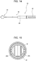
- FIG. 14 is a side view of a distal end portion of a snare member according to an embodiment.
- a snare member 82 illustrated in Fig. 14 includes a loop portion 84, an insertion portion 86, and an operation portion (not shown).
- the loop portion 84 is attached to a distal end part of an operation wire 90 inserted through the inside of the insertion portion 86 described below, and the operation portion is attached to a proximal end part of the insertion portion 86.
- the loop portion 84 is formed by bending a wire.
- the bent portion of the wire is oriented toward the distal end side.
- the loop diameter of the loop portion 84 decreases.
- the insertion portion 86 includes a sheath 88 and the operation wire 90.
- the operation wire 90 is inserted through the inside of the sheath so as to be movable back and forth.
- the loop portion 84 is attached to a distal end part of the sheath 88, and both end parts of the wire of the loop portion 84 are fixed to the distal end part of the operation wire 90.
- the loop portion 84 When the operator operates the operation portion and the operation wire 90 moves from the distal end side toward the proximal end side, the loop portion 84 is inserted into the sheath 88 and the loop diameter of the loop portion 84 decreases. On the other hand, when the operation wire 90 moves from the proximal end side toward the distal end side, the loop portion 84 is extruded from the distal end part of the sheath 88, and the diameter of the loop portion 84 increases.
- the insertion portion 86 of the snare member 82 is inserted from a treatment tool inlet of an endoscope (not shown), and the distal end part of the insertion portion 86 of the snare member 82, to be more specific, the loop portion 84 at the distal end part of the snare member 82 is extruded from a treatment tool outlet of the endoscope.
- the loop diameter of the loop portion 84 of the snare member 82 is increased.
- the loop diameter of the loop portion 84 which has been increased, is gradually reduced, the two arm portions 20A and 20B are fastened by the loop portion 84, and the two arm portions 20A and 20B are pressed from both sides of the outer surface in the direction (the first direction) in which the two arm portions 20A and 20B face each other and are moved in directions toward to each other.
- the two arm portions 20A and 20B are fastened and pressed from both sides of the outer surface in the first direction, and the two arm portions 20A and 20B move closer to each other; and as illustrated in the sectional view of the clip unit 12 in Fig. 15 , the end parts of the recessed portions of the two arm portions 20A and 20B, that is, the first recessed portion 26A and the second recessed portion 26B on the proximal end side move to positions where the end parts contact the inner peripheral surface of the tightening ring 18, and the clip body 16 and the tightening ring 18 are unlocked.
- the clip body 16 is moved from the proximal end side toward the distal end side relative to the tightening ring 18.
- the clip body 16 is moved from the proximal end side toward the distal end side relative to the tightening ring 18.
- the two arm portions 20A and 20B gradually open from the closed state due to an elastic force and finally enter the open state.
- the clip unit 12 is removed from the treatment part.
- the insertion portion of the endoscope is pulled out from the inside of the body of the patient.
- the insertion portion of the endoscope is pulled out from the inside of the body of the patient, and the clip unit 12, which has been removed from the treatment part, is also taken to the outside of the body of the patient at the same time.
- the action described above is repeatedly performed.
- the shapes of the folded portion 22 of the clip body 16 and the latch portion 58 of the coupling member 44 as seen in the second direction are not limited to substantial C-shapes.
- the shapes are not limited, as long as it is possible to latch the folded portion 22 and the latch portion 58 to each other.
- Latching means for latching the clip body 16 and the tightening ring 18 to each other is not limited to fitting of the first recessed portion 26A and the second recessed portion 26B of the two arm portions 20A and 20B into the tightening ring 18.
- the latching means is not limited, as long as it is possible to latch the clip body 16 and the tightening ring 18 to each other.
- the shape and size of the opening 50 of the pressing tube 42 are not limited, as long as at least a part of the exposed portion 60 of the coupling member 44 is exposed from the opening 50 and the distal end side of the first clamping member 56A can move from the opening 50 toward the outside of the pressing tube 42.
- Latching means for latching the clip body 16 and the coupling member 44 to each other is not limited to the latch portion 58, as long as it is possible to latch the clip body 16 and the coupling member 44 to each other.
- a latch portion may be provided also on the distal end side of the second clamping member 56B.
- an opening which includes an opening region similar to the middle part of the opening 50, is formed also at a position in the outer surface of the pressing tube 42 facing the outer surface of the second clamping member 56B.
- the shape and size of the exposed portion 60 of the coupling member 44 are not limited, as long as at least a part of the exposed portion 60 is exposed from the opening 50 of the pressing tube 42.
Landscapes
- Health & Medical Sciences (AREA)
- Life Sciences & Earth Sciences (AREA)
- Surgery (AREA)
- Molecular Biology (AREA)
- General Health & Medical Sciences (AREA)
- Veterinary Medicine (AREA)
- Engineering & Computer Science (AREA)
- Biomedical Technology (AREA)
- Heart & Thoracic Surgery (AREA)
- Medical Informatics (AREA)
- Public Health (AREA)
- Animal Behavior & Ethology (AREA)
- Nuclear Medicine, Radiotherapy & Molecular Imaging (AREA)
- Reproductive Health (AREA)
- Vascular Medicine (AREA)
- Surgical Instruments (AREA)
- Physics & Mathematics (AREA)
- Biophysics (AREA)
- Optics & Photonics (AREA)
- Pathology (AREA)
- Radiology & Medical Imaging (AREA)
Abstract
Description
- The present invention relates to a clip treatment tool for an endoscope, which is used, for example, to close a wound and to stop bleeding in a living body.
- A clip treatment tool for an endoscope is used, for example, to close a wound and to stop bleeding by extruding arm portions of a clip from a distal end of the endoscope, which is inserted into a living body, and by ligating a treatment part, such as the wound and the bleeding part, with distal end parts of the arm portions of the clip.
- Examples of such a clip treatment tool known to date include clip treatment tools that can freely open and close arm portions of a clip (see
JP5750619B JP4921173B US9339270B US2016/0367258A , andJP2008-289524A - However, once the treatment part has been ligated by the clip, the clip is placed in the body of the patient. Therefore, when the clip is placed in the body at a position displaced from a target position to be ligated due to an erroneous operation or the like, and when, for example, the clip placed in the body becomes unnecessary after the objective of using the clip, such as stoppage of bleeding, has been sufficiently achieved, the clip remains placed in the living body, and it is necessary to wait until the clip is naturally removed due to a change in body tissue of the patient. That is, there is a problem in that it is not possible to remove the clip at a desirable timing.
- An object of the present invention is to provide a clip treatment tool with which, after the clip has been once applied, it is possible to reliably maintain the applied state, and it is possible to remove a clip placed in a living body at any desirable timing.
- In order to achieve the object, the present invention provides a clip treatment tool including: a clip body that has two arm portions that face each other and open and close and a folded portion that connects proximal end parts of the two arm portions; a tightening ring that is attached to the two arm portions of the clip body and that functions to close the two arm portions in accordance with movement of the clip body from a distal end side toward a proximal end side; a pressing tube that has at least one opening formed in an outer surface thereof and extending in an axial direction, that has a distal end part to which the tightening ring is removably attached, and that allows the clip body to be contained therein in accordance with movement of the clip body from the distal end side toward the proximal end side; and a coupling member that has a distal end part to which the folded portion is removably connected and a proximal end part to which a distal end part of an operation wire is fixed, the coupling member coupling the clip body and the operation wire to each other. The coupling member is contained in the pressing tube.
- Preferably, the coupling member has an exposed portion at least a part of which is exposed from the opening, the exposed portion moves in the opening in the axial direction from the proximal end side toward the distal end side in accordance with movement of the coupling member from the proximal end side toward the distal end side, and the exposed portion moves in the opening in the axial direction from the distal end side toward the proximal end side in accordance with movement of the coupling member from the distal end side toward the proximal end side.
- Preferably, the opening has a first opening region, a second opening region, and a third opening region in order from the distal end side; and the two arm portions open in accordance with movement of the exposed portion in the first opening region from the proximal end side toward the distal end side, and the two arm portions close in accordance with movement of the exposed portion in the first opening region from the distal end side toward the proximal end side.
- Preferably, in accordance with movement of the exposed portion in the first opening region from the distal end side toward the proximal end side, the two arm portions are pressed by an end part of the tightening ring on the distal end side in directions toward each other and elastically deform, and the two arm portions gradually close from an open state and enter a closed state; and, in accordance with movement of the exposed portion in the first opening region from the proximal end side toward the distal end side, the two arm portions gradually open from the closed state due to an elastic force and enter the open state.
- Preferably, when the exposed portion moves to a boundary between the first opening region and the second opening region, the tightening ring and the two arm portions are latched to each other and the two arm portions enter the closed state, and the clip body is locked to the tightening ring while the two arm portions are in the closed state.
- Preferably, the coupling member has a clamping portion, the clamping portion has a first clamping member and a second clamping member, and the first clamping member has a latch portion on an inner surface of the first claiming member on the distal end side, the inner surface facing the second clamping member; the folded portion is clamped by the first clamping member and the second clamping member, the folded portion and the latch portion are latched to each other, and the coupling member and the clip body are latched to each other; and in a state in which the clip body is locked to the tightening ring, in accordance with movement of the exposed portion in the second opening region from the distal end side toward the proximal end side, the latch portion moves onto an end part of the folded portion on the proximal end side and moves from the distal end side toward the proximal end side, a distal end part of the first clamping member moves from the opening toward an outside of the pressing tube, the exposed portion moves from the second opening region into the third opening region, the latch portion moves over the end part of the folded portion on the proximal end side, the folded portion and the latch portion are unlatched from each other, and the clip body and the coupling member are separated from each other.
- Preferably, in a state in which the clip body and the coupling member are separated from each other, in accordance with movement of the operation wire from the proximal end side toward the distal end side, the coupling member moves from the proximal end side toward the distal end side, a proximal end part of the clip body is pushed toward the distal end side by the coupling member, and the tightening ring to which the clip body is locked and the pressing tube are separated from each other.
- Preferably, each of the two arm portions has, at both end parts thereof in a width direction, a recessed portion having a length in an extension direction larger than a size of the tightening ring in the axial direction; when the clip body moves from the distal end side toward the proximal end side and end parts of the recessed portions on the proximal end side move to positions beyond an end part of the tightening ring on the proximal end side, the two arm portions move in directions away from each other due to an elastic force, the tightening ring is latched to the recessed portions, and the clip body is locked to the tightening ring; in a state in which the tightening ring and the pressing tube are separated from each other, the tightening ring is squeezed from both sides of an outer peripheral surface thereof in directions in which the two arm portions face each other, the end parts of the recessed portions on the proximal end side move to positions where the end parts contact an inner peripheral surface of the tightening ring, and the clip body and the tightening ring are unlocked; and, in a state in which the clip body and the tightening ring are unlocked, in accordance with movement of the tightening ring relative to the clip body from the distal end side toward the proximal end side, the two arm portions open from the closed state and enter the open state.
- Preferably, each of the two arm portions has, at both end parts thereof in a width direction, a recessed portion having a length in an extension direction larger than a size of the tightening ring in the axial direction; when the clip body moves from the distal end side toward the proximal end side and end parts of the recessed portions on the proximal end side move to positions beyond an end part of the tightening ring on the proximal end side, the two arm portions move in directions away from each other due to an elastic force, the tightening ring is latched to the recessed portions, and the clip body is locked to the tightening ring; in a state in which the tightening ring and the pressing tube are separated from each other, the two arm portions are pressed from both sides of outer surfaces thereof in directions in which the two arm portions face each other, the end parts of the recessed portions on the proximal end side move to positions where the end parts contact an inner peripheral surface of the tightening ring, and the clip body and the tightening ring are unlocked; and, in a state in which the clip body and the tightening ring are unlocked, in accordance with movement of the clip body relative to the tightening ring from the proximal end side toward the distal end side, the two arm portions open from the closed state and enter the open state.
- With the present invention, until a treatment part is ligated by a clip unit, which is composed of the clip body and the tightening ring, it is possible to hold the treatment part over again by using the two arm portions; and, after the treatment part has been ligated by the clip unit, because the clip body and the tightening ring are locked, it is possible to reliably maintain the state in which the treatment part is ligated by the clip unit. Moreover, after the clip unit is placed at the treatment part, it is possible to remove the clip unit from the treatment part by unlocking the clip body and the tightening ring at any desirable timing.
-
-
Fig. 1A is a partial external side view of a clip treatment tool according to an embodiment of the present invention, in a state in which two arm portions of a clip body are in an open state; -
Fig. 1B is a sectional view taken along a chain line A-A inFig. 1A ; -
Fig. 2A is a partial external side view of the clip treatment tool according to the embodiment illustrated inFig. 1A , as seen in a different direction; -
Fig. 2B is a sectional view taken along a chain line B-B inFig. 2A ; -
Fig. 3 is an external perspective view of the clip body according to the embodiment; -
Fig. 4 is an enlarged external view of an opening of a pressing tube illustrated inFig. 1A ; -
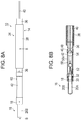
Fig. 5A is a partial external side view of the clip treatment tool according to the embodiment of the present invention, in a state in which the clip body is locked to a tightening ring; -
Fig. 5B is a sectional view taken along a chain line A-A inFig. 5A ; -
Fig. 6A is a partial external side view of the clip treatment tool according to the embodiment illustrated inFig. 5A , as seen in a different direction; -
Fig. 6B is a sectional view taken along a chain line B-B inFig. 6A ; -
Fig. 7A is a partial external side view of the clip treatment tool according to the embodiment of the present invention, in a state in which a coupling member is separated from the clip body; -
Fig. 7B is a sectional view taken along a chain line A-A inFig. 7A ; -
Fig. 8A is a partial external side view of the clip treatment tool according to the embodiment illustrated inFig. 7A , as seen in a different direction; -
Fig. 8B is a sectional view taken along a chain line B-B inFig. 8A ; -
Fig. 9A is a partial external side view of the clip treatment tool according to the embodiment of the present invention, in a state in which a clip unit and the pressing tube are separated from each other; -
Fig. 9B is a sectional view taken along a chain line A-A inFig. 9A ; -
Fig. 10A is a partial external side view of the clip treatment tool according to the embodiment illustrated inFig. 9A , as seen in a different direction; -
Fig. 10B is a sectional view taken along a chain line B-B inFig. 10A ; -
Fig. 11 is a sectional view taken along a chain line C-C inFig. 7B ; -
Fig. 12 is a side view illustrating a distal end portion of grasping forceps according to an embodiment; -
Fig. 13 is a sectional view of an embodiment in a state in which the clip body and the tightening ring are unlocked from a state in which the clip body is locked to the tightening ring as illustrated inFig. 11 ; -
Fig. 14 is a side view illustrating a distal end portion of a snare member according to an embodiment; and -
Fig. 15 is a sectional view of an embodiment in a state in which the clip body and the tightening ring are unlocked from a state in which the clip body is locked to the tightening ring as illustrated inFig. 11 . - Hereafter, a clip treatment tool according to the present invention will be described in detail based on preferred embodiments illustrated in the drawings.
-
Fig. 1A is a partial external side view of a clip treatment tool according to an embodiment of the present invention, in a state in which two arm portions of a clip body are in an open state.Fig. 1B is a sectional view taken along a chain line A-A inFig. 1A .Fig. 2A is a partial external side view of the clip treatment tool according to the embodiment illustrated inFig. 1A , as seen in a different direction.Fig. 2B is a sectional view taken along a chain line B-B inFig. 2A . - In the present embodiment, a first direction is defined as the direction in which the two arm portions of the clip body face each other (direction perpendicular to the plane of
Fig. 1B ), and a second direction is defined as the direction perpendicular to both of the first direction and the axial direction of a pressing tube (direction perpendicular to the plane ofFig. 1A ). In the clip treatment tool, a side on which a treatment part is located is defined as the distal end side, and a side on which an operator is located is defined as the proximal end side. - In all figures, in order to facilitate understanding, the dimensions, such as the thickness and the length, of each element of the present embodiment are appropriately changed from the actual dimensions, as necessary.
- A
clip treatment tool 10 illustrated inFigs. 1A, 1B ,2A, and 2B includes aclip unit 12 and atreatment tool body 14. When operated by an operator, for example, theclip treatment tool 10 is inserted from a treatment tool inlet of an operation portion of an endoscope, is extruded from a treatment tool outlet of a distal end surface of an insertion portion of the endoscope that has been inserted into the body of a patient, and ligates a treatment part by using theclip unit 12. - The
clip unit 12 includes aclip body 16 and a tighteningring 18. -
Fig. 3 is an external perspective view of the clip body according to the embodiment. - As illustrated in
Fig. 3 , theclip body 16 has two arm portions, which are afirst arm portion 20A and asecond arm portion 20B, that face each other and that open and close, and a foldedportion 22 that connects proximal end parts of the twoarm portions - The two
arm portions portion 22 are integrally formed by being bent respectively at a position between thefirst arm portion 20A and the foldedportion 22 and a position between thesecond arm portion 20B and the foldedportion 22. The foldedportion 22 has a substantial C-shape, as seen in the second direction. The twoarm portions - The
first arm portion 20A has a first protrudingportion 24A, a first recessedportion 26A, and afirst claw portion 28A, in order from the proximal end side. - The first protruding
portion 24A is formed between a proximal end part of thefirst arm portion 20A and the first recessedportion 26A. The first protrudingportion 24A has, at both end parts of thefirst arm portion 20A in the width direction (the second direction), an inclined part whose size in the width direction increases from the proximal end side toward the distal end side, and a flat part that is disposed on the distal end side of the inclined part and whose size in the width direction is constant. - The first recessed
portion 26A is formed between the first protrudingportion 24A and thefirst claw portion 28A. The first recessedportion 26A is formed, at both end parts of thefirst arm portion 20A in the width direction, so that the size thereof in the width direction is smaller than the size of each of the flat part of the first protrudingportion 24A and thefirst claw portion 28A in the width direction. The first recessedportion 26A is formed so that the length thereof in the extension direction is slightly larger than the size of the tighteningring 18 in the axial direction. - The
first claw portion 28A is formed at a distal end part of thefirst arm portion 20A. Thefirst claw portion 28A is formed by bending the distal end part of thefirst arm portion 20A by a constant angle in a direction toward thesecond arm portion 20B. - The
second arm portion 20B is configured similarly to thefirst arm portion 20A. Thesecond arm portion 20B has a second protrudingportion 24B, a second recessedportion 26B, and asecond claw portion 28B, which are respectively formed at positons corresponding to the first protrudingportion 24A, the first recessedportion 26A, and thefirst claw portion 28A of thefirst arm portion 20A. - The first protruding
portion 24A and the second protrudingportion 24B are portions that guide the tighteningring 18 to the first recessedportion 26A and the second recessedportion 26B. The first recessedportion 26A and the second recessedportion 26B are portions to which the tighteningring 18 is fitted. Thefirst claw portion 28A and thesecond claw portion 28B are portions for holding a treatment part therebetween and ligating the treatment part. - As illustrated in
Figs. 1B and2B , the tighteningring 18 has atightening ring body 30 and anattachment portion 32 for attaching the tighteningring 18 to apressing tube 42. The tighteningring body 30 and theattachment portion 32 are integrally formed. - The tightening
ring body 30 is a portion that protrudes from a distal end part of thepressing tube 42 toward the distal end side when the tighteningring 18 is attached to thepressing tube 42. The outside diameter of the tighteningring body 30 is substantially the same as the outside diameter of the distal end part of thepressing tube 42. An inclined part, whose inside diameter gradually decreases from the distal end side toward the proximal end side, is formed along the entire periphery of the inner peripheral surface of a distal end part of the tighteningring body 30. - The
attachment portion 32 is a portion that extends from a proximal end part of the tighteningring body 30 toward the proximal end side and that is inserted into thepressing tube 42 from the distal end part of thepressing tube 42. The outside diameter of theattachment portion 32 is slightly smaller than the inside diameter of the distal end part of thepressing tube 42. - As illustrated in
Figs. 1B and2B , the tighteningring 18 is attached to the twoarm portions clip body 16 in a state before theclip body 16 is locked to the tighteningring 18, that is, in a state in which the twoarm portions ring 18 is attached to parts of thefirst arm portion 20A and thesecond arm portion 20B on the proximal end side relative to the first protrudingportion 24A and the second protrudingportion 24B. - The tightening
ring 18 functions to open the twoarm portions clip body 16 relative to the tighteningring 18 from the proximal end side toward the distal end side, and to close the twoarm portions clip body 16 relative to the tighteningring 18 from the distal end side toward the proximal end side. - The
clip body 16 and the tighteningring 18 of theclip unit 12 are made of a material such as a stainless steel, titanium, or a cobalt-chrome alloy. Accordingly, even after theclip unit 12 is placed in the body of a patient, the patient can have a magnetic resonance imaging (MRI) scan. - The
treatment tool body 14 includes aninsertion portion 34 and an operation portion (not shown). - The
insertion portion 34 includes acoil sheath 36, atube sheath 38, anoperation wire 40, thepressing tube 42, and acoupling member 44. - The
coil sheath 36 and thetube sheath 38 are flexible tubes that are made of, for example, a fluorocarbon resin such as polytetrafluoroethylene (PTFE) or a resin material such as high-density polyethylene (HDPE). Thecoil sheath 36 is inserted through the inside of thetube sheath 38. As illustrated inFigs. 1B and2B , a recessed portion 46 is formed along the entire periphery of an outer peripheral surface of a distal end part of thecoil sheath 36. - The
operation wire 40 is made from, for example, a single wire or a stranded wire made of a metal. Theoperation wire 40 is inserted through the inside of thecoil sheath 36 so as to be movable in the axial direction of thecoil sheath 36. - When an operator operates an operation portion of the
clip treatment tool 10, theoperation wire 40 moves in thecoil sheath 36 toward the distal end side or the proximal end side. That is, the operator can push theoperation wire 40 from the proximal end side toward the distal end side or pull theoperation wire 40 from the distal end side toward the proximal end side. - The
pressing tube 42 is made of, for example, a material such as a stainless steel, titanium, or a cobalt-chrome alloy. - The inside diameter and the outside diameter of a proximal end part and a distal end part of the
pressing tube 42 are larger than the inside diameter of and the outside diameter of a middle part of thepressing tube 42 in the axial direction. As illustrated inFigs. 1B and2B , a protruding portion 48, which corresponds to the recessed portion 46 of thecoil sheath 36, is formed along the entire periphery of an inner peripheral surface of thepressing tube 42 on the proximal end side. The inside diameter of the proximal end part of thepressing tube 42 is slightly larger than the outside diameter of the distal end part of thecoil sheath 36. The proximal end part of thepressing tube 42 is attached to the distal end part of thecoil sheath 36 by pressing the distal end part of thecoil sheath 36 into the proximal end part of thepressing tube 42 and by fitting the protruding portion 48 of thepressing tube 42 and the recessed portion 46 of thecoil sheath 36 to each other. The tighteningring 18 is removably attached to the distal end part of thepressing tube 42 by inserting theattachment portion 32 of the tighteningring 18 into thepressing tube 42 from the distal end part. - The
pressing tube 42 allows theclip body 16 to be contained therein in accordance with movement of theclip body 16 relative to thepressing tube 42 from the distal end side toward the proximal end side. -
Fig. 4 is an enlarged external view of an opening of a pressing tube illustrated inFig. 1A . - As illustrated in
Fig. 4 , in the outer surface of thepressing tube 42, at least oneopening 50 extending in the axial direction of thepressing tube 42 is formed. Theopening 50 extends, in a middle part of thepressing tube 42 in the axial direction, linearly from the proximal end side toward the distal end side. Theopening 50 has afirst opening region 50A, asecond opening region 50B, and athird opening region 50C, in order from the distal end side. - The
first opening region 50A includes a middle part in the extension direction of theopening 50 and an opening region on the distal end side relative to the middle part. The size of the middle part of thefirst opening region 50A in the width direction is larger than the size of a part of thefirst opening region 50A on the distal end side relative to the middle part. - The
second opening region 50B is an opening region formed on the proximal end side of thefirst opening region 50A, that is, between thefirst opening region 50A and the third opening region. Thethird opening region 50C is an opening region formed on the proximal end side relative to thesecond opening region 50B. The size of each of thesecond opening region 50B and thethird opening region 50C in the width direction is substantially the same as the size of the part of thefirst opening region 50A on the distal end side relative to the middle part. - As illustrated in
Fig. 4 , in a middle part of the outer surface of thepressing tube 42 in the axial direction, anopening 52, which extends further from a distal end part of the first opening region toward the distal end side so as to be inclined at a constant angle with respect to the axial direction, is formed. - The
coupling member 44 has acoupling member body 54 and a clampingportion 56 as illustrated inFig. 1B , and is made of, for example, a biocompatible resin. Thecoupling member 44 is contained in thepressing tube 42. A distal end part of theoperation wire 40 is fixed to a proximal end part of thecoupling member body 54, that is, a proximal end part of thecoupling member 44. - The clamping
portion 56 is a portion that serves as a distal end part to which the foldedportion 22 of theclip body 16 is removably connected. The clampingportion 56 is disposed on the distal end side of thecoupling member body 54, and the clampingportion 56 and thecoupling member body 54 are integrally formed. The clampingportion 56 has afirst clamping member 56A and asecond clamping member 56B. Thefirst clamping member 56A and thesecond clamping member 56B extend parallelly from a distal end part of thecoupling member body 54 toward the distal end side so as to face each other. Thefirst clamping member 56A and thesecond clamping member 56B are disposed with a constant distance therebetween in the second direction. The distance between thefirst clamping member 56A and thesecond clamping member 56B is slightly larger than the size of the foldedportion 22 of theclip body 16 in the width direction. - The length of the
first clamping member 56A in the extension direction is slightly smaller than the length of the middle part of theopening 50 of thepressing tube 42 in the axial direction. The size of thefirst clamping member 56A in the width direction (the first direction) is slightly smaller than the size of the middle part (thefirst opening region 50A) of theopening 50 of thepressing tube 42 in the width direction (the first direction). The outer surface of thefirst clamping member 56A faces in the direction toward theopening 50 of thepressing tube 42. - As illustrated in
Figs. 1B and2B , thefirst clamping member 56A has alatch portion 58, which is latched to the foldedportion 22 of theclip body 16, on an inner surface of a distal end portion thereof facing thesecond clamping member 56B. Thelatch portion 58 protrudes from thefirst clamping member 56A toward thesecond clamping member 56B. Thelatch portion 58 has an inclined part that is formed so that the height thereof in the second direction increases from the proximal end side toward the distal end side, and a flat part that is disposed on the distal end side of the inclined part and that has a constant height. The shape of thelatch portion 58 as seen in the second direction is a substantial C-shape, which is the same as the shape of the foldedportion 22 of theclip body 16 as seen in the second direction. The outside diameter of the shape of thelatch portion 58 is slightly larger than the inside diameter of the shape of a space that is formed by the foldedportion 22 when the foldedportion 22 is seen in the second direction. - The folded
portion 22 of theclip body 16 is clamped by thefirst clamping member 56A and thesecond clamping member 56B from both sides in the second direction; thelatch portion 58, which protrudes from thefirst clamping member 56A toward thesecond clamping member 56B, is inserted into the space formed by the foldedportion 22 when the foldedportion 22 is seen in the second direction; the foldedportion 22 and thelatch portion 58 are latched to each other; and thecoupling member 44 are theclip body 16 are removably latched to each other. - Because the distal end part of the
coupling member 44 is removably latched to the foldedportion 22 in this way and the distal end part of theoperation wire 40 is fixed to the proximal end part of thecoupling member 44, theclip body 16 and theoperation wire 40 are coupled to each other by thecoupling member 44. - In accordance with movement of the
operation wire 40 from the proximal end side toward the distal end side, thecoupling member 44 is moved in thepressing tube 42 from the proximal end side toward the distal end side. In accordance with movement of theoperation wire 40 from the distal end side toward the proximal end side, thecoupling member 44 is moved in thepressing tube 42 from the distal end side toward the proximal end side. - The
coupling member 44 has an exposedportion 60, at least a part of which is exposed from theopening 50 of thepressing tube 42, on an outer surface thereof between thefirst clamping member 56A and thecoupling member body 54. The size of the exposedportion 60 of thecoupling member 44 in the width direction (the first direction) is slightly smaller than the size, in the width direction, of each of a part of theopening 50 of thepressing tube 42 on the distal end side relative to the middle part of the opening 50 (the first opening region), thesecond opening region 50B, thethird opening region 50C, and theopening 52. - When inserting the
coupling member 44 into thepressing tube 42 from the distal end part of thepressing tube 42, theopening 52 in the outer surface of thepressing tube 42 serves as a guide groove that guides thecoupling member 44 into thepressing tube 42. The exposedportion 60 is moved from the distal end side toward the proximal end side in the extension direction of theopening 52, and is guided to the distal end part of thefirst opening region 50A. - The exposed
portion 60 according to the present embodiment is a pin-shaped projection. When thecoupling member 44 reciprocates in thepressing tube 42 in the axial direction, the exposedportion 60 reciprocates in the same way in theopening 50 of the pressing tube 42 (thefirst opening region 50A, thesecond opening region 50B, and thethird opening region 50C). That is, the exposedportion 60 moves in theopening 50 of thepressing tube 42 in the axial direction of thepressing tube 42 from the proximal end side toward the distal end side in accordance with movement of thecoupling member 44 from the proximal end side toward the distal end side, and the exposedportion 60 moves in theopening 50 of thepressing tube 42 in the axial direction of thepressing tube 42 from the distal end side toward the proximal end side in accordance with movement of thecoupling member 44 from the distal end side toward the proximal end side. The exposedportion 60 may be called a guide member that prevents rotation and the like of thecoupling member 44 when thecoupling member 44 reciprocates. The opening region of thefirst opening region 50A of theopening 50 on the distal end side relative to the middle part, thesecond opening region 50B, and thethird opening region 50C serve as a guide groove for the guide member. - The operation portion of the
treatment tool body 14 has an operation portion body, a slider, and the like (not shown). - A distal end part of the operation portion body is attached to a proximal end part of the
coil sheath 36. - The slider is a portion that moves the
operation wire 40 relative to thecoil sheath 36 toward the distal end side or the proximal end side. The slider is slidable relative to the operation portion body toward the distal end side or the proximal end side. A proximal end part of theoperation wire 40 is fixed to a distal end part of the slider. - When an operator operates the operation portion of the
clip treatment tool 10 and the slider is moved from the distal end side toward the proximal end side relative to the operation portion body, theoperation wire 40 is moved from the distal end side toward the proximal end side. When the slider is moved from the proximal end side toward the distal end side relative to the operation portion body, theoperation wire 40 is moved from the proximal end side toward the distal end side. - Next, actions of the
clip treatment tool 10 will be described. - First, an action that is performed when ligating a treatment part by using the
clip unit 12 will be described. In the following description, it is assumed that an insertion portion of an endoscope (not shown) has already been inserted into the body of a patient. - First, when operated by an operator, the
insertion portion 34 of theclip treatment tool 10 is inserted from a treatment tool inlet of the endoscope (not shown), and a distal end part of theinsertion portion 34 of theclip treatment tool 10, to be more specific, a distal end part of theclip unit 12 is extruded from a treatment tool outlet of the endoscope. - Next, when the operator operates the operation portion of the
clip treatment tool 10, theoperation wire 40 is moved from the proximal end side toward the distal end side. - In accordance with movement of the
operation wire 40 from the proximal end side toward the distal end side, thecoupling member 44 and theclip body 16 move from the proximal end side toward the distal end side, and the twoarm portions clip body 16 enter an open state as illustrated inFigs. 1A, 1B ,2A, and 2B . - Next, when operated by the operator, the
insertion portion 34 of theclip treatment tool 10 is moved from the proximal end side toward the distal end side, and the distal end parts of the twoarm portions - Next, in the state in which the distal end parts of the two
arm portions clip treatment tool 10, theoperation wire 40 is moved from the distal end side toward the proximal end side. - In accordance with movement of the
operation wire 40 from the distal end side toward the proximal end side, thecoupling member 44 moves from the distal end side toward the proximal end side, and the exposedportion 60 of thecoupling member 44 moves from the distal end side toward the proximal end side along theopening 50 of thepressing tube 42. Moreover, in accordance with movement of thecoupling member 44 from the distal end side toward the proximal end side, theclip body 16 moves from the distal end side toward the proximal end side, the twoarm portions ring 18 on the distal end side in directions toward each other and elastically deform, and the twoarm portions - In a state before the
clip body 16 is locked to the tighteningring 18, the twoarm portions coupling member 44 from the proximal end side toward the distal end side, that is, in accordance with movement of the exposedportion 60 in thefirst opening region 50A of thepressing tube 42 from the proximal end side toward the distal end side; and the twoarm portions coupling member 44 from the distal end side toward the proximal end side, that is, in accordance with movement of the exposedportion 60 in thefirst opening region 50A of thepressing tube 42 from the distal end side toward the proximal end side. - In accordance with movement of the
coupling member 44 from the distal end side toward the proximal end side, that is, in accordance with movement of the exposedportion 60 in thefirst opening region 50A of thepressing tube 42 from the distal end side toward the proximal end side, theclip body 16 moves from the distal end side toward the proximal end side, the twoarm portions ring 18 on the distal end side in directions toward each other and elastically deform, and the twoarm portions - On the other hand, in accordance with movement of the
coupling member 44 from the proximal end side toward the distal end side, that is, in accordance with movement of the exposedportion 60 in thefirst opening region 50A from the proximal end side toward the distal end side, theclip body 16 moves from the proximal end side toward the distal end side, and the twoarm portions - When the
clip body 16 moves toward the distal end side or the proximal end side, both end parts of the twoarm portions ring body 30 make point contact, and the twoarm portions ring body 30. - When the two
arm portions ring body 30, the inclined parts of the first protrudingportion 24A and the second protrudingportion 24B of the twoarm portions ring body 30 function to reduce friction between the twoarm portions ring body 30 and to facilitate movement of theclip body 16 relative to the tighteningring 18 toward the distal end side or the proximal end side. - Thus, in the state before the
clip body 16 is locked to the tighteningring 18, it is possible to hold a treatment part over again by using thefirst claw portion 28A and thesecond claw portion 28B of the twoarm portions arm portions - Next, in the state in which the treatment part is held by the
first claw portion 28A and thesecond claw portion 28B of the twoarm portions operation wire 40 is moved further from the distal end side toward the proximal end side. - Accordingly, the
coupling member 44 and theclip body 16 move further from the distal end side toward the proximal end side. As illustrated inFigs. 5A, 5B ,6A, and 6B , when the exposedportion 60 moves to a boundary between thefirst opening region 50A and thesecond opening region 50B, the tighteningring 18 and the twoarm portions arm portions - To be more specific, when the
coupling member 44 and theclip body 16 move further from the distal end side toward the proximal end side and end parts of the recessed portions of the twoarm portions portion 26A and the second recessedportion 26B on the proximal end side move to positions beyond an end part of the tighteningring 18 on the proximal end side, as illustrated inFig. 11 , the twoarm portions Fig. 5B , the tighteningring 18 is fitted into and latched to the recessedportions arm portions arm portions - Thus, as illustrated in
Figs. 5A, 5B ,6A, and 6B , theclip body 16 is locked to the tighteningring 18 while the twoarm portions first claw portion 28A and thesecond claw portion 28B of the twoarm portions - Next, in the state in which the
clip body 16 is locked to the tighteningring 18, that is, in the state in which the treatment part is ligated by thefirst claw portion 28A and thesecond claw portion 28B of the twoarm portions operation wire 40 is moved further from the distal end side toward the proximal end side. - Accordingly, the
coupling member 44 and theclip body 16 move further from the distal end side toward the proximal end side, and the exposedportion 60 of thecoupling member 44 moves in thesecond opening region 50B from the distal end side toward the proximal end side. - In accordance with movement of the exposed
portion 60 in thesecond opening region 50B from the distal end side toward the proximal end side, the inclined part of thelatch portion 58 of thecoupling member 44 moves onto an end part of the foldedportion 22 of theclip body 16 on the proximal end side and moves from the distal end side toward the proximal end side, and the distal end part of thefirst clamping member 56A moves from the middle part of theopening 50 of the pressing tube 42 (the first opening region) toward the outside of thepressing tube 42. That is, the distal end part of thefirst clamping member 56A is pushed from the middle part of theopening 50 toward the outside of thepressing tube 42. - When the exposed
portion 60 moves in thesecond opening region 50B, because rotation of the exposedportion 60 is restricted by thesecond opening region 50B that serves as a guide groove, rotation of thecoupling member 44 is restricted. Thus, the position of thefirst clamping member 56A and the position of theopening 50 of thepressing tube 42 are adjusted so as to coincide with each other, and the distal end part of thefirst clamping member 56A can move from the middle part of theopening 50 of the pressing tube 42 (the first opening region) toward the outside of thepressing tube 42. - The
coupling member 44 and theclip body 16 move further from the distal end side toward the proximal end side; and, as illustrated inFigs. 7A, 7B ,8A, and 8B , the exposedportion 60 moves from thesecond opening region 50B into thethird opening region 50C, thelatch portion 58 moves over the end part of the foldedportion 22 on the proximal end side, the foldedportion 22 and thelatch portion 58 are unlatched from each other, and theclip body 16 and thecoupling member 44 are separated from each other. - When the
coupling member 44 is moved from the distal end side toward the proximal end side in the state in which the foldedportion 22 and thelatch portion 58 are latched to each other, the inclined surface of the inclined part of thelatch portion 58 and an end part of a proximal end part of the foldedportion 22 on thefirst clamping member 56A side make line contact, and the inclined part of thelatch portion 58 slides along the end part on thefirst clamping member 56A side of the proximal end side of the foldedportion 22. - When the
latch portion 58 slides along the end part of the proximal end part of the foldedportion 22 on thefirst clamping member 56A side, the inclined part of thelatch portion 58 functions to reduce friction between thelatch portion 58 and the foldedportion 22 and to facilitate movement of thelatch portion 58 from the distal end side toward the proximal end side relative the foldedportion 22. - Next, in the state in which the
clip body 16 and thecoupling member 44 are separated from each other, theoperation wire 40 is moved from the proximal end side toward the distal end side. - In accordance with movement of the
operation wire 40 from the proximal end side toward the distal end side, thecoupling member 44 moves from the proximal end side toward the distal end side, and the distal end part of thecoupling member 44 contacts the proximal end part of the foldedportion 22 of theclip body 16. In accordance with further movement of thecoupling member 44 from the proximal end side toward the distal end side, the proximal end part of theclip body 16 is pushed by thecoupling member 44 toward the distal end side; and, as illustrated inFigs. 9A, 9B ,10A, and 10B , the tighteningring 18, to which theclip body 16 is locked, and thepressing tube 42 are separated from each other. Thus, in the state in which a treatment part is ligated by theclip unit 12, theclip unit 12 is placed at the treatment part. - Subsequently, when operated by the operator, in the state in which the
insertion portion 34 of theclip treatment tool 10 is still inserted into the endoscope, the insertion portion of the endoscope is pulled out from the inside of the body of the patient. To ligate a plurality of treatment parts, the action described above is repeatedly performed. - Next, actions that are performed to remove the
clip unit 12 from a treatment part will be described. - First, an action that is performed to remove the
clip unit 12 by using a grasping member, such as grasping forceps, will be described. -
Fig. 12 is a side view of a distal end portion of grasping forceps according to an embodiment. Graspingforceps 70 illustrated inFig. 12 include a graspingportion 72, aninsertion portion 74, and an operation portion (not shown). The graspingportion 72 is attached to a distal end part of theinsertion portion 74, and the operation portion is attached to a proximal end part of theinsertion portion 74. - The grasping
portion 72 has a pair ofclaw members claw members claw members - The
insertion portion 74 includes asheath 78 and anoperation wire 80. - The
operation wire 80 is inserted through the inside of thesheath 78 so as to be movable back and forth. The graspingportion 72 is attached to a distal end part of thesheath 78, and a distal end part of theoperation wire 80 is fixed to proximal end parts of theclaw members portion 72. - When the operator operates the operation portion and the
operation wire 80 moves from the distal end side toward the proximal end side, the pair ofclaw members operation wire 80 moves from the proximal end side toward the distal end side, the pair ofclaw members - To remove the
clip unit 12, first, when operated by the operator, theinsertion portion 74 of the graspingforceps 70 is inserted from a treatment tool inlet of an endoscope (not shown), and the distal end part of theinsertion portion 74 of the graspingforceps 70, to be more specific, the graspingportion 72 at the distal end part of the graspingforceps 70 is extruded from a treatment tool outlet of the endoscope. - Next, in the state in which the tightening
ring 18 and thepressing tube 42 are separated from each other, that is, in the state in which theclip unit 12 ligates a treatment part and is placed at the treatment part, when the operator operates the operation portion of the graspingforceps 70, theclaw members portion 72 of the graspingforceps 70 are caused to enter the open state. Next, theclaw members portion 72 in the open state are gradually closed, the tighteningring 18 is pressed by theclaw members arm portions ring 18 is squeezed from the both sides of the outer peripheral surface in the first direction. - The tightening
ring 18 is squeezed from both sides of the outer peripheral surface in the first direction, and the twoarm portions ring 18; and as illustrated in the sectional view of theclip unit 12 inFig. 13 , the ends parts of the recessed portions of the twoarm portions portion 26A and the second recessedportion 26B on the proximal end side move to positions where the end parts contact the inner peripheral surface of the tighteningring 18, and theclip body 16 and the tighteningring 18 are unlocked. - Next, in the state in which the
clip body 16 and the tighteningring 18 are unlocked, the tighteningring 18 is moved from the distal end side toward the proximal end side relative to theclip body 16. For example, in the state in which the tighteningring 18 is clamped by theclaw members portion 72 of the graspingforceps 70, when operated by the operator and in accordance with movement of the graspingforceps 70 move from the distal end side toward the proximal end side, the tighteningring 18 is moved relative to theclip body 16 from the distal end side toward the proximal end side. - In accordance with movement of the tightening
ring 18 relative to theclip body 16 from the distal end side toward the proximal end side, the twoarm portions clip unit 12 is removed from the treatment part. - Subsequently, when operated by the operator, in the state in which the
insertion portion 74 of the graspingforceps 70 is still inserted into the endoscope, the insertion portion of the endoscope is pulled out from the inside of the body of the patient. For example, in the state in which the tighteningring 18 is clamped by theclaw members portion 72 of the graspingforceps 70, the insertion portion of the endoscope is pulled out from the inside of the body of the patient, and theclip unit 12, which has been removed from the treatment part, is also taken to the outside of the body of the patient at the same time. To remove a plurality ofclip units 12 from treatment parts, the action described above is repeatedly performed. - Next, an action that is performed to remove the
clip unit 12 by using a snare member will be described. -
Fig. 14 is a side view of a distal end portion of a snare member according to an embodiment. Asnare member 82 illustrated inFig. 14 includes aloop portion 84, aninsertion portion 86, and an operation portion (not shown). Theloop portion 84 is attached to a distal end part of anoperation wire 90 inserted through the inside of theinsertion portion 86 described below, and the operation portion is attached to a proximal end part of theinsertion portion 86. - The
loop portion 84 is formed by bending a wire. The bent portion of the wire is oriented toward the distal end side. When an operator operates the operation portion, the loop diameter of theloop portion 84 decreases. - The
insertion portion 86 includes asheath 88 and theoperation wire 90. - The
operation wire 90 is inserted through the inside of the sheath so as to be movable back and forth. Theloop portion 84 is attached to a distal end part of thesheath 88, and both end parts of the wire of theloop portion 84 are fixed to the distal end part of theoperation wire 90. - When the operator operates the operation portion and the
operation wire 90 moves from the distal end side toward the proximal end side, theloop portion 84 is inserted into thesheath 88 and the loop diameter of theloop portion 84 decreases. On the other hand, when theoperation wire 90 moves from the proximal end side toward the distal end side, theloop portion 84 is extruded from the distal end part of thesheath 88, and the diameter of theloop portion 84 increases. - To remove the
clip unit 12, first, when operated by the operator, theinsertion portion 86 of thesnare member 82 is inserted from a treatment tool inlet of an endoscope (not shown), and the distal end part of theinsertion portion 86 of thesnare member 82, to be more specific, theloop portion 84 at the distal end part of thesnare member 82 is extruded from a treatment tool outlet of the endoscope. - Next, in the state in which the tightening
ring 18 and thepressing tube 42 are separated from each other, that is, in the state in which theclip unit 12 ligates a treatment part and is placed at the treatment part, when the operator operates the operation portion of thesnare member 82, the loop diameter of theloop portion 84 of thesnare member 82 is increased. Next, the loop diameter of theloop portion 84, which has been increased, is gradually reduced, the twoarm portions loop portion 84, and the twoarm portions arm portions - The two
arm portions arm portions clip unit 12 inFig. 15 , the end parts of the recessed portions of the twoarm portions portion 26A and the second recessedportion 26B on the proximal end side move to positions where the end parts contact the inner peripheral surface of the tighteningring 18, and theclip body 16 and the tighteningring 18 are unlocked. - Next, in the state in which the
clip body 16 and the tighteningring 18 are unlocked, theclip body 16 is moved from the proximal end side toward the distal end side relative to the tighteningring 18. For example, in the state in which the twoarm portions loop portion 84 of thesnare member 82, when operated by the operator and in accordance with movement thesnare member 82 from the proximal end side toward the distal end side, theclip body 16 is moved from the proximal end side toward the distal end side relative to the tighteningring 18. - In accordance with movement of the
clip body 16 relative to the tighteningring 18 from the proximal end side toward the distal end side, the twoarm portions clip unit 12 is removed from the treatment part. - Subsequently, when operated by the operator, in the state in which the
insertion portion 86 of thesnare member 82 is still inserted into the endoscope, the insertion portion of the endoscope is pulled out from the inside of the body of the patient. For example, in the state in which the twoarm portions loop portion 84 of thesnare member 82, the insertion portion of the endoscope is pulled out from the inside of the body of the patient, and theclip unit 12, which has been removed from the treatment part, is also taken to the outside of the body of the patient at the same time. To remove a plurality ofclip units 12 from treatment parts, the action described above is repeatedly performed. - With the
clip treatment tool 10, until a treatment part is ligated by theclip unit 12, it is possible to hold the treatment part over again by using the twoarm portions clip unit 12, because theclip body 16 and the tighteningring 18 are locked, it is possible to reliably maintain the state in which the treatment part is ligated by theclip unit 12. Moreover, after theclip unit 12 is placed at the treatment part, it is possible to remove theclip unit 12 from the treatment part by unlocking theclip body 16 and the tighteningring 18 at any desirable timing. - The shapes of the folded
portion 22 of theclip body 16 and thelatch portion 58 of thecoupling member 44 as seen in the second direction are not limited to substantial C-shapes. The shapes are not limited, as long as it is possible to latch the foldedportion 22 and thelatch portion 58 to each other. - Latching means for latching the
clip body 16 and the tighteningring 18 to each other is not limited to fitting of the first recessedportion 26A and the second recessedportion 26B of the twoarm portions ring 18. The latching means is not limited, as long as it is possible to latch theclip body 16 and the tighteningring 18 to each other. - The shape and size of the
opening 50 of thepressing tube 42 are not limited, as long as at least a part of the exposedportion 60 of thecoupling member 44 is exposed from theopening 50 and the distal end side of thefirst clamping member 56A can move from theopening 50 toward the outside of thepressing tube 42. - Latching means for latching the
clip body 16 and thecoupling member 44 to each other is not limited to thelatch portion 58, as long as it is possible to latch theclip body 16 and thecoupling member 44 to each other. - Although the
latch portion 58 is provided only on the distal end side of thefirst clamping member 56A thecoupling member 44, a latch portion may be provided also on the distal end side of thesecond clamping member 56B. In this case, in order that the distal end part of thesecond clamping member 56B can be pushed toward the outside of thepressing tube 42, an opening, which includes an opening region similar to the middle part of theopening 50, is formed also at a position in the outer surface of thepressing tube 42 facing the outer surface of thesecond clamping member 56B. - The shape and size of the exposed
portion 60 of thecoupling member 44 are not limited, as long as at least a part of the exposedportion 60 is exposed from theopening 50 of thepressing tube 42. - Heretofore, the present invention has been described in detail. The present invention is not limited to the embodiment described above, and naturally, various improvements and modifications are possible within the spirit and scope of the present invention.
-
- 10
- clip treatment tool
- 12
- clip unit
- 14
- treatment tool body
- 16
- clip body
- 18
- tightening ring
- 20A
- first arm portion
- 20B
- second arm portion
- 22
- folded portion
- 24A
- first protruding portion
- 26A
- first recessed portion
- 28A
- first claw portion
- 24B
- second protruding portion
- 26B
- second recessed portion
- 28B
- second claw portion
- 30
- tightening ring body
- 32
- attachment portion
- 34, 74, 86
- insertion portion
- 36
- coil sheath
- 38
- tube sheath
- 40, 80, 90
- operation wire
- 42
- pressing tube
- 44
- coupling member
- 46
- recessed portion
- 48
- protruding portion
- 50, 52
- opening
- 50A
- first opening region
- 50B
- second opening region
- 50C
- third opening region
- 54
- coupling member body
- 56
- clamping portion
- 56A
- first clamping member
- 56B
- second clamping member
- 58
- latch portion
- 60
- exposed portion
- 70
- grasping forceps
- 72
- grasping portion
- 76A, 76B
- claw member
- 78, 88
- sheath
- 82
- snare member
- 84
- loop portion
Claims (9)
- A clip treatment tool comprising:a clip body that has two arm portions that face each other and open and close and a folded portion that connects proximal end parts of the two arm portions;a tightening ring that is attached to the two arm portions of the clip body and that functions to close the two arm portions in accordance with movement of the clip body from a distal end side toward a proximal end side;a pressing tube that has at least one opening formed in an outer surface thereof and extending in an axial direction, that has a distal end part to which the tightening ring is removably attached, and that allows the clip body to be contained therein in accordance with movement of the clip body from the distal end side toward the proximal end side; anda coupling member that has a distal end part to which the folded portion is removably connected and a proximal end part to which a distal end part of an operation wire is fixed, the coupling member coupling the clip body and the operation wire to each other,wherein the coupling member is contained in the pressing tube.
- The clip treatment tool according to claim 1,
wherein the coupling member has an exposed portion at least a part of which is exposed from the opening, the exposed portion moves in the opening in the axial direction from the proximal end side toward the distal end side in accordance with movement of the coupling member from the proximal end side toward the distal end side, and the exposed portion moves in the opening in the axial direction from the distal end side toward the proximal end side in accordance with movement of the coupling member from the distal end side toward the proximal end side. - The clip treatment tool according to claim 2,
wherein the opening has a first opening region, a second opening region, and a third opening region in order from the distal end side, and
wherein the two arm portions open in accordance with movement of the exposed portion in the first opening region from the proximal end side toward the distal end side, and the two arm portions close in accordance with movement of the exposed portion in the first opening region from the distal end side toward the proximal end side. - The clip treatment tool according to claim 3,
wherein, in accordance with movement of the exposed portion in the first opening region from the distal end side toward the proximal end side, the two arm portions are pressed by an end part of the tightening ring on the distal end side in directions toward each other and elastically deform, and the two arm portions gradually close from an open state and enter a closed state; and, in accordance with movement of the exposed portion in the first opening region from the proximal end side toward the distal end side, the two arm portions gradually open from the closed state due to an elastic force and enter the open state. - The clip treatment tool according to claim 4,
wherein, when the exposed portion moves to a boundary between the first opening region and the second opening region, the tightening ring and the two arm portions are latched to each other and the two arm portions enter the closed state, and the clip body is locked to the tightening ring while the two arm portions are in the closed state. - The clip treatment tool according to claim 5,
wherein the coupling member has a clamping portion, the clamping portion has a first clamping member and a second clamping member, and the first clamping member has a latch portion on an inner surface of the first claiming member on the distal end side, the inner surface facing the second clamping member,
wherein the folded portion is clamped by the first clamping member and the second clamping member, the folded portion and the latch portion are latched to each other, and the coupling member and the clip body are latched to each other, and
wherein, in a state in which the clip body is locked to the tightening ring, in accordance with movement of the exposed portion in the second opening region from the distal end side toward the proximal end side, the latch portion moves onto an end part of the folded portion on the proximal end side and moves from the distal end side toward the proximal end side, a distal end part of the first clamping member moves from the opening toward an outside of the pressing tube, the exposed portion moves from the second opening region into the third opening region, the latch portion moves over the end part of the folded portion on the proximal end side, the folded portion and the latch portion are unlatched from each other, and the clip body and the coupling member are separated from each other. - The clip treatment tool according to claim 6,
wherein, in a state in which the clip body and the coupling member are separated from each other, in accordance with movement of the operation wire from the proximal end side toward the distal end side, the coupling member moves from the proximal end side toward the distal end side, a proximal end part of the clip body is pushed toward the distal end side by the coupling member, and the tightening ring to which the clip body is locked and the pressing tube are separated from each other. - The clip treatment tool according to claim 7,
wherein each of the two arm portions has, at both end parts thereof in a width direction, a recessed portion having a length in an extension direction larger than a size of the tightening ring in the axial direction,
wherein, when the clip body moves from the distal end side toward the proximal end side and end parts of the recessed portions on the proximal end side move to positions beyond an end part of the tightening ring on the proximal end side, the two arm portions move in directions away from each other due to an elastic force, the tightening ring is latched to the recessed portions, and the clip body is locked to the tightening ring,
wherein, in a state in which the tightening ring and the pressing tube are separated from each other, the tightening ring is squeezed from both sides of an outer peripheral surface thereof in directions in which the two arm portions face each other, the end parts of the recessed portions on the proximal end side move to positions where the end parts contact an inner peripheral surface of the tightening ring, and the clip body and the tightening ring are unlocked, and
wherein, in a state in which the clip body and the tightening ring are unlocked, in accordance with movement of the tightening ring relative to the clip body from the distal end side toward the proximal end side, the two arm portions open from the closed state and enter the open state. - The clip treatment tool according to claim 7,
wherein each of the two arm portions has, at both end parts thereof in a width direction, a recessed portion having a length in an extension direction larger than a size of the tightening ring in the axial direction,
wherein, when the clip body moves from the distal end side toward the proximal end side and end parts of the recessed portions on the proximal end side move to positions beyond an end part of the tightening ring on the proximal end side, the two arm portions move in directions away from each other due to an elastic force, the tightening ring is latched to the recessed portions, and the clip body is locked to the tightening ring,
wherein, in a state in which the tightening ring and the pressing tube are separated from each other, the two arm portions are pressed from both sides of outer surfaces thereof in directions in which the two arm portions face each other, the end parts of the recessed portions on the proximal end side move to positions where the end parts contact an inner peripheral surface of the tightening ring, and the clip body and the tightening ring are unlocked, and
wherein, in a state in which the clip body and the tightening ring are unlocked, in accordance with movement of the clip body relative to the tightening ring from the proximal end side toward the distal end side, the two arm portions open from the closed state and enter the open state.
Applications Claiming Priority (2)
| Application Number | Priority Date | Filing Date | Title |
|---|---|---|---|
| JP2017121591 | 2017-06-21 | ||
| PCT/JP2018/015206 WO2018235404A1 (en) | 2017-06-21 | 2018-04-11 | Clip treatment tool |
Publications (3)
| Publication Number | Publication Date |
|---|---|
| EP3643253A1 true EP3643253A1 (en) | 2020-04-29 |
| EP3643253A4 EP3643253A4 (en) | 2020-05-27 |
| EP3643253B1 EP3643253B1 (en) | 2024-12-11 |
Family
ID=64735606
Family Applications (1)
| Application Number | Title | Priority Date | Filing Date |
|---|---|---|---|
| EP18820282.4A Active EP3643253B1 (en) | 2017-06-21 | 2018-04-11 | Clipping tool |
Country Status (5)
| Country | Link |
|---|---|
| US (1) | US11013517B2 (en) |
| EP (1) | EP3643253B1 (en) |
| JP (1) | JP6858258B2 (en) |
| CN (1) | CN110769765B (en) |
| WO (1) | WO2018235404A1 (en) |
Families Citing this family (5)
| Publication number | Priority date | Publication date | Assignee | Title |
|---|---|---|---|---|
| CN113316424B (en) * | 2019-01-03 | 2024-09-27 | 奥林巴斯株式会社 | Clamping device for large defects, perforations and fistulas |
| CN111481287B (en) * | 2020-04-03 | 2021-03-23 | 桐庐洲济医疗器械有限公司 | Adjustable electrocoagulator |
| JP7672158B2 (en) * | 2020-04-17 | 2025-05-07 | 国立大学法人愛媛大学 | Clip removal device |
| JP7625088B2 (en) * | 2021-01-13 | 2025-01-31 | 杭州安杰思医学科技股▲ふん▼有限公司 | Clip apparatus, clip device and method for unlocking clip |
| US11937828B2 (en) * | 2021-01-26 | 2024-03-26 | Olympus Medical Systems Corp. | Endoscope treatment device |
Family Cites Families (16)
| Publication number | Priority date | Publication date | Assignee | Title |
|---|---|---|---|---|
| JPS4921173B1 (en) | 1970-01-29 | 1974-05-30 | ||
| FR2381594A1 (en) | 1977-02-24 | 1978-09-22 | Centre Techn Ind Mecanique | ELECTROCHEMICAL MACHINING PROCESS OF POLYPHASIC ALLOYS |
| DE4319829C1 (en) * | 1993-06-16 | 1994-08-25 | Lerch Karl Dieter | Set for treating vascular deformities |
| JP3776529B2 (en) * | 1996-02-29 | 2006-05-17 | オリンパス株式会社 | Clip device |
| WO2004082488A1 (en) * | 2003-03-17 | 2004-09-30 | Sumitomo Bakelite Company Limited | Clip and clipping instrument for biological tissues |
| EP3878381A3 (en) | 2003-09-30 | 2021-11-10 | Boston Scientific Scimed, Inc. | Through the scope tension member release clip |
| JP4910879B2 (en) * | 2007-05-22 | 2012-04-04 | 住友ベークライト株式会社 | Medical clip device, its elastic clip unit and flexible tube unit |
| JP5045485B2 (en) * | 2008-02-18 | 2012-10-10 | 日本ゼオン株式会社 | Endoscope clip attachment |
| US20110054498A1 (en) * | 2008-05-05 | 2011-03-03 | Niti Surgical Solutions Ltd. | Endoscopic compression clip and system and method for use thereof |
| US8409223B2 (en) * | 2008-08-29 | 2013-04-02 | Covidien Lp | Endoscopic surgical clip applier with clip retention |
| SI2627268T1 (en) | 2010-10-11 | 2017-10-30 | Cook Medical Technologies Llc | Medical devices with detachable pivotable jaws |
| JP5427857B2 (en) * | 2011-09-15 | 2014-02-26 | 富士フイルム株式会社 | Clip unit, ligating apparatus using the same, and manufacturing method of clip unit |
| WO2013067662A1 (en) * | 2011-11-11 | 2013-05-16 | Zhu Jian | Clamping or ligating device |
| JP5750619B2 (en) | 2013-05-07 | 2015-07-22 | オリンパス株式会社 | Clip unit |
| CN103989500B (en) | 2014-05-23 | 2015-11-18 | 南京微创医学科技有限公司 | A kind of hemostatic clamp |
| DE102015002998A1 (en) * | 2014-10-09 | 2016-04-14 | Cardiomedical Gmbh | Surgical instrument |
-
2018
- 2018-04-11 WO PCT/JP2018/015206 patent/WO2018235404A1/en not_active Ceased
- 2018-04-11 JP JP2019525142A patent/JP6858258B2/en active Active
- 2018-04-11 CN CN201880039719.2A patent/CN110769765B/en active Active
- 2018-04-11 EP EP18820282.4A patent/EP3643253B1/en active Active
-
2019
- 2019-12-16 US US16/714,800 patent/US11013517B2/en active Active
Also Published As
| Publication number | Publication date |
|---|---|
| WO2018235404A1 (en) | 2018-12-27 |
| JP6858258B2 (en) | 2021-04-14 |
| JPWO2018235404A1 (en) | 2020-03-26 |
| CN110769765B (en) | 2022-12-30 |
| US11013517B2 (en) | 2021-05-25 |
| EP3643253A4 (en) | 2020-05-27 |
| US20200113568A1 (en) | 2020-04-16 |
| CN110769765A (en) | 2020-02-07 |
| EP3643253B1 (en) | 2024-12-11 |
Similar Documents
| Publication | Publication Date | Title |
|---|---|---|
| US11284904B2 (en) | Clip treatment tool | |
| US11013517B2 (en) | Clip treatment tool | |
| US11141167B2 (en) | Clip treatment tool | |
| CN110461254B (en) | Clamp treatment tool | |
| US11992223B2 (en) | Clip device | |
| US10842500B2 (en) | Clip unit | |
| CN104902827B (en) | Endoscopic treatment device | |
| KR101078544B1 (en) | Clip and clipping instrument for biological tissues | |
| JP6084347B1 (en) | Endoscopic treatment tool | |
| CN104869917B (en) | Endoscopic treatment device | |
| US20190104926A1 (en) | Endoscope treatment tool | |
| CN113164176A (en) | Medical device | |
| JP7303217B2 (en) | Ligating device and applicator | |
| US20210290244A1 (en) | Cartridge, clip system, and method of mounting clip | |
| JP7249477B2 (en) | Endoscope clip unit | |
| JP2007136128A (en) | Endoscopic clip device | |
| JP2002360591A (en) | Endoscope clip device | |
| CN115040188A (en) | Treatment tool for endoscope and jig unit | |
| JP2003000608A (en) | Endoscope clip device |
Legal Events
| Date | Code | Title | Description |
|---|---|---|---|
| STAA | Information on the status of an ep patent application or granted ep patent |
Free format text: STATUS: THE INTERNATIONAL PUBLICATION HAS BEEN MADE |
|
| PUAI | Public reference made under article 153(3) epc to a published international application that has entered the european phase |
Free format text: ORIGINAL CODE: 0009012 |
|
| STAA | Information on the status of an ep patent application or granted ep patent |
Free format text: STATUS: REQUEST FOR EXAMINATION WAS MADE |
|
| 17P | Request for examination filed |
Effective date: 20191212 |
|
| AK | Designated contracting states |
Kind code of ref document: A1 Designated state(s): AL AT BE BG CH CY CZ DE DK EE ES FI FR GB GR HR HU IE IS IT LI LT LU LV MC MK MT NL NO PL PT RO RS SE SI SK SM TR |
|
| AX | Request for extension of the european patent |
Extension state: BA ME |
|
| A4 | Supplementary search report drawn up and despatched |
Effective date: 20200423 |
|
| RIC1 | Information provided on ipc code assigned before grant |
Ipc: A61B 17/128 20060101ALI20200417BHEP Ipc: A61B 17/122 20060101AFI20200417BHEP |
|
| DAV | Request for validation of the european patent (deleted) | ||
| DAX | Request for extension of the european patent (deleted) | ||
| RAP3 | Party data changed (applicant data changed or rights of an application transferred) |
Owner name: FUJIFILM CORPORATION |
|
| STAA | Information on the status of an ep patent application or granted ep patent |
Free format text: STATUS: EXAMINATION IS IN PROGRESS |
|
| 17Q | First examination report despatched |
Effective date: 20220908 |
|
| GRAP | Despatch of communication of intention to grant a patent |
Free format text: ORIGINAL CODE: EPIDOSNIGR1 |
|
| STAA | Information on the status of an ep patent application or granted ep patent |
Free format text: STATUS: GRANT OF PATENT IS INTENDED |
|
| INTG | Intention to grant announced |
Effective date: 20240703 |
|
| GRAS | Grant fee paid |
Free format text: ORIGINAL CODE: EPIDOSNIGR3 |
|
| GRAA | (expected) grant |
Free format text: ORIGINAL CODE: 0009210 |
|
| STAA | Information on the status of an ep patent application or granted ep patent |
Free format text: STATUS: THE PATENT HAS BEEN GRANTED |
|
| P01 | Opt-out of the competence of the unified patent court (upc) registered |
Free format text: CASE NUMBER: APP_59049/2024 Effective date: 20241029 |
|
| AK | Designated contracting states |
Kind code of ref document: B1 Designated state(s): AL AT BE BG CH CY CZ DE DK EE ES FI FR GB GR HR HU IE IS IT LI LT LU LV MC MK MT NL NO PL PT RO RS SE SI SK SM TR |
|
| REG | Reference to a national code |
Ref country code: GB Ref legal event code: FG4D |
|
| REG | Reference to a national code |
Ref country code: CH Ref legal event code: EP |
|
| REG | Reference to a national code |
Ref country code: IE Ref legal event code: FG4D |
|
| REG | Reference to a national code |
Ref country code: DE Ref legal event code: R096 Ref document number: 602018077556 Country of ref document: DE |
|
| REG | Reference to a national code |
Ref country code: LT Ref legal event code: MG9D |
|
| PG25 | Lapsed in a contracting state [announced via postgrant information from national office to epo] |
Ref country code: HR Free format text: LAPSE BECAUSE OF FAILURE TO SUBMIT A TRANSLATION OF THE DESCRIPTION OR TO PAY THE FEE WITHIN THE PRESCRIBED TIME-LIMIT Effective date: 20241211 |
|
| PG25 | Lapsed in a contracting state [announced via postgrant information from national office to epo] |
Ref country code: FI Free format text: LAPSE BECAUSE OF FAILURE TO SUBMIT A TRANSLATION OF THE DESCRIPTION OR TO PAY THE FEE WITHIN THE PRESCRIBED TIME-LIMIT Effective date: 20241211 |
|
| PG25 | Lapsed in a contracting state [announced via postgrant information from national office to epo] |
Ref country code: BG Free format text: LAPSE BECAUSE OF FAILURE TO SUBMIT A TRANSLATION OF THE DESCRIPTION OR TO PAY THE FEE WITHIN THE PRESCRIBED TIME-LIMIT Effective date: 20241211 |
|
| REG | Reference to a national code |
Ref country code: NL Ref legal event code: MP Effective date: 20241211 |
|
| PG25 | Lapsed in a contracting state [announced via postgrant information from national office to epo] |
Ref country code: ES Free format text: LAPSE BECAUSE OF FAILURE TO SUBMIT A TRANSLATION OF THE DESCRIPTION OR TO PAY THE FEE WITHIN THE PRESCRIBED TIME-LIMIT Effective date: 20241211 |
|
| PG25 | Lapsed in a contracting state [announced via postgrant information from national office to epo] |
Ref country code: NO Free format text: LAPSE BECAUSE OF FAILURE TO SUBMIT A TRANSLATION OF THE DESCRIPTION OR TO PAY THE FEE WITHIN THE PRESCRIBED TIME-LIMIT Effective date: 20250311 |
|
| PG25 | Lapsed in a contracting state [announced via postgrant information from national office to epo] |
Ref country code: LV Free format text: LAPSE BECAUSE OF FAILURE TO SUBMIT A TRANSLATION OF THE DESCRIPTION OR TO PAY THE FEE WITHIN THE PRESCRIBED TIME-LIMIT Effective date: 20241211 Ref country code: GR Free format text: LAPSE BECAUSE OF FAILURE TO SUBMIT A TRANSLATION OF THE DESCRIPTION OR TO PAY THE FEE WITHIN THE PRESCRIBED TIME-LIMIT Effective date: 20250312 |
|
| PG25 | Lapsed in a contracting state [announced via postgrant information from national office to epo] |
Ref country code: RS Free format text: LAPSE BECAUSE OF FAILURE TO SUBMIT A TRANSLATION OF THE DESCRIPTION OR TO PAY THE FEE WITHIN THE PRESCRIBED TIME-LIMIT Effective date: 20250311 |
|
| PG25 | Lapsed in a contracting state [announced via postgrant information from national office to epo] |
Ref country code: NL Free format text: LAPSE BECAUSE OF FAILURE TO SUBMIT A TRANSLATION OF THE DESCRIPTION OR TO PAY THE FEE WITHIN THE PRESCRIBED TIME-LIMIT Effective date: 20241211 |
|
| REG | Reference to a national code |
Ref country code: AT Ref legal event code: MK05 Ref document number: 1749726 Country of ref document: AT Kind code of ref document: T Effective date: 20241211 |
|
| PG25 | Lapsed in a contracting state [announced via postgrant information from national office to epo] |
Ref country code: SM Free format text: LAPSE BECAUSE OF FAILURE TO SUBMIT A TRANSLATION OF THE DESCRIPTION OR TO PAY THE FEE WITHIN THE PRESCRIBED TIME-LIMIT Effective date: 20241211 |
|
| PG25 | Lapsed in a contracting state [announced via postgrant information from national office to epo] |
Ref country code: PL Free format text: LAPSE BECAUSE OF FAILURE TO SUBMIT A TRANSLATION OF THE DESCRIPTION OR TO PAY THE FEE WITHIN THE PRESCRIBED TIME-LIMIT Effective date: 20241211 |
|
| PGFP | Annual fee paid to national office [announced via postgrant information from national office to epo] |
Ref country code: DE Payment date: 20250305 Year of fee payment: 8 |
|
| PG25 | Lapsed in a contracting state [announced via postgrant information from national office to epo] |
Ref country code: IS Free format text: LAPSE BECAUSE OF FAILURE TO SUBMIT A TRANSLATION OF THE DESCRIPTION OR TO PAY THE FEE WITHIN THE PRESCRIBED TIME-LIMIT Effective date: 20250411 |
|
| PG25 | Lapsed in a contracting state [announced via postgrant information from national office to epo] |
Ref country code: PT Free format text: LAPSE BECAUSE OF FAILURE TO SUBMIT A TRANSLATION OF THE DESCRIPTION OR TO PAY THE FEE WITHIN THE PRESCRIBED TIME-LIMIT Effective date: 20250411 |
|
| PG25 | Lapsed in a contracting state [announced via postgrant information from national office to epo] |
Ref country code: EE Free format text: LAPSE BECAUSE OF FAILURE TO SUBMIT A TRANSLATION OF THE DESCRIPTION OR TO PAY THE FEE WITHIN THE PRESCRIBED TIME-LIMIT Effective date: 20241211 |
|
| PG25 | Lapsed in a contracting state [announced via postgrant information from national office to epo] |
Ref country code: AT Free format text: LAPSE BECAUSE OF FAILURE TO SUBMIT A TRANSLATION OF THE DESCRIPTION OR TO PAY THE FEE WITHIN THE PRESCRIBED TIME-LIMIT Effective date: 20241211 Ref country code: RO Free format text: LAPSE BECAUSE OF FAILURE TO SUBMIT A TRANSLATION OF THE DESCRIPTION OR TO PAY THE FEE WITHIN THE PRESCRIBED TIME-LIMIT Effective date: 20241211 |
|
| PG25 | Lapsed in a contracting state [announced via postgrant information from national office to epo] |
Ref country code: SK Free format text: LAPSE BECAUSE OF FAILURE TO SUBMIT A TRANSLATION OF THE DESCRIPTION OR TO PAY THE FEE WITHIN THE PRESCRIBED TIME-LIMIT Effective date: 20241211 |
|
| PG25 | Lapsed in a contracting state [announced via postgrant information from national office to epo] |
Ref country code: CZ Free format text: LAPSE BECAUSE OF FAILURE TO SUBMIT A TRANSLATION OF THE DESCRIPTION OR TO PAY THE FEE WITHIN THE PRESCRIBED TIME-LIMIT Effective date: 20241211 |
|
| PG25 | Lapsed in a contracting state [announced via postgrant information from national office to epo] |
Ref country code: IT Free format text: LAPSE BECAUSE OF FAILURE TO SUBMIT A TRANSLATION OF THE DESCRIPTION OR TO PAY THE FEE WITHIN THE PRESCRIBED TIME-LIMIT Effective date: 20241211 |
|
| PG25 | Lapsed in a contracting state [announced via postgrant information from national office to epo] |
Ref country code: SE Free format text: LAPSE BECAUSE OF FAILURE TO SUBMIT A TRANSLATION OF THE DESCRIPTION OR TO PAY THE FEE WITHIN THE PRESCRIBED TIME-LIMIT Effective date: 20241211 |
|
| REG | Reference to a national code |
Ref country code: DE Ref legal event code: R097 Ref document number: 602018077556 Country of ref document: DE |
|
| PG25 | Lapsed in a contracting state [announced via postgrant information from national office to epo] |
Ref country code: DK Free format text: LAPSE BECAUSE OF FAILURE TO SUBMIT A TRANSLATION OF THE DESCRIPTION OR TO PAY THE FEE WITHIN THE PRESCRIBED TIME-LIMIT Effective date: 20241211 |
|
| PLBE | No opposition filed within time limit |
Free format text: ORIGINAL CODE: 0009261 |
|
| STAA | Information on the status of an ep patent application or granted ep patent |
Free format text: STATUS: NO OPPOSITION FILED WITHIN TIME LIMIT |
|
| REG | Reference to a national code |
Ref country code: CH Ref legal event code: L10 Free format text: ST27 STATUS EVENT CODE: U-0-0-L10-L00 (AS PROVIDED BY THE NATIONAL OFFICE) Effective date: 20251022 |
|
| 26N | No opposition filed |
Effective date: 20250912 |
|
| REG | Reference to a national code |
Ref country code: CH Ref legal event code: H13 Free format text: ST27 STATUS EVENT CODE: U-0-0-H10-H13 (AS PROVIDED BY THE NATIONAL OFFICE) Effective date: 20251125 |
|
| PG25 | Lapsed in a contracting state [announced via postgrant information from national office to epo] |
Ref country code: LU Free format text: LAPSE BECAUSE OF NON-PAYMENT OF DUE FEES Effective date: 20250411 |
|
| PG25 | Lapsed in a contracting state [announced via postgrant information from national office to epo] |
Ref country code: MC Free format text: LAPSE BECAUSE OF FAILURE TO SUBMIT A TRANSLATION OF THE DESCRIPTION OR TO PAY THE FEE WITHIN THE PRESCRIBED TIME-LIMIT Effective date: 20241211 |
|
| GBPC | Gb: european patent ceased through non-payment of renewal fee |
Effective date: 20250411 |
|
| REG | Reference to a national code |
Ref country code: BE Ref legal event code: MM Effective date: 20250430 |
|
| PG25 | Lapsed in a contracting state [announced via postgrant information from national office to epo] |
Ref country code: GB Free format text: LAPSE BECAUSE OF NON-PAYMENT OF DUE FEES Effective date: 20250411 |
|
| PG25 | Lapsed in a contracting state [announced via postgrant information from national office to epo] |
Ref country code: FR Free format text: LAPSE BECAUSE OF NON-PAYMENT OF DUE FEES Effective date: 20250430 |
|
| PG25 | Lapsed in a contracting state [announced via postgrant information from national office to epo] |
Ref country code: BE Free format text: LAPSE BECAUSE OF NON-PAYMENT OF DUE FEES Effective date: 20250430 |
|
| PG25 | Lapsed in a contracting state [announced via postgrant information from national office to epo] |
Ref country code: CH Free format text: LAPSE BECAUSE OF NON-PAYMENT OF DUE FEES Effective date: 20250430 |
|
| PGFP | Annual fee paid to national office [announced via postgrant information from national office to epo] |
Ref country code: IE Payment date: 20260310 Year of fee payment: 9 |