EP3643156A1 - Insert for a share for uprooting root crop, corresponding set of inserts, share and methods of manufacture and maintenance - Google Patents
Insert for a share for uprooting root crop, corresponding set of inserts, share and methods of manufacture and maintenance Download PDFInfo
- Publication number
- EP3643156A1 EP3643156A1 EP18306381.7A EP18306381A EP3643156A1 EP 3643156 A1 EP3643156 A1 EP 3643156A1 EP 18306381 A EP18306381 A EP 18306381A EP 3643156 A1 EP3643156 A1 EP 3643156A1
- Authority
- EP
- European Patent Office
- Prior art keywords
- insert
- share
- inserts
- uprooting
- edge
- Prior art date
- Legal status (The legal status is an assumption and is not a legal conclusion. Google has not performed a legal analysis and makes no representation as to the accuracy of the status listed.)
- Granted
Links
Images



Classifications
-
- A—HUMAN NECESSITIES
- A01—AGRICULTURE; FORESTRY; ANIMAL HUSBANDRY; HUNTING; TRAPPING; FISHING
- A01B—SOIL WORKING IN AGRICULTURE OR FORESTRY; PARTS, DETAILS, OR ACCESSORIES OF AGRICULTURAL MACHINES OR IMPLEMENTS, IN GENERAL
- A01B15/00—Elements, tools, or details of ploughs
- A01B15/02—Plough blades; Fixing the blades
- A01B15/04—Shares
-
- A—HUMAN NECESSITIES
- A01—AGRICULTURE; FORESTRY; ANIMAL HUSBANDRY; HUNTING; TRAPPING; FISHING
- A01D—HARVESTING; MOWING
- A01D25/00—Lifters for beet or like crops
- A01D25/02—Machines with rigid tools
Definitions
- the present invention concerns an insert for a share for uprooting root crop, the insert having a first end adapted to form a portion remote from a cutting edge of the share, and a second end comprising an insert edge extending along an insert edge axis (IEA) and adapted to form at least a portion of the cutting edge of the share.
- IVA insert edge axis
- the objective of the invention is therefore to provide inserts and shares that are economic to manufacture and that allow high harvesting yield, in particular little loss of root crop mass during harvesting.
- a further objective of the invention is to provide corresponding methods that are economic.
- the thickness of the insert increases continuously and the second end has a thickness greater than a thickness of the first end.
- the insert according to the invention can comprise one or more of the following features, taken alone or together in all technical possible combinations:
- the invention relates also to a set of inserts for a share for uprooting crop, the set of inserts comprising:
- the set of inserts according to the invention can comprise one or more of the following features, taken alone or together in all technical possible combinations:
- the invention relates also to a share for uprooting crop, in particular beet crop, the share having a cutting edge for cutting in the soil, the cutting edge extending along a cutting edge axis (CEA), the share comprising:
- the insert according to the invention can comprise one or more of the following features, taken alone or together in all technical possible combinations:
- the invention relates also to a method of manufacture of a share according to at least an embodiment disclosed herein, comprising the steps of:
- the invention relates also to a method of maintenance of a root crop harvesting machine comprising at least two share supports with worn uprooting shares, comprising the steps of:
- FIG. 5 On Figure 5 is shown a portion of a harvesting machine 2, namely an uprooting share 4, a share support 6 and fixing means 8, in the present case nuts and bolts.
- the harvesting machine 2 is adapted to uproot root crop, in particular beet crop, and specifically sugar beets.
- the harvesting machine 2 is as such known from the prior art and is for example of the Terra Dos type by Holmer Maschinenbau.
- the harvesting machine 2 has an uprooting travel direction UTD, which is to the right on Figure 1 .
- the harvesting machine 2 comprises, for each working row of crop to be uprooted, a pair of uprooting shares 4 which is adapted to push the root crop out of the soil during advancement of the harvesting machine.
- uprooting share 4 Only one uprooting share 4 is depicted and here below explained.
- the other uprooting share of the pair of uprooting shares is symmetrical to the uprooting share shown on the Figures with respect to a plane of symmetry parallel to the plane of Figure 1 and above the plane of Figure 1 .
- the uprooting share 4 has an active side 10 adapted to come into contact with the crop to be uprooted and a passive side 12, turned away from the crop to be uprooted.
- the active side 10 forms a closed working surface 14 that is generally convex.
- the uprooting share 4 has a cutting edge 16 for cutting into the soil and extending along a cutting edge axis CEA.
- the uprooting share 4 comprises a base body 18, basic inserts 20, an upstream end insert 22, a downstream end insert 24 and a transitional insert 26.
- the base body 18 comprises an attachment portion 30 for attachment of the uprooting share to the share support 6.
- the base body 18 comprises also a step 32 or recess having a shape complementary to the shape of the inserts and adapted to receive the corresponding inserts 20, 22, 24, 26 ( Figure 6 ).
- the step 32 is formed by a plane surface 34 that is inclined with respect to a corresponding surface of the passive side 12.
- the step 32 is shaped so that the thickness of the base body diminishes towards the cutting edge 16.
- the step 32 is also formed by a stop surface 36 perpendicular to the plane surface 34 and extending essentially parallel to the cutting edge axis.
- the base body 18 comprises a base body edge face 38 extending along the cutting edge axis CEA.
- the uprooting share 4 comprises in the present case nine of the basic inserts 20, one upstream end insert 22, one downstream end insert 24 and one transitional insert 26.
- the inserts form together a set of inserts 40. All the inserts 20, 22, 24, 26 of the set of inserts 40, when placed in succession adjacent one to another and as shown on the Figures form a continuous guiding surface 42 for guiding root crop on the uprooting share.
- the basic inserts 20 are placed in a succession 44 adjacent one to another, the upstream end insert 22 is placed at an upstream end of the succession 44 and the downstream end insert 24 is placed at a downstream end of the succession 44.
- the upstream end insert 22 is placed adjacent a basic insert 20 and the transitional insert 26 is interposed between the downstream end of the succession 44, adjacent a basic insert 20 and adjacent the downstream end insert 24.
- the transitional insert 26 can be arranged either between and adjacent to one of the basic inserts 20 and the upstream end insert 22 or between and adjacent to one of the basic inserts 20 and the downstream end insert 24.
- the transitional insert 26 is optional and can be omitted. In this case the upstream end insert 22 and the downstream end insert 24 are placed adjacent a basic insert 20.
- each of the basic inserts 20 of the set of inserts 40 is identical.
- Each of the upstream end insert 22 and the downstream end insert 24 have a shape different from the shape of the basic insert 20.
- the transitional insert 26 has a shape different from the shape of basic insert 20, the upstream end insert 22 and the downstream end insert 24.
- Each of the basic inserts 20 has a first end 50 adapted to form a portion remote from the cutting edge 16 of the uprooting share, and a second end 52 comprising an insert edge 54 extending along an insert edge axis IEA and adapted to form at least a portion of the cutting edge 16 of the uprooting share.
- the thickness of the insert 20, from the first end 50 to the second end 52 increases continuously and the second end 52 has a thickness T2 greater than a thickness T1 of the first end 50.
- the thickness is generally measured perpendicularly to a plane containing the insert edge axis.
- Each of the basic inserts 20 has a generating cross section GCS, taken transversally or perpendicularly to the insert edge axis IAE, that is generally polygonal, in particular trapezoidal.
- the generating cross section GCS is over its whole circumference strictly convex.
- the generating cross section GCS could also be over its whole circumference strictly convex, except one single concave section.
- the generating cross section GCS is identical over the whole length L or at least 90% of the length of the basic insert 20, measured along the insert edge axis IEA, of the insert.
- each the basic insert 20 comprises a first side face 56, a second side face 58, a stop face 60 and an edge face 62.
- the first side face 56 and the second side face 58 are plane faces and are inclined one to another by an angle ⁇ preferably comprised between 8° and 12°.
- the first side face 56 is applied against the plane surface 34.
- the stop face 60 and the edge face 62 are plane faces and are generally parallel one to another.
- the second side face and the edge face 62 are connected one to another by a fillet.
- the stop face and the edge face are generally perpendicular to the first side face.
- the basic insert 20 comprises two end faces 64, 66 ( Figure 1 ).
- the end faces 64, 66 are generally planar and in particular parallel one to another.
- the end faces 64, 66 extend transversally or perpendicularly to the insert edge axis and thus to the first side face 56, second side face 58, stop face 60 and edge face 62.
- the basic insert 20 has therefore the general shape of a truncated wedge.
- the upstream end insert 22 has, in a side view, a triangular shape having one arc-shaped edge 70.
- the upstream end insert 22 has an end face 72 mating with the end face 66 of the adjacent basic insert 20 and a face 74 mating with the stop surface 36 of the base body 18.
- the faces 72, 74 are preferably perpendicular one to another.
- the downstream end insert 24 has, in a side view, a truncated triangular shape or trapezoidal shape having one arc-shaped edge 80.
- the downstream end insert 22 has a an end face 82 mating with the end face 86 (see below) of the adjacent transitional insert 26 and a face 84 mating with the stop surface 36 of the base body 18.
- the end face 82 and the face 84 are preferably perpendicular one to another.
- the stop face 36 is in the present case angled and comprises a main section 361 and a downstream section 362 extending at an angle one to another (see Figure 1 ).
- the main section 361 may be straight and the downstream section may also be straight.
- the main section 361 and downstream section 362 form angle ⁇ one with another, that is bigger than 0° and preferably comprised between 5° and 30°. Consequently, the most downstream portion of the downstream end insert 24 is offset away from the cutting edge axis CEA and is subject to little wear. Consequently, the downstream end insert 24 is not prone to detachment from the base body 18.
- downstream section 361 can be adjacent only the downstream end insert 24 or also adjacent to the transitional insert(s) 26.
- the share can be designed so that at least the downstream end insert 24 is adjacent and in contact with the downstream section 362 and at least one basic insert is adjacent and in contact with the main section 361.
- the transitional insert 26 has, in a side view, an essentially trapezoidal shape.
- the transitional insert 26 has an end face 86, adjacent the downstream end insert 24, and an end face 88, adjacent a basic insert 20.
- the transitional insert 26 has, in a side view, one arc-shaped edge 90.
- the arc-shaped edge 90 forms part of the cutting edge 16.
- the uprooting share 4 has at least one insert fixed to the base body and forming at least a portion of the cutting edge.
- the insert can be either one of the basic inserts 20, the upstream end inserts 22 or the downstream end insert 24, or the transitional insert 26.
- the first end of the insert forms a portion of the insert remote from the cutting edge of the share, and the insert edge forms at least a portion of the cutting edge of the uprooting share.
- the base body edge face 38 and the insert edge face 62 form together a concave profile. This profile is taken for example in a plane transversal or perpendicular to the cutting edge axis CEA and can be seen on figure 6 .
- the body edge face 38 and the insert edge face 62 are arranged one to another according to an angle ⁇ bigger than 0° and at most 40°.
- the angle ⁇ is comprised between 5° and 15° and advantageously comprised between 8° and 12°.
- At least one, preferably more of and particularly each of the basic inserts 20, upstream end insert 22, downstream end insert 24 and transitional insert 26 has a surface that is harder than the surface of the base body 18.
- the hardness of the base body 18, at least in a working zone near and adjacent the inserts, is comprised between 45HRC and 52HRC and preferably between 47HRC and 50HRC.
- the corresponding insert can have a hardness between 60HRC to 80HRC and more preferably a hardness of 65HRC to 75HRC
- Each of the inserts is for example manufactures by sintering out of a pressed green body.
- the uprooting share 4 is manufactured as follows. The or each of the basic inserts 20, the upstream end inserts 22, the downstream end insert 24, and optionally the transitional insert 26 are provided. The base body 14 is provided. Then the or each insert is fixed on the base body 14, in particular by soldering.
- the invention relates also to a method of maintenance of a root crop harvesting machine comprising at least two share supports with worn shares.
- the replacement method is as follows.
- the worn uprooting shares are unmounted from the share supports.
- Two replacement uprooting shares, each replacement uprooting share being an uprooting share as disclosed above and being in a state of wear less than the worn uprooting shares are provided.
- the replacement uprooting shares are new uprooting shares.
- the replacement uprooting shares are mounted onto the share supports.
Landscapes
- Life Sciences & Earth Sciences (AREA)
- Environmental Sciences (AREA)
- Engineering & Computer Science (AREA)
- Mechanical Engineering (AREA)
- Soil Sciences (AREA)
- Harvesting Machines For Root Crops (AREA)
- Apparatuses For Bulk Treatment Of Fruits And Vegetables And Apparatuses For Preparing Feeds (AREA)
- Harvester Elements (AREA)
Abstract
Description
- The present invention concerns an insert for a share for uprooting root crop, the insert having a first end adapted to form a portion remote from a cutting edge of the share, and a second end comprising an insert edge extending along an insert edge axis (IEA) and adapted to form at least a portion of the cutting edge of the share.
- Shares for uprooting root crop, such as sugar beets are known from the state of the art.
- Shares with inserts are for example known from
DE10 2013 104 836 . The share disclosed by this document comprises inserts having a roughly L-shape cross section and a rounded cutting edge. The inserts are however of complex shape, rather costly to manufacture and do still not satisfy the need of avoiding harming the roots during uprooting. - The objective of the invention is therefore to provide inserts and shares that are economic to manufacture and that allow high harvesting yield, in particular little loss of root crop mass during harvesting. A further objective of the invention is to provide corresponding methods that are economic.
- In order to achieve at least one of the above objects, the thickness of the insert, from the first end to the second end increases continuously and the second end has a thickness greater than a thickness of the first end.
- According to specific embodiments, the insert according to the invention can comprise one or more of the following features, taken alone or together in all technical possible combinations:
- the insert has a generating cross section (GCS) taken transversally or perpendicularly to the insert edge axis, that is generally polygonal, in particular trapezoidal;
- the generating cross section is identical over a whole length or at least over 90% of the length measured along the insert edge axis of the insert and the insert comprises two end faces, in particular parallel end faces, extending transversal to the insert edge axis.
- The invention relates also to a set of inserts for a share for uprooting crop, the set of inserts comprising:
- at least two basic inserts each comprising the features according to any embodiment disclosed herein and each of the basic inserts being identical,
- an upstream end insert and
- a downstream end insert,
- According to specific embodiments, the set of inserts according to the invention can comprise one or more of the following features, taken alone or together in all technical possible combinations:
- the upstream end insert and/or the downstream end insert, has/have a trapezoidal or triangular shape having one arc-shape edge;
- the set of inserts comprises at least one transitional insert having a shape different from the shape of the basic insert, the shape of the upstream end insert and the shape of the downstream end insert, and wherein for forming the guiding surface, the transitional insert is adapted to be arranged between either one of the basic inserts and the upstream end insert or between one of the basic inserts and the downstream end insert;
- the transitional insert has, in a side view, an essentially trapezoidal shape.
- The invention relates also to a share for uprooting crop, in particular beet crop, the share having a cutting edge for cutting in the soil, the cutting edge extending along a cutting edge axis (CEA), the share comprising:
- a base body, which comprises an attachment portion adapted to attach the share to a support of a harvesting machine,
- at least one insert fixed to the base body and forming at least a portion of the cutting edge, wherein either
- According to specific embodiments, the insert according to the invention can comprise one or more of the following features, taken alone or together in all technical possible combinations:
- the base body comprises a base body edge face,
- the insert comprises an insert edge face,
- the base body edge face and the insert edge face form together a convex profile;
- the or each insert comprises a surface that is harder than a surface of the base body, in particular the or each insert having a hardness between 60HRC and 80HRC and preferably between 65HRC and 75HRC;
- the base body comprises
a stop face, the stop face being angled and comprising a main section and a downstream section extending at an angle one to another;
and at least the downstream end insert being adjacent and in contact with the downstream section and at least one basic insert being adjacent and in contact with the main section. - The invention relates also to a method of manufacture of a share according to at least an embodiment disclosed herein, comprising the steps of:
- providing the or each insert;
- providing the base body, and
- fixing the or each insert on the base body, in particular by soldering.
- The invention relates also to a method of maintenance of a root crop harvesting machine comprising at least two share supports with worn uprooting shares, comprising the steps of:
- unmounting of the worn uprooting shares from the share supports;
- providing at least two replacement uprooting shares, each replacement uprooting share being a share according to an embodiment disclosed herein and being in a state of wear less than the worn shares;
- mounting the replacement uprooting shares onto the share supports.
- Within the scope of this patent application, the various aspects, embodiments, examples, features and alternatives set out in the preceding paragraphs, in the claims, and/or in the following description and drawings may be taken independently or in any combination thereof. For example, features disclosed in connection with one embodiment are applicable to all embodiments, except where there is technical incompatibility of features. Also, for any combination of features that is disclosed, it is contemplated that the features can also be isolated and used individually or as any possible subset of the combination of features.
- The invention will be better understood in light of the following specification of an embodiment, which refers to the annexed figures showing:
-
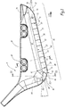
Figure 1 a side view of the active side of a share for uprooting beet crop; -
Figure 2 a side view of the passive side of the share for uprooting beet crop offigure 1 ; -
Figure 3 a cut along line III-III ofFigure 1 ; -
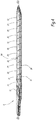
Figure 4 a view of the lower side of the share for uprooting beet crop ofFigure 1 ; -
Figure 5 a cross-cut along line V-V ofFigure 1 and a portion of the support for the share of a harvesting machine; and -
Figure 6 the detail VI ofFigure 5 in greater detail. - On
Figure 5 is shown a portion of aharvesting machine 2, namely anuprooting share 4, ashare support 6 and fixing means 8, in the present case nuts and bolts. - The
harvesting machine 2 is adapted to uproot root crop, in particular beet crop, and specifically sugar beets. Theharvesting machine 2 is as such known from the prior art and is for example of the Terra Dos type by Holmer Maschinenbau. - The
harvesting machine 2 has an uprooting travel direction UTD, which is to the right onFigure 1 . - The
harvesting machine 2 comprises, for each working row of crop to be uprooted, a pair ofuprooting shares 4 which is adapted to push the root crop out of the soil during advancement of the harvesting machine. - Only one
uprooting share 4 is depicted and here below explained. The other uprooting share of the pair of uprooting shares is symmetrical to the uprooting share shown on the Figures with respect to a plane of symmetry parallel to the plane ofFigure 1 and above the plane ofFigure 1 . - The
uprooting share 4 has anactive side 10 adapted to come into contact with the crop to be uprooted and apassive side 12, turned away from the crop to be uprooted. - The
active side 10 forms a closed workingsurface 14 that is generally convex. - The
uprooting share 4 has acutting edge 16 for cutting into the soil and extending along a cutting edge axis CEA. - The uprooting
share 4 comprises abase body 18,basic inserts 20, anupstream end insert 22, adownstream end insert 24 and atransitional insert 26. - The
base body 18 comprises anattachment portion 30 for attachment of the uprooting share to theshare support 6. - The
base body 18 comprises also astep 32 or recess having a shape complementary to the shape of the inserts and adapted to receive the correspondinginserts Figure 6 ). Thestep 32 is formed by aplane surface 34 that is inclined with respect to a corresponding surface of thepassive side 12. Thestep 32 is shaped so that the thickness of the base body diminishes towards the cuttingedge 16. Thestep 32 is also formed by astop surface 36 perpendicular to theplane surface 34 and extending essentially parallel to the cutting edge axis. - The
base body 18 comprises a base body edge face 38 extending along the cutting edge axis CEA. - The uprooting
share 4 comprises in the present case nine of thebasic inserts 20, oneupstream end insert 22, onedownstream end insert 24 and onetransitional insert 26. The inserts form together a set ofinserts 40. All theinserts inserts 40, when placed in succession adjacent one to another and as shown on the Figures form acontinuous guiding surface 42 for guiding root crop on the uprooting share. For forming the guidingsurface 42, thebasic inserts 20 are placed in asuccession 44 adjacent one to another, theupstream end insert 22 is placed at an upstream end of thesuccession 44 and thedownstream end insert 24 is placed at a downstream end of thesuccession 44. - In the present case, the
upstream end insert 22 is placed adjacent abasic insert 20 and thetransitional insert 26 is interposed between the downstream end of thesuccession 44, adjacent abasic insert 20 and adjacent thedownstream end insert 24. Generally, for forming the guidingsurface 42, thetransitional insert 26 can be arranged either between and adjacent to one of thebasic inserts 20 and theupstream end insert 22 or between and adjacent to one of thebasic inserts 20 and thedownstream end insert 24. Thetransitional insert 26 is optional and can be omitted. In this case theupstream end insert 22 and thedownstream end insert 24 are placed adjacent abasic insert 20. - Advantageously, each of the
basic inserts 20 of the set ofinserts 40 is identical. Each of theupstream end insert 22 and thedownstream end insert 24 have a shape different from the shape of thebasic insert 20. Thetransitional insert 26 has a shape different from the shape ofbasic insert 20, theupstream end insert 22 and thedownstream end insert 24. - Each of the
basic inserts 20 has afirst end 50 adapted to form a portion remote from thecutting edge 16 of the uprooting share, and asecond end 52 comprising aninsert edge 54 extending along an insert edge axis IEA and adapted to form at least a portion of thecutting edge 16 of the uprooting share. The thickness of theinsert 20, from thefirst end 50 to thesecond end 52 increases continuously and thesecond end 52 has a thickness T2 greater than a thickness T1 of thefirst end 50. The thickness is generally measured perpendicularly to a plane containing the insert edge axis. - The expression "remote from the cutting edge" is to be understood as opposed to the expression "forming a portion of the cutting edge".
- Each of the
basic inserts 20 has a generating cross section GCS, taken transversally or perpendicularly to the insert edge axis IAE, that is generally polygonal, in particular trapezoidal. In particular, as in the present case, the generating cross section GCS is over its whole circumference strictly convex. Alternatively, the generating cross section GCS could also be over its whole circumference strictly convex, except one single concave section. - Generally, the generating cross section GCS is identical over the whole length L or at least 90% of the length of the
basic insert 20, measured along the insert edge axis IEA, of the insert. - In other words, the outer surface of each the
basic insert 20 comprises afirst side face 56, asecond side face 58, a stop face 60 and anedge face 62. Thefirst side face 56 and thesecond side face 58 are plane faces and are inclined one to another by an angle α preferably comprised between 8° and 12°. Thefirst side face 56 is applied against theplane surface 34. - The stop face 60 and the
edge face 62 are plane faces and are generally parallel one to another. The second side face and theedge face 62 are connected one to another by a fillet. The stop face and the edge face are generally perpendicular to the first side face. - The
basic insert 20 comprises two end faces 64, 66 (Figure 1 ). The end faces 64, 66 are generally planar and in particular parallel one to another. The end faces 64, 66 extend transversally or perpendicularly to the insert edge axis and thus to thefirst side face 56,second side face 58, stop face 60 andedge face 62. - The
basic insert 20 has therefore the general shape of a truncated wedge. - The
upstream end insert 22 has, in a side view, a triangular shape having one arc-shaped edge 70.Theupstream end insert 22 has anend face 72 mating with theend face 66 of the adjacentbasic insert 20 and aface 74 mating with thestop surface 36 of thebase body 18. The faces 72, 74 are preferably perpendicular one to another. - The
downstream end insert 24 has, in a side view, a truncated triangular shape or trapezoidal shape having one arc-shapededge 80. Thedownstream end insert 22 has a anend face 82 mating with the end face 86 (see below) of the adjacenttransitional insert 26 and aface 84 mating with thestop surface 36 of thebase body 18. Theend face 82 and theface 84 are preferably perpendicular one to another. - More particularly, the
stop face 36 is in the present case angled and comprises amain section 361 and adownstream section 362 extending at an angle one to another (seeFigure 1 ). Themain section 361 may be straight and the downstream section may also be straight. In the present case, themain section 361 anddownstream section 362 form angle γ one with another, that is bigger than 0° and preferably comprised between 5° and 30°. Consequently, the most downstream portion of thedownstream end insert 24 is offset away from the cutting edge axis CEA and is subject to little wear. Consequently, thedownstream end insert 24 is not prone to detachment from thebase body 18. - Generally, the
downstream section 361 can be adjacent only thedownstream end insert 24 or also adjacent to the transitional insert(s) 26. - Generally the share can be designed so that at least the
downstream end insert 24 is adjacent and in contact with thedownstream section 362 and at least one basic insert is adjacent and in contact with themain section 361. - The
transitional insert 26 has, in a side view, an essentially trapezoidal shape. Thetransitional insert 26 has anend face 86, adjacent thedownstream end insert 24, and anend face 88, adjacent abasic insert 20. - The
transitional insert 26 has, in a side view, one arc-shapededge 90. The arc-shapededge 90 forms part of thecutting edge 16. - Generally, the uprooting
share 4 has at least one insert fixed to the base body and forming at least a portion of the cutting edge. The insert can be either one of thebasic inserts 20, the upstream end inserts 22 or thedownstream end insert 24, or thetransitional insert 26. Generally, the first end of the insert forms a portion of the insert remote from the cutting edge of the share, and the insert edge forms at least a portion of the cutting edge of the uprooting share. - The base
body edge face 38 and the insert edge face 62 form together a concave profile. This profile is taken for example in a plane transversal or perpendicular to the cutting edge axis CEA and can be seen onfigure 6 . Thebody edge face 38 and the insert edge face 62 are arranged one to another according to an angle β bigger than 0° and at most 40°. Preferably, the angle β is comprised between 5° and 15° and advantageously comprised between 8° and 12°. - This concave profile allows for relatively little wear on the
base body 18 and the inserts, as the edge face of the inserts protects the edge of the base body from contact with soil. Consequently, the transitional zone between the inserts and the base body is not "washed out" by soil. - At least one, preferably more of and particularly each of the
basic inserts 20,upstream end insert 22,downstream end insert 24 andtransitional insert 26 has a surface that is harder than the surface of thebase body 18. The hardness of thebase body 18, at least in a working zone near and adjacent the inserts, is comprised between 45HRC and 52HRC and preferably between 47HRC and 50HRC. - The corresponding insert can have a hardness between 60HRC to 80HRC and more preferably a hardness of 65HRC to 75HRC Each of the inserts is for example manufactures by sintering out of a pressed green body.
- The uprooting
share 4 is manufactured as follows. The or each of thebasic inserts 20, the upstream end inserts 22, thedownstream end insert 24, and optionally thetransitional insert 26 are provided. Thebase body 14 is provided. Then the or each insert is fixed on thebase body 14, in particular by soldering. - The invention relates also to a method of maintenance of a root crop harvesting machine comprising at least two share supports with worn shares. When the shares are worn they need to be replaced. The replacement method is as follows. The worn uprooting shares are unmounted from the share supports. Two replacement uprooting shares, each replacement uprooting share being an uprooting share as disclosed above and being in a state of wear less than the worn uprooting shares are provided. In particular the replacement uprooting shares are new uprooting shares. Finally, the replacement uprooting shares are mounted onto the share supports.
whereby all the inserts of the set of inserts, when placed in succession adjacent one to another are adapted to form a continuous guiding surface for guiding root crop on a share for uprooting root crop, and wherein, for forming the guiding surface, the basic inserts are adapted to be placed in a succession adjacent one to another, the upstream end insert is adapted to be placed at an upstream end of the succession, the downstream end insert is adapted to be placed at a downstream end of the succession.
or
the share has a set of inserts according to any embodiment disclosed herein, the insert being one of the basic inserts of the set of inserts;
and
the first end of the insert forms a portion remote from the cutting edge of the share, and the insert edge forming at least a portion of the cutting edge of the share.
Claims (13)
- Insert (20, 22, 24, 26) for a share for uprooting root crop, the insert having
a first end (50) adapted to form a portion remote from a cutting edge (16) of the share, and a second end (52) comprising an insert edge extending along an insert edge axis (IEA) and adapted to form at least a portion of the cutting edge of the share, characterized in that
the thickness of the insert, from the first end to the second end increases continuously and the second end has a thickness (T2) greater than a thickness (T1) of the first end. - Insert according to claim 1, wherein the insert has a generating cross section (GCS) taken transversally or perpendicularly to the insert edge axis, that is generally polygonal, in particular trapezoidal.
- Insert according to claim 1 or 2, wherein the generating cross section is identical over a whole length (L) or at least over 90% of the length measured along the insert edge axis of the insert and the insert comprises two end faces (64, 66), in particular parallel end faces, extending transversal to the insert edge axis.
- Set of inserts (40) for a share for uprooting crop, the set of inserts comprising:- at least two basic inserts (20) each comprising the features according to any one of claims 1 to 3 and each of the basic inserts being identical,- an upstream end insert (22) and- a downstream end insert (24),whereby each of the upstream end insert and the downstream end insert having a shape different from the shape of basic inserts,
whereby all the inserts of the set of inserts, when placed in succession adjacent one to another are adapted to form a continuous guiding surface (42) for guiding root crop on a share for uprooting root crop, and wherein, for forming the guiding surface, the basic inserts are adapted to be placed in a succession adjacent one to another, the upstream end insert is adapted to be placed at an upstream end of the succession, the downstream end insert is adapted to be placed at a downstream end of the succession. - Set of inserts (40) for a share for uprooting crop according to claim 4, wherein
the upstream end insert (22) and/or the downstream end insert (24), has/have a trapezoidal or triangular shape having one arc-shape edge (70, 80). - Set of inserts for a share for uprooting crop according to claim 4 or 5, wherein
the set of inserts comprises at least one transitional insert (26) having a shape different from the shape of the basic insert, the shape of the upstream end insert and the shape of the downstream end insert, and wherein
for forming the guiding surface, the transitional insert is adapted to be arranged between either one of the basic inserts and the upstream end insert or between one of the basic inserts and the downstream end insert. - Set of inserts for a share for uprooting crop according to claim 6, wherein the transitional insert (26) has, in a side view, an essentially trapezoidal shape.
- Share for uprooting crop, in particular beet crop,
the share having a cutting edge (16) for cutting in the soil, the cutting edge extending along a cutting edge axis (CEA),
the share comprising:- a base body, which comprises an attachment portion (30) adapted to attach the share to a support (6) of a harvesting machine,- at least one insert (20, 22, 24, 26) fixed to the base body and forming at least a portion of the cutting edge, characterized in thateither
the insert is an insert according to any one of claims 1 to 3,
or
the share has a set of inserts according to any one of claims 4 to 7, the insert being one of the basic inserts (20) of the set of inserts;
and
the first end of the insert forms a portion remote from the cutting edge (16) of the share, and the insert edge (54) forming at least a portion of the cutting edge of the share. - Share for uprooting crop according to claim 8, wherein- the base body comprises a base body edge face (38),- the insert comprises an insert edge face (62),- the base body edge face and the insert edge face form together a convex profile.
- Share according to any one of claims 8 or 9, wherein the or each insert (20, 22, 24, 26) comprises a surface that is harder than a surface of the base body, in particular the or each insert having a hardness between 60HRC and 80HRC and preferably between 65HRC and 75HRC.
- Share according to any one of claims 8 to 10, wherein the base body comprises
a stop face (36), the stop face (36) being angled and comprising a main section (361) and a downstream section (362) extending at an angle one to another;
and at least the downstream end insert (24) being adjacent and in contact with the downstream section (362) and at least one basic insert being adjacent and in contact with the main section (361). - Method of manufacture of a share according to at least claim 8, comprising the steps of:- providing the or each insert (20, 22, 24, 26);- providing the base body (18), and- fixing the or each insert on the base body, in particular by soldering.
- Method of maintenance of a root crop harvesting machine comprising at least two share supports with worn uprooting shares, comprising the steps of:- unmounting of the worn uprooting shares from the share supports;- providing at least two replacement uprooting shares (4), each replacement uprooting share being a share according to one of claims 8 to 11 and being in a state of wear less than the worn shares;- mounting the replacement uprooting shares onto the share supports.
Priority Applications (4)
| Application Number | Priority Date | Filing Date | Title |
|---|---|---|---|
| EP18306381.7A EP3643156B1 (en) | 2018-10-23 | 2018-10-23 | Insert for a share for uprooting root crop, corresponding set of inserts, share and methods of manufacture and maintenance |
| CN201910950565.9A CN111083984A (en) | 2018-10-23 | 2019-10-08 | Root crop hoe blade, blade set, hoe blade and manufacturing and maintaining method thereof |
| RU2019133022A RU2019133022A (en) | 2018-10-23 | 2019-10-18 | Root digging opener insert, matching insert set, opener and how to make and maintain it |
| US16/660,288 US20200120850A1 (en) | 2018-10-23 | 2019-10-22 | Insert for a Share for Uprooting Root Crop, Corresponding Set of Inserts, Share and Methods of Manufacture and Maintenance |
Applications Claiming Priority (1)
| Application Number | Priority Date | Filing Date | Title |
|---|---|---|---|
| EP18306381.7A EP3643156B1 (en) | 2018-10-23 | 2018-10-23 | Insert for a share for uprooting root crop, corresponding set of inserts, share and methods of manufacture and maintenance |
Publications (2)
| Publication Number | Publication Date |
|---|---|
| EP3643156A1 true EP3643156A1 (en) | 2020-04-29 |
| EP3643156B1 EP3643156B1 (en) | 2021-11-24 |
Family
ID=64083042
Family Applications (1)
| Application Number | Title | Priority Date | Filing Date |
|---|---|---|---|
| EP18306381.7A Active EP3643156B1 (en) | 2018-10-23 | 2018-10-23 | Insert for a share for uprooting root crop, corresponding set of inserts, share and methods of manufacture and maintenance |
Country Status (4)
| Country | Link |
|---|---|
| US (1) | US20200120850A1 (en) |
| EP (1) | EP3643156B1 (en) |
| CN (1) | CN111083984A (en) |
| RU (1) | RU2019133022A (en) |
Citations (5)
| Publication number | Priority date | Publication date | Assignee | Title |
|---|---|---|---|---|
| US1169229A (en) * | 1915-07-24 | 1916-01-25 | Alfred G Bimson | Beet-harvester. |
| DE10218778A1 (en) * | 2002-04-26 | 2003-11-13 | Rieter Werke Haendle | Scraper used in comminuting mill for cleaning roller is mounted on pivoted brackets and has hydraulic or pneumatic cylinders pressing blade onto roller |
| DE102013104836A1 (en) | 2013-05-10 | 2014-11-13 | Betek Gmbh & Co. Kg | Rübenrodeschar |
| WO2015165934A1 (en) * | 2014-04-30 | 2015-11-05 | Sandvik Intellectual Property Ab | A wear resistant component and a device for mechanical decomposition of material provided with such a component |
| DE102017210780B3 (en) * | 2017-06-27 | 2018-05-17 | Thyssenkrupp Ag | Breaking tool and method for producing a breaking tool |
Family Cites Families (10)
| Publication number | Priority date | Publication date | Assignee | Title |
|---|---|---|---|---|
| US4715450A (en) * | 1987-02-20 | 1987-12-29 | Kennametal Inc. | Grader blade with casting/insert assembly on leading edge |
| SU1729320A1 (en) * | 1990-07-09 | 1992-04-30 | Киевский Политехнический Институт Им.50-Летия Великой Октябрьской Социалистической Революции | Ripping working organ |
| US5159985A (en) * | 1991-02-06 | 1992-11-03 | Kennametal Inc. | Agricultural insert |
| US6003617A (en) * | 1998-02-09 | 1999-12-21 | Larry J. McSweeney | Insert for board |
| CN101238771A (en) * | 2008-03-07 | 2008-08-13 | 东北农业大学 | Profile Loosening Shovel |
| DE102009029894B4 (en) * | 2009-06-23 | 2019-03-21 | Betek Gmbh & Co. Kg | Tillage tool |
| DE202010008085U1 (en) * | 2010-07-15 | 2011-10-21 | Betek Bergbau- Und Hartmetalltechnik Karl-Heinz Simon Gmbh & Co. Kg | Tillage tool |
| WO2013106930A1 (en) * | 2012-01-18 | 2013-07-25 | Macdon Industries Ltd. | Sickle guard shape for use in a sickle cutter system with increased ground speed |
| DE102015122620B4 (en) * | 2014-12-22 | 2025-05-28 | Betek Gmbh & Co. Kg | tool system |
| CN205812789U (en) * | 2016-06-17 | 2016-12-21 | 福建农林大学 | Cropper digger blade |
-
2018
- 2018-10-23 EP EP18306381.7A patent/EP3643156B1/en active Active
-
2019
- 2019-10-08 CN CN201910950565.9A patent/CN111083984A/en active Pending
- 2019-10-18 RU RU2019133022A patent/RU2019133022A/en unknown
- 2019-10-22 US US16/660,288 patent/US20200120850A1/en not_active Abandoned
Patent Citations (5)
| Publication number | Priority date | Publication date | Assignee | Title |
|---|---|---|---|---|
| US1169229A (en) * | 1915-07-24 | 1916-01-25 | Alfred G Bimson | Beet-harvester. |
| DE10218778A1 (en) * | 2002-04-26 | 2003-11-13 | Rieter Werke Haendle | Scraper used in comminuting mill for cleaning roller is mounted on pivoted brackets and has hydraulic or pneumatic cylinders pressing blade onto roller |
| DE102013104836A1 (en) | 2013-05-10 | 2014-11-13 | Betek Gmbh & Co. Kg | Rübenrodeschar |
| WO2015165934A1 (en) * | 2014-04-30 | 2015-11-05 | Sandvik Intellectual Property Ab | A wear resistant component and a device for mechanical decomposition of material provided with such a component |
| DE102017210780B3 (en) * | 2017-06-27 | 2018-05-17 | Thyssenkrupp Ag | Breaking tool and method for producing a breaking tool |
Also Published As
| Publication number | Publication date |
|---|---|
| EP3643156B1 (en) | 2021-11-24 |
| US20200120850A1 (en) | 2020-04-23 |
| CN111083984A (en) | 2020-05-01 |
| RU2019133022A (en) | 2021-04-19 |
Similar Documents
| Publication | Publication Date | Title |
|---|---|---|
| US10646880B2 (en) | Cutting tooth splitter apparatus and method | |
| US2619787A (en) | Sickle guard | |
| US6543211B1 (en) | Crop harvesting header with angle adjustment of the knife guards | |
| CN102802399A (en) | Soil treating tool | |
| US20170367248A1 (en) | Guide element and tool combination comprising a guide element | |
| EP3756442B1 (en) | Shearbar | |
| US8590355B2 (en) | Chopping blade and counterblade for a chopping device and process for its production | |
| EA028297B1 (en) | Sickle knife cutter for harvesting crop with a quick release knife section | |
| US10668547B2 (en) | Saw blade for a saw cutting stalk crops | |
| EP3165060B1 (en) | Improved rotary harrow tool and harrow comprising such tools | |
| EP3643156B1 (en) | Insert for a share for uprooting root crop, corresponding set of inserts, share and methods of manufacture and maintenance | |
| EP3701778B1 (en) | Working tool, especially soil working tool | |
| EP1305992A1 (en) | Crop harvesting header with angle adjustment of the knife guards | |
| SE1650815A1 (en) | Plate tools, agricultural implements including such plating tools and process for the manufacture of plating tools | |
| US9820432B2 (en) | Beet puller share | |
| US10736277B2 (en) | Curved delimbing blade, use of same, corresponding delimbing head and cutting kit | |
| US5482120A (en) | Method and apparatus for removing plant stalks | |
| US5596811A (en) | Chainsaw guide bar | |
| CN213695690U (en) | Threshing knife | |
| US4338954A (en) | Combine cylinder reel tooth | |
| US11167443B2 (en) | Feed roller assembly | |
| CN112806147A (en) | Root crop harvesting device and corresponding method | |
| CN105900600A (en) | Conveying combing wheel | |
| AU2020403919B2 (en) | Wear part, bucket and method | |
| US20230380343A1 (en) | Brush cutter rotor |
Legal Events
| Date | Code | Title | Description |
|---|---|---|---|
| PUAI | Public reference made under article 153(3) epc to a published international application that has entered the european phase |
Free format text: ORIGINAL CODE: 0009012 |
|
| STAA | Information on the status of an ep patent application or granted ep patent |
Free format text: STATUS: THE APPLICATION HAS BEEN PUBLISHED |
|
| AK | Designated contracting states |
Kind code of ref document: A1 Designated state(s): AL AT BE BG CH CY CZ DE DK EE ES FI FR GB GR HR HU IE IS IT LI LT LU LV MC MK MT NL NO PL PT RO RS SE SI SK SM TR |
|
| AX | Request for extension of the european patent |
Extension state: BA ME |
|
| STAA | Information on the status of an ep patent application or granted ep patent |
Free format text: STATUS: REQUEST FOR EXAMINATION WAS MADE |
|
| 17P | Request for examination filed |
Effective date: 20201023 |
|
| RBV | Designated contracting states (corrected) |
Designated state(s): AL AT BE BG CH CY CZ DE DK EE ES FI FR GB GR HR HU IE IS IT LI LT LU LV MC MK MT NL NO PL PT RO RS SE SI SK SM TR |
|
| STAA | Information on the status of an ep patent application or granted ep patent |
Free format text: STATUS: EXAMINATION IS IN PROGRESS |
|
| 17Q | First examination report despatched |
Effective date: 20201216 |
|
| GRAP | Despatch of communication of intention to grant a patent |
Free format text: ORIGINAL CODE: EPIDOSNIGR1 |
|
| STAA | Information on the status of an ep patent application or granted ep patent |
Free format text: STATUS: GRANT OF PATENT IS INTENDED |
|
| INTG | Intention to grant announced |
Effective date: 20210618 |
|
| RIN1 | Information on inventor provided before grant (corrected) |
Inventor name: RICHTER, EDUARD Inventor name: THE OTHER INVENTOR HAS WAIVED HIS RIGHT TO BE THUS MENTIONED. |
|
| GRAS | Grant fee paid |
Free format text: ORIGINAL CODE: EPIDOSNIGR3 |
|
| GRAA | (expected) grant |
Free format text: ORIGINAL CODE: 0009210 |
|
| STAA | Information on the status of an ep patent application or granted ep patent |
Free format text: STATUS: THE PATENT HAS BEEN GRANTED |
|
| AK | Designated contracting states |
Kind code of ref document: B1 Designated state(s): AL AT BE BG CH CY CZ DE DK EE ES FI FR GB GR HR HU IE IS IT LI LT LU LV MC MK MT NL NO PL PT RO RS SE SI SK SM TR |
|
| REG | Reference to a national code |
Ref country code: GB Ref legal event code: FG4D |
|
| REG | Reference to a national code |
Ref country code: AT Ref legal event code: REF Ref document number: 1449117 Country of ref document: AT Kind code of ref document: T Effective date: 20211215 |
|
| REG | Reference to a national code |
Ref country code: DE Ref legal event code: R096 Ref document number: 602018027096 Country of ref document: DE |
|
| REG | Reference to a national code |
Ref country code: IE Ref legal event code: FG4D |
|
| REG | Reference to a national code |
Ref country code: NL Ref legal event code: FP |
|
| REG | Reference to a national code |
Ref country code: LT Ref legal event code: MG9D |
|
| REG | Reference to a national code |
Ref country code: AT Ref legal event code: MK05 Ref document number: 1449117 Country of ref document: AT Kind code of ref document: T Effective date: 20211124 |
|
| PG25 | Lapsed in a contracting state [announced via postgrant information from national office to epo] |
Ref country code: RS Free format text: LAPSE BECAUSE OF FAILURE TO SUBMIT A TRANSLATION OF THE DESCRIPTION OR TO PAY THE FEE WITHIN THE PRESCRIBED TIME-LIMIT Effective date: 20211124 Ref country code: LT Free format text: LAPSE BECAUSE OF FAILURE TO SUBMIT A TRANSLATION OF THE DESCRIPTION OR TO PAY THE FEE WITHIN THE PRESCRIBED TIME-LIMIT Effective date: 20211124 Ref country code: FI Free format text: LAPSE BECAUSE OF FAILURE TO SUBMIT A TRANSLATION OF THE DESCRIPTION OR TO PAY THE FEE WITHIN THE PRESCRIBED TIME-LIMIT Effective date: 20211124 Ref country code: BG Free format text: LAPSE BECAUSE OF FAILURE TO SUBMIT A TRANSLATION OF THE DESCRIPTION OR TO PAY THE FEE WITHIN THE PRESCRIBED TIME-LIMIT Effective date: 20220224 Ref country code: AT Free format text: LAPSE BECAUSE OF FAILURE TO SUBMIT A TRANSLATION OF THE DESCRIPTION OR TO PAY THE FEE WITHIN THE PRESCRIBED TIME-LIMIT Effective date: 20211124 |
|
| PG25 | Lapsed in a contracting state [announced via postgrant information from national office to epo] |
Ref country code: IS Free format text: LAPSE BECAUSE OF FAILURE TO SUBMIT A TRANSLATION OF THE DESCRIPTION OR TO PAY THE FEE WITHIN THE PRESCRIBED TIME-LIMIT Effective date: 20220324 Ref country code: SE Free format text: LAPSE BECAUSE OF FAILURE TO SUBMIT A TRANSLATION OF THE DESCRIPTION OR TO PAY THE FEE WITHIN THE PRESCRIBED TIME-LIMIT Effective date: 20211124 Ref country code: PT Free format text: LAPSE BECAUSE OF FAILURE TO SUBMIT A TRANSLATION OF THE DESCRIPTION OR TO PAY THE FEE WITHIN THE PRESCRIBED TIME-LIMIT Effective date: 20220324 Ref country code: PL Free format text: LAPSE BECAUSE OF FAILURE TO SUBMIT A TRANSLATION OF THE DESCRIPTION OR TO PAY THE FEE WITHIN THE PRESCRIBED TIME-LIMIT Effective date: 20211124 Ref country code: NO Free format text: LAPSE BECAUSE OF FAILURE TO SUBMIT A TRANSLATION OF THE DESCRIPTION OR TO PAY THE FEE WITHIN THE PRESCRIBED TIME-LIMIT Effective date: 20220224 Ref country code: LV Free format text: LAPSE BECAUSE OF FAILURE TO SUBMIT A TRANSLATION OF THE DESCRIPTION OR TO PAY THE FEE WITHIN THE PRESCRIBED TIME-LIMIT Effective date: 20211124 Ref country code: HR Free format text: LAPSE BECAUSE OF FAILURE TO SUBMIT A TRANSLATION OF THE DESCRIPTION OR TO PAY THE FEE WITHIN THE PRESCRIBED TIME-LIMIT Effective date: 20211124 Ref country code: ES Free format text: LAPSE BECAUSE OF FAILURE TO SUBMIT A TRANSLATION OF THE DESCRIPTION OR TO PAY THE FEE WITHIN THE PRESCRIBED TIME-LIMIT Effective date: 20211124 |
|
| PG25 | Lapsed in a contracting state [announced via postgrant information from national office to epo] |
Ref country code: SM Free format text: LAPSE BECAUSE OF FAILURE TO SUBMIT A TRANSLATION OF THE DESCRIPTION OR TO PAY THE FEE WITHIN THE PRESCRIBED TIME-LIMIT Effective date: 20211124 Ref country code: SK Free format text: LAPSE BECAUSE OF FAILURE TO SUBMIT A TRANSLATION OF THE DESCRIPTION OR TO PAY THE FEE WITHIN THE PRESCRIBED TIME-LIMIT Effective date: 20211124 Ref country code: RO Free format text: LAPSE BECAUSE OF FAILURE TO SUBMIT A TRANSLATION OF THE DESCRIPTION OR TO PAY THE FEE WITHIN THE PRESCRIBED TIME-LIMIT Effective date: 20211124 Ref country code: EE Free format text: LAPSE BECAUSE OF FAILURE TO SUBMIT A TRANSLATION OF THE DESCRIPTION OR TO PAY THE FEE WITHIN THE PRESCRIBED TIME-LIMIT Effective date: 20211124 Ref country code: DK Free format text: LAPSE BECAUSE OF FAILURE TO SUBMIT A TRANSLATION OF THE DESCRIPTION OR TO PAY THE FEE WITHIN THE PRESCRIBED TIME-LIMIT Effective date: 20211124 Ref country code: CZ Free format text: LAPSE BECAUSE OF FAILURE TO SUBMIT A TRANSLATION OF THE DESCRIPTION OR TO PAY THE FEE WITHIN THE PRESCRIBED TIME-LIMIT Effective date: 20211124 |
|
| REG | Reference to a national code |
Ref country code: DE Ref legal event code: R097 Ref document number: 602018027096 Country of ref document: DE |
|
| PLBE | No opposition filed within time limit |
Free format text: ORIGINAL CODE: 0009261 |
|
| STAA | Information on the status of an ep patent application or granted ep patent |
Free format text: STATUS: NO OPPOSITION FILED WITHIN TIME LIMIT |
|
| PG25 | Lapsed in a contracting state [announced via postgrant information from national office to epo] |
Ref country code: AL Free format text: LAPSE BECAUSE OF FAILURE TO SUBMIT A TRANSLATION OF THE DESCRIPTION OR TO PAY THE FEE WITHIN THE PRESCRIBED TIME-LIMIT Effective date: 20211124 |
|
| 26N | No opposition filed |
Effective date: 20220825 |
|
| PG25 | Lapsed in a contracting state [announced via postgrant information from national office to epo] |
Ref country code: SI Free format text: LAPSE BECAUSE OF FAILURE TO SUBMIT A TRANSLATION OF THE DESCRIPTION OR TO PAY THE FEE WITHIN THE PRESCRIBED TIME-LIMIT Effective date: 20211124 |
|
| PG25 | Lapsed in a contracting state [announced via postgrant information from national office to epo] |
Ref country code: MC Free format text: LAPSE BECAUSE OF FAILURE TO SUBMIT A TRANSLATION OF THE DESCRIPTION OR TO PAY THE FEE WITHIN THE PRESCRIBED TIME-LIMIT Effective date: 20211124 Ref country code: IT Free format text: LAPSE BECAUSE OF FAILURE TO SUBMIT A TRANSLATION OF THE DESCRIPTION OR TO PAY THE FEE WITHIN THE PRESCRIBED TIME-LIMIT Effective date: 20211124 |
|
| REG | Reference to a national code |
Ref country code: CH Ref legal event code: PL |
|
| REG | Reference to a national code |
Ref country code: BE Ref legal event code: MM Effective date: 20221031 |
|
| GBPC | Gb: european patent ceased through non-payment of renewal fee |
Effective date: 20221023 |
|
| PG25 | Lapsed in a contracting state [announced via postgrant information from national office to epo] |
Ref country code: LU Free format text: LAPSE BECAUSE OF NON-PAYMENT OF DUE FEES Effective date: 20221023 |
|
| PG25 | Lapsed in a contracting state [announced via postgrant information from national office to epo] |
Ref country code: LI Free format text: LAPSE BECAUSE OF NON-PAYMENT OF DUE FEES Effective date: 20221031 Ref country code: CH Free format text: LAPSE BECAUSE OF NON-PAYMENT OF DUE FEES Effective date: 20221031 |
|
| PG25 | Lapsed in a contracting state [announced via postgrant information from national office to epo] |
Ref country code: BE Free format text: LAPSE BECAUSE OF NON-PAYMENT OF DUE FEES Effective date: 20221031 |
|
| PG25 | Lapsed in a contracting state [announced via postgrant information from national office to epo] |
Ref country code: IE Free format text: LAPSE BECAUSE OF NON-PAYMENT OF DUE FEES Effective date: 20221023 Ref country code: GB Free format text: LAPSE BECAUSE OF NON-PAYMENT OF DUE FEES Effective date: 20221023 |
|
| PG25 | Lapsed in a contracting state [announced via postgrant information from national office to epo] |
Ref country code: HU Free format text: LAPSE BECAUSE OF FAILURE TO SUBMIT A TRANSLATION OF THE DESCRIPTION OR TO PAY THE FEE WITHIN THE PRESCRIBED TIME-LIMIT; INVALID AB INITIO Effective date: 20181023 |
|
| PG25 | Lapsed in a contracting state [announced via postgrant information from national office to epo] |
Ref country code: CY Free format text: LAPSE BECAUSE OF FAILURE TO SUBMIT A TRANSLATION OF THE DESCRIPTION OR TO PAY THE FEE WITHIN THE PRESCRIBED TIME-LIMIT Effective date: 20211124 |
|
| PG25 | Lapsed in a contracting state [announced via postgrant information from national office to epo] |
Ref country code: MK Free format text: LAPSE BECAUSE OF FAILURE TO SUBMIT A TRANSLATION OF THE DESCRIPTION OR TO PAY THE FEE WITHIN THE PRESCRIBED TIME-LIMIT Effective date: 20211124 |
|
| PG25 | Lapsed in a contracting state [announced via postgrant information from national office to epo] |
Ref country code: MT Free format text: LAPSE BECAUSE OF FAILURE TO SUBMIT A TRANSLATION OF THE DESCRIPTION OR TO PAY THE FEE WITHIN THE PRESCRIBED TIME-LIMIT Effective date: 20211124 |
|
| PG25 | Lapsed in a contracting state [announced via postgrant information from national office to epo] |
Ref country code: GR Free format text: LAPSE BECAUSE OF NON-PAYMENT OF DUE FEES Effective date: 20211124 |
|
| PG25 | Lapsed in a contracting state [announced via postgrant information from national office to epo] |
Ref country code: GR Free format text: LAPSE BECAUSE OF NON-PAYMENT OF DUE FEES Effective date: 20211124 |
|
| PGFP | Annual fee paid to national office [announced via postgrant information from national office to epo] |
Ref country code: NL Payment date: 20250926 Year of fee payment: 8 |
|
| PGFP | Annual fee paid to national office [announced via postgrant information from national office to epo] |
Ref country code: DE Payment date: 20251015 Year of fee payment: 8 |
|
| PGFP | Annual fee paid to national office [announced via postgrant information from national office to epo] |
Ref country code: FR Payment date: 20251027 Year of fee payment: 8 |