EP3642922B1 - Telecommunications enclosure and related components - Google Patents
Telecommunications enclosure and related components Download PDFInfo
- Publication number
- EP3642922B1 EP3642922B1 EP18733602.9A EP18733602A EP3642922B1 EP 3642922 B1 EP3642922 B1 EP 3642922B1 EP 18733602 A EP18733602 A EP 18733602A EP 3642922 B1 EP3642922 B1 EP 3642922B1
- Authority
- EP
- European Patent Office
- Prior art keywords
- gel
- gel sealing
- block
- pressurization
- base
- Prior art date
- Legal status (The legal status is an assumption and is not a legal conclusion. Google has not performed a legal analysis and makes no representation as to the accuracy of the status listed.)
- Active
Links
Images
































Classifications
-
- G—PHYSICS
- G02—OPTICS
- G02B—OPTICAL ELEMENTS, SYSTEMS OR APPARATUS
- G02B6/00—Light guides; Structural details of arrangements comprising light guides and other optical elements, e.g. couplings
- G02B6/44—Mechanical structures for providing tensile strength and external protection for fibres, e.g. optical transmission cables
- G02B6/4439—Auxiliary devices
- G02B6/444—Systems or boxes with surplus lengths
- G02B6/4441—Boxes
- G02B6/4442—Cap coupling boxes
- G02B6/4444—Seals
-
- G—PHYSICS
- G02—OPTICS
- G02B—OPTICAL ELEMENTS, SYSTEMS OR APPARATUS
- G02B6/00—Light guides; Structural details of arrangements comprising light guides and other optical elements, e.g. couplings
- G02B6/44—Mechanical structures for providing tensile strength and external protection for fibres, e.g. optical transmission cables
- G02B6/4439—Auxiliary devices
- G02B6/444—Systems or boxes with surplus lengths
- G02B6/4441—Boxes
- G02B6/4446—Cable boxes, e.g. splicing boxes with two or more multi fibre cables
-
- G—PHYSICS
- G02—OPTICS
- G02B—OPTICAL ELEMENTS, SYSTEMS OR APPARATUS
- G02B6/00—Light guides; Structural details of arrangements comprising light guides and other optical elements, e.g. couplings
- G02B6/44—Mechanical structures for providing tensile strength and external protection for fibres, e.g. optical transmission cables
- G02B6/4439—Auxiliary devices
- G02B6/444—Systems or boxes with surplus lengths
- G02B6/4441—Boxes
- G02B6/4446—Cable boxes, e.g. splicing boxes with two or more multi fibre cables
- G02B6/44465—Seals
-
- G—PHYSICS
- G02—OPTICS
- G02B—OPTICAL ELEMENTS, SYSTEMS OR APPARATUS
- G02B6/00—Light guides; Structural details of arrangements comprising light guides and other optical elements, e.g. couplings
- G02B6/44—Mechanical structures for providing tensile strength and external protection for fibres, e.g. optical transmission cables
- G02B6/4439—Auxiliary devices
- G02B6/4471—Terminating devices ; Cable clamps
- G02B6/44775—Cable seals e.g. feed-through
-
- H—ELECTRICITY
- H02—GENERATION; CONVERSION OR DISTRIBUTION OF ELECTRIC POWER
- H02G—INSTALLATION OF ELECTRIC CABLES OR LINES, OR OF COMBINED OPTICAL AND ELECTRIC CABLES OR LINES
- H02G15/00—Cable fittings
- H02G15/013—Sealing means for cable inlets
Definitions
- the present disclosure relates generally to sealed telecommunications enclosures.
- Telecommunications systems typically employ a network of telecommunications cables capable of transmitting large volumes of data and voice signals over relatively long distances.
- the telecommunications cables can include fiber optic cables, electrical cables, or combinations of electrical and fiber optic cables.
- a typical telecommunications network also includes a plurality of telecommunications enclosures integrated throughout the network of telecommunications cables. The telecommunications enclosures are adapted to house and protect telecommunications components such as splices, termination panels, power splitters and wavelength division multiplexers.
- the telecommunications enclosures can be re-enterable.
- re-enterable means that the telecommunications enclosures can be reopened to allow access to the telecommunications components housed therein without requiring the removal and destruction of the telecommunications enclosures.
- certain telecommunications enclosures can include separate access panels that can be opened to access the interiors of the enclosures, and then closed to re-seal the enclosures.
- Other telecommunications enclosures take the form of elongated sleeves formed by wrap-around covers or half-shells having longitudinal edges that are joined by clamps or other retainers.
- Still other telecommunications enclosures include two half-pieces that are joined together through clamps, wedges or other structures.
- Telecommunications enclosures are typically sealed to inhibit the intrusion of moisture or other contaminants.
- Pressurized gel-type seals have been used to effectively seal the locations where telecommunications cables enter and exit telecommunications enclosures.
- Example pressurized gel-type seals are disclosed by document EP 0442941 B1 and document EP 0587616 B 1 . Both of these documents disclose gel-type cable seals that are pressurized through the use of threaded actuators.
- Document US 6,046,406 discloses a cable seal that is pressurized through the use of an actuator including a cam lever.
- PCT Patent Publication Nos. WO 2014/095462 and WO 2014/005916 disclose enclosures having gel blocks with individually removable gel sealing modules. While pressurized cable seals have generally proven to be effective, improvements in this area are still needed.
- Patent publications - WO 2014/005918 A2 and WO 2014/005919 A2 - disclose relevant background information that may be useful for understanding the present invention.
- One aspect of the present disclosure relates to an enclosure having a sealing unit with a gel block capable of being placed under tension to facilitate removal of the gel block from the enclosure.
- Another aspect of the present disclosure relates to a method for removing a gel block from a gel-block mounting sleeve of a housing.
- the gel block is moved along an axis relative to the gel-block mounting sleeve during removal of the gel block from the gel-block mounting sleeve.
- the method includes placing the gel block in axial tension along the axis while the gel block is in the gel-block mounting sleeve to at least partially break or reduce adhesion between a radially outwardly facing surface of the gel and a radially inwardly facing surface of the gel-block mounting sleeve.
- the method also includes removing the gel block from the gel-block mounting sleeve by moving the gel block along the axis relative to the gel-block mounting sleeve after the gel has been placed in tension.
- the gel can be maintained in tension as the gel block is removed from the gel-block mounting sleeve.
- the gel can be placed in tension by an actuator that is also used to apply axial compressive load to the gel to enhance sealing of the gel within the gel-block mounting sleeve.
- the actuator can include at least one spring or a plurality of springs for applying axial compressive load to the gel in the form of compressive spring pressure.
- the gel can define at least one axially extending cable sealing port. In any of the above examples, the gel can define a plurality of axially extending cable ports. In any of the above examples, the gel block can include a plurality of individual gel sealing modules that cooperate to define the gel block. In any of the above examples, the actuator can include inner and outer pressurization structures between which the gel block is pressurized during sealing. In any of the above examples, the gel sealing modules can be attached to inner and outer pressurization structures of an actuator by snap-fit connections capable of transferring tensile load from the pressurization structures to the gel sealing modules. In certain examples, the snap-fit connections can be made by snap-fit interface components which snap together in an axial orientation.
- the snap-fit interface components can include posts and snap-fit collars.
- the gel sealing modules are individually and separately removable from between inner and outer pressurization structures and at least a plurality of their removable gel sealing modules are cable sealing modules each including: at least first and second gel portions that meet at a separable interface at which at least one cable port is defined, the first and second gel portions being capable of being separated from one another when the cable sealing module is not between the inner and outer pressurization structures to allow a cable to be inserted laterally into the cable port; and end caps between which cable ports extend, end caps each including first end cap portions attached to opposite ends of the first gel portion and second end cap portions attached to opposite ends of the second gel portion, the first and second end cap portions separating from one another when the first and second gel portions are separated from one another.
- living hinges or other flexible connections can be used to interconnect the separate portions of the cable sealing modules.
- the cable sealing module includes at least first and second gel portions that meet at a separable interface at which at least one cable port is defined. First and second gel portions are capable of being separated from one another when the cable sealing module is not between the pressurization structures to allow a cable to be laterally inserted into the cable port.
- the cable sealing module also includes end caps between which an axis of the cable port extends. The end caps each include first end cap portions attached to opposite ends of the first gel portion and second end cap portions attached to opposite ends of the second gel portion. The first and second end cap portions separate from one another when the first and second gel portions are separated from one another.
- the cable sealing module also includes snap-fit structures integrated with the end caps for coupling in a snap-fit connection with the pressurization structures of the actuator.
- the snap-fit structures can include posts or collars.
- the snap-fit structures can include posts having enlarged heads, posts projection outwardly from the end caps in an orientation parallel to the axis of the cable port.
- the separable portions of the cable sealing module can be coupled together by a living hinge their flexible means that allows the portions to be separated from one another at the separable interface while preventing the separable portions from being completely detached from one another.
- the separable portions of the cable sealing modules can be completely detachable from one another.
- the present invention relates to an enclosure including a housing including a gel-block mounting sleeve.
- the enclosure also includes a gel sealing unit including: a gel sealing block that mounts within the gel-block mounting sleeve; and an actuator capable of applying compressive load to the gel sealing block during sealing, and capable of applying tensile load to the gel sealing block to facilitate removal of the gel sealing block from the gel-block mounting sleeve.
- the actuator includes at least one spring for applying the compressive load to the gel sealing block in the form of compressive spring pressure.
- the actuator includes pressurization structures between which the gel seal block mounts, wherein the gel sealing block is pressurized between the pressurization structures during sealing, when the gel sealing block is coupled to the pressurization structures by a coupled interface that allows the pressurization structures to apply tension to the gel sealing block prior to removal of the gel sealing block from the gel-block mounting sleeve, and wherein during tensioning positioning of the pressurization structure is absolutely controlled by a trigger arrangement of the actuator without influence from the at least one spring.
- the trigger arrangement can apply compressive load for forcing the pressurization structures together through at least one spring and can positively engage the pressurization structures during tensioning such that axial movement of a threaded component of the trigger arrangement is converted into an equal axial increase in a spacing between the pressurization structures.
- the trigger arrangement can engage a positive stop corresponding to at least one of the pressurization structures to provide positive movement of the pressurization structures during tensioning after the one or more springs have been de-compressed.
- the gel block can include a plurality of individual gel sealing modules that cooperate to define the gel block.
- the gel sealing modules can be attached to the inner and outer pressurization structures by snap-fit connections capable of transferring tensile load from the pressurization structures to the gel sealing modules.
- the snap-fit connections are made by snap-fit interface components which snap together in an axial orientation.
- the snap-fit interface components can include posts and snap-fit collars.
- the gel sealing modules can be individually and separately removable from between the pressurization structures and at least the plurality of the removable gel sealing modules are cable sealing modules each including: at least first and second gel portions that meet at a separable interface which at least one cable port is defined, the first and second gel portions being capable of being separated from one another when the cable sealing module is not between the pressurization structures to allow a cable to be laterally inserted into the cable port; and end caps between which the cable port extends, the end caps each including first end cap portions attached to opposite ends of the first gel portion and second end cap portions attached to opposite ends of the second gel portion, the first and second end cap portions separating from one another when the first and second gel portions are separated from one another.
- the end caps can include snap-fit structures for coupling in a snap-fit connection with the pressurization structures.
- the housing can include a dome coupled to a base, wherein the gel-block mounting sleeve is defined within the base.
- the base can include a first end that couples to the dome and an opposite second end, and the gel sealing block can be inserted into the gel-block mounting sleeve through the second end of the base.
- the pressurization structures can include inner and outer pressurization structures, wherein the inner pressurization structures coupled to an anchoring bracket that is carried with the inner pressurization structure when the gel sealing block is inserted into and remove from the base, wherein the anchoring bracket can be axially inserted into the base with the gel sealing block when in a first rotational position relative to the base, and wherein once the gel sealing block and the anchoring bracket have been inserted into the base, the gel sealing block and the anchoring bracket can be rotated relative to the base to a second rotational position where the anchoring bracket is axially affixed within the base.
- the anchoring bracket is prevented from rotating from the second rotational position back to the first rotational position by a fastener, a snap-fit structure, a clip, a latch, a slide latch, or other structure.
- a further aspect of the present disclosure relates to an enclosure having a housing including a dome coupled to a base.
- the base includes a first end that couples to the dome and an opposite second end.
- the base defines a gel-block mounting sleeve.
- the enclosure also includes a gel sealing unit including a gel sealing block that mounts within the gel-block mounting sleeve by inserting the gel block through the second end of the base.
- the enclosure further includes an actuator capable of applying compressive load to the gel sealing block during sealing.
- the actuator includes inner and outer pressurization structures between which the gel sealing block mounts.
- the inner pressurization structure is coupled to an anchoring bracket that is carried with the inner pressurization structure when the gel sealing block is inserted into and removed from the base.
- the anchoring bracket can be axially inserted into the base with the gel sealing block when in a first rotational position relative to the base. Once the gel sealing block and the anchoring block have been inserted into the base, the gel sealing block and the anchoring bracket can be rotated relative to the base to a second rotational position where the anchoring bracket is axially fixed within the base.
- axially fixed means that movement in the axial direction is generally limited or prevented, but a small amount of substantially non-functional movement may occur.
- the anchoring bracket is prevented from rotating from the second rotational position back to the first rotational position by a fastener, or a snap-fit structure, or a clip, or a pivoting latch, or a slide latch, or other type of latch, or other structure.
- fiber optic organizers coupled to the anchoring bracket is carried with the gel sealing unit during insertion into the base, the fiber optic organizer preferably including a plurality of pivotal fiber management trays such as splice trays.
- a further aspect of the present disclosure relates to a gel sealing unit including a gel sealing block and an actuator capable of applying compressive load to the gel sealing block during sealing.
- the actuator includes pressurization structures between which the gel sealing block mounts.
- the actuator includes a trigger arrangement for transferring compressive load to the pressurization structures. At least one of the pressurization structures is axially moved along a first axis relative to the other of the pressurization structures when the trigger arrangement is actuated.
- the trigger arrangement includes a handle that is rotated about a second axis angled relative to the first axis to cause relative movement between the pressurization structures along the first axis.
- the first and second axes are perpendicular.
- trigger arrangement can include an angled gear arrangement for transferring torque from the handle to a rotatable component of the trigger arrangement that rotates about the first axis.
- the angled gear arrangement can include angled bevel gears.
- the angled bevel gears that include right angle bevel gears.
- the rotatable component can include a nut threaded on a threaded first shaft of the trigger arrangement wherein the threaded first shaft is aligned along the first axis and is configured to be placed in tension when compressive load is applied to the pressurization structures by the trigger arrangement, wherein a first angled bevel gear in integrated with or coupled to the nut, wherein the handle is mounted on a second shaft aligned with the second axis and is rotated about the second axis by turning the handle, and wherein the second shaft is coupled to a second angled bevel gear that intermeshes with the first angled bevel gear.
- inventive aspects can relate to individual features and to combinations of features. It is to be understood that both the forgoing general description and the following detailed description are exemplary and explanatory only and are not restrictive of the broad inventions and inventive concepts upon which the examples disclosed herein are based.
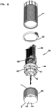
- Figure 1 illustrates a telecommunications enclosure 20 including a housing 22.
- the housing 22 includes a dome 24 that attaches to a base 26.
- the base 26 can include a first end 28 adapted for connection to the dome 24 and a second end 30.
- the first end 28 can connect to the dome 24 by means such as a clamp 32.
- An environmental seal 25 (shown at Figure 3 as an O-ring) can be provided between the base 26 and the dome 24 to provide environmental sealing.
- a telecommunications assembly unit 34 is adapted to be housed within the housing 22.
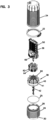
- the telecommunications assembly unit 34 includes a fiber optic manager 36 coupled to a gel sealing unit 38.
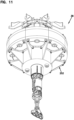
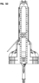
- the gel sealing unit 38 includes a gel sealing block 40 that mounts within an actuator 42.
- the gel sealing block 40 fits within a gel-block mounting sleeve 44 confined within the base 26, and the fiber optic manager 36 is enclosed within the dome 24. It will be appreciated that the telecommunications assembly unit 34 can be loaded into the base 26 through the second end 30 of the base 26. Once the gel sealing block 40 is within the gel-block mounting sleeve 44, the gel sealing block 40 can be axially compressed by the actuator 42 to provide sealing.
- Sealing can include sealing of any cables routed through the cable ports defined by the gel sealing block 40, and can also include peripheral sealing 46 defined between a radially outwardly facing gel surface 41 of the gel sealing block 40 and a radially inwardly facing surface 43 of the gel-block mounting sleeve 44.
- the peripheral sealing can be also called a circumferential sealing can extend circumferentially around the gel sealing block 40.
- the actuator 42 is actuated to pressurize the gel sealing block 40 axially causing the gel of the gel sealing block 40 to flow to fill any voids and to press/expand radially outwardly against the inwardly facing radial surface 43 of the gel-block mounting sleeve 44 to provide an effective peripheral seal.
- relatively strong adhesion can develop between the radially outwardly facing surface 41 of the gel sealing block 40 and the radially inwardly facing surface 43 of the gel-block mounting sleeve 44. This type of adhesion can make it difficult to remove the gel sealing block 40 from the base 26 at a later date.
- the present invention relates to a gel sealing unit 38 which is configured to be capable of applying compressive spring load to the gel sealing block 40 to effect sealing, and also capable of applying tensile load to the gel sealing block 40 to cause the gel sealing block 40 to radially constrict such that adhesion between the outer surface of the gel sealing block 40 and the inner surface of the gel-block mounting sleeve 44 is broken or weakened. In this way, removal of the gel sealing unit 38 from the base 26 is facilitated.
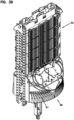
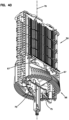
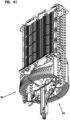
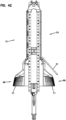
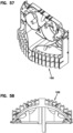
- the fiber manager 36 includes a fiber management tower 50 capable of pivotally supporting a plurality of fiber management trays 61 (one tray is shown at Figures 38-43 , but typically a plurality of stacked and overlaid pivotal trays are provided at opposite sides of the fiber management tower 50).
- sets of fiber management trays can be pivotally mounted in a stacked relationship on opposite first and second major sides 51, 53 of the fiber management tower 50.
- the trays can be snapped into receptacles 63 at the major sides 51, 53 of the tower 50.
- the fiber management trays can be adapted to hold fiber optic components such as fiber optic splices, wavelength division multiplexers, passive optical splitters, and the like.
- fiber routing to the trays can be provided at opposite minor sides 54, 55 of the tower 50.
- the fiber management tower 50 can include a lower support extension 56 (e.g., a projection) that couples to an anchoring bracket 60 configured to be locked or fixed within an interior of the base 26.
- the anchoring bracket 60 can also be coupled to the gel sealing unit 38.
- the anchoring bracket 60 can provide a means for axially fixing/supporting the entire telecommunications assembly unit 34 within the interior of the housing 22.
- the anchoring bracket 60 can interconnect with the base 26 by a twist-to-lock configuration.
- cable anchoring units 62 can be mounted on the gel sealing unit 38 and/or to the anchoring bracket 60.
- the cable anchoring units 62 can mount within/to intermediate adapters 64 that attach to the gel sealing unit 38 and/or the anchoring bracket 60 by means such as a snap-fit connection.
- the adapter 64 can be configured to receive a plurality of cable anchoring units 62, or can be configured to receive single cable anchoring units. It will be appreciated that different styles and types of cable anchoring units 62 can be fitted in the adapter 64 so as to be compatible with different type sizes and types of cables routed through the gel sealing unit 38. In other examples, cable anchoring units 62 may be mounted directly to the anchoring bracket 60 without the use of intermediate adapters 64.
- the anchoring bracket 60 can include snap-fit structures, hooks, tabs, rails, slot openings, or other structures for allowing adapters and/or cable anchoring structures and/or adapters to be readily attached to the anchoring bracket 60.
- the anchoring bracket 60 can have a spoked configuration with a plurality of arms that project radially outwardly from a central hub.
- pressurization structures of the actuator 42 can also have a spoked configuration with arms that project radially outwardly from the central hub.
- fiber management tubes are routed between the cable anchoring structures 62 and the fiber management tower 50. In certain examples, it is preferred for these fibers to be routed within protective tubes (e.g., buffer tubes, furcation tubes, etc.) between the cable anchoring structures 62 and the fiber management tower 50. In certain examples, the protective tubes can be held within tube mounts (e.g., tube holders or like structures). It is preferred for the tube mounts to be configured to efficiently utilize space within the housing 22 for tube routing. In certain examples, the base 26 and the dome 24 are circular or cylindrical in shape. In certain examples, tube mounts 66 having curvatures that generally conform to the shape of the base 26 and/or the dome 24.
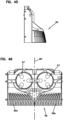
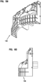
- the tube mounts 66 can be provided at the major sides 51, 53 of the fiber management tower 50 (see Figures 38-50 ). Preferably, the tube mounts 66 can be provided at a base of the fiber management tower 50.
- fiber management spools or bend radius limiters 67 can be provided above the tube mounts 66 for facilitating routing fibers without violating minimum bend radius requirements of the optical fibers.
- the bend radius limiters 67 or spools can be used to readily route fibers in a figure-eight shape or partial figure-eight shape to smoothly transition fibers to either of the minor sides 54, 55 of the fiber management tower 50 regardless of where the fibers are routed through the tube mount 66.
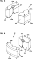
- tube mount 66 can include an overall body defining a plurality of tube holders 69 in the form of open sided grooves/slots sized to frictionally hold tubes therein.
- the tube holders can be arranged in a row or rows.
- a mid-plane MP bisects the major sides 51, 53 of the fiber management tower 50, and the tube holders 69 are depicted as curved slots. Curved slots 69a on one side of the mid-plane MP are configured to curve toward the minor side 54 of the tower 50 as the slots extend upwardly from bottom ends 71 to top ends 73 of the slots.
- curved slots 69b on the opposite side of the mid-plane MP are configured to curve toward the minor side 55 of the tower 50 as the slots extend upwardly from bottom ends 71 to top ends 73 of the slots.
- an overall shape of the body of the tube mount 66 is curved along curves along a curvature 75 that extends about a central axis 79 of the base 26. The curvature 75 extends along a length L of the body, and the holders 69 are spaced along the length L.
- an outer face 77 of the body of the tube mount 66 has a convex curvature that extends generally about the central axis 79 across a width of the major sides 51, 53, and an inner face of the body of the tube mount 66 has a concave curvature that extends about the central axis 79 across the width of the major sides 51, 53.
- the outer face 77 of the body of the tube mount 66 can also have a convex curvature that extends from bottom side to a top side of the body of the tube mount 66.
- the curved arrangement of the tube mount assists in effectively utilizing space within the housing 22 for fiber routing.
- Markings 81 can be provided on the outer face 77 to indicate preferred termination/ending locations for the tubes to leave room for tube expansion.
- Figures 51-60 show an alternative tube mount 166 having an overall body shape that is curved along curves along a curvature 175 that extends about a central axis 79 of the base 26.
- the curvature 175 extends along a length L of the body, and tube holders 169 are spaced along the length L.
- the length L extends across a width of the corresponding major side of the tower 50.
- the tower 50 can also be referred to as a tray mount.
- Tube mount 166 can be positioned at the bottom of each of the major sides 51, 53.
- the tube holders 169 are depicted as closed channels.
- the closed channels can be defined by flexible arms 171 that can be flexed apart to allow tubes to be inserted in the channels.
- the gel sealing block 40 includes a plurality of individual gel sealing modules 90 that cooperate to define the gel block 40. While gel sealing modules are all depicted having the same configuration and each define a single cable port, it will be appreciated that gel sealing modules having the same form factor but different port configurations can be used and can be mixed and matched in a given gel block.
- Example cable sealing modules can include 1, 2, 3, 4, 5, 6 or more cable ports. Additionally, cable sealing modules having different port shapes (e.g., round, obround, race-track shaped, etc.) can be used. Blank sealing modules with no ports can also be used.
- each of the gel sealing modules 90 can have a truncated wedge shape.
- Figures 6 and 7 show one of the gel sealing modules 90 having the truncated wedge shape.
- the depicted gel sealing module 90 includes first and second opposite sides 702, 704 that converge as the first and second opposite sides 702, 704 extend from a major end 706 to a minor end 708 of the main body of the gel sealing module 90.
- the minor end 706 has a concave curvature and the major end 708 has a convex curvature.
- the major ends 706 cooperate to define the radially outwardly facing gel surface 41 that seals against the radially inwardly facing surface 43 of the gel-block mounting sleeve 44.
- the minor ends 708 cooperate to define a radially inwardly facing surface adapted to seal against a component of the gel sealing unit (e.g., an outer circumferential surface of a structure such as the mounting sleeve 231 shown at Figures 19 and 29 .)
- the gel sealing modules 90 can be individually and separately removable from between inner and outer pressurization structures 201, 202 of the actuator 42.
- at least a plurality of the removable gel sealing modules 90 include cable sealing modules each defining at least one cable port 203.
- at least some of the gel sealing modules 90 include at least first and second gel portions 204, 206 (e.g., volumes of gel) that meet at a separable interface 208 at which at least one cable port 203 is defined.
- the first and second gel portions 204, 206 are capable of being separated from one another when the cable sealing module 90 is not mounted between the inner and outer pressurization structures 201, 202 to allow a cable to be laterally inserted into the cable port 203 (i.e., the gel sealing modules can have a wrap-around design).
- the gel sealing module 90 can also include end caps 209 between which an axis 210 the cable port 203 extends.
- the end caps 209 can function to provide gel containment when the gel block is pressurized during sealing.
- the end cap can include flexible fingers 212 at the cable ports 203 to provide gel containment around a cable and to allow the end caps to accommodate cables having a range of different diameters.
- the fingers 212 can flex open to accommodate a cable in the cable port 203.
- the end caps 209 can include first end cap portions 209a attached to opposite ends of the first gel portion 204 and second end cap portions 209b attached to opposite ends of the second gel portion 206.
- the first and second end cap portions 209a, 209b are carried with their respective first and second gel portions 204, 206 when the gel portions 204, 206 are separated from one another.
- the first and second end cap portions 209a, 209b separate from one another when the first and second gel portions 204, 206 are separated from one another.
- "separated" means that at least portions can be moved apart from one. In the case where separate parts of a gel module are connected by a flexible means such as a living hinge, the separate parts can be separated from one another by flexing the living hinge and are the parts are considered separated from one another even though the parts are still connected by the living hinge.
- the end caps 209 include snap-fit structures for coupling in a snap-fit connection interface with the inner and outer pressurization structures 201, 202.
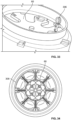
- the snap-fit structures include axially extending pins 214 (e.g., posts) with enlarged heads 216 that are received within snap-fit collars 218 carried with the inner and outer pressurization structures 201, 202.
- the pins 214 can be parallel to the cable port axis 210.
- the collars 218 can be provided on the sealing modules and the pins 214 can be provided on the pressurization structure 201, 202.
- the collars 218 are configured to elastically flex open to receive the enlarged heads 216 and then snap back toward a closed position once the heads 216 have passed therein to provide a snap-fit coupling.
- the collars 218 can include internal pockets or receptacles for receiving the heads 216.
- the snap fit components are snapped together by motion in an axial direction (e.g., along the cable ports and a central axis of the actuator and the enclosure).
- other types of snap-fit interfaces such as flexible latches, tabs, cantilevers, and the like can be used.
- the snap-fit configuration provide a means for the inner and outer pressurization structures 201, 202 to apply tension to the gel block 40 when the gel block is mounted in the actuator 42.
- the inner and outer pressurization structures 201, 202 are forced apart from one another by a trigger arrangement of the actuator 42, tensile load is applied to the gel block 40 through the snap-fit interfaces.
- snap-fit interface are preferred, other types of interfaces capable of transferring tensile load can also be used.
- the end caps and the pressurization structures can have mating rails and channels that slide together (e.g., in a radial direction) or like structures.
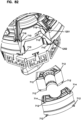
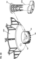
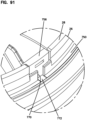
- Figures 81 and 82 show an alternative gel sealing unit 1038 having the same configuration as the gel sealing unit 38 except gel sealing modules are attached to the actuation structure by an interface arrangement including intermating rails and grooves capable of transferring tensile loads from the actuator to the gel sealing modules.
- the depicted gel sealing module 1090 includes end caps with rails 710 that fit within corresponding channels 712 defined by inner and outer pressurization structures 1201, 1202.
- the gel sealing modules 1090 are loaded between the pressurization structures 1201, 1202 by inserting the gel sealing modules 1090 inwardly in a radial direction toward a central axis of the gel sealing unit 1038.
- Each of the gel sealing modules 1090 also includes two flexible latches 714 for preventing the gel sealing modules 1090 from being radially withdrawn from between the pressurization structures 1201, 1202.
- the flexible latches 714 are integrally formed with end caps of the gel sealing modules 1090.
- the flexible latches 714 have a cantilevered configuration.
- the flexible latches 714 are integrated with the end caps of the gel sealing modules 1090 that are positioned adjacent to the inner pressurization structure 1201.
- the inner pressurization structure 1201 can include catches 716 adjacent the outer perimeter of the inner pressurization structure 1201 that are adapted to engage with the flexible latches 714 when the gel sealing modules 1090 are fully inserted into the gel sealing unit 1038.
- the flexible latches can be provided at the end caps corresponding to the outer pressurization structure 1202 and the outer pressurization structure 1202 can include corresponding catches. By flexing the flexible latches 714 toward one another, the flexible latches 714 can disengage from their corresponding catches 716 to allow the gel sealing modules 1090 to be removed from the gel sealing unit.
- the flexible latches 714 include outward projections that can be grasped between a technicians thumb and forefinger to allow the flexible latches 714 to be pressed together.
- the flexible latches 714 are located at the major ends of the gel sealing modules adjacent to the opposite sides of the gel sealing modules. Preferably, the latches of a given one of the gel sealing modules can be manually pressed toward each other to disengage the latches 714 from the catches 716.
- gel sealing modules are selected to populate the gel block based on the types and sizes of cables desired to be routed into the enclosure through the gel block.
- a gel sealing module compatible with the cable is selected and a cable anchoring unit compatible with the cable and the selected gel sealing module is also selected.
- the inside radial portion (e.g., gel portion 204) of the gel sealing module is then snapped into the actuator between the pressurization structures, which are in an open orientation in which the pressurization structures are axially far enough apart to allow for insertion of the inside radial portion.
- the cable is then attached to the selected cable anchor which is then secured to the anchoring bracket 60.
- An optical fiber or fibers of the cable can extend beyond the anchoring location and can be contained in a protective tube (e.g., a buffer tube of the cable, a furcation tube, etc.) that is routed to the tube holder adjacent the fiber manager.
- the tube terminates at the tube holder and the optical fiber(s) continues to the fiber manager where the fibers or fibers can be routed to trays of the fiber manager.
- the bend radius limiters can be used to transition the optical fibers from the tubes that terminate at the tube holder to a routing path that extends up the tower of the fiber manager to a tray.
- the outside radial portion (e.g., portion 206) of the gel sealing module is then snapped between the pressurization structures with the cable captured in a cable port defined between the inside and outside radial portions of the gel sealing module. This process is repeated until the full gel block 40 has been installed in the actuator 42. Thereafter, the telecommunications assembly 34 can be inserted into the base 26 through the outer end 30 of the base 26 and the bracket 60 is locked in the base to anchor the assembly 34 in a position where the gel sealing block 40 is in the base 26. The actuator 42 is then actuated to pressurize the gel block within the base 26 to provide cable sealing and peripheral sealing. To remove the assembly 34, the actuator is used to tension the gel block, the bracket 60 is unlocked from the base, and the assembly 34 is pulled out through the end 30 of the base 26.
- the actuator 42 is then actuated to pressurize the gel block within the base 26 to provide cable sealing and peripheral sealing.
- the gel sealing unit 38 can include the gel sealing block 40 and the actuator 42 capable of applying compressive load to the gel sealing block 40 to provide or enhance sealing.
- the actuator includes the inner and outer pressurizations structures 201, 202 between which the gel sealing block 40 mounts.
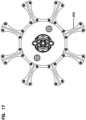
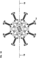
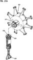
- the pressurization structures 201, 202 can have a spoked configuration with radial arms on which the snap-fit collars 218 are positioned (see Figure 21B ).
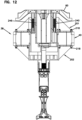
- the actuator 42 includes a trigger arrangement 220 (see Figures 14-30 ) for transferring compressive load to the pressurization structures 201, 202.
- the trigger arrangement 220 includes a threaded first shaft 222 that extends along a first axis 224 along which the outer pressurization structure 202 can axially move to apply the compressive load to the gel sealing block 40.
- the trigger arrangement 220 includes a nut 226 threaded on the shaft 222.
- the nut 226 is rotatable about the first axis 224 relative to the outer pressurization structure 202 and is axially fixed relative to the outer pressurization structure 202.
- axially fixed it is generally meant that the parts that are axially fixed relative to one another are coupled or connected so as to generally move axially together as a unit.
- an outer annular grove 229 surrounding the nut 226 is snapped into a snap-fit sleeve 227 (see Figure 21A ) of the outer pressurization structure 202 to axially lock or fix the nut 226 in place relative to the outer pressurization structure while allowing the nut to turn/rotate relative to the outer pressurization structure 202.
- the nut 226 is integrated or coupled to a handle 228 for turning the nut 226 relative to the outer pressurization structure 202 and the threaded first shaft 222.
- the trigger arrangement 220 also includes a pressurization structure mount 230 for mounting the inner pressurization structure 201.
- the mount 230 can include a mounting sleeve 231 having an outer circumferential surface against which a radially inwardly facing gel surface of the gel block 40 seals when pressurized.
- the inner pressurization structure 201 includes a plurality of separate pressurization sections 232 that are independently slidable relative to the mounting sleeve 231 along the first axis 224.
- the pressurization sections 232 can include webs 234 that slide within slots 236 at an upper end of the mounting sleeve 231.
- the slots 236 have closed lower ends 238 that engage the webs 234 function as positive stops when the trigger arrangement 220 is used to tension the gel block 40.
- the pressurization sections 232 each include two arms carrying collars 218 for snapping together with the upper pins 214 of the gel modules.
- the trigger arrangement 220 including separate springs 240 corresponding to each of the separate pressurization sections 232.
- the spring 240 are captured between first spring stops 242 on the pressurizations sections 232 and second spring stops 244 on the anchor bracket 60 (see Figure 12 ).
- the anchor bracket 60 is fixed to a top end of the mounting sleeve 231 by fasteners or other means.
- the spring 240 fit within vertical bores 246 defined by the pressurization structures 232.
- the threaded first shaft 222 has an upper end 250 that is axially and rotatably fixed relative to the mounting sleeve 231.
- the sleeve 231 defines a T-shaped slot 252 that receives a T-shaped flange 254 at the upper end 250 of the shaft 222.
- the flange 254 can snap within the slot 252.
- the gel sealing block 40 is coupled to the inner and outer pressurization structures 201, 202 by a coupling that allows the inner and outer pressurization structures to apply a tension load to the gel sealing block (e.g., the snap-fit interface described above or other type of interface).
- the gel sealing block 40 includes the plurality of individual gel sealing modules 90 that cooperate to define the gel block 40 with each gel sealing module 90 corresponding to one of the separate pressurization sections 232 of the inner pressurization structure 201.
- the nut 226 When the nut 226 is threaded (e.g., via the handle 228) in a first rotational direction about threaded first shaft 222 the nut 226 and outer pressurization structure 202 move axially in a first direction along the threaded first shaft 222 toward the inner pressurization structure 201 causing the gel block 40 to be forced against the inner pressurization structure 201 and the inner pressurization structure 201 to be forced against the springs 240 causing the springs 240 to be compressed and spring compression load to be axially applied to the gel sealing block 40.
- the gel block is spring pressurized and cause to flow/deform to fill any voids within the base and to effectively seal about any cables in the cable ports and to form an outer peripheral seal with the base 26 and an inner seal around the mounting sleeve 231.
- the nut 40 is threaded in a second rotational direction about the first shaft 222 the nut 226 and the outer pressurization structure 202 move axially in a second direction along the threaded first shaft 222 away from the inner pressurization structure 201 causing the gel block 40 and the inner pressurization structure 201 to be pulled away from springs 240 such that the spring de-compress.
- the outer surface of the gel block 40 may still be strongly bonded to the inner surface of the base 26.
- the nut 226 can continue to be rotated on the shaft 222 in the second direction causing the inner pressurization structure to be pulled into engagement with a positive stop (e.g., the webs 234 of the inner pressurization structures contact the bottom ends of the slots 236) of the mounting sleeve 231 causing the inner and outer pressurization structure 201, 202 to be positively pulled apart as the outer pressurization structure 202 and the nut 226 continue to move in the second direction such that tension is applied to the gel sealing block through the snap-fit interface. Tensioning of the gel block can cause it to constrict thereby loosening adhesion with the base.
- the sealing unit 28 can then be removed from the base more easily.
- the bracket 60 is carried with the sealing unit 38 and the remainder of the telecommunications assembly unit 34.
- the bracket moves through the base 26 and is preferably oriented in a first rotational position relative to the base.
- the base includes a bracket connection interface 300 near the first end of the base.
- the bracket 60 can be rotated relative to a central axis of the base to move the bracket 60 from the first rotational position to a second rotational position in which the bracket 60 engages the connection interface 300 and is axially fixed relative to the base 26.
- portions of the bracket 60 can be captured between upper and lower flanges or other retainers coupled to the base.
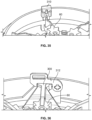
- FIG. 31 shows the bracket 60 in the second rotational position with a fastener such as a screw 302 being used to prevent the bracket from rotating from the second rotational position back to the first rotational position.
- Figure 32 shows the bracket 60 retained in the second rotational position by a snap fit 304.
- Figure 33 shows the bracket 60 retained in the second rotational position by an axial slide latch 306.
- Figure 34 shows a slide latch 308 that axially retains the bracket 60 regardless of its rotational position (this example does not require twist to lock since the latch secures the bracket against axial movement relative to the base).
- Figure 35 shows the bracket 60 retained in the second rotational position by another axial slide latch 310.
- Figure 36 shows the bracket 60 retained in the second rotational position by a pivotal latch 312.
- Figure 37 shows the bracket 60 retained in the second rotational position by another pivotal latch 314.
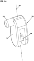
- Figure 84 shows the bracket 60 retained in the second rotational position by a resilient clip 730 .
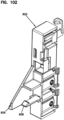
- Figures 85-98 show an example assembly error prevention arrangement 740 (i.e., a poka yoke arrangement) for preventing the dome 24 from being coupled to the first end 28 of the base 26 before the anchoring bracket 60 suitably secured within the base 26.
- the first end 28 of the base 26 defines a circumferential groove 750 for receiving a circumferential edge of the open end of the dome 24.
- the base 26 includes a connection interface 300 in the form of a plurality of circumferential bracket anchoring slots 752 for axially anchoring the anchoring bracket 60 relative to the base 26 when the anchoring bracket 60 is in the second rotational position.
- the slots 752 are circumferentially spaced about the interior of the base 26.
- the anchoring bracket 60 includes a plurality of radial arms, and that end portions of the radial arms slide within the bracket anchoring slots 752 when the bracket 60 is rotated to the second rotational position.
- the bracket anchoring slots 752 include open ends and closed ends. When the anchoring bracket 60 is rotated from the first rotational position to the second rotational position, the end portions of the radial arms of the anchoring bracket 60 enter the bracket anchoring slots 752 through the open ends of the slots.
- the closed ends of the bracket anchoring slots 752 can function as positive stops for stopping rotation of the anchoring bracket when the anchoring bracket 60 reaches the second rotational position.
- the bracket 60 is in the second rotational position, the end portions of the radial arms of the bracket are captured between upper and lower surfaces which define the bracket anchoring slots 752 so as to prevent axial movement of the bracket 60 relative to the base 26.
- the assembly error prevention arrangement 740 includes a slide member 756 that is slidable relative to the base along a slide orientation 757 that extends between the first and second ends 28, 30 of the base 26.
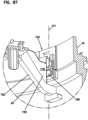
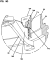
- the slide member 756 is slidable along the slide orientation 757 (see Figures 86 and 87 ) between a dome-blocking position (see Figures 86 , 88 , 89 , and 90 ) and an anchor bracket retention position (see Figures 87 and 91 ).
- the slide member 756 prevents the dome 24 from being installed at the first end 28 of the base 26 when the slide member 756 is in the dome blocking position.
- the slide member 756 allows the anchor bracket to be rotated from the first rotational position to the second rotational position when the slide member 756 is in the dome blocking position.
- the slide member 756 allows the dome 24 to be installed at the fist end 28 of the base 26 when the slide member 756 is in the anchor bracket retention position.
- the slide member 756 prevents the anchor bracket from being rotated from the second rotational position to the first rotational position when the slide member 756 is in the anchor bracket retention position.
- the base 26 includes a sidewall 758 including a mounting structure 760 adjacent the first end 28 of the base 26 for slidably receiving the slide member 756.
- the mounting structure 760 includes a main receptacle 762 for receiving a main body 764 of the slide member 756.
- the mounting structure 760 can also include an inner slot 766 for receiving a bracket blocking projection 768 of the slide member 756 and an outer slot 770 for receiving a dome blocking projection 772 of the slide member 756.
- the inner and outer slots 766, 770 have lengths that extend along the slide orientation 757.
- the bracket blocking projection 768 slides along the inner slot 766 and the dome blocking projection 772 slides along the outer slot 770 as the slide member 756 moves between the dome blocking position (see Figures 86 and 88 ) and the bracket retention position (see Figures 87 and 91 ).
- the slide member 756 includes a flexible latch 774 that engages a catch 776 of the mounting structure 760 provided inside the base 26.
- the flexible latch 774 engages the catch 776 via a snap-fit connection to retain the slide member 756 within the receptacle 762 while concurrently allowing the slide member 756 to slide along the slide orientation 757 between the dome blocking position and the bracket retention position.
- the first end 28 of the base 26 defines the circumferential groove 75 for receiving an end of the dome 24.
- the dome blocking projection 772 is positioned within the circumferential groove 750 so as to provide an obstruction that prevents the bottom end of the dome from being inserted into the groove 750.
- the dome blocking projection 768 is recessed relative to the circumferential groove 750 such that the circumferential groove 750 is not obstructed and the end of the dome 24 can readily be inserted therein.
- bracket blocking projection 768 of the slide member 756 opposes a stop surface 778 of a flange 780 of one of the radial arms 782 to prevent the anchor bracket 60 from being rotated relative to the base 26 from the second rotational position to the first rotational position.
- bracket blocking projection 768 is offset from the flange 780 (e.g., positioned above as shown at Figure 86 ) so as to not interfere with the ability to rotate the bracket 60 between the first and second rotational positions.
- the bracket blocking projection 768 can have a lower end having angled surfaces 784 that facilitate moving the bracket blocking portion 768 past the flange 780 when the slide member 756 is moved from the dome blocking position to the bracket blocking position.
- the assembly prevention arrangement 740 includes a linkage 786 which includes both the slide member 756 and a pivot link 788 pivotally connected to the slide member 756 at a pivot axis 790.
- the pivot link 788 includes a main link body 792 that pivots about the pivot axis 790 between a first pivot position (see Figures 86 and 92 ) and a second pivot position (see Figures 87 and 93 ) as the slide member is moved between the dome blocking position (see Figure 86 ) and the bracket retention position (see Figure 87 ).
- the pivot link 788 is in the first pivot position when the slide member 756 is in the dome blocking position and the pivot link 788 is in the second pivot position when the slide member 756 is in the bracket retention position.
- the main link body 792 has a lengthwise axis 794 that passes through the pivot axis 790.
- the lengthwise axis 794 is parallel to the slide orientation 757 of the slide member 756 such that the pivot link 788 prevents the slide member 756 from being manually moved along the slide orientation 757 by pressing on the slide member 756.
- the pivot link 788 also includes an inwardly projecting pin 796.
- the pin 796 is positioned such that when the anchoring bracket 60 is rotated from the first rotational position to the second rotational position, the anchoring bracket contacts the inwardly projecting pin 796 causing the pivot link 788 to pivot from the first pivot position toward the second pivot position thereby causing the slide member 756 to move from the dome blocking position toward the anchor bracket retention position.
- the flange 780 of the arm 782 of the anchoring bracket 60 engages the inwardly projecting pin 796 to initiate movement of the pivot link 788 from the first pivot position toward the second pivot position.
- the bracket blocking projection 768 of the slide member 756 moves into a position that opposes the stop surface 778 of the flange 780 after the flange 780 has moved past the bracket blocking projection 768 as the anchoring bracket 60 is rotated from the first rotational position toward the second rotational position.
- Figure 86 shows the bracket blocking projection 768 offset from the stop surface 778 so as to not obstruct rotational movement of the bracket 60
- Figure 87 shows the bracket blocking projection 768 in opposition with respect to the stop surface 778.
- the pivot link 788 includes a pivot element 798 through which the pivot axis 790 extends.
- the pivot element 798 has a polygonal cross-sectional shape. In one example, the polygonal cross-sectional shape is square, but other shapes can be used as well.
- the slide member 756 has a pivot receiver 800 that receives the pivot element 798.
- the pivot receiver 800 is best shown at Figures 97 and 98 .
- the pivot receiver 800 has a polygonal cross-sectional shape that matches the polygonal cross-sectional shape of the pivot element 798.
- the pivot element 798 pivots within the pivot receiver 800 when the pivot link 788 is pivoted about the pivot axis 790.
- the pivot receiver 800 has a resilient construction that elastically deforms or flexes to accommodate pivotal movement between the pivot element 798 and the pivot receiver 800.
- the matching polygonal cross-sectional shapes of the pivot element 798 and the pivot receiver 800 combined with the resilient, elastic construction of the pivot receiver 800 require a predetermined force to be applied to the pivot link 788 to cause the pivot receiver 800 to elastically flex a sufficient amount to allow the pivot link 788 to be moved from the first pivot position to the second pivot position and vice versa.
- the pivot receiver 800 retains the pivot link in the first pivot position and the second pivot position until the predetermined force is applied to the linkage so as to overcome the elastic retention force provided by the pivot receiver.
- the pivot link 788 pivots about 90 degrees between the first pivot position and the second pivot position.
- the pivot element 798 and the pivot receiver 800 provide an over-the-center biasing arrangement that elastically biases the pivot link 788 toward the first pivot position when the pivot link 88 is rotationally closer to the first pivot position than the second pivot position and that biases the pivot link 788 toward the second pivot position when the pivot link is rotationally closer to the second pivot position than the first pivot position.
- the center position coincides with the pivot link having pivoted about 45 degrees between the first pivot position and the second pivot position.
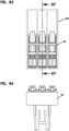
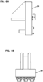
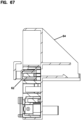
- Figures 61-67 show one of the cable anchor unit adapters 64 for receiving a plurality of cable anchor units 62.
- the adapter 64 includes a rear snap-fit interface 400 including a flexible latch 402 for engaging a mating interface on the bracket 60.
- the adapter 64 includes receptacles for receiving cable anchors 62.
- the adapter also include rear reinforcing ribs 404 that fit within slots 406 defined by the pressurization sections 232 of the inner pressurization structure 201.
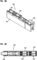
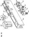
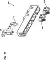
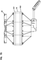
- Figure 68-71 show an example cable anchoring unit 420 including a rectangular main body 422, a first cradle 424 for clamping a cable jacket with a metal band, a second cradle 426 for clamping a cable shield with a metal band, a strength member or conductor anchor 428 for wrapping aramid yarn of a cable or for securing a rigid member such as a metal member or a glass reinforced polymer rod.
- An electrical contact 430 is provided at the anchor 428 for grounding purposes. The contact is connected to a grounding screw 432.
- a cable shield secured at the second cradle 426 can also be connected to the grounding screw, which is between the cradle 426 and the anchor 428.
- Strap tighteners 434 can be provided within the cradles 424, 426 for receiving the ends of straps inserted though slits 436 in the cradles 424, 426.
- Fasteners 438 secure the ends of the straps in slots 440 in the tighteners 434.
- Fasteners 442 move the tighteners downwardly away from the cradles to tighten the straps.
- the anchoring unit 420 can be secured to a bracket or other structure via an intermediate adapter or other structure that may include snap-fit features.
- Figures 72 and 73 show an alternative cable anchoring unit which is the same as the cable anchoring unit 420, except a rear side of the main body has been equipped with an integrated snap-fit structure for attaching the cable anchoring unit directly to an anchor bracket or other structure without the need for an adapter.
- the snap-fit structure can include a snap-fit latch, tab, arm or like structure.
- the rear interface can also include stabilization ribs that can engage an anchoring bracket or a pressurization structure (e.g., the ribs can fit within slots in the inner pressurization structure such as slots 406 defined by the pressurization sections 232 of the inner pressurization structure 201).
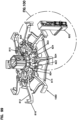
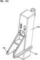
- Figures 99 and 100 show a configuration where cable anchoring units or cable anchoring unit adapters can be mounted directly to the anchoring bracket at a position completely above the gel sealing unit 38.
- the cable anchoring unit adapters and/or the anchoring units do not engage any portion of the gel sealing unit 38 and are instead secured to and stabilized by the bracket alone.
- the cable anchoring units and/or the cable anchoring unit adapters are secured to a hub of the bracket by an interface that includes: a) a groove and rail configuration for stabilizing the cable anchoring device relative to the bracket and for allowing the cable anchoring device to be loaded into the bracket by radially inserting the cable anchoring device into the bracket; and b) a snap-fit connection for releasably retaining the cable anchoring device in an inserted position relative to the bracket.
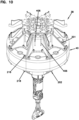
- a bracket 1060 is shown having a hub 810 and a plurality of radial arms 812 that project radially outwardly from the hub 810.
- the bracket 1060 also includes a reinforcing ring 814 that couples to the arms 812 at an intermediate location between the hub 810 and outer ends 816 of the radial arms 812.
- Cable anchoring devices 820 of the type previously described herein are mounted at an upper side of the hub.
- the mounting locations are located circumferentially between the arms 812 and are provided at the hub 810.
- Each of the mounting locations can include a snap-fit catch 822 and stabilizing grooves 824.
- the cable anchoring device 820 can include rails 826 that fit within the grooves 824 for stabilization, and a snap-fit latch 828 between the rails 826 that fits within the snap-fit catch 822.
- Figures 74-79 show another gel sealing unit 538 that can be used with an enclosure such as the enclosure of Figure 1 .
- the gel sealing unit 538 includes the gel sealing block 40 an actuator 542 capable of applying compressive load to the gel sealing block during sealing.
- the actuator 542 includes inner and outer pressurizations structures 501, 502 between which the gel sealing block 40 mounts.
- the actuator 542 includes a trigger arrangement 520 for transferring compressive load to the pressurization structures.
- the trigger arrangement 520 includes a threaded first shaft 522 that extends along a first axis 524 along which the outer pressurization structure 502 can axially move to apply the compressive load to the gel sealing block 40.
- the threaded first shaft 522 including a head 523 that mounts within a pocket 525 defined by the inner pressurization structure 501.
- the head 523 is axially slidable within the pocket 525 along the first axis 524 relative to the inner pressurization structure 501, but is prevented from rotating relative to the inner pressurization structure 501 about the first axis 514 (e.g., by one or more opposing flats or other ant-rotation features).
- the trigger arrangement 520 also including a spring 540 mounted on the threaded first shaft 522 and captured between the head 523 of the threaded first shaft 522 and a spring stop 527 that is axially fixed relative to the inner pressurization structure 501.
- the threaded first shaft 522 extends through the spring stop 527 and is rotatable relative to the spring stop 527 without threadingly engaging the spring stop 527.
- the trigger arrangement 520 also includes a nut 541 threaded on the threaded first shaft 522.
- the nut 541 is rotatable relative to the outer pressurization structure 502 while also being axially fixed relative to the outer pressurization structure 502 such that the outer pressurization structure 502 is carried with the nut 541 axially along the first axis 524 when the nut 541 is threaded on the threaded first shaft 522.
- the trigger arrangement 520 further including a first bevel gear 543 integrated with or coupled to the nut 541.
- the trigger arrangement 520 also including a handle 545 mounted on a second shaft 547 that extends along a second axis 549 angled relative to the first axis 524.
- the second shaft 547 is coupled to a second bevel gear 551 that intermeshes with the first bevel gear 543 such that when the handle 545 is turned about the second axis 549 the second bevel gear 551 turns the nut 541 about the threaded first shaft 522 causing axial movement of the nut 541 and the outer pressurization structure 502 relative to the first threaded shaft 522.
- the shaft 522 When the nut 541 is threaded in a first rotational direction about the shaft 522, the shaft 522 is moved axially in a first direction along the first axis 524 relative to the nut 541 and the outer pressurization structure 502 causing the head 523 of the shaft 522 to slide axially within the pocket 525 of the inner pressurization structure 502 in the first direction along the first axis 524 toward the spring stop 527 causing the spring 540 to be compressed between the head 523 and the spring stop 527 which causes the threaded first shaft 522 to be placed in tension such that spring compression load is axially applied to the gel sealing block 40 between the inner and outer pressurization structures 501, 502.
- the angled configuration of the handle allows the handle to be readily accessed even if the gel block is densely packed with cables.
- the gel sealing block 40 is preferably coupled to the inner and outer pressurization structures 501, 502 by a coupling of the type described above that allows the inner and outer pressurization structures 50, 502 to apply a tension load to the gel sealing block 40.
- the shaft 522 is moved axially in a second direction along the first axis 524 relative to the nut 541 and the outer pressurizations structure 502 causing the head 523 of the shaft 522 to slide axially within the pocket 525 of the inner pressurization structure 501 in the second direction along the first axis 524 away from the spring stop 527 as the spring is de-compressed.
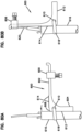
- Figures 80A and 80B show another cable anchoring unit 600 that can be attached to a bracket such as the bracket 60 or used in other applications.
- the anchoring unit 600 includes a member having first leg 602 angled relative to a second leg 604.
- a strength member fastening element 606 is mounted on the first leg 602.
- a cam surface 608 is provided at a transition between the first and second legs 602, 604.
- a cable tie opening 610 is defined though the member.
- the opening 610 is closer to a surface 612 of the second leg 604 than a surface 614 of the first leg 602. In use, the surface 612 of the second leg 604 is placed against a cable 616 and a cable tie 618 is wrapped in a loop about the cable 616 and through the opening 610.
- the member is pivoted to a position where the surface 614 is placed against the cable.
- the opening 610 is further from the cable than when the anchor was in the first pivotal position.
- pivoting the member from the first position to the second position causes tightening of the tie 618.
- a strength member 620 of the cable 616 can be secured to the first leg 602 by the fastening element 606.
Landscapes
- Physics & Mathematics (AREA)
- General Physics & Mathematics (AREA)
- Optics & Photonics (AREA)
- Light Guides In General And Applications Therefor (AREA)
- Transmitters (AREA)
- Casings For Electric Apparatus (AREA)
- Insertion, Bundling And Securing Of Wires For Electric Apparatuses (AREA)
- Executing Machine-Instructions (AREA)
- Cable Accessories (AREA)
Description
- This application claims the benefit of
U.S. Patent Application Serial No. 62/524,240, filed on June 23, 2017 U.S. Patent Application Serial No. 62/622,644, filed on January 26, 2018 - The present disclosure relates generally to sealed telecommunications enclosures.
- Telecommunications systems typically employ a network of telecommunications cables capable of transmitting large volumes of data and voice signals over relatively long distances. The telecommunications cables can include fiber optic cables, electrical cables, or combinations of electrical and fiber optic cables. A typical telecommunications network also includes a plurality of telecommunications enclosures integrated throughout the network of telecommunications cables. The telecommunications enclosures are adapted to house and protect telecommunications components such as splices, termination panels, power splitters and wavelength division multiplexers.
- It is often preferred for the telecommunications enclosures to be re-enterable. The term "re-enterable" means that the telecommunications enclosures can be reopened to allow access to the telecommunications components housed therein without requiring the removal and destruction of the telecommunications enclosures. For example, certain telecommunications enclosures can include separate access panels that can be opened to access the interiors of the enclosures, and then closed to re-seal the enclosures. Other telecommunications enclosures take the form of elongated sleeves formed by wrap-around covers or half-shells having longitudinal edges that are joined by clamps or other retainers. Still other telecommunications enclosures include two half-pieces that are joined together through clamps, wedges or other structures.
- Telecommunications enclosures are typically sealed to inhibit the intrusion of moisture or other contaminants. Pressurized gel-type seals have been used to effectively seal the locations where telecommunications cables enter and exit telecommunications enclosures. Example pressurized gel-type seals are disclosed by document
EP 0442941 B1 and documentEP 0587616 B 1 . Both of these documents disclose gel-type cable seals that are pressurized through the use of threaded actuators. DocumentUS 6,046,406 discloses a cable seal that is pressurized through the use of an actuator including a cam lever.PCT Patent Publication Nos. WO 2014/095462 andWO 2014/005916 disclose enclosures having gel blocks with individually removable gel sealing modules. While pressurized cable seals have generally proven to be effective, improvements in this area are still needed. Patent publications -WO 2014/005918 A2 andWO 2014/005919 A2 - disclose relevant background information that may be useful for understanding the present invention. - The present invention is defined by appended independent claim 1. Optional features are defined by the appended dependent claims. One aspect of the present disclosure relates to an enclosure having a sealing unit with a gel block capable of being placed under tension to facilitate removal of the gel block from the enclosure.
- Another aspect of the present disclosure, not covered by claims, relates to a method for removing a gel block from a gel-block mounting sleeve of a housing. The gel block is moved along an axis relative to the gel-block mounting sleeve during removal of the gel block from the gel-block mounting sleeve. The method includes placing the gel block in axial tension along the axis while the gel block is in the gel-block mounting sleeve to at least partially break or reduce adhesion between a radially outwardly facing surface of the gel and a radially inwardly facing surface of the gel-block mounting sleeve. The method also includes removing the gel block from the gel-block mounting sleeve by moving the gel block along the axis relative to the gel-block mounting sleeve after the gel has been placed in tension. In the above example, the gel can be maintained in tension as the gel block is removed from the gel-block mounting sleeve. In any of the above examples, the gel can be placed in tension by an actuator that is also used to apply axial compressive load to the gel to enhance sealing of the gel within the gel-block mounting sleeve. In any of the above examples, the actuator can include at least one spring or a plurality of springs for applying axial compressive load to the gel in the form of compressive spring pressure. In any of the above examples, the gel can define at least one axially extending cable sealing port. In any of the above examples, the gel can define a plurality of axially extending cable ports. In any of the above examples, the gel block can include a plurality of individual gel sealing modules that cooperate to define the gel block. In any of the above examples, the actuator can include inner and outer pressurization structures between which the gel block is pressurized during sealing. In any of the above examples, the gel sealing modules can be attached to inner and outer pressurization structures of an actuator by snap-fit connections capable of transferring tensile load from the pressurization structures to the gel sealing modules. In certain examples, the snap-fit connections can be made by snap-fit interface components which snap together in an axial orientation. In certain examples, the snap-fit interface components can include posts and snap-fit collars. In certain examples, the gel sealing modules are individually and separately removable from between inner and outer pressurization structures and at least a plurality of their removable gel sealing modules are cable sealing modules each including: at least first and second gel portions that meet at a separable interface at which at least one cable port is defined, the first and second gel portions being capable of being separated from one another when the cable sealing module is not between the inner and outer pressurization structures to allow a cable to be inserted laterally into the cable port; and end caps between which cable ports extend, end caps each including first end cap portions attached to opposite ends of the first gel portion and second end cap portions attached to opposite ends of the second gel portion, the first and second end cap portions separating from one another when the first and second gel portions are separated from one another. In certain examples, living hinges or other flexible connections can be used to interconnect the separate portions of the cable sealing modules.
- Another aspect of the present disclosure, not covered by claims, relates to a cable sealing module for mounting between pressurization structures of an actuator of a sealing unit. The cable sealing module includes at least first and second gel portions that meet at a separable interface at which at least one cable port is defined. First and second gel portions are capable of being separated from one another when the cable sealing module is not between the pressurization structures to allow a cable to be laterally inserted into the cable port. The cable sealing module also includes end caps between which an axis of the cable port extends. The end caps each include first end cap portions attached to opposite ends of the first gel portion and second end cap portions attached to opposite ends of the second gel portion. The first and second end cap portions separate from one another when the first and second gel portions are separated from one another. The cable sealing module also includes snap-fit structures integrated with the end caps for coupling in a snap-fit connection with the pressurization structures of the actuator. In the above example, the snap-fit structures can include posts or collars. In any of the above examples, the snap-fit structures can include posts having enlarged heads, posts projection outwardly from the end caps in an orientation parallel to the axis of the cable port. In any of the above examples, the separable portions of the cable sealing module can be coupled together by a living hinge their flexible means that allows the portions to be separated from one another at the separable interface while preventing the separable portions from being completely detached from one another. In still other examples, the separable portions of the cable sealing modules can be completely detachable from one another.
- The present invention relates to an enclosure including a housing including a gel-block mounting sleeve. The enclosure also includes a gel sealing unit including: a gel sealing block that mounts within the gel-block mounting sleeve; and an actuator capable of applying compressive load to the gel sealing block during sealing, and capable of applying tensile load to the gel sealing block to facilitate removal of the gel sealing block from the gel-block mounting sleeve. The actuator includes at least one spring for applying the compressive load to the gel sealing block in the form of compressive spring pressure. The actuator includes pressurization structures between which the gel seal block mounts, wherein the gel sealing block is pressurized between the pressurization structures during sealing, when the gel sealing block is coupled to the pressurization structures by a coupled interface that allows the pressurization structures to apply tension to the gel sealing block prior to removal of the gel sealing block from the gel-block mounting sleeve, and wherein during tensioning positioning of the pressurization structure is absolutely controlled by a trigger arrangement of the actuator without influence from the at least one spring. In any of the above examples, the trigger arrangement can apply compressive load for forcing the pressurization structures together through at least one spring and can positively engage the pressurization structures during tensioning such that axial movement of a threaded component of the trigger arrangement is converted into an equal axial increase in a spacing between the pressurization structures. In any of the above examples, the trigger arrangement can engage a positive stop corresponding to at least one of the pressurization structures to provide positive movement of the pressurization structures during tensioning after the one or more springs have been de-compressed. In any of the above examples, the gel block can include a plurality of individual gel sealing modules that cooperate to define the gel block. In any of the above examples, the gel sealing modules can be attached to the inner and outer pressurization structures by snap-fit connections capable of transferring tensile load from the pressurization structures to the gel sealing modules. In any of the above examples, the snap-fit connections are made by snap-fit interface components which snap together in an axial orientation. In any of the above examples, the snap-fit interface components can include posts and snap-fit collars. In any of the above examples, the gel sealing modules can be individually and separately removable from between the pressurization structures and at least the plurality of the removable gel sealing modules are cable sealing modules each including: at least first and second gel portions that meet at a separable interface which at least one cable port is defined, the first and second gel portions being capable of being separated from one another when the cable sealing module is not between the pressurization structures to allow a cable to be laterally inserted into the cable port; and end caps between which the cable port extends, the end caps each including first end cap portions attached to opposite ends of the first gel portion and second end cap portions attached to opposite ends of the second gel portion, the first and second end cap portions separating from one another when the first and second gel portions are separated from one another. In any of the above examples, the end caps can include snap-fit structures for coupling in a snap-fit connection with the pressurization structures. In any of the above examples, the housing can include a dome coupled to a base, wherein the gel-block mounting sleeve is defined within the base. In any of the above examples, the base can include a first end that couples to the dome and an opposite second end, and the gel sealing block can be inserted into the gel-block mounting sleeve through the second end of the base. In any of the above examples, the pressurization structures can include inner and outer pressurization structures, wherein the inner pressurization structures coupled to an anchoring bracket that is carried with the inner pressurization structure when the gel sealing block is inserted into and remove from the base, wherein the anchoring bracket can be axially inserted into the base with the gel sealing block when in a first rotational position relative to the base, and wherein once the gel sealing block and the anchoring bracket have been inserted into the base, the gel sealing block and the anchoring bracket can be rotated relative to the base to a second rotational position where the anchoring bracket is axially affixed within the base. In certain examples, the anchoring bracket is prevented from rotating from the second rotational position back to the first rotational position by a fastener, a snap-fit structure, a clip, a latch, a slide latch, or other structure. A further aspect of the present disclosure relates to an enclosure having a housing including a dome coupled to a base. The base includes a first end that couples to the dome and an opposite second end. The base defines a gel-block mounting sleeve. The enclosure also includes a gel sealing unit including a gel sealing block that mounts within the gel-block mounting sleeve by inserting the gel block through the second end of the base. The enclosure further includes an actuator capable of applying compressive load to the gel sealing block during sealing. The actuator includes inner and outer pressurization structures between which the gel sealing block mounts. The inner pressurization structure is coupled to an anchoring bracket that is carried with the inner pressurization structure when the gel sealing block is inserted into and removed from the base. The anchoring bracket can be axially inserted into the base with the gel sealing block when in a first rotational position relative to the base. Once the gel sealing block and the anchoring block have been inserted into the base, the gel sealing block and the anchoring bracket can be rotated relative to the base to a second rotational position where the anchoring bracket is axially fixed within the base. It will be appreciated that the term "axially fixed" means that movement in the axial direction is generally limited or prevented, but a small amount of substantially non-functional movement may occur. In certain examples, the anchoring bracket is prevented from rotating from the second rotational position back to the first rotational position by a fastener, or a snap-fit structure, or a clip, or a pivoting latch, or a slide latch, or other type of latch, or other structure. In certain examples, fiber optic organizers coupled to the anchoring bracket is carried with the gel sealing unit during insertion into the base, the fiber optic organizer preferably including a plurality of pivotal fiber management trays such as splice trays.
- A further aspect of the present disclosure relates to a gel sealing unit including a gel sealing block and an actuator capable of applying compressive load to the gel sealing block during sealing. The actuator includes pressurization structures between which the gel sealing block mounts. The actuator includes a trigger arrangement for transferring compressive load to the pressurization structures. At least one of the pressurization structures is axially moved along a first axis relative to the other of the pressurization structures when the trigger arrangement is actuated. The trigger arrangement includes a handle that is rotated about a second axis angled relative to the first axis to cause relative movement between the pressurization structures along the first axis. In certain examples, the first and second axes are perpendicular. In any of the above examples, trigger arrangement can include an angled gear arrangement for transferring torque from the handle to a rotatable component of the trigger arrangement that rotates about the first axis. In any of the above examples, the angled gear arrangement can include angled bevel gears. In any of the above examples, the angled bevel gears that include right angle bevel gears. In any of the above examples, the rotatable component can include a nut threaded on a threaded first shaft of the trigger arrangement wherein the threaded first shaft is aligned along the first axis and is configured to be placed in tension when compressive load is applied to the pressurization structures by the trigger arrangement, wherein a first angled bevel gear in integrated with or coupled to the nut, wherein the handle is mounted on a second shaft aligned with the second axis and is rotated about the second axis by turning the handle, and wherein the second shaft is coupled to a second angled bevel gear that intermeshes with the first angled bevel gear.
- A variety of additional inventive aspects will be set forth in the description that follows. The inventive aspects can relate to individual features and to combinations of features. It is to be understood that both the forgoing general description and the following detailed description are exemplary and explanatory only and are not restrictive of the broad inventions and inventive concepts upon which the examples disclosed herein are based.
-
-
Figure 1 illustrates a telecommunications enclosure in accordance with the principles of the present disclosure; -
Figure 2 is an exploded view of the telecommunications enclosure ofFigure 1 ; -
Figure 3 is a further exploded view of the telecommunications enclosure ofFigure 1 ; -
Figure 4 is a cross-sectional view of the telecommunications enclosure ofFigure 1 ; -
Figure 5 is a perspective view of an example gel sealing block used to seal the telecommunications enclosure ofFigure 1 ; -
Figure 6 is a perspective view of a cable sealing module of the gel sealing block ofFigure 5 ; -
Figure 7 is another perspective view of the cable sealing module ofFigure 6 ; -
Figure 8 is an exploded view of the cable sealing module ofFigure 6 ; -
Figure 9 is another exploded view of the cable sealing module ofFigure 6 ; -
Figure 10 is a perspective view of an example gel sealing unit that can be used with the telecommunications enclosure ofFigure 1 ; -
Figure 11 is another perspective view of the gel sealing unit ofFigure 10 ; -
Figure 12 is a cross-sectional view of the cable sealing unit ofFigure 10 ; -
Figure 13 is a perspective view of an actuator of the cable sealing unit ofFigure 10 ; -
Figure 14 is another perspective view of the actuator ofFigure 13 ; -
Figure 15 is a side view of the actuator ofFigure 13 ; -
Figure 16 is another side view of the actuator ofFigure 13 ; -
Figure 17 is a bottom view of the actuator ofFigure 13 ; -
Figure 18 is a top view of the actuator ofFigure 13 ; -
Figure 19 is a cross-sectional view of the actuator ofFigure 13 ; -
Figure 20 is an exploded view of the gel sealing unit ofFigure 10 ; -
Figure 21A illustrates how a handle portion of the gel sealing unit ofFigure 10 is coupled to an outer pressurization structure of the gel sealing unit ofFigure 10 ; -
Figure 21B illustrates how the cable sealing modules of the gel sealing block connect to the outer pressurization structure of the gel sealing module through snap-fit interfaces; -
Figure 22 is a side view of an individual section of an inner pressurization structure of the gel sealing unit ofFigure 10 ; -
Figure 23 shows pressurization structure section ofFigure 22 from an outer radial perspective; -
Figure 24 is another side view of the pressurization structure section ofFigure 22 ; -
Figure 25 shows the pressurization structures section ofFigure 22 from an inner radial perspective; -
Figure 26 is a top view of the pressurization structure section ofFigure 22 ; -
Figure 27 is a bottom view of the pressurization structure section ofFigure 22 ; -
Figure 28 is a cross-sectional view of the pressurization structure section ofFigure 22 ; -
Figure 29 illustrates how one of the pressurization structure sections mounts to a pressurization structure mount of a trigger of the gel sealing module ofFigure 10 ; -
Figure 30 is a more detailed view showing how the pressurization structure section mounts to the pressurization structure mount; -
Figure 31 shows a fastener being used to lock an anchoring bracket suitable for use with the sealing unit ofFigure 10 at a locked rotational position relative to the base; -
Figure 32 shows a snap-fit configuration for locking the anchoring bracket in a rotational position relative to the base; -
Figure 33 shows a slide clip that is used to lock the anchoring bracket in a rotational position relative to the base; -
Figure 34 depicts a slide element for locking the anchoring bracket in the base regardless of rotational orientation; -
Figure 35 illustrates another slide clip for locking an anchoring bracket within the base; -
Figure 36 illustrates a pivot latch for locking an anchoring bracket in a desired rotational position within the base; -
Figure 37 illustrates another pivot latch for locking an anchoring bracket at a desired rotational position with the base; -
Figure 38 is a perspective view of a fiber optic manager and tube mount suitable for use with the enclosure ofFigure 1 ; -
Figure 39 is another perspective view of the fiber optic manager and tube mount ofFigure 38 ; -
Figure 40 is a further perspective view of the fiber optic manager and tube mount ofFigure 38 ; -
Figure 41 is still another perspective view of the fiber optic manager and tube mount ofFigure 38 ; -
Figure 42 is a side view of the fiber optic manager and tube mount ofFigure 38 ; -
Figure 43 is a top view of the fiber optic manager and tube mount ofFigure 38 ; -
Figure 44 is a bottom view of the fiber optic manager and tube mount ofFigure 38 ; -
Figure 45 is a side view of a tube mounting piece of the fiber optic manager and tube mount ofFigure 38 ; -
Figure 46 is a front view of the tube mounting piece ofFigure 45 ; -
Figure 47 is a top view of the tube mounting piece ofFigure 45 ; -
Figure 48 is a bottom view of the tube mounting piece ofFigure 45 ; -
Figure 49 is a front, perspective view of the tube mounting piece ofFigure 45 ; -
Figure 50 is a rear, perspective view of the tube mounting piece ofFigure 45 ; -
Figure 51 is a perspective view of another fiber manager and tube mounting arrangement suitable for use with the telecommunications enclosure ofFigure 1 ; -
Figure 52 is another perspective view of the fiber optic manager and tube mount ofFigure 51 ; -
Figure 53 is a side view of the fiber optic manager and tube mount ofFigure 51 ; -
Figure 54 is a front view of the fiber optic manager and tube mount ofFigure 51 ; -
Figure 55 is a top view of the fiber optic manager and tube mount ofFigure 51 ; -
Figure 56 is a bottom view of the fiber optic manager and tube mount ofFigure 51 ; -
Figure 57 is a front, perspective view of a tube mount piece of the fiber optic manager and tube mount ofFigure 51 ; -
Figure 58 is a bottom view of the tube mount piece ofFigure 57 ; -
Figure 59 is another perspective view of the tube mount piece ofFigure 57 ; -
Figure 60 is a side view of the tube mount piece ofFigure 57 ; -
Figure 61 is a perspective view of an adapter for mounting cable anchors to the gel sealing unit ofFigure 10 ; -
Figure 62 is a rear perspective view of the adapter ofFigure 61 ; -
Figure 63 is a front view of the adapter ofFigure 61 ; -
Figure 64 is a bottom view of the adapter ofFigure 61 ; -
Figure 65 is a side view of the adapter ofFigure 61 ; -
Figure 66 is a top view of the adapter ofFigure 61 ; -
Figure 67 is a cross-sectional view of the adapter ofFigure 61 ; -
Figure 68 is a perspective view of an example cable anchor that can be attached or integrated with the gel sealing unit ofFigure 10 either directly or via an intermediate adapter; -
Figure 69 is a top view of the cable anchor ofFigure 68 ; -
Figure 70 is an exploded view of the cable anchor ofFigure 68 ; -
Figure 71 is another exploded view of the cable anchor ofFigure 68 ; -
Figure 72 is a front view showing the cable anchor ofFigure 68 mounted within an adapter; -
Figure 73 is a rear view of the adapter ofFigure 72 ; -
Figure 74 illustrates another gel sealing unit in accordance with the principles of the present disclosure that can be used with a telecommunications enclosure such as the enclosure ofFigure 1 ; -
Figure 75 is a side view of the gel sealing unit ofFigure 74 ; -
Figure 76 is an exploded view of the gel sealing unit ifFigure 74 ; -
Figure 77 is another exploded view of the gel sealing unit ofFigure 74 ; -
Figure 78 is a cross-sectional view of the gel sealing unit ofFigure 74 ; -
Figure 79 is another cross-sectional view of the gel sealing unit ofFigure 74 ; -
Figure 80A shows another cable anchor in accordance with the principles of the present disclosure in a first pivotal position; -
Figure 80B shows the cable anchor ofFigure 80B in a second pivotal position; -
Figure 81 shows a groove-and-rail configuration in accordance with the principles of the present disclosure for mounting a gel sealing module within a gel block; -
Figure 82 shows the arrangement ofFigure 81 with one of the gel sealing modules removed from the gel sealing unit; -
Figure 83 shows an arrangement in accordance with the principles of the present disclosure for attaching an actuator handle to a pressurization structure; -
Figure 84 shows an arrangement in accordance with the principles of the present disclosure for using a clip to rotationally and axially lock an anchoring bracket within a base of an enclosure; -
Figure 85 shows a base of an enclosure in accordance with the principles of the present disclosure having an arrangement for preventing a dome from being mounted on the base until a bracket has first been secured within the base; -
Figure 86 is an enlarged view of a portion ofFigure 85 with the arrangement in a dome blocking position; -
Figure 87 shows the arrangement ofFigure 85 in a non-dome blocking configuration where a bracket is secured by the arrangement in an anchored configuration; -
Figure 88 shows the arrangement ofFigure 85 in a dome blocking position; -
Figure 89 is another view of the arrangement ofFigure 85 in the dome blocking configuration; -
Figure 90 is still another view of the arrangement ofFigure 85 in the dome blocking configuration; -
Figure 91 shows the arrangement ofFigure 85 in a position where the dome is not obstructed from being mounted on the base; -
Figure 92 is a perspective view of a linkage of the arrangement ofFigure 85 ; -
Figure 93 is another view of the linkage ofFigure 92 ; -
Figure 94 is a perspective view of a pivot link of the linkage ofFigure 92 and93 ; -
Figure 95 is a top view of the pivot link ofFigure 94 ; -
Figure 96 is a cross-sectional view taken along section line 96-96 ofFigure 95 ; -
Figure 97 is a perspective view of a slide member of the linkage ofFigures 92 and93 ; -
Figure 98 is another perspective view of the slide member ofFigure 97 ; -
Figure 99 is a perspective view showing another mounting configuration for securing a cable anchoring unit or a cable anchor unit adapter to an anchoring bracket in accordance with the principles of the present disclosure; -
Figure 100 is an enlarged view of a portion ofFigure 99 ; -
Figure 101 is a rear view of the cable anchoring unit shown inFigures 99 and 100 ; and -
Figure 102 is a cross-sectional view cut lengthwise through the cable anchoring unit ofFigure 101 . -
Figure 1 illustrates atelecommunications enclosure 20 including ahousing 22. In one example, thehousing 22 includes adome 24 that attaches to abase 26. The base 26 can include afirst end 28 adapted for connection to thedome 24 and asecond end 30. In one example, thefirst end 28 can connect to thedome 24 by means such as aclamp 32. An environmental seal 25 (shown atFigure 3 as an O-ring) can be provided between the base 26 and thedome 24 to provide environmental sealing. As shown atFigure 2 , atelecommunications assembly unit 34 is adapted to be housed within thehousing 22. Thetelecommunications assembly unit 34 includes afiber optic manager 36 coupled to agel sealing unit 38. Thegel sealing unit 38 includes agel sealing block 40 that mounts within anactuator 42. When thetelecommunications assembly unit 34 is housed within thehousing 22, thegel sealing block 40 fits within a gel-block mounting sleeve 44 confined within thebase 26, and thefiber optic manager 36 is enclosed within thedome 24. It will be appreciated that thetelecommunications assembly unit 34 can be loaded into the base 26 through thesecond end 30 of thebase 26. Once thegel sealing block 40 is within the gel-block mounting sleeve 44, thegel sealing block 40 can be axially compressed by theactuator 42 to provide sealing. Sealing can include sealing of any cables routed through the cable ports defined by thegel sealing block 40, and can also include peripheral sealing 46 defined between a radially outwardly facinggel surface 41 of thegel sealing block 40 and a radially inwardly facingsurface 43 of the gel-block mounting sleeve 44. The peripheral sealing can be also called a circumferential sealing can extend circumferentially around thegel sealing block 40. - Typically, after insertion of the
gel sealing block 40 within the gel-block mounting sleeve 44, theactuator 42 is actuated to pressurize thegel sealing block 40 axially causing the gel of thegel sealing block 40 to flow to fill any voids and to press/expand radially outwardly against the inwardly facingradial surface 43 of the gel-block mounting sleeve 44 to provide an effective peripheral seal. After time, relatively strong adhesion can develop between the radially outwardly facingsurface 41 of thegel sealing block 40 and the radially inwardly facingsurface 43 of the gel-block mounting sleeve 44. This type of adhesion can make it difficult to remove thegel sealing block 40 from the base 26 at a later date. The present invention relates to agel sealing unit 38 which is configured to be capable of applying compressive spring load to thegel sealing block 40 to effect sealing, and also capable of applying tensile load to thegel sealing block 40 to cause thegel sealing block 40 to radially constrict such that adhesion between the outer surface of thegel sealing block 40 and the inner surface of the gel-block mounting sleeve 44 is broken or weakened. In this way, removal of thegel sealing unit 38 from thebase 26 is facilitated. - Referring to
Figures 2-4 , thefiber manager 36 includes afiber management tower 50 capable of pivotally supporting a plurality of fiber management trays 61 (one tray is shown atFigures 38-43 , but typically a plurality of stacked and overlaid pivotal trays are provided at opposite sides of the fiber management tower 50). For example, sets of fiber management trays can be pivotally mounted in a stacked relationship on opposite first and secondmajor sides fiber management tower 50. The trays can be snapped intoreceptacles 63 at themajor sides tower 50. The fiber management trays can be adapted to hold fiber optic components such as fiber optic splices, wavelength division multiplexers, passive optical splitters, and the like. In certain examples, fiber routing to the trays can be provided at oppositeminor sides tower 50. Thefiber management tower 50 can include a lower support extension 56 (e.g., a projection) that couples to ananchoring bracket 60 configured to be locked or fixed within an interior of thebase 26. When the anchoringbracket 60 is fixed relative to thebase 26, the anchoringbracket 60 is prevented from axially moving relative to thebase 26. The anchoringbracket 60 can also be coupled to thegel sealing unit 38. Thus, the anchoringbracket 60 can provide a means for axially fixing/supporting the entiretelecommunications assembly unit 34 within the interior of thehousing 22. In one particular example, the anchoringbracket 60 can interconnect with the base 26 by a twist-to-lock configuration. - In certain examples,
cable anchoring units 62 can be mounted on thegel sealing unit 38 and/or to the anchoringbracket 60. In certain examples, thecable anchoring units 62 can mount within/tointermediate adapters 64 that attach to thegel sealing unit 38 and/or the anchoringbracket 60 by means such as a snap-fit connection. Theadapter 64 can be configured to receive a plurality ofcable anchoring units 62, or can be configured to receive single cable anchoring units. It will be appreciated that different styles and types ofcable anchoring units 62 can be fitted in theadapter 64 so as to be compatible with different type sizes and types of cables routed through thegel sealing unit 38. In other examples,cable anchoring units 62 may be mounted directly to the anchoringbracket 60 without the use ofintermediate adapters 64. It will be appreciated that the anchoringbracket 60 can include snap-fit structures, hooks, tabs, rails, slot openings, or other structures for allowing adapters and/or cable anchoring structures and/or adapters to be readily attached to the anchoringbracket 60. In certain examples, the anchoringbracket 60 can have a spoked configuration with a plurality of arms that project radially outwardly from a central hub. Similarly, in certain examples, pressurization structures of theactuator 42 can also have a spoked configuration with arms that project radially outwardly from the central hub. - In certain examples, fiber management tubes are routed between the
cable anchoring structures 62 and thefiber management tower 50. In certain examples, it is preferred for these fibers to be routed within protective tubes (e.g., buffer tubes, furcation tubes, etc.) between thecable anchoring structures 62 and thefiber management tower 50. In certain examples, the protective tubes can be held within tube mounts (e.g., tube holders or like structures). It is preferred for the tube mounts to be configured to efficiently utilize space within thehousing 22 for tube routing. In certain examples, thebase 26 and thedome 24 are circular or cylindrical in shape. In certain examples, tube mounts 66 having curvatures that generally conform to the shape of thebase 26 and/or thedome 24. The tube mounts 66 can be provided at themajor sides Figures 38-50 ). Preferably, the tube mounts 66 can be provided at a base of thefiber management tower 50. In certain examples, fiber management spools orbend radius limiters 67 can be provided above the tube mounts 66 for facilitating routing fibers without violating minimum bend radius requirements of the optical fibers. Thebend radius limiters 67 or spools can be used to readily route fibers in a figure-eight shape or partial figure-eight shape to smoothly transition fibers to either of theminor sides fiber management tower 50 regardless of where the fibers are routed through thetube mount 66. In certain examples,tube mount 66 can include an overall body defining a plurality of tube holders 69 in the form of open sided grooves/slots sized to frictionally hold tubes therein. The tube holders can be arranged in a row or rows. In certain examples, a mid-plane MP bisects themajor sides fiber management tower 50, and the tube holders 69 are depicted as curved slots.Curved slots 69a on one side of the mid-plane MP are configured to curve toward theminor side 54 of thetower 50 as the slots extend upwardly from bottom ends 71 to top ends 73 of the slots. In contrast,curved slots 69b on the opposite side of the mid-plane MP are configured to curve toward theminor side 55 of thetower 50 as the slots extend upwardly from bottom ends 71 to top ends 73 of the slots. In certain examples, an overall shape of the body of thetube mount 66 is curved along curves along acurvature 75 that extends about acentral axis 79 of thebase 26. Thecurvature 75 extends along a length L of the body, and the holders 69 are spaced along the length L. In certain examples, anouter face 77 of the body of thetube mount 66 has a convex curvature that extends generally about thecentral axis 79 across a width of themajor sides tube mount 66 has a concave curvature that extends about thecentral axis 79 across the width of themajor sides outer face 77 of the body of thetube mount 66 can also have a convex curvature that extends from bottom side to a top side of the body of thetube mount 66. The curved arrangement of the tube mount assists in effectively utilizing space within thehousing 22 for fiber routing.Markings 81 can be provided on theouter face 77 to indicate preferred termination/ending locations for the tubes to leave room for tube expansion. -
Figures 51-60 show analternative tube mount 166 having an overall body shape that is curved along curves along acurvature 175 that extends about acentral axis 79 of thebase 26. Thecurvature 175 extends along a length L of the body, andtube holders 169 are spaced along the length L. The length L extends across a width of the corresponding major side of thetower 50. Thetower 50 can also be referred to as a tray mount.Tube mount 166 can be positioned at the bottom of each of themajor sides tube holders 169 are depicted as closed channels. The closed channels can be defined byflexible arms 171 that can be flexed apart to allow tubes to be inserted in the channels. - Referring to
Figure 5 , thegel sealing block 40 includes a plurality of individualgel sealing modules 90 that cooperate to define thegel block 40. While gel sealing modules are all depicted having the same configuration and each define a single cable port, it will be appreciated that gel sealing modules having the same form factor but different port configurations can be used and can be mixed and matched in a given gel block. Example cable sealing modules can include 1, 2, 3, 4, 5, 6 or more cable ports. Additionally, cable sealing modules having different port shapes (e.g., round, obround, race-track shaped, etc.) can be used. Blank sealing modules with no ports can also be used. - In certain examples, each of the
gel sealing modules 90 can have a truncated wedge shape.Figures 6 and 7 show one of thegel sealing modules 90 having the truncated wedge shape. The depictedgel sealing module 90 includes first and secondopposite sides opposite sides major end 706 to aminor end 708 of the main body of thegel sealing module 90. Theminor end 706 has a concave curvature and themajor end 708 has a convex curvature. When thegel sealing modules 90 are assembled together to form thegel sealing block 40, theopposite sides gel sealing modules 90 seal relative to one another. Additionally, the major ends 706 cooperate to define the radially outwardly facinggel surface 41 that seals against the radially inwardly facingsurface 43 of the gel-block mounting sleeve 44. The minor ends 708 cooperate to define a radially inwardly facing surface adapted to seal against a component of the gel sealing unit (e.g., an outer circumferential surface of a structure such as the mountingsleeve 231 shown atFigures 19 and29 .) - In certain examples, the
gel sealing modules 90 can be individually and separately removable from between inner andouter pressurization structures actuator 42. Preferably at least a plurality of the removablegel sealing modules 90 include cable sealing modules each defining at least onecable port 203. In one example, at least some of thegel sealing modules 90 include at least first andsecond gel portions 204, 206 (e.g., volumes of gel) that meet at aseparable interface 208 at which at least onecable port 203 is defined. The first andsecond gel portions cable sealing module 90 is not mounted between the inner andouter pressurization structures gel sealing module 90 can also includeend caps 209 between which anaxis 210 thecable port 203 extends. The end caps 209 can function to provide gel containment when the gel block is pressurized during sealing. The end cap can includeflexible fingers 212 at thecable ports 203 to provide gel containment around a cable and to allow the end caps to accommodate cables having a range of different diameters. Thefingers 212 can flex open to accommodate a cable in thecable port 203. The end caps 209 can include firstend cap portions 209a attached to opposite ends of thefirst gel portion 204 and secondend cap portions 209b attached to opposite ends of thesecond gel portion 206. The first and secondend cap portions second gel portions gel portions end cap portions second gel portions - In a preferred example, the end caps 209 include snap-fit structures for coupling in a snap-fit connection interface with the inner and
outer pressurization structures enlarged heads 216 that are received within snap-fit collars 218 carried with the inner andouter pressurization structures pins 214 can be parallel to thecable port axis 210. In other examples, thecollars 218 can be provided on the sealing modules and thepins 214 can be provided on thepressurization structure collars 218 are configured to elastically flex open to receive theenlarged heads 216 and then snap back toward a closed position once theheads 216 have passed therein to provide a snap-fit coupling. Thecollars 218 can include internal pockets or receptacles for receiving theheads 216. The snap fit components are snapped together by motion in an axial direction (e.g., along the cable ports and a central axis of the actuator and the enclosure). In other examples, other types of snap-fit interfaces such as flexible latches, tabs, cantilevers, and the like can be used. The snap-fit configuration provide a means for the inner andouter pressurization structures gel block 40 when the gel block is mounted in theactuator 42. When the inner andouter pressurization structures actuator 42, tensile load is applied to thegel block 40 through the snap-fit interfaces. While snap-fit interface are preferred, other types of interfaces capable of transferring tensile load can also be used. For example, the end caps and the pressurization structures can have mating rails and channels that slide together (e.g., in a radial direction) or like structures. -
Figures 81 and82 show an alternativegel sealing unit 1038 having the same configuration as thegel sealing unit 38 except gel sealing modules are attached to the actuation structure by an interface arrangement including intermating rails and grooves capable of transferring tensile loads from the actuator to the gel sealing modules. As shown atFigures 81 and82 , the depictedgel sealing module 1090 includes end caps withrails 710 that fit within correspondingchannels 712 defined by inner andouter pressurization structures gel sealing modules 1090 are loaded between thepressurization structures gel sealing modules 1090 inwardly in a radial direction toward a central axis of thegel sealing unit 1038. Therails 710 and thechannels 712 slide relative to one another as thegel sealing modules 1090 are loaded between thepressurization structures gel sealing modules 1090 also includes twoflexible latches 714 for preventing thegel sealing modules 1090 from being radially withdrawn from between thepressurization structures flexible latches 714 are integrally formed with end caps of thegel sealing modules 1090. In certain examples, theflexible latches 714 have a cantilevered configuration. In certain examples, theflexible latches 714 are integrated with the end caps of thegel sealing modules 1090 that are positioned adjacent to theinner pressurization structure 1201. Theinner pressurization structure 1201 can includecatches 716 adjacent the outer perimeter of theinner pressurization structure 1201 that are adapted to engage with theflexible latches 714 when thegel sealing modules 1090 are fully inserted into thegel sealing unit 1038. In other examples, the flexible latches can be provided at the end caps corresponding to theouter pressurization structure 1202 and theouter pressurization structure 1202 can include corresponding catches. By flexing theflexible latches 714 toward one another, theflexible latches 714 can disengage from their correspondingcatches 716 to allow thegel sealing modules 1090 to be removed from the gel sealing unit. In certain examples, theflexible latches 714 include outward projections that can be grasped between a technicians thumb and forefinger to allow theflexible latches 714 to be pressed together. In certain examples, theflexible latches 714 are located at the major ends of the gel sealing modules adjacent to the opposite sides of the gel sealing modules. Preferably, the latches of a given one of the gel sealing modules can be manually pressed toward each other to disengage thelatches 714 from thecatches 716. - In use of the gel sealing unit, gel sealing modules are selected to populate the gel block based on the types and sizes of cables desired to be routed into the enclosure through the gel block. When a cable of a particular type or size is identified for sealing, a gel sealing module compatible with the cable is selected and a cable anchoring unit compatible with the cable and the selected gel sealing module is also selected. The inside radial portion (e.g., gel portion 204) of the gel sealing module is then snapped into the actuator between the pressurization structures, which are in an open orientation in which the pressurization structures are axially far enough apart to allow for insertion of the inside radial portion. The cable is then attached to the selected cable anchor which is then secured to the anchoring
bracket 60. An optical fiber or fibers of the cable can extend beyond the anchoring location and can be contained in a protective tube (e.g., a buffer tube of the cable, a furcation tube, etc.) that is routed to the tube holder adjacent the fiber manager. The tube terminates at the tube holder and the optical fiber(s) continues to the fiber manager where the fibers or fibers can be routed to trays of the fiber manager. The bend radius limiters can be used to transition the optical fibers from the tubes that terminate at the tube holder to a routing path that extends up the tower of the fiber manager to a tray. Once the cable has been anchored to the bracket, the cable can be laid into the inside radial portion of the gel sealing module which already had been snapped between the pressurization structures. The outside radial portion (e.g., portion 206) of the gel sealing module is then snapped between the pressurization structures with the cable captured in a cable port defined between the inside and outside radial portions of the gel sealing module. This process is repeated until thefull gel block 40 has been installed in theactuator 42. Thereafter, thetelecommunications assembly 34 can be inserted into the base 26 through theouter end 30 of thebase 26 and thebracket 60 is locked in the base to anchor theassembly 34 in a position where thegel sealing block 40 is in thebase 26. Theactuator 42 is then actuated to pressurize the gel block within thebase 26 to provide cable sealing and peripheral sealing. To remove theassembly 34, the actuator is used to tension the gel block, thebracket 60 is unlocked from the base, and theassembly 34 is pulled out through theend 30 of thebase 26. - Referring to
Figures 10-21B , thegel sealing unit 38 can include thegel sealing block 40 and theactuator 42 capable of applying compressive load to thegel sealing block 40 to provide or enhance sealing. The actuator includes the inner andouter pressurizations structures gel sealing block 40 mounts. Thepressurization structures fit collars 218 are positioned (seeFigure 21B ). Theactuator 42 includes a trigger arrangement 220 (seeFigures 14-30 ) for transferring compressive load to thepressurization structures Figure 20 , thetrigger arrangement 220 includes a threadedfirst shaft 222 that extends along afirst axis 224 along which theouter pressurization structure 202 can axially move to apply the compressive load to thegel sealing block 40. Thetrigger arrangement 220 includes anut 226 threaded on theshaft 222. Thenut 226 is rotatable about thefirst axis 224 relative to theouter pressurization structure 202 and is axially fixed relative to theouter pressurization structure 202. By axially fixed, it is generally meant that the parts that are axially fixed relative to one another are coupled or connected so as to generally move axially together as a unit. In one example, an outerannular grove 229 surrounding thenut 226 is snapped into a snap-fit sleeve 227 (seeFigure 21A ) of theouter pressurization structure 202 to axially lock or fix thenut 226 in place relative to the outer pressurization structure while allowing the nut to turn/rotate relative to theouter pressurization structure 202. Thenut 226 is integrated or coupled to ahandle 228 for turning thenut 226 relative to theouter pressurization structure 202 and the threadedfirst shaft 222. - The
trigger arrangement 220 also includes apressurization structure mount 230 for mounting theinner pressurization structure 201. Themount 230 can include a mountingsleeve 231 having an outer circumferential surface against which a radially inwardly facing gel surface of thegel block 40 seals when pressurized. Theinner pressurization structure 201 includes a plurality ofseparate pressurization sections 232 that are independently slidable relative to the mountingsleeve 231 along thefirst axis 224. Thepressurization sections 232 can includewebs 234 that slide withinslots 236 at an upper end of the mountingsleeve 231. Theslots 236 have closed lower ends 238 that engage thewebs 234 function as positive stops when thetrigger arrangement 220 is used to tension thegel block 40. Thepressurization sections 232 each include twoarms carrying collars 218 for snapping together with theupper pins 214 of the gel modules. Thetrigger arrangement 220 includingseparate springs 240 corresponding to each of theseparate pressurization sections 232. Thespring 240 are captured between first spring stops 242 on thepressurizations sections 232 and second spring stops 244 on the anchor bracket 60 (seeFigure 12 ). Theanchor bracket 60 is fixed to a top end of the mountingsleeve 231 by fasteners or other means. Thespring 240 fit withinvertical bores 246 defined by thepressurization structures 232. - The threaded
first shaft 222 has anupper end 250 that is axially and rotatably fixed relative to the mountingsleeve 231. In one example, thesleeve 231 defines a T-shapedslot 252 that receives a T-shapedflange 254 at theupper end 250 of theshaft 222. Theflange 254 can snap within theslot 252. Thegel sealing block 40 is coupled to the inner andouter pressurization structures gel sealing block 40 includes the plurality of individualgel sealing modules 90 that cooperate to define thegel block 40 with eachgel sealing module 90 corresponding to one of theseparate pressurization sections 232 of theinner pressurization structure 201. - When the
nut 226 is threaded (e.g., via the handle 228) in a first rotational direction about threadedfirst shaft 222 thenut 226 andouter pressurization structure 202 move axially in a first direction along the threadedfirst shaft 222 toward theinner pressurization structure 201 causing thegel block 40 to be forced against theinner pressurization structure 201 and theinner pressurization structure 201 to be forced against thesprings 240 causing thesprings 240 to be compressed and spring compression load to be axially applied to thegel sealing block 40. Thus the gel block is spring pressurized and cause to flow/deform to fill any voids within the base and to effectively seal about any cables in the cable ports and to form an outer peripheral seal with thebase 26 and an inner seal around the mountingsleeve 231. To de-pressurize thegel block 40, thenut 40 is threaded in a second rotational direction about thefirst shaft 222 thenut 226 and theouter pressurization structure 202 move axially in a second direction along the threadedfirst shaft 222 away from theinner pressurization structure 201 causing thegel block 40 and theinner pressurization structure 201 to be pulled away fromsprings 240 such that the spring de-compress. Once thesprings 240 have decompressed, the outer surface of thegel block 40 may still be strongly bonded to the inner surface of thebase 26. To break or loosen this bond, thenut 226 can continue to be rotated on theshaft 222 in the second direction causing the inner pressurization structure to be pulled into engagement with a positive stop (e.g., thewebs 234 of the inner pressurization structures contact the bottom ends of the slots 236) of the mountingsleeve 231 causing the inner andouter pressurization structure outer pressurization structure 202 and thenut 226 continue to move in the second direction such that tension is applied to the gel sealing block through the snap-fit interface. Tensioning of the gel block can cause it to constrict thereby loosening adhesion with the base. The sealingunit 28 can then be removed from the base more easily. - The
bracket 60 is carried with the sealingunit 38 and the remainder of thetelecommunications assembly unit 34. When theunit 34 is inserted though thesecond end 30 of thebase 26, the bracket moves through thebase 26 and is preferably oriented in a first rotational position relative to the base. The base includes abracket connection interface 300 near the first end of the base. When thebracket 60 reaches thebracket connection interface 300, the unit can be rotated relative to a central axis of the base to move thebracket 60 from the first rotational position to a second rotational position in which thebracket 60 engages theconnection interface 300 and is axially fixed relative to thebase 26. In the second rotational position, portions of thebracket 60 can be captured between upper and lower flanges or other retainers coupled to the base.FIG. 31 shows thebracket 60 in the second rotational position with a fastener such as a screw 302 being used to prevent the bracket from rotating from the second rotational position back to the first rotational position.Figure 32 shows thebracket 60 retained in the second rotational position by asnap fit 304.Figure 33 shows thebracket 60 retained in the second rotational position by anaxial slide latch 306.Figure 34 shows aslide latch 308 that axially retains thebracket 60 regardless of its rotational position (this example does not require twist to lock since the latch secures the bracket against axial movement relative to the base).Figure 35 shows thebracket 60 retained in the second rotational position by anotheraxial slide latch 310.Figure 36 shows thebracket 60 retained in the second rotational position by apivotal latch 312.Figure 37 shows thebracket 60 retained in the second rotational position by anotherpivotal latch 314.Figure 84 shows thebracket 60 retained in the second rotational position by aresilient clip 730 . -
Figures 85-98 show an example assembly error prevention arrangement 740 (i.e., a poka yoke arrangement) for preventing thedome 24 from being coupled to thefirst end 28 of the base 26 before the anchoringbracket 60 suitably secured within thebase 26. As shown atFigure 85 , thefirst end 28 of thebase 26 defines acircumferential groove 750 for receiving a circumferential edge of the open end of thedome 24. Also, thebase 26 includes aconnection interface 300 in the form of a plurality of circumferentialbracket anchoring slots 752 for axially anchoring the anchoringbracket 60 relative to the base 26 when the anchoringbracket 60 is in the second rotational position. Theslots 752 are circumferentially spaced about the interior of thebase 26. It will be appreciated that the anchoringbracket 60 includes a plurality of radial arms, and that end portions of the radial arms slide within thebracket anchoring slots 752 when thebracket 60 is rotated to the second rotational position. Thebracket anchoring slots 752 include open ends and closed ends. When the anchoringbracket 60 is rotated from the first rotational position to the second rotational position, the end portions of the radial arms of the anchoringbracket 60 enter thebracket anchoring slots 752 through the open ends of the slots. The closed ends of thebracket anchoring slots 752 can function as positive stops for stopping rotation of the anchoring bracket when the anchoringbracket 60 reaches the second rotational position. When thebracket 60 is in the second rotational position, the end portions of the radial arms of the bracket are captured between upper and lower surfaces which define thebracket anchoring slots 752 so as to prevent axial movement of thebracket 60 relative to thebase 26. - The assembly
error prevention arrangement 740 includes aslide member 756 that is slidable relative to the base along aslide orientation 757 that extends between the first and second ends 28, 30 of thebase 26. Theslide member 756 is slidable along the slide orientation 757 (seeFigures 86 and87 ) between a dome-blocking position (seeFigures 86 ,88 ,89 , and90 ) and an anchor bracket retention position (seeFigures 87 and91 ). Theslide member 756 prevents thedome 24 from being installed at thefirst end 28 of the base 26 when theslide member 756 is in the dome blocking position. Theslide member 756 allows the anchor bracket to be rotated from the first rotational position to the second rotational position when theslide member 756 is in the dome blocking position. Theslide member 756 allows thedome 24 to be installed at the fist end 28 of the base 26 when theslide member 756 is in the anchor bracket retention position. Theslide member 756 prevents the anchor bracket from being rotated from the second rotational position to the first rotational position when theslide member 756 is in the anchor bracket retention position. - The
base 26 includes asidewall 758 including a mountingstructure 760 adjacent thefirst end 28 of thebase 26 for slidably receiving theslide member 756. The mountingstructure 760 includes amain receptacle 762 for receiving amain body 764 of theslide member 756. The mountingstructure 760 can also include aninner slot 766 for receiving abracket blocking projection 768 of theslide member 756 and anouter slot 770 for receiving adome blocking projection 772 of theslide member 756. The inner andouter slots slide orientation 757. Thebracket blocking projection 768 slides along theinner slot 766 and thedome blocking projection 772 slides along theouter slot 770 as theslide member 756 moves between the dome blocking position (seeFigures 86 and88 ) and the bracket retention position (seeFigures 87 and91 ). - Referring to
Figures 87 ,90 ,92 and93 , theslide member 756 includes aflexible latch 774 that engages acatch 776 of the mountingstructure 760 provided inside thebase 26. Theflexible latch 774 engages thecatch 776 via a snap-fit connection to retain theslide member 756 within thereceptacle 762 while concurrently allowing theslide member 756 to slide along theslide orientation 757 between the dome blocking position and the bracket retention position. - As indicated above, the
first end 28 of thebase 26 defines thecircumferential groove 75 for receiving an end of thedome 24. As shown atFigure 88 , when theslide member 56 is in the dome blocking position, thedome blocking projection 772 is positioned within thecircumferential groove 750 so as to provide an obstruction that prevents the bottom end of the dome from being inserted into thegroove 750. When theslide member 756 is in the bracket retention position ofFigure 91 , thedome blocking projection 768 is recessed relative to thecircumferential groove 750 such that thecircumferential groove 750 is not obstructed and the end of thedome 24 can readily be inserted therein. - When the
bracket 60 is in the second rotational position and theslide member 756 is in the bracket blocking position (as shown atFigure 87 ), thebracket blocking projection 768 of theslide member 756 opposes astop surface 778 of aflange 780 of one of theradial arms 782 to prevent theanchor bracket 60 from being rotated relative to the base 26 from the second rotational position to the first rotational position. As shown atFigure 86 , when theslide member 756 is in the dome blocking position, thebracket blocking projection 768 is offset from the flange 780 (e.g., positioned above as shown atFigure 86 ) so as to not interfere with the ability to rotate thebracket 60 between the first and second rotational positions. Thebracket blocking projection 768 can have a lower end having angledsurfaces 784 that facilitate moving thebracket blocking portion 768 past theflange 780 when theslide member 756 is moved from the dome blocking position to the bracket blocking position. - Referring to
Figures 92 and93 , theassembly prevention arrangement 740 includes alinkage 786 which includes both theslide member 756 and apivot link 788 pivotally connected to theslide member 756 at apivot axis 790. Thepivot link 788 includes amain link body 792 that pivots about thepivot axis 790 between a first pivot position (seeFigures 86 and92 ) and a second pivot position (seeFigures 87 and93 ) as the slide member is moved between the dome blocking position (seeFigure 86 ) and the bracket retention position (seeFigure 87 ). Thepivot link 788 is in the first pivot position when theslide member 756 is in the dome blocking position and thepivot link 788 is in the second pivot position when theslide member 756 is in the bracket retention position. Themain link body 792 has alengthwise axis 794 that passes through thepivot axis 790. When the pivot link is in the first pivot position corresponding to the dome blocking position of theslide member 756, thelengthwise axis 794 is parallel to theslide orientation 757 of theslide member 756 such that thepivot link 788 prevents theslide member 756 from being manually moved along theslide orientation 757 by pressing on theslide member 756. In this way, an installer is prevented from pressing theslide member 756 down to allow for installation of thedome 24 on the base prior to thebracket 60 being axially secured within thebase 26. The reaction force generated when an installer attempts to press down theslide member 756 passes through thepivot axis 790 in a direction parallel to thelengthwise axis 794 and theslide orientation 757. - Referring still to
Figures 86 ,92 , and93 , thepivot link 788 also includes an inwardly projectingpin 796. Thepin 796 is positioned such that when the anchoringbracket 60 is rotated from the first rotational position to the second rotational position, the anchoring bracket contacts the inwardly projectingpin 796 causing thepivot link 788 to pivot from the first pivot position toward the second pivot position thereby causing theslide member 756 to move from the dome blocking position toward the anchor bracket retention position. Theflange 780 of thearm 782 of the anchoringbracket 60 engages the inwardly projectingpin 796 to initiate movement of the pivot link 788 from the first pivot position toward the second pivot position. Thebracket blocking projection 768 of theslide member 756 moves into a position that opposes thestop surface 778 of theflange 780 after theflange 780 has moved past thebracket blocking projection 768 as the anchoringbracket 60 is rotated from the first rotational position toward the second rotational position.Figure 86 shows thebracket blocking projection 768 offset from thestop surface 778 so as to not obstruct rotational movement of thebracket 60, andFigure 87 shows thebracket blocking projection 768 in opposition with respect to thestop surface 778. To move thebracket 60 from the second rotational position back to the first rotational position, theslide member 756 can be manually pulled up and thebracket 60 can be rotated from the second rotational position back to the first rotational position. Once theslide member 756 has been manually pulled back to the dome blocking position, thepivot link 788 retains theslide member 756 in the dome blocking position. - Referring to
Figures 94 and96 , thepivot link 788 includes apivot element 798 through which thepivot axis 790 extends. Thepivot element 798 has a polygonal cross-sectional shape. In one example, the polygonal cross-sectional shape is square, but other shapes can be used as well. Theslide member 756 has apivot receiver 800 that receives thepivot element 798. Thepivot receiver 800 is best shown atFigures 97 and 98 . Thepivot receiver 800 has a polygonal cross-sectional shape that matches the polygonal cross-sectional shape of thepivot element 798. Thepivot element 798 pivots within thepivot receiver 800 when thepivot link 788 is pivoted about thepivot axis 790. Thepivot receiver 800 has a resilient construction that elastically deforms or flexes to accommodate pivotal movement between thepivot element 798 and thepivot receiver 800. The matching polygonal cross-sectional shapes of thepivot element 798 and thepivot receiver 800 combined with the resilient, elastic construction of thepivot receiver 800 require a predetermined force to be applied to thepivot link 788 to cause thepivot receiver 800 to elastically flex a sufficient amount to allow thepivot link 788 to be moved from the first pivot position to the second pivot position and vice versa. Thepivot receiver 800 retains the pivot link in the first pivot position and the second pivot position until the predetermined force is applied to the linkage so as to overcome the elastic retention force provided by the pivot receiver. - In certain examples, the
pivot link 788 pivots about 90 degrees between the first pivot position and the second pivot position. In certain examples, thepivot element 798 and thepivot receiver 800 provide an over-the-center biasing arrangement that elastically biases thepivot link 788 toward the first pivot position when the pivot link 88 is rotationally closer to the first pivot position than the second pivot position and that biases thepivot link 788 toward the second pivot position when the pivot link is rotationally closer to the second pivot position than the first pivot position. In the depicted example, the center position coincides with the pivot link having pivoted about 45 degrees between the first pivot position and the second pivot position. -
Figures 61-67 show one of the cableanchor unit adapters 64 for receiving a plurality ofcable anchor units 62. Theadapter 64 includes a rear snap-fit interface 400 including aflexible latch 402 for engaging a mating interface on thebracket 60. Theadapter 64 includes receptacles for receiving cable anchors 62. The adapter also includerear reinforcing ribs 404 that fit withinslots 406 defined by thepressurization sections 232 of theinner pressurization structure 201. -
Figure 68-71 show an examplecable anchoring unit 420 including a rectangularmain body 422, afirst cradle 424 for clamping a cable jacket with a metal band, asecond cradle 426 for clamping a cable shield with a metal band, a strength member orconductor anchor 428 for wrapping aramid yarn of a cable or for securing a rigid member such as a metal member or a glass reinforced polymer rod. Anelectrical contact 430 is provided at theanchor 428 for grounding purposes. The contact is connected to agrounding screw 432. A cable shield secured at thesecond cradle 426 can also be connected to the grounding screw, which is between thecradle 426 and theanchor 428.Strap tighteners 434 can be provided within thecradles slits 436 in thecradles Fasteners 438 secure the ends of the straps inslots 440 in thetighteners 434.Fasteners 442 move the tighteners downwardly away from the cradles to tighten the straps. Theanchoring unit 420 can be secured to a bracket or other structure via an intermediate adapter or other structure that may include snap-fit features.Figures 72 and 73 show an alternative cable anchoring unit which is the same as thecable anchoring unit 420, except a rear side of the main body has been equipped with an integrated snap-fit structure for attaching the cable anchoring unit directly to an anchor bracket or other structure without the need for an adapter. The snap-fit structure can include a snap-fit latch, tab, arm or like structure. The rear interface can also include stabilization ribs that can engage an anchoring bracket or a pressurization structure (e.g., the ribs can fit within slots in the inner pressurization structure such asslots 406 defined by thepressurization sections 232 of the inner pressurization structure 201). -
Figures 99 and 100 show a configuration where cable anchoring units or cable anchoring unit adapters can be mounted directly to the anchoring bracket at a position completely above thegel sealing unit 38. Preferably, the cable anchoring unit adapters and/or the anchoring units do not engage any portion of thegel sealing unit 38 and are instead secured to and stabilized by the bracket alone. In a preferred example, the cable anchoring units and/or the cable anchoring unit adapters are secured to a hub of the bracket by an interface that includes: a) a groove and rail configuration for stabilizing the cable anchoring device relative to the bracket and for allowing the cable anchoring device to be loaded into the bracket by radially inserting the cable anchoring device into the bracket; and b) a snap-fit connection for releasably retaining the cable anchoring device in an inserted position relative to the bracket. As shown atFigure 99 , abracket 1060 is shown having ahub 810 and a plurality ofradial arms 812 that project radially outwardly from thehub 810. Thebracket 1060 also includes a reinforcingring 814 that couples to thearms 812 at an intermediate location between thehub 810 andouter ends 816 of theradial arms 812.Cable anchoring devices 820 of the type previously described herein are mounted at an upper side of the hub. The mounting locations are located circumferentially between thearms 812 and are provided at thehub 810. Each of the mounting locations can include a snap-fit catch 822 and stabilizinggrooves 824. As shown atFigures 101 and102 , thecable anchoring device 820 can includerails 826 that fit within thegrooves 824 for stabilization, and a snap-fit latch 828 between therails 826 that fits within the snap-fit catch 822. -
Figures 74-79 show anothergel sealing unit 538 that can be used with an enclosure such as the enclosure ofFigure 1 . Thegel sealing unit 538 includes thegel sealing block 40 anactuator 542 capable of applying compressive load to the gel sealing block during sealing. Theactuator 542 includes inner andouter pressurizations structures gel sealing block 40 mounts. Theactuator 542 includes atrigger arrangement 520 for transferring compressive load to the pressurization structures. Thetrigger arrangement 520 includes a threadedfirst shaft 522 that extends along afirst axis 524 along which theouter pressurization structure 502 can axially move to apply the compressive load to thegel sealing block 40. The threadedfirst shaft 522 including ahead 523 that mounts within apocket 525 defined by theinner pressurization structure 501. Thehead 523 is axially slidable within thepocket 525 along thefirst axis 524 relative to theinner pressurization structure 501, but is prevented from rotating relative to theinner pressurization structure 501 about the first axis 514 (e.g., by one or more opposing flats or other ant-rotation features). Thetrigger arrangement 520 also including aspring 540 mounted on the threadedfirst shaft 522 and captured between thehead 523 of the threadedfirst shaft 522 and aspring stop 527 that is axially fixed relative to theinner pressurization structure 501. The threadedfirst shaft 522 extends through thespring stop 527 and is rotatable relative to thespring stop 527 without threadingly engaging thespring stop 527. - The
trigger arrangement 520 also includes anut 541 threaded on the threadedfirst shaft 522. Thenut 541 is rotatable relative to theouter pressurization structure 502 while also being axially fixed relative to theouter pressurization structure 502 such that theouter pressurization structure 502 is carried with thenut 541 axially along thefirst axis 524 when thenut 541 is threaded on the threadedfirst shaft 522. Thetrigger arrangement 520 further including afirst bevel gear 543 integrated with or coupled to thenut 541. Thetrigger arrangement 520 also including a handle 545 mounted on asecond shaft 547 that extends along asecond axis 549 angled relative to thefirst axis 524. Thesecond shaft 547 is coupled to asecond bevel gear 551 that intermeshes with thefirst bevel gear 543 such that when the handle 545 is turned about thesecond axis 549 thesecond bevel gear 551 turns thenut 541 about the threadedfirst shaft 522 causing axial movement of thenut 541 and theouter pressurization structure 502 relative to the first threadedshaft 522. - When the
nut 541 is threaded in a first rotational direction about theshaft 522, theshaft 522 is moved axially in a first direction along thefirst axis 524 relative to thenut 541 and theouter pressurization structure 502 causing thehead 523 of theshaft 522 to slide axially within thepocket 525 of theinner pressurization structure 502 in the first direction along thefirst axis 524 toward thespring stop 527 causing thespring 540 to be compressed between thehead 523 and thespring stop 527 which causes the threadedfirst shaft 522 to be placed in tension such that spring compression load is axially applied to thegel sealing block 40 between the inner andouter pressurization structures - The
gel sealing block 40 is preferably coupled to the inner andouter pressurization structures outer pressurization structures gel sealing block 40. When thenut 541 is threaded in a second rotational direction about theshaft 522, theshaft 522 is moved axially in a second direction along thefirst axis 524 relative to thenut 541 and theouter pressurizations structure 502 causing thehead 523 of theshaft 522 to slide axially within thepocket 525 of theinner pressurization structure 501 in the second direction along thefirst axis 524 away from thespring stop 527 as the spring is de-compressed. Continued threading of thenut 541 in the second direction causes thehead 523 to engage a positive stop (e.g., a blind end of the pocket 525) of theinner pressurization structure 501 thereby causing the inner andouter pressurization structures trigger arrangement 520 such that tension is applied to thegel sealing block 40. -
Figures 80A and 80B show anothercable anchoring unit 600 that can be attached to a bracket such as thebracket 60 or used in other applications. Theanchoring unit 600 includes a member havingfirst leg 602 angled relative to asecond leg 604. A strengthmember fastening element 606 is mounted on thefirst leg 602. Acam surface 608 is provided at a transition between the first andsecond legs cable tie opening 610 is defined though the member. Theopening 610 is closer to asurface 612 of thesecond leg 604 than asurface 614 of thefirst leg 602. In use, thesurface 612 of thesecond leg 604 is placed against acable 616 and acable tie 618 is wrapped in a loop about thecable 616 and through theopening 610. Once thetie 618 is in place, the member is pivoted to a position where thesurface 614 is placed against the cable. In the second position theopening 610 is further from the cable than when the anchor was in the first pivotal position. Thus, pivoting the member from the first position to the second position causes tightening of thetie 618. With the member in the second position, astrength member 620 of thecable 616 can be secured to thefirst leg 602 by thefastening element 606.
Claims (14)
- An enclosure (20) comprising:a housing (22) including a gel-block mounting sleeve (44);a gel sealing unit (38, 1038) including:a gel sealing block (40) that mounts within the gel-block mounting sleeve (44); andan actuator (42) adapted to apply compressive load to the gel sealing block (40) during sealing, and adapted to apply tensile load to the gel sealing block (40) to cause the gel sealing block (40) to radially constrict such that adhesion between an outer surface of the gel sealing block (40) and an inner surface of the gel-block mounting sleeve (44) is broken or weakened;wherein the actuator (42) includes at least one spring (240) for applying the compressive load to the gel sealing block in the form of compressive spring pressure, wherein the actuator (42) includes pressurization structures (232) between which the gel sealing block (40) mounts, wherein the gel sealing block (40) is pressurized between the pressurization structures (232) during sealing, wherein the gel sealing block (40) is coupled to the pressurization structures (232) by a coupling interface that allows the pressurization structures to apply tension to the gel sealing block (40) prior to removal of the gel sealing block (40) from the gel-block mounting sleeve (44), and wherein during tensioning positioning of the pressurization structures (232) is absolutely controlled by a trigger arrangement (220) of the actuator (42) without influence from the at least one spring (240).
- The enclosure (20) of claim 1, wherein the trigger arrangement (220) applies compressive load for forcing the pressurization structures (232) together through the at least one spring (240) and positively engages the pressurization structures (232) during tensioning such that axial movement of a threaded component (226) of the trigger arrangement (220) is converted into an equal axial increase in a spacing between the pressurization structures (232).
- The enclosure (20) of claim 2, wherein the trigger arrangement (220) engages one or more positive stops during tensioning.
- The enclosure (20) of claim 1, wherein the gel sealing block (40) includes a plurality of individual gel sealing modules (90, 1090) that cooperate to define the gel sealing block (40), wherein the gel sealing modules (90, 1090) are attached to the pressurization structures (232) by snap-fit connections capable of transferring tensile load from the pressurization structures (232) to the gel sealing modules (90, 1090).
- The enclosure (20) of claim 4, wherein the snap-fit connections are made by snap-fit interface components which snap together in an axial orientation, wherein the snap-fit interface components preferably include posts (214) and snap-fit collars (218).
- The enclosure (20) of claim 4, wherein the gel sealing modules (90, 1090) are individually and separately removable from between the pressurization structures (232) and at least a plurality of the removable gel sealing modules (90, 1090) are cable sealing modules each including:at least first and second gel portions (204, 206) that meet at a separable interface (208) at which at least one cable port (203) is defined, the first and second gel portions (204, 206) being capable of being separated from one another at least when the cable sealing module (90, 1090) is not between the pressurization structures (232) to allow a cable to be laterally inserted into the cable port (203); andend caps (209) between which the cable port (203) extends, the end caps (209) each including first end cap portions (209a) attached to opposite ends of the first gel portion (204) and second end cap portions (209b) attached to opposite ends of the second gel portion (206), the first and second end cap portions (209a, 209b) separating from one another when the first and second gel portions (204, 206) are separated from one another.
- The enclosure (20) of claim 6, wherein the end caps (209) include snap-fit structures for coupling in a snap-fit connection with the pressurization structures (232).
- The enclosure (20) of claim 1, wherein the housing (22) includes a dome (24) coupled to a base (26), and wherein the gel-block mounting sleeve (44) is defined within the base (26), wherein the base (26) includes a first end (28) that couples to the dome (24) and an opposite second end (30), and wherein the gel sealing block (40) can be inserted into the gel-block mounting sleeve (44) through the second end (30) of the base (26).
- The enclosure (20) of claim 8, wherein the pressurization structures (232) include inner and outer pressurization structures (201, 202, 1201, 1202), wherein the inner pressurization structure (201, 1201) is coupled to an anchoring bracket (60) that is carried with the inner pressurization structure when the gel sealing block (40) is inserted into and removed from the base (26), wherein the anchoring bracket (60) can be axially inserted into the base (26) with the gel sealing block (40) when in a first rotational position relative to the base (26), and wherein once the gel sealing block (40) and the anchoring bracket (60) have been inserted into the base (26), the gel sealing block (40) and the anchoring bracket (60) can be rotated relative to the base (26) to a second rotational position where the anchoring bracket (60) is axially fixed within the base (26).
- The enclosure (20) of claim 9, wherein the anchoring bracket (60) is prevented from rotating from the second rotational position back to the first rotational position by a fastener (302), or a snap-fit structure, or a clip, or a latch.
- The enclosure (20) of claim 9, wherein the gel sealing modules (1090) are attached to the inner and outer pressurization structures (201, 202, 1201, 1202) by intermating rails (710) and grooves (712) capable of transferring tensile load from the pressurization structures (232, 201, 202, 1201, 1202) to the gel sealing modules (1090).
- The enclosure (20) of claim 11, wherein the actuator (42) includes a central axis along which relative movement is generated between the pressurization structures (1201, 1202) to pressurize the gel sealing modules (1090), the gel sealing modules (1090) being loaded between the pressurization structures (1201, 1202) by inserting the gel sealing modules (1090) in a radial direction relative to the central axis, wherein the rail and grooves (710, 712) slideably engage one another as the gel sealing modules (1090) are loaded between the pressurization structures (1201, 1202).
- The enclosure (20) of claim 12, wherein the gel sealing modules (90, 1090) each have a truncated wedge shape formed by opposite sides (702, 704) that converge as the opposite sides extend from a major end (706) to a minor end (708) of the gel sealing module (90, 1090), wherein the minor ends (708) have concave curvatures and the major ends (706) have convex curvatures, wherein the sides (702, 704) of adjacent gel sealing modules (90, 1090) seal relative to one another, and wherein the major ends (706) of the gel sealing modules (90, 1090) are adapted to seal against an interior of the gel sealing block mounting sleeve (44) when the gel sealing block (40) is pressurized therein.
- The enclosure (20) of claim 13, wherein each of the gel sealing modules (1090) includes two flexible latches (714) for preventing gel sealing modules (1090) from being radially withdrawn from between the pressurization structures (1201, 1202), wherein the latches (714) engage catches (716) coupled to at least one of the pressurization structures (1201, 1202), wherein the latches (714) are located at the major ends of the gel sealing modules (1090) adjacent the opposite sides of the gel sealing modules, and wherein the latches (714) of a given one of the gel sealing modules (1090) can be manually pressed toward each other to disengage the latches (714) from the catches (716).
Priority Applications (1)
| Application Number | Priority Date | Filing Date | Title |
|---|---|---|---|
| EP25153131.5A EP4517401A3 (en) | 2017-06-23 | 2018-06-23 | Telecommunications enclosure and related components |
Applications Claiming Priority (3)
| Application Number | Priority Date | Filing Date | Title |
|---|---|---|---|
| US201762524240P | 2017-06-23 | 2017-06-23 | |
| US201862622644P | 2018-01-26 | 2018-01-26 | |
| PCT/EP2018/066842 WO2018234579A1 (en) | 2017-06-23 | 2018-06-23 | ENCLOSURE OF TELECOMMUNICATIONS AND ASSOCIATED COMPONENTS |
Related Child Applications (1)
| Application Number | Title | Priority Date | Filing Date |
|---|---|---|---|
| EP25153131.5A Division EP4517401A3 (en) | 2017-06-23 | 2018-06-23 | Telecommunications enclosure and related components |
Publications (2)
| Publication Number | Publication Date |
|---|---|
| EP3642922A1 EP3642922A1 (en) | 2020-04-29 |
| EP3642922B1 true EP3642922B1 (en) | 2025-02-19 |
Family
ID=62713018
Family Applications (2)
| Application Number | Title | Priority Date | Filing Date |
|---|---|---|---|
| EP18733602.9A Active EP3642922B1 (en) | 2017-06-23 | 2018-06-23 | Telecommunications enclosure and related components |
| EP25153131.5A Pending EP4517401A3 (en) | 2017-06-23 | 2018-06-23 | Telecommunications enclosure and related components |
Family Applications After (1)
| Application Number | Title | Priority Date | Filing Date |
|---|---|---|---|
| EP25153131.5A Pending EP4517401A3 (en) | 2017-06-23 | 2018-06-23 | Telecommunications enclosure and related components |
Country Status (6)
| Country | Link |
|---|---|
| US (3) | US11300745B2 (en) |
| EP (2) | EP3642922B1 (en) |
| AU (1) | AU2018287437B2 (en) |
| DK (1) | DK3642922T3 (en) |
| PL (1) | PL3642922T3 (en) |
| WO (1) | WO2018234579A1 (en) |
Families Citing this family (29)
| Publication number | Priority date | Publication date | Assignee | Title |
|---|---|---|---|---|
| EP4220262A1 (en) | 2018-05-09 | 2023-08-02 | AFL Telecommunications LLC | Butt closures and bases therefor |
| TWD201180S (en) * | 2018-10-25 | 2019-12-01 | Alloy Steel Australia Int Pty Ltd | Wear plate fixing device |
| CN109655984B (en) * | 2019-02-02 | 2023-09-15 | 中天宽带技术有限公司 | A spiral-sealed hat-type joint box for intersecting optical cables |
| USD923467S1 (en) * | 2019-04-18 | 2021-06-29 | Alvin Buffalo | Wedge anchor removal device |
| WO2021055615A1 (en) | 2019-09-20 | 2021-03-25 | Commscope Technologies Llc | Telecommunications enclosure including containment structures for o-rings |
| US11635577B2 (en) * | 2020-01-08 | 2023-04-25 | Clearfield, Inc. | Gasket for a sealed optical fiber terminal |
| USD984881S1 (en) * | 2020-02-18 | 2023-05-02 | Bemis Manufacturing Company | Fastening nut |
| US11583149B2 (en) | 2020-02-18 | 2023-02-21 | Bemis Manufacturing Company | Fastening assembly for toilet seat hinge |
| US10996414B1 (en) | 2020-03-23 | 2021-05-04 | Afl Telecommunications Llc | Butt closures and bases therefor |
| EP4127805A1 (en) | 2020-03-30 | 2023-02-08 | CommScope Connectivity Belgium BV | Base interface for a telecommunications closure |
| EP4139729A4 (en) * | 2020-04-20 | 2024-06-05 | CommScope Technologies LLC | FIBER OPTIC ENCLOSURE WITH ABILITY TO CUSTOMIZE AND/OR UPGRADE |
| EP4196834A4 (en) * | 2020-08-14 | 2024-08-07 | CommScope Technologies LLC | Fiber optic enclosure with a side cable entrance |
| US12078846B2 (en) | 2020-11-30 | 2024-09-03 | Afl Telecommunications Llc | Butt closures and bases therefor |
| USD972403S1 (en) * | 2021-01-15 | 2022-12-13 | Bemis Manufacturing Company | Fastening nut |
| USD972404S1 (en) * | 2021-01-15 | 2022-12-13 | Bemis Manufacturing Company | Fastening nut |
| US12160069B2 (en) | 2021-04-13 | 2024-12-03 | Corning Research & Development Corporation | Compression mechanisms for cable sealing on closures |
| IT202100021113A1 (en) * | 2021-08-04 | 2023-02-04 | Prysmian Spa | TELECOMMUNICATIONS ENCLOSURE |
| IT202100021098A1 (en) | 2021-08-04 | 2023-02-04 | Prysmian Spa | TELECOMMUNICATIONS ENCLOSURE |
| EP4160292A1 (en) * | 2021-09-30 | 2023-04-05 | Corning Research & Development Corporation | Sealing system for telecommunication closures |
| CN113853072B (en) * | 2021-10-19 | 2024-01-26 | 威胜能源技术股份有限公司 | A digital management unit hot-swappable structure |
| WO2023081527A1 (en) * | 2021-11-08 | 2023-05-11 | Commscope Technologies Llc | Sensor for fiber optic closures |
| EP4457912A4 (en) * | 2021-12-30 | 2025-12-17 | Commscope Technologies Llc | SEALANT ACTUATOR WITH PRESSURIZATION LIMIT |
| CN114415304B (en) * | 2022-01-30 | 2023-10-20 | 华为技术有限公司 | Optical cable splice boxes and related optical cable connection devices |
| US20230396050A1 (en) * | 2022-06-01 | 2023-12-07 | Corning Research & Development Corporation | End cap for a cable closure |
| DE212023000045U1 (en) * | 2022-07-06 | 2024-01-12 | Yelco Technologies, Sa | Expansion module for modular protection devices for systems for organizing fiber optic cables |
| CA3269316A1 (en) * | 2022-10-02 | 2024-04-11 | Ppc Broadband, Inc. | Seal assembly for a port of an enclosure that permits a cable terminated with a connector to be inserted into and removed from the port with the connector attached to the cable |
| CN116381876A (en) * | 2022-12-20 | 2023-07-04 | 浙江超前通信科技股份有限公司 | Sealing structure and vertical optical cable joint box |
| USD1006610S1 (en) * | 2023-09-06 | 2023-12-05 | Zhongshan Dongfeng Town Xinhao Hardware Factory | Multi-segment rail mounting structural connector |
| CN120103558A (en) * | 2025-04-30 | 2025-06-06 | 中天宽带技术有限公司 | Optical cable connector box |
Family Cites Families (24)
| Publication number | Priority date | Publication date | Assignee | Title |
|---|---|---|---|---|
| TR24079A (en) | 1988-11-09 | 1991-03-01 | Raychem Sa Nv | CLOSING LUGGAGE |
| GB9112181D0 (en) | 1991-06-06 | 1991-07-24 | Raychem Sa Nv | Cable sealing |
| GB9404396D0 (en) | 1994-03-07 | 1994-04-20 | Raychem Sa Nv | Sealing arrangement |
| TW286371B (en) * | 1995-03-31 | 1996-09-21 | Minnesota Mining & Mfg | |
| FR2748868B1 (en) | 1996-05-15 | 1998-06-26 | Alcatel Cable Interface | WATERPROOF CABLE CONNECTION BOX |
| US6536618B1 (en) * | 2000-10-31 | 2003-03-25 | Hsu-Rong Hwang | Bottle plug |
| US7038137B2 (en) | 2003-06-18 | 2006-05-02 | Preformed Line Products Company | Fiber closure system |
| DE202006006019U1 (en) | 2006-04-11 | 2006-06-14 | CCS Technology, Inc., Wilmington | Sealing body of a cable sleeve |
| DE202006006020U1 (en) | 2006-04-11 | 2006-06-14 | CCS Technology, Inc., Wilmington | Sealing body of a cable sleeve |
| PT3151354T (en) | 2009-12-03 | 2021-09-30 | CommScope Connectivity Belgium BVBA | ACCOMMODATION AND SEALING DEVICE |
| ES2479617T3 (en) | 2011-05-10 | 2014-07-24 | Tyco Electronics Raychem Bvba | Cable sealing device operated by a cam lever |
| US9081164B2 (en) * | 2011-08-24 | 2015-07-14 | Adc Telecommunications, Inc. | Fiber management panel |
| RU2015100264A (en) | 2012-07-02 | 2016-08-20 | Тайко Электроникс Рейкем Бвба | PROFITABLE CASING |
| EP2867963A2 (en) * | 2012-07-02 | 2015-05-06 | Tyco Electronics Raychem BVBA | Cable port size reducer |
| RU2632929C2 (en) * | 2012-07-02 | 2017-10-11 | Тайко Электроникс Райхем Бвба | Termination tool with multiple sealing modules |
| US9753237B2 (en) * | 2012-07-02 | 2017-09-05 | CommScope Connectivity Belgium BVBA | Seal actuator with actuation level indicator |
| DE202012013316U1 (en) | 2012-12-18 | 2016-03-11 | Reichle & De-Massari Ag | Kabelkontaktierungswitterungsschutz |
| PE20160060A1 (en) | 2013-02-19 | 2016-02-13 | Tyco Electronics Raychem Bvba | RE-INSERT LOCK AND CONFIGURATION FOR MOUNTING |
| DE102013114533A1 (en) | 2013-12-19 | 2015-06-25 | Reichle & De-Massari Ag | sealing module |
| US10012814B2 (en) * | 2014-10-01 | 2018-07-03 | Clearfield, Inc. | Optical fiber management |
| WO2016205340A1 (en) * | 2015-06-19 | 2016-12-22 | Commscope Technologies Llc | Optical termination enclosure |
| WO2018048910A2 (en) * | 2016-09-07 | 2018-03-15 | Commscope Technologies Llc | Anisotropic cable sealing gels; and methods for fabricating cable sealing gels |
| WO2018158362A1 (en) * | 2017-03-01 | 2018-09-07 | CommScope Connectivity Belgium BVBA | Cable sealing unit with cable sealing modules |
| DE102018101790A1 (en) * | 2018-01-26 | 2019-08-01 | Harting Electric Gmbh & Co. Kg | sealing insert |
-
2018
- 2018-06-23 US US16/626,196 patent/US11300745B2/en active Active
- 2018-06-23 EP EP18733602.9A patent/EP3642922B1/en active Active
- 2018-06-23 DK DK18733602.9T patent/DK3642922T3/en active
- 2018-06-23 EP EP25153131.5A patent/EP4517401A3/en active Pending
- 2018-06-23 AU AU2018287437A patent/AU2018287437B2/en active Active
- 2018-06-23 PL PL18733602.9T patent/PL3642922T3/en unknown
- 2018-06-23 WO PCT/EP2018/066842 patent/WO2018234579A1/en not_active Ceased
-
2022
- 2022-04-11 US US17/717,759 patent/US12153271B2/en active Active
-
2024
- 2024-10-17 US US18/918,764 patent/US20250116835A1/en active Pending
Also Published As
| Publication number | Publication date |
|---|---|
| AU2018287437A1 (en) | 2019-12-19 |
| US11300745B2 (en) | 2022-04-12 |
| EP3642922A1 (en) | 2020-04-29 |
| EP4517401A3 (en) | 2025-04-30 |
| DK3642922T3 (en) | 2025-05-19 |
| US20200249407A1 (en) | 2020-08-06 |
| AU2018287437A8 (en) | 2020-02-13 |
| US20250116835A1 (en) | 2025-04-10 |
| WO2018234579A1 (en) | 2018-12-27 |
| PL3642922T3 (en) | 2025-06-23 |
| EP4517401A2 (en) | 2025-03-05 |
| US12153271B2 (en) | 2024-11-26 |
| US20220317402A1 (en) | 2022-10-06 |
| AU2018287437B2 (en) | 2023-06-01 |
Similar Documents
| Publication | Publication Date | Title |
|---|---|---|
| US12153271B2 (en) | Telecommunications enclosure and related components | |
| US11860436B2 (en) | Connection module for cable seal gel block | |
| CN104272154B (en) | Cable anchoring system for fiber optic enclosure | |
| AU2016323386B2 (en) | Terminal enclosure with modular aspects and modules for interfacing with the terminal enclosure | |
| US20210356687A1 (en) | Optical termination enclosure with ruggedized self-supporting tethers | |
| EP2674799B1 (en) | Filler rod for cable seal and method | |
| WO2010008718A2 (en) | Telecommunications cable inlet device | |
| KR19980703282A (en) | Dome type closure for optical fiber | |
| CN105122567A (en) | Re-enterable enclosure and configuration for mounting | |
| CA2874524A1 (en) | Cable port assemblies for telecommunications enclosure | |
| EP4130829B1 (en) | Telecommunications enclosure | |
| EP2437090A1 (en) | Cable connector tray, tray device, tray holder and method for connecting a connector with a mating connector | |
| EP4196834A1 (en) | Fiber optic enclosure with a side cable entrance | |
| EP4130828B1 (en) | Telecommunications enclosure | |
| JP4800085B2 (en) | Light closure | |
| WO2024238849A1 (en) | Cable closure with sealed ends |
Legal Events
| Date | Code | Title | Description |
|---|---|---|---|
| STAA | Information on the status of an ep patent application or granted ep patent |
Free format text: STATUS: UNKNOWN |
|
| STAA | Information on the status of an ep patent application or granted ep patent |
Free format text: STATUS: THE INTERNATIONAL PUBLICATION HAS BEEN MADE |
|
| PUAI | Public reference made under article 153(3) epc to a published international application that has entered the european phase |
Free format text: ORIGINAL CODE: 0009012 |
|
| STAA | Information on the status of an ep patent application or granted ep patent |
Free format text: STATUS: REQUEST FOR EXAMINATION WAS MADE |
|
| 17P | Request for examination filed |
Effective date: 20191217 |
|
| AK | Designated contracting states |
Kind code of ref document: A1 Designated state(s): AL AT BE BG CH CY CZ DE DK EE ES FI FR GB GR HR HU IE IS IT LI LT LU LV MC MK MT NL NO PL PT RO RS SE SI SK SM TR |
|
| AX | Request for extension of the european patent |
Extension state: BA ME |
|
| DAV | Request for validation of the european patent (deleted) | ||
| DAX | Request for extension of the european patent (deleted) | ||
| STAA | Information on the status of an ep patent application or granted ep patent |
Free format text: STATUS: EXAMINATION IS IN PROGRESS |
|
| 17Q | First examination report despatched |
Effective date: 20201215 |
|
| GRAP | Despatch of communication of intention to grant a patent |
Free format text: ORIGINAL CODE: EPIDOSNIGR1 |
|
| STAA | Information on the status of an ep patent application or granted ep patent |
Free format text: STATUS: GRANT OF PATENT IS INTENDED |
|
| INTG | Intention to grant announced |
Effective date: 20240528 |
|
| RIN1 | Information on inventor provided before grant (corrected) |
Inventor name: ANNAERT, WOUTER Inventor name: VANDEPOEL, JOS PAUL G. Inventor name: CARRICO, WILLIAM ALAN Inventor name: DE ZITTER, SAMORY Inventor name: GHAMMAM, EL MOIZ MOHAMMED MICHEL Inventor name: ISTAS, PETER JEROME Inventor name: SYLVESTER, DEON CRAIG Inventor name: FREDERICKX, MADDY NADINE Inventor name: AERTS, MAARTEN Inventor name: DOULTREMONT, PIETER Inventor name: AZNAG, MOHAMED |
|
| GRAJ | Information related to disapproval of communication of intention to grant by the applicant or resumption of examination proceedings by the epo deleted |
Free format text: ORIGINAL CODE: EPIDOSDIGR1 |
|
| STAA | Information on the status of an ep patent application or granted ep patent |
Free format text: STATUS: EXAMINATION IS IN PROGRESS |
|
| GRAP | Despatch of communication of intention to grant a patent |
Free format text: ORIGINAL CODE: EPIDOSNIGR1 |
|
| STAA | Information on the status of an ep patent application or granted ep patent |
Free format text: STATUS: GRANT OF PATENT IS INTENDED |
|
| INTC | Intention to grant announced (deleted) | ||
| INTG | Intention to grant announced |
Effective date: 20240917 |
|
| GRAS | Grant fee paid |
Free format text: ORIGINAL CODE: EPIDOSNIGR3 |
|
| GRAA | (expected) grant |
Free format text: ORIGINAL CODE: 0009210 |
|
| STAA | Information on the status of an ep patent application or granted ep patent |
Free format text: STATUS: THE PATENT HAS BEEN GRANTED |
|
| AK | Designated contracting states |
Kind code of ref document: B1 Designated state(s): AL AT BE BG CH CY CZ DE DK EE ES FI FR GB GR HR HU IE IS IT LI LT LU LV MC MK MT NL NO PL PT RO RS SE SI SK SM TR |
|
| REG | Reference to a national code |
Ref country code: GB Ref legal event code: FG4D |
|
| REG | Reference to a national code |
Ref country code: CH Ref legal event code: EP |
|
| REG | Reference to a national code |
Ref country code: DE Ref legal event code: R096 Ref document number: 602018079301 Country of ref document: DE |
|
| REG | Reference to a national code |
Ref country code: IE Ref legal event code: FG4D |
|
| REG | Reference to a national code |
Ref country code: DK Ref legal event code: T3 Effective date: 20250515 |
|
| REG | Reference to a national code |
Ref country code: NL Ref legal event code: MP Effective date: 20250219 |
|
| PG25 | Lapsed in a contracting state [announced via postgrant information from national office to epo] |
Ref country code: RS Free format text: LAPSE BECAUSE OF FAILURE TO SUBMIT A TRANSLATION OF THE DESCRIPTION OR TO PAY THE FEE WITHIN THE PRESCRIBED TIME-LIMIT Effective date: 20250519 |
|
| PG25 | Lapsed in a contracting state [announced via postgrant information from national office to epo] |
Ref country code: FI Free format text: LAPSE BECAUSE OF FAILURE TO SUBMIT A TRANSLATION OF THE DESCRIPTION OR TO PAY THE FEE WITHIN THE PRESCRIBED TIME-LIMIT Effective date: 20250219 |
|
| PGFP | Annual fee paid to national office [announced via postgrant information from national office to epo] |
Ref country code: PL Payment date: 20250605 Year of fee payment: 8 Ref country code: DE Payment date: 20250627 Year of fee payment: 8 |
|
| PG25 | Lapsed in a contracting state [announced via postgrant information from national office to epo] |
Ref country code: ES Free format text: LAPSE BECAUSE OF FAILURE TO SUBMIT A TRANSLATION OF THE DESCRIPTION OR TO PAY THE FEE WITHIN THE PRESCRIBED TIME-LIMIT Effective date: 20250219 |
|
| PGFP | Annual fee paid to national office [announced via postgrant information from national office to epo] |
Ref country code: GB Payment date: 20250627 Year of fee payment: 8 Ref country code: DK Payment date: 20250625 Year of fee payment: 8 |
|
| REG | Reference to a national code |
Ref country code: LT Ref legal event code: MG9D |
|
| PG25 | Lapsed in a contracting state [announced via postgrant information from national office to epo] |
Ref country code: NO Free format text: LAPSE BECAUSE OF FAILURE TO SUBMIT A TRANSLATION OF THE DESCRIPTION OR TO PAY THE FEE WITHIN THE PRESCRIBED TIME-LIMIT Effective date: 20250519 Ref country code: IS Free format text: LAPSE BECAUSE OF FAILURE TO SUBMIT A TRANSLATION OF THE DESCRIPTION OR TO PAY THE FEE WITHIN THE PRESCRIBED TIME-LIMIT Effective date: 20250619 |
|
| PG25 | Lapsed in a contracting state [announced via postgrant information from national office to epo] |
Ref country code: NL Free format text: LAPSE BECAUSE OF FAILURE TO SUBMIT A TRANSLATION OF THE DESCRIPTION OR TO PAY THE FEE WITHIN THE PRESCRIBED TIME-LIMIT Effective date: 20250219 |
|
| PGFP | Annual fee paid to national office [announced via postgrant information from national office to epo] |
Ref country code: BE Payment date: 20250627 Year of fee payment: 8 |
|
| PG25 | Lapsed in a contracting state [announced via postgrant information from national office to epo] |
Ref country code: HR Free format text: LAPSE BECAUSE OF FAILURE TO SUBMIT A TRANSLATION OF THE DESCRIPTION OR TO PAY THE FEE WITHIN THE PRESCRIBED TIME-LIMIT Effective date: 20250219 |
|
| PG25 | Lapsed in a contracting state [announced via postgrant information from national office to epo] |
Ref country code: LV Free format text: LAPSE BECAUSE OF FAILURE TO SUBMIT A TRANSLATION OF THE DESCRIPTION OR TO PAY THE FEE WITHIN THE PRESCRIBED TIME-LIMIT Effective date: 20250219 Ref country code: PT Free format text: LAPSE BECAUSE OF FAILURE TO SUBMIT A TRANSLATION OF THE DESCRIPTION OR TO PAY THE FEE WITHIN THE PRESCRIBED TIME-LIMIT Effective date: 20250620 |
|
| PGFP | Annual fee paid to national office [announced via postgrant information from national office to epo] |
Ref country code: FR Payment date: 20250625 Year of fee payment: 8 |
|
| PG25 | Lapsed in a contracting state [announced via postgrant information from national office to epo] |
Ref country code: BG Free format text: LAPSE BECAUSE OF FAILURE TO SUBMIT A TRANSLATION OF THE DESCRIPTION OR TO PAY THE FEE WITHIN THE PRESCRIBED TIME-LIMIT Effective date: 20250219 Ref country code: GR Free format text: LAPSE BECAUSE OF FAILURE TO SUBMIT A TRANSLATION OF THE DESCRIPTION OR TO PAY THE FEE WITHIN THE PRESCRIBED TIME-LIMIT Effective date: 20250520 |
|
| REG | Reference to a national code |
Ref country code: AT Ref legal event code: MK05 Ref document number: 1769274 Country of ref document: AT Kind code of ref document: T Effective date: 20250219 |
|
| PG25 | Lapsed in a contracting state [announced via postgrant information from national office to epo] |
Ref country code: SE Free format text: LAPSE BECAUSE OF FAILURE TO SUBMIT A TRANSLATION OF THE DESCRIPTION OR TO PAY THE FEE WITHIN THE PRESCRIBED TIME-LIMIT Effective date: 20250219 |
|
| PG25 | Lapsed in a contracting state [announced via postgrant information from national office to epo] |
Ref country code: SM Free format text: LAPSE BECAUSE OF FAILURE TO SUBMIT A TRANSLATION OF THE DESCRIPTION OR TO PAY THE FEE WITHIN THE PRESCRIBED TIME-LIMIT Effective date: 20250219 |
|
| PG25 | Lapsed in a contracting state [announced via postgrant information from national office to epo] |
Ref country code: IT Free format text: LAPSE BECAUSE OF FAILURE TO SUBMIT A TRANSLATION OF THE DESCRIPTION OR TO PAY THE FEE WITHIN THE PRESCRIBED TIME-LIMIT Effective date: 20250219 |
|
| PG25 | Lapsed in a contracting state [announced via postgrant information from national office to epo] |
Ref country code: AT Free format text: LAPSE BECAUSE OF FAILURE TO SUBMIT A TRANSLATION OF THE DESCRIPTION OR TO PAY THE FEE WITHIN THE PRESCRIBED TIME-LIMIT Effective date: 20250219 |
|
| PGFP | Annual fee paid to national office [announced via postgrant information from national office to epo] |
Ref country code: CH Payment date: 20250701 Year of fee payment: 8 |
|
| PG25 | Lapsed in a contracting state [announced via postgrant information from national office to epo] |
Ref country code: EE Free format text: LAPSE BECAUSE OF FAILURE TO SUBMIT A TRANSLATION OF THE DESCRIPTION OR TO PAY THE FEE WITHIN THE PRESCRIBED TIME-LIMIT Effective date: 20250219 Ref country code: CZ Free format text: LAPSE BECAUSE OF FAILURE TO SUBMIT A TRANSLATION OF THE DESCRIPTION OR TO PAY THE FEE WITHIN THE PRESCRIBED TIME-LIMIT Effective date: 20250219 |
|
| PG25 | Lapsed in a contracting state [announced via postgrant information from national office to epo] |
Ref country code: RO Free format text: LAPSE BECAUSE OF FAILURE TO SUBMIT A TRANSLATION OF THE DESCRIPTION OR TO PAY THE FEE WITHIN THE PRESCRIBED TIME-LIMIT Effective date: 20250219 |
|
| PG25 | Lapsed in a contracting state [announced via postgrant information from national office to epo] |
Ref country code: SK Free format text: LAPSE BECAUSE OF FAILURE TO SUBMIT A TRANSLATION OF THE DESCRIPTION OR TO PAY THE FEE WITHIN THE PRESCRIBED TIME-LIMIT Effective date: 20250219 |
|
| REG | Reference to a national code |
Ref country code: DE Ref legal event code: R097 Ref document number: 602018079301 Country of ref document: DE |
|
| PLBE | No opposition filed within time limit |
Free format text: ORIGINAL CODE: 0009261 |
|
| STAA | Information on the status of an ep patent application or granted ep patent |
Free format text: STATUS: NO OPPOSITION FILED WITHIN TIME LIMIT |
|
| 26N | No opposition filed |
Effective date: 20251120 |
|
| PG25 | Lapsed in a contracting state [announced via postgrant information from national office to epo] |
Ref country code: MC Free format text: LAPSE BECAUSE OF FAILURE TO SUBMIT A TRANSLATION OF THE DESCRIPTION OR TO PAY THE FEE WITHIN THE PRESCRIBED TIME-LIMIT Effective date: 20250219 |
|
| PG25 | Lapsed in a contracting state [announced via postgrant information from national office to epo] |
Ref country code: LU Free format text: LAPSE BECAUSE OF NON-PAYMENT OF DUE FEES Effective date: 20250623 |
|
| PG25 | Lapsed in a contracting state [announced via postgrant information from national office to epo] |
Ref country code: IE Free format text: LAPSE BECAUSE OF NON-PAYMENT OF DUE FEES Effective date: 20250623 |