EP3642759B1 - Method of enrolling a fingerprint - Google Patents
Method of enrolling a fingerprint Download PDFInfo
- Publication number
- EP3642759B1 EP3642759B1 EP18819613.3A EP18819613A EP3642759B1 EP 3642759 B1 EP3642759 B1 EP 3642759B1 EP 18819613 A EP18819613 A EP 18819613A EP 3642759 B1 EP3642759 B1 EP 3642759B1
- Authority
- EP
- European Patent Office
- Prior art keywords
- light
- fingerprint
- finger
- fingerprint sensor
- user
- Prior art date
- Legal status (The legal status is an assumption and is not a legal conclusion. Google has not performed a legal analysis and makes no representation as to the accuracy of the status listed.)
- Active
Links
Images



Classifications
-
- A—HUMAN NECESSITIES
- A61—MEDICAL OR VETERINARY SCIENCE; HYGIENE
- A61B—DIAGNOSIS; SURGERY; IDENTIFICATION
- A61B5/00—Measuring for diagnostic purposes; Identification of persons
- A61B5/117—Identification of persons
-
- A—HUMAN NECESSITIES
- A61—MEDICAL OR VETERINARY SCIENCE; HYGIENE
- A61B—DIAGNOSIS; SURGERY; IDENTIFICATION
- A61B5/00—Measuring for diagnostic purposes; Identification of persons
- A61B5/02—Detecting, measuring or recording for evaluating the cardiovascular system, e.g. pulse, heart rate, blood pressure or blood flow
- A61B5/024—Measuring pulse rate or heart rate
- A61B5/02416—Measuring pulse rate or heart rate using photoplethysmograph signals, e.g. generated by infrared radiation
-
- A—HUMAN NECESSITIES
- A61—MEDICAL OR VETERINARY SCIENCE; HYGIENE
- A61B—DIAGNOSIS; SURGERY; IDENTIFICATION
- A61B5/00—Measuring for diagnostic purposes; Identification of persons
- A61B5/117—Identification of persons
- A61B5/1171—Identification of persons based on the shapes or appearances of their bodies or parts thereof
- A61B5/1172—Identification of persons based on the shapes or appearances of their bodies or parts thereof using fingerprinting
-
- A—HUMAN NECESSITIES
- A61—MEDICAL OR VETERINARY SCIENCE; HYGIENE
- A61B—DIAGNOSIS; SURGERY; IDENTIFICATION
- A61B5/00—Measuring for diagnostic purposes; Identification of persons
- A61B5/68—Arrangements of detecting, measuring or recording means, e.g. sensors, in relation to patient
- A61B5/6887—Arrangements of detecting, measuring or recording means, e.g. sensors, in relation to patient mounted on external non-worn devices, e.g. non-medical devices
- A61B5/6898—Portable consumer electronic devices, e.g. music players, telephones, tablet computers
-
- G—PHYSICS
- G06—COMPUTING OR CALCULATING; COUNTING
- G06F—ELECTRIC DIGITAL DATA PROCESSING
- G06F21/00—Security arrangements for protecting computers, components thereof, programs or data against unauthorised activity
- G06F21/30—Authentication, i.e. establishing the identity or authorisation of security principals
- G06F21/31—User authentication
- G06F21/32—User authentication using biometric data, e.g. fingerprints, iris scans or voiceprints
-
- G—PHYSICS
- G06—COMPUTING OR CALCULATING; COUNTING
- G06F—ELECTRIC DIGITAL DATA PROCESSING
- G06F21/00—Security arrangements for protecting computers, components thereof, programs or data against unauthorised activity
- G06F21/70—Protecting specific internal or peripheral components, in which the protection of a component leads to protection of the entire computer
- G06F21/82—Protecting input, output or interconnection devices
- G06F21/83—Protecting input, output or interconnection devices input devices, e.g. keyboards, mice or controllers thereof
-
- G—PHYSICS
- G06—COMPUTING OR CALCULATING; COUNTING
- G06V—IMAGE OR VIDEO RECOGNITION OR UNDERSTANDING
- G06V10/00—Arrangements for image or video recognition or understanding
- G06V10/10—Image acquisition
- G06V10/17—Image acquisition using hand-held instruments
-
- G—PHYSICS
- G06—COMPUTING OR CALCULATING; COUNTING
- G06V—IMAGE OR VIDEO RECOGNITION OR UNDERSTANDING
- G06V40/00—Recognition of biometric, human-related or animal-related patterns in image or video data
- G06V40/10—Human or animal bodies, e.g. vehicle occupants or pedestrians; Body parts, e.g. hands
- G06V40/12—Fingerprints or palmprints
- G06V40/13—Sensors therefor
- G06V40/1318—Sensors therefor using electro-optical elements or layers, e.g. electroluminescent sensing
-
- G—PHYSICS
- G06—COMPUTING OR CALCULATING; COUNTING
- G06V—IMAGE OR VIDEO RECOGNITION OR UNDERSTANDING
- G06V40/00—Recognition of biometric, human-related or animal-related patterns in image or video data
- G06V40/10—Human or animal bodies, e.g. vehicle occupants or pedestrians; Body parts, e.g. hands
- G06V40/12—Fingerprints or palmprints
- G06V40/1365—Matching; Classification
-
- G—PHYSICS
- G06—COMPUTING OR CALCULATING; COUNTING
- G06V—IMAGE OR VIDEO RECOGNITION OR UNDERSTANDING
- G06V40/00—Recognition of biometric, human-related or animal-related patterns in image or video data
- G06V40/50—Maintenance of biometric data or enrolment thereof
-
- A—HUMAN NECESSITIES
- A61—MEDICAL OR VETERINARY SCIENCE; HYGIENE
- A61B—DIAGNOSIS; SURGERY; IDENTIFICATION
- A61B2562/00—Details of sensors; Constructional details of sensor housings or probes; Accessories for sensors
- A61B2562/02—Details of sensors specially adapted for in-vivo measurements
- A61B2562/0233—Special features of optical sensors or probes classified in A61B5/00
Definitions
- the present invention relates to a method of enrolling a fingerprint of a user's finger. More particularly, the present invention relates to method of enrolling a fingerprint of a user's finger using a fingerprint sensor as well as an optical sensor. The invention also relates to a method for authenticating a user of an electronic device.
- biometric systems are used more and more in order to provide an increased security for accessing an electronic device and at the same time keep the user convenience at an acceptable level.
- fingerprint sensors have been successfully integrated in such devices, for example, thanks to their small form factor, high performance and user acceptance.
- a captured image is compared to one or more stored fingerprint templates in order to verify the identity of the user.
- a quality metric is assigned to the captured image before matching to determine if the specific image should proceed to the matching step.
- EP 2 074 946 relates to a fingerprint sensing device with multiple sensing apparatus, two or more of which operating on different sensing principles.
- a capacitive sensor may be integrally formed with an optical sensor on a single substrate.
- the multiple sensing apparatus are disposed such that they may sense nearly identical portions of a fingerprint simultaneously.
- a primary sensor may be employed to establish the identity of a user based on a fingerprint, while a secondary sensor may be employed to establish that the fingerprint is part of a live human (anti-spoofing).
- Integrated light sources may be provided to drive an optical sensor.
- WO 2016/099381 relates to a method of enrolling a fingerprint of a user's finger, by means of an electronic device comprising a touch sensor having an active area corresponding to a first surface portion of the electronic device; and a fingerprint sensor having an active area corresponding to a second surface portion of the electronic device.
- The comprises the steps of acquiring a touch sensor signal indicative of a sub-area of the touch sensor being touched by the finger; acquiring a partial fingerprint image of a portion of the fingerprint; a positional relationship between the portion of the fingerprint and the finger based on the sub-area and a positional relationship between the first and second surface portions of the electronic device; and forming a fingerprint template based on acquired partial fingerprint images and the determined positional relationships.
- a method of enrolling a fingerprint of a user's finger by means of a fingerprint detection arrangement comprising a fingerprint sensor and an optical sensor comprising a light emitting source and a light receiving device, the method comprising the steps of capturing, by the fingerprint sensor, a first enrollment image of a fingerprint of a user's finger placed on the fingerprint sensor at a first position thereon; emitting light, by the light emitting source of the optical sensor, towards the user's finger; receiving, by the light receiving device, at least a portion of the light emitted by the light emitting source when the finger is placed at the first position on the fingerprint sensor; determining a first light response profile based on the light received by the light receiving device; and forming a fingerprint template comprising a fingerprint representation based on the first enrollment image and the first light response profile when the finger is placed at the first position.
- a first enrollment image should in the following be understood to include an image extracted from the fingerprint of the user's finger when the finger is placed at the first position on the fingerprint sensor.
- the first enrollment image corresponds to information extracted from the fingerprint image when the finger is placed at the single first position on the fingerprint sensor.
- the light emitting source should be understood to mean a device which is able to emit light towards the user's finger. Such light emitting source may also be referred to as an emitter, or light emitter.
- the light emitting source may preferably be a light emitting device (LED).
- LED light emitting device
- the light receiving device should thus be understood to mean a device which is able to receive the light emitted from the light emitting source.
- the light receiving device should receive the light emitted by the light emitting source after the light has interacted with the finger.
- the light receiving device may also be referred to as a detector, or a light detector.
- the light emitting source and the light receiving device may be positioned spaced apart from each other in the fingerprint detection arrangement.
- the light emitting source and the light receiving device may also be positioned in the vicinity of each other, such as side by side to each other. In the latter case, the light receiving device receives light reflected from the fingerprint of the user's finger.
- the fingerprint detection arrangement may comprise a plurality of light emitting sources and a plurality of light receiving devices.
- the plurality of light emitting sources and the plurality of light receiving devices may be controllable to be selectively actuated.
- one of the plurality of light emitting sources may be arranged to emit light when the finger is placed at a certain position on the fingerprint sensor, while another one of the plurality of light emitting sources may be arranged to emit light when the finger is placed at another position on the fingerprint sensor.
- the fingerprint detection arrangement may comprise a light guiding structure through which the light emitted from the light emitting source is propagating before being received by the light receiving device.
- a light guiding structure through which the light emitted from the light emitting source is propagating before being received by the light receiving device.
- light is emitted from the light emitting source through the light guiding structure towards the user's finger, which finger is placed at an upper surface of the light guiding structure. At least a portion of the emitted light is thereafter interacting with the user's finger where after light is received by the light receiving device.
- the light guiding structure may also be referred to as a light guiding element or light guiding layer, etc.
- the wording "light response profile” relates to the characteristics of at least the light received by the light receiving device.
- the characteristic of the light received by the light receiving device is compared to the characteristic of the light emitted from the light emitting source.
- a light response profile can be determined. Examples of the light response profile will be given below.
- the step of forming the fingerprint template thus comprises a combination of the enrollment image from the fingerprint sensor and the light response profile.
- an enrollment image and a light response profile is formed for each position of the finger on the fingerprint sensor.
- a first enrollment image is captured and a first light response profile is determined.
- the fingerprint template thus comprises data for these two variables for each position of the finger thereof.
- the fingerprint template formed may thus be referred to as a first fingerprint sub template, where each sub template comprises an enrollment image and a corresponding light response profile.
- the present invention is based on the insight that the light response profile will be different in dependence of the position of the finger on the fingerprint sensor.
- the profile, or characteristics, of the light received by the light receiving device will depend on the specific position of the finger on the fingerprint sensor. This is due to the fact the characteristic of the light, after the light has interacted with the finger will be different depending on the specific position of the finger as light will reflect from, or transmit through, the finger differently for different positions of the finger.
- the characteristics of the light will also be dependent on the pressure the finger exposes to the fingerprint sensor.
- an electronic device via the fingerprint detection arrangement is provided, since improved accuracy of measurement is provided using two different sensors. Also, the evaluation of the light response profile may reduce the risk of a spoof fingerprint gaining access via the fingerprint detection arrangement. Hence, an improved performance by the optical sensor is achieved.
- the step of forming the fingerprint template may further comprise the step of combining the first enrollment image and the first light response profile when the finger is placed at the first position of the fingerprint sensor.
- the step of determining the first light response profile may be further based on the light emitted by the light emitting source.
- the characteristic of the light received by the light receiving device may be compared to the characteristic of the light emitted by the light emitting source.
- a light response profile may be formed based on the difference in characteristic between the light received by the light receiving device and the characteristic of the light emitted by the light emitting source, wherein the light response profile is different depending on the specific position of the finger on the fingerprint sensor.
- the step of determining the first light response profile may comprise the steps of determining an emitted light intensity of the light emitted by the light emitting source; determining a received light intensity of the light received by the light receiving device; comparing the received light intensity with the emitted light intensity; and determining the first light response profile based on a difference in light intensity between the received light intensity and the emitted light intensity.
- light intensity may be understood as the energy of the light emitted from the light emitting source. Such energy may be referred as radiant energy.
- the emitted light will, when interacting with the finger, change its intensity.
- a comparison of the intensity of the received light and the intensity of the emitted light can be made to determine the light response profile.
- the light emitting device may be arranged to emit light of at least two distinct wavelengths, and the light receiving device is arranged to receive at least a portion of the light of the at least two distinct wavelengths.
- the difference in light intensity for the light of each of the at least two different distinct wavelengths may be used for determining the light response profile.
- the received light from a first wavelength is compared to the emitted light of the same first wavelength
- received light from a second wavelength is compared to the emitted light of the same second wavelength.
- the method may further comprise the step of determining the first position on the fingerprint sensor based on the enrollment image captured by the fingerprint sensor.
- the fingerprint sensor determines the position of the finger positioned thereon.
- a control unit or the like may thus receive the image from the fingerprint sensor and set the image as the image for the first position.
- the control unit also receives a light response profile which is set as a light response profile for the first position.
- the first position of the finger on the fingerprint sensor comprises an enrollment image as well as metadata in the form of a light response profile.
- the optical sensor may be a first optical sensor comprising a first light emitting source and a first light receiving device
- the fingerprint detection arrangement further comprises a second optical sensor comprising a second light emitting source and a second light receiving device
- the method further comprises the steps of comparing the determined first position on the fingerprint sensor with at least a first and a second pre-set finger position on the fingerprint sensor; controlling the first optical sensor to emit light by the first light emitting source and to receive at least a portion of the emitted light by the first light receiving device if the first position substantially corresponds to the first pre-set finger position.
- either the first or the second optical sensor may be used for determining the light response profile based on the position of the finger on the fingerprint sensor.
- the method may further comprise the step of inhibiting the second optical sensor from emitting light if the first position substantially corresponds to the first pre-set finger position.
- the method may further comprise the steps of capturing, by the fingerprint sensor, a second enrollment image of the fingerprint of the user's finger placed on the fingerprint sensor at a second position thereon, said second position being different in comparison to the first position; emitting light, by the light emitting source of the optical sensor, towards the user's finger; receiving, by the light receiving device, at least a portion of the light emitted by the light emitting source when the finger is placed at the second position on the fingerprint sensor; and determining a second light response profile based on the light received by the light receiving device when the finger is placed at the second position on the fingerprint sensor; wherein the step of forming the fingerprint template further comprising a fingerprint representation based on the second enrollment image and the second light response profile when the finger is placed at the second position.
- the second fingerprint representation thus comprises an enrollment image from the fingerprint sensor for the second position of the finger, as well as a corresponding second light response profile.
- the second position of the user's finger may correspond to a position being rotated on a surface of the fingerprint sensor relative to the first position.
- the second position of the user's finger may correspond to a position being moved along a surface of the fingerprint sensor relative to the first position.
- the fingerprint sensor detects the different positions of the finger.
- the fingerprint sensor may be one of a capacitive fingerprint sensor and an ultrasound fingerprint sensor.
- a method for authenticating a user of an electronic device comprising a fingerprint detection arrangement, the fingerprint detection arrangement comprising a fingerprint sensor and an optical sensor comprising a light emitting source and a light receiving device, the method comprising the steps of receiving, by the fingerprint sensor, a first authentication image of a fingerprint of a user's finger placed on the fingerprint sensor; emitting light, by the light emitting source of the optical sensor, towards the user's finger; receiving, by the light receiving device, at least a portion of the light emitted by the light emitting source when the finger is placed on the fingerprint sensor; determining a first light authentication response profile based on the light received by the light receiving device; and matching the first authentication image and the first light authentication response profile against a fingerprint template for authenticating the user, wherein the fingerprint template comprises a fingerprint representation for a finger of the user for at least one previously enrolled position of the finger at the fingerprint sensor and an associated light response profile.
- Effects and features of the second aspect are largely analogous to those described above in relation to the first aspect.
- the risk of a user having a spoof fingerprint for gaining access to the electronic device is reduced.
- the step of matching the first authentication image and the first light authentication response profile against the fingerprint template may further comprise the step of determining a position of the finger on the fingerprint sensor based on the first authentication image of the fingerprint.
- a corresponding enrolled position of the fingerprint may be acquired for comparison.
- the step of matching the first authentication image and the first light authentication response profile against the fingerprint template may further comprise the step of determining a correspondence between the determined position of the finger on the fingerprint sensor and the fingerprint representation for the finger of the user for the at least one previously enrolled position.
- the finger is placed at a position on the fingerprint sensor at which there are no enrollment image and optical response profile available, a best match with at least one enrolled position will be made. If the finger is placed at a position between two enrolled positions, an interpolation of the enrolled images and the optical response profiles for these two enrolled positions may be made for authenticating the user.
- the best match may be a predetermined threshold value for the fingerprint image and the optical response profile, respectively.
- a fingerprint detection arrangement comprising a fingerprint sensor and an optical sensor, said optical sensor comprising a light emitting source and a light receiving device, and a control unit connected to the fingerprint sensor and said optical sensor, wherein, when a user enrolls a fingerprint, the control unit is configured to control the fingerprint sensor to capture a first enrollment image of a fingerprint of a user's finger when the finger is placed on the fingerprint sensor at a first position thereon; control the light emitting source of the optical sensor to emit light towards the user's finger; control the light receiving device to receive at least a portion of the light emitted by the light emitting source when the finger is placed at said first position on the fingerprint sensor; determine a first light response profile based on the light received by the light receiving device; and form a fingerprint template comprising a fingerprint representation based on the first enrollment image and the first light response profile when the finger is placed at the first position.
- a fingerprint detection arrangement of an electronic device comprising a fingerprint sensor and an optical sensor, said optical sensor comprising a light emitting source and a light receiving device, and a control unit connected to the fingerprint sensor and said optical sensor, wherein, when authenticating a user of the electronic device, the control unit is configured to control the fingerprint sensor to receive a first authentication image of a fingerprint of a user's finger when the finger is placed on the fingerprint sensor; control the light emitting source of the optical sensor to emit light towards the user's finger; control the light receiving device to receive at least a portion of the light emitted by the light emitting source when the finger is placed at said first position on the fingerprint sensor; determine a first light authentication response profile based on the light received by the light receiving device; and match the first authentication image and the first light authentication response profile against a fingerprint template for authenticating the user, wherein the fingerprint template comprises a fingerprint representation for a finger of the user for at least one previously enrolled position
- the "enrollment image" and/or the “authentication image” of a fingerprint image may be any information extracted from the fingerprint image, which is useful for assessing the similarity between fingerprint images acquired at different times.
- the enrollment/authentication image of the fingerprint may comprise descriptions of fingerprint features (such as so-called minutiae) and information about the positional relationship between the fingerprint features.
- the representation of the fingerprint image may be the image itself, or a compressed version of the image.
- the image may be binarized and/or skeletonized.
- Various ways of extracting such authentication image or enrollment image from a fingerprint image are well-known to a person of ordinary skill in the relevant art.
- Fig. 1 is a perspective view of a schematic illustration of an electronic device 100 comprising a fingerprint detection arrangement 102 and a touch sensor 104.
- the electronic device 100 is in Fig. 1 depicted as a handheld electronic device in the form of a mobile phone.
- the fingerprint detection arrangement 102 can be used for such electronic devices requiring a way to identify and/or authenticate a user.
- the electronic device 100 further comprises a control unit 140 connected to below described fingerprint sensor 101 and optical sensor 130.
- the control unit 140 is merely schematically illustrated for simplicity of understanding.
- the fingerprint detection arrangement 102 in Fig. 2 comprises a fingerprint sensor 101 for capturing an image of a user's finger.
- the fingerprint sensor comprises a substrate 103 comprising readout circuitry (also referred to as a control unit, not shown) for reading information provided by a fingerprint sensing chip 106 which is arranged on the substrate 103.
- the substrate 103 may be a conventional printed circuit board (PCB), a flexible substrate, or any other type of substrate or carrier suitable for use in the application at hand.
- PCB printed circuit board
- the sensing chip 106 further comprises a plurality of sensing elements 108 having a surface defining a sensing plane. Each sensing element 108 is configured to provide a signal indicative of an electromagnetic coupling between the sensing element and a finger placed on the exterior surface 110 of the fingerprint sensing device 102.
- the signal from each of the sensing elements 108 is provided to the readout circuitry of the substrate by means of a plurality of bond wires 112 arranged between a set of respective first bond pads 114 located on the sensing chip 106 and a set of respective second bond pads 116 located on the substrate 103, thereby electrically connecting the sensing chip 106 to the readout circuitry of the substrate 103.
- the signal from the sensing elements 108 may, instead of the bond wires 112, be connected to the readout circuit of the substrate 103 by means of vertical interconnection access (VIA) through the sensing chip 106, etc.
- VIP vertical interconnection access
- the fingerprint sensor 101 comprises an adhesive 118 for mechanically attaching a light guiding structure 120 in the form of a protective plate to the sensing chip 106.
- the adhesive is schematically illustrated as having the same size and shape as the sensing chip 106.
- the light guiding structure 120 may constitute any type of insulating transparent or semi-transparent material such as e.g. glass material or a polymeric material, or equivalents thereof, which material is suitable for use as a top layer forming a surface in a fingerprint sensing device.
- the exemplifying fingerprint detection arrangement 102 depicted in Fig. 2 comprises a surrounding frame 122 which is arranged to fully surround and encircle the sensing chip 106.
- the fingerprint detection arrangement 102 comprises an optical sensor 130 connected on an interior surface of the surrounding frame 122.
- the optical sensor 130 comprises a light emitting source 132 and a light receiving device 134.
- the light emitting source 132 is arranged to emit light through the light guiding structure 120 and the light receiving device 134 is arranged to receive the emitted light 132 after the light has interacted with the finger when the finger is placed on the exterior surface 110.
- the fingerprint sensor 101 in Fig. 2 is preferably a capacitive fingerprint sensor, although it should be readily understood that other alternatives are conceivable, such as e.g. an ultrasonic fingerprint sensor, etc.
- FIGs. 3a and 3b further detailed description of the functionality of the optical sensor 130 in connection to the use of the fingerprint sensor 101 is provided.
- the substrate 103, sensing elements 108, the bond wires 112, the adhesive layer 118, as well as the surrounding frame 122 has been omitted for improving the illustration of the functionality of the fingerprint detection arrangement 102.
- Fig. 3a schematically illustrates a finger 202 placed on the exterior surface 110 at a first position thereon.
- the first position of the finger 202 is here defined by means of a finger coordinate system 204 relative to a fingerprint detection arrangement coordinate system 206.
- the finger 202 is positioned on the exterior surface 110 such that the x 1 -axis of the finger 202 corresponds to the x-axis of the fingerprint detection arrangement, and the z 1 -axis of the finger 202 corresponds to the z-axis of the fingerprint detection arrangement.
- the fingerprint sensor 101 captures an image of the fingerprint and at substantially the same time, the light emitting source 132 emits light through the light guiding structure 120 towards the user's finger 202. After the emitted light has interacted with the finger 202 it is received by the light receiving device 134.
- the intensity of the received light, in Fig. 3a denoted as I 1 is compared to the intensity of the emitted light, denoted as I em , such that a first light response profile can be determined.
- the light intensity I 1 of the received light is lower in comparison to the light intensity I em of the emitted light, although the wavelength is kept the same.
- Fig. 3b schematically illustrates the finger 202 placed on the exterior surface 110 at a second position thereon.
- the finger 202 is positioned on the exterior surface 110 such that the y 1 -axis of the finger 202 corresponds to the x-axis of the fingerprint detection arrangement, and the z 1 -axis of the finger 202 corresponds to the z-axis of the fingerprint detection arrangement 102.
- the fingerprint sensor 101 captures an image of the fingerprint and at substantially the same time, the light emitting source 132 emits light through the light guiding structure 120 towards the user's finger 202. After the emitted light has interacted with the finger 202 it is received by the light receiving device 134.
- the intensity of the received light, in Fig. 3b denoted as I 2 is compared to the intensity of the emitted light, denoted as I em , such that a second light response profile can be determined.
- the light intensity I 2 of the received light is lower in comparison to the light intensity I em of the emitted light, although the wavelength is kept the same.
- the x 1 -axis and the y 1 -axis of the finger coordinate system 204 may naturally also be positioned at any angle relative to the x-axis and y-axis of the fingerprint detection arrangement coordinate system 206.
- the light intensity of the light received by the light receiving device 134 may also be dependent on the pressure exposed by the finger on the exterior surface 110, as well as how large area of the finger being in contact with the exterior surface 110.
- the pressure can be determined by means of the fingerprint sensor. If the pressure is too high, the user may be requested to re-position the finger on the fingerprint sensor.
- FIG. 4 a schematic illustration of an exploded view of another example embodiment of the fingerprint detection arrangement 402 is depicted.
- the fingerprint detection arrangement 402 in Fig. 4 comprises a plurality of optical sensors, and hence a plurality of light emitting sources 132 and a plurality of light receiving devices 134.
- the plurality of light emitting sources 132 and the plurality of light receiving devices 134 are alternatingly arranged around the surrounding frame 122.
- the plurality of light emitting sources 132 and the plurality of light receiving devices 134 can be selectively activated, preferably in dependence of the position of the finger on the fingerprint sensor 101.
- the specific position of the finger on the fingerprint sensor 101 can be determined by capturing an image of the fingerprint, where after it is determined which one, or which ones, of the plurality of light emitting sources 132 and the plurality of light receiving devices 134 to be operated when determining the light response profile.
- Fig. 5 illustrates a flow chart of a method of enrolling a fingerprint of a user's finger according to an example embodiment.
- the user of the electronic device 100 places his finger 202 on the exterior surface 110 of the fingerprint detection arrangement 102, 402. This position is set as the first position.
- the fingerprint sensor 101 hereby captures 501 a first enrollment image of the fingerprint of the user's finger 202.
- the first enrollment image is thus specific for the captured image when the finger 202 is placed at the specific first position on the fingerprint sensor 101.
- the light emitting device 132 thereafter, or simultaneously, emits 502 light towards the user's finger 202, which emitted light is received 503 by the light receiving device 134. Based on the received light by the light receiving device 134, a first light response profile is determined 504.
- the light response profile is preferably based on the intensity I 1 of the light received at the light receiving device 134. More preferably, the light response profile is based on the difference between the light intensity I 1 of the light received at the light receiving device 134 and the light intensity I em emitted from the light emitting source 132.
- a fingerprint template can be formed 505, which fingerprint template comprises a representation based on the first enrollment image and the first light response profile.
- an image of the fingerprint captured by the fingerprint sensor 101 as well as a light response profile based on the light intensity for such first position of the finger 202 on the fingerprint sensor 101.
- the enrollment of the user's finger thereafter preferably continues by positioning the finger 202 at a plurality of positions on the fingerprint sensor 101, whereby each position will be associated with a specific captured image and a specific light response profile.
- the step of emitting light may be performed by a selected one of the plurality of light emitting devices 132, and the step of receiving the emitted light may be performed by a selected one of the plurality of light receiving devices 134.
- the specific light emitting device 132 and light receiving device 134 used may be based on the specific position of the finger, which position is determined by the fingerprint sensor 101.
- each of the plurality of light emitting sources 132 emits light and each of the light receiving devices 134 receives light, whereby a light response is formed by combining light intensity data of the light received by the light receiving devices 134.
- Fig. 6 illustrates a flow chart of a non-claimed method for authenticating a user of the electronic device 100 according to an example embodiment.
- the user when trying to gain access to the electronic device 100, the user places his finger 202 on the exterior surface 110 of the fingerprint detection arrangement 102, 402.
- a first authentication image of the fingerprint of the user's finger is received 601.
- the light emitting device 132 thereafter, or simultaneously, emits 602 light towards the user's finger 202, which emitted light is received 603 by the light receiving device 134.
- a first light authentication response profile is determined 604.
- the first authentication image and the first light authentication response profile are matched 605 against a fingerprint template formed according to the above description in relation to Fig. 5 .
- the first authentication image and the first light authentication response profile is matched against a fingerprint template comprising a fingerprint representation for a finger of the user for at least one previously enrolled position of the finger at the fingerprint sensor and an associated light response profile.
- an enrolled fingerprint should be understood to correspond to the fingerprint data of the user's finger which the user "previously” provided when activated/registered himself, as described above, with the fingerprint detection arrangement.
- the enrolled fingerprint corresponds to the fingerprint, or fingerprints, of the user of the electronic device.
- fingerprint data should be interpreted broadly and to include both a regular "visual image” of a fingerprint of a finger as well as a set of measurements relating to the finger when acquired using the fingerprint sensor.
- the "light response profile” corresponds to previously acquired metadata in the form of optical light for the specific position of the user's finger at the fingerprint sensor.
- processing circuitry should be understood to include any type of computing device, such as an ASIC, a micro-processor, etc. It should also be understood that the actual implementation of such a processing circuitry may be divided between more than a single device/circuit.
- control functionality of the present disclosure may be implemented using existing control units or computer processors, or by a special purpose computer processor for an appropriate system, incorporated for this or another purpose, or by a hardwire system.
- Embodiments within the scope of the present disclosure include program products comprising machine-readable medium for carrying or having machine-executable instructions or data structures stored thereon.
- Such machine-readable media can be any available media that can be accessed by a general purpose or special purpose computer or other machine with a processor.
- machine-readable media can comprise RAM, ROM, EPROM, EEPROM, CD-ROM or other optical disk storage, magnetic disk storage or other magnetic storage devices, or any other medium which can be used to carry or store desired program code in the form of machine-executable instructions or data structures and which can be accessed by a general purpose or special purpose computer or other machine with a processor.
- a network or another communications connection either hardwired, wireless, or a combination of hardwired or wireless
- any such connection is properly termed a machine-readable medium.
- Machine-executable instructions include, for example, instructions and data which cause a general purpose computer, special purpose computer, or special purpose processing machines to perform a certain function or group of functions.
- the fingerprint sensor may be positioned on a side portion or on the backside of the electronic device. Hence, the present invention should not be construed as limited to a specific position of the fingerprint sensor.
Landscapes
- Engineering & Computer Science (AREA)
- Health & Medical Sciences (AREA)
- Life Sciences & Earth Sciences (AREA)
- Physics & Mathematics (AREA)
- Theoretical Computer Science (AREA)
- General Physics & Mathematics (AREA)
- Multimedia (AREA)
- General Health & Medical Sciences (AREA)
- Pathology (AREA)
- Molecular Biology (AREA)
- Surgery (AREA)
- Animal Behavior & Ethology (AREA)
- Heart & Thoracic Surgery (AREA)
- Public Health (AREA)
- Veterinary Medicine (AREA)
- Biomedical Technology (AREA)
- Biophysics (AREA)
- Medical Informatics (AREA)
- Human Computer Interaction (AREA)
- Computer Security & Cryptography (AREA)
- Computer Hardware Design (AREA)
- Software Systems (AREA)
- General Engineering & Computer Science (AREA)
- Cardiology (AREA)
- Physiology (AREA)
- Image Input (AREA)
- Measurement Of The Respiration, Hearing Ability, Form, And Blood Characteristics Of Living Organisms (AREA)
Description
- The present invention relates to a method of enrolling a fingerprint of a user's finger. More particularly, the present invention relates to method of enrolling a fingerprint of a user's finger using a fingerprint sensor as well as an optical sensor. The invention also relates to a method for authenticating a user of an electronic device.
- Various types of biometric systems are used more and more in order to provide an increased security for accessing an electronic device and at the same time keep the user convenience at an acceptable level. In particular fingerprint sensors have been successfully integrated in such devices, for example, thanks to their small form factor, high performance and user acceptance.
- In a fingerprint sensor, a captured image is compared to one or more stored fingerprint templates in order to verify the identity of the user. In order to avoid performing matching on an image which is of low quality, where it is likely that no successful matching can be performed, a quality metric is assigned to the captured image before matching to determine if the specific image should proceed to the matching step.
- However, a problem that might occur is that a so-called spoof fingerprint is used for trying to gain access to the electronic device. Thus, there is a continuous demand to prevent unauthorized users from gaining access to the electronic device via the fingerprint sensor.
- According to its abstract,
EP 2 074 946 relates to a fingerprint sensing device with multiple sensing apparatus, two or more of which operating on different sensing principles. For example, a capacitive sensor may be integrally formed with an optical sensor on a single substrate. Ideally, the multiple sensing apparatus are disposed such that they may sense nearly identical portions of a fingerprint simultaneously. A primary sensor may be employed to establish the identity of a user based on a fingerprint, while a secondary sensor may be employed to establish that the fingerprint is part of a live human (anti-spoofing). Integrated light sources may be provided to drive an optical sensor. - Further,
WO 2016/099381 relates to a method of enrolling a fingerprint of a user's finger, by means of an electronic device comprising a touch sensor having an active area corresponding to a first surface portion of the electronic device; and a fingerprint sensor having an active area corresponding to a second surface portion of the electronic device. The comprises the steps of acquiring a touch sensor signal indicative of a sub-area of the touch sensor being touched by the finger; acquiring a partial fingerprint image of a portion of the fingerprint; a positional relationship between the portion of the fingerprint and the finger based on the sub-area and a positional relationship between the first and second surface portions of the electronic device; and forming a fingerprint template based on acquired partial fingerprint images and the determined positional relationships. - In view of the above-mentioned desired properties and other drawbacks, it is an object of the present invention to provide an improved method of enrolling a fingerprint of a user's finger.
- According to a first aspect, there is provided a method of enrolling a fingerprint of a user's finger, by means of a fingerprint detection arrangement comprising a fingerprint sensor and an optical sensor comprising a light emitting source and a light receiving device, the method comprising the steps of capturing, by the fingerprint sensor, a first enrollment image of a fingerprint of a user's finger placed on the fingerprint sensor at a first position thereon; emitting light, by the light emitting source of the optical sensor, towards the user's finger; receiving, by the light receiving device, at least a portion of the light emitted by the light emitting source when the finger is placed at the first position on the fingerprint sensor; determining a first light response profile based on the light received by the light receiving device; and forming a fingerprint template comprising a fingerprint representation based on the first enrollment image and the first light response profile when the finger is placed at the first position.
- The wording "a first enrollment image" should in the following be understood to include an image extracted from the fingerprint of the user's finger when the finger is placed at the first position on the fingerprint sensor. Hence, the first enrollment image corresponds to information extracted from the fingerprint image when the finger is placed at the single first position on the fingerprint sensor.
- Moreover, the light emitting source should be understood to mean a device which is able to emit light towards the user's finger. Such light emitting source may also be referred to as an emitter, or light emitter. The light emitting source may preferably be a light emitting device (LED). Other alternative light emitting sources are of course conceivable. The light receiving device should thus be understood to mean a device which is able to receive the light emitted from the light emitting source. The light receiving device should receive the light emitted by the light emitting source after the light has interacted with the finger. The light receiving device may also be referred to as a detector, or a light detector. The light emitting source and the light receiving device may be positioned spaced apart from each other in the fingerprint detection arrangement. The light emitting source and the light receiving device may also be positioned in the vicinity of each other, such as side by side to each other. In the latter case, the light receiving device receives light reflected from the fingerprint of the user's finger. As will also be described further below, the fingerprint detection arrangement may comprise a plurality of light emitting sources and a plurality of light receiving devices. The plurality of light emitting sources and the plurality of light receiving devices may be controllable to be selectively actuated. Hence, one of the plurality of light emitting sources may be arranged to emit light when the finger is placed at a certain position on the fingerprint sensor, while another one of the plurality of light emitting sources may be arranged to emit light when the finger is placed at another position on the fingerprint sensor. The same applies for the plurality of light receiving devices.
- Furthermore, the fingerprint detection arrangement may comprise a light guiding structure through which the light emitted from the light emitting source is propagating before being received by the light receiving device. Hereby, light is emitted from the light emitting source through the light guiding structure towards the user's finger, which finger is placed at an upper surface of the light guiding structure. At least a portion of the emitted light is thereafter interacting with the user's finger where after light is received by the light receiving device. The light guiding structure may also be referred to as a light guiding element or light guiding layer, etc.
- Still further, the wording "light response profile" relates to the characteristics of at least the light received by the light receiving device. Preferably, the characteristic of the light received by the light receiving device is compared to the characteristic of the light emitted from the light emitting source. Hereby, a light response profile can be determined. Examples of the light response profile will be given below.
- Moreover, the step of forming the fingerprint template thus comprises a combination of the enrollment image from the fingerprint sensor and the light response profile. Hence, for each position of the finger on the fingerprint sensor, an enrollment image and a light response profile is formed. In further detail, when positioning the finger at the first position, a first enrollment image is captured and a first light response profile is determined. The fingerprint template thus comprises data for these two variables for each position of the finger thereof. The fingerprint template formed may thus be referred to as a first fingerprint sub template, where each sub template comprises an enrollment image and a corresponding light response profile.
- The present invention is based on the insight that the light response profile will be different in dependence of the position of the finger on the fingerprint sensor. Thus, the profile, or characteristics, of the light received by the light receiving device will depend on the specific position of the finger on the fingerprint sensor. This is due to the fact the characteristic of the light, after the light has interacted with the finger will be different depending on the specific position of the finger as light will reflect from, or transmit through, the finger differently for different positions of the finger. The characteristics of the light will also be dependent on the pressure the finger exposes to the fingerprint sensor. An advantage is thus that a combination of enrollment image and metadata in the form of a light response profile is provided for each position of the finger in the fingerprint template. Hereby, further security of unauthorized users trying to gain access to e.g. an electronic device via the fingerprint detection arrangement is provided, since improved accuracy of measurement is provided using two different sensors. Also, the evaluation of the light response profile may reduce the risk of a spoof fingerprint gaining access via the fingerprint detection arrangement. Hence, an improved performance by the optical sensor is achieved.
- According to an example, the step of forming the fingerprint template may further comprise the step of combining the first enrollment image and the first light response profile when the finger is placed at the first position of the fingerprint sensor.
- According to the invention, the step of determining the first light response profile may be further based on the light emitted by the light emitting source. As briefly described above, the characteristic of the light received by the light receiving device may be compared to the characteristic of the light emitted by the light emitting source. Hereby, a light response profile may be formed based on the difference in characteristic between the light received by the light receiving device and the characteristic of the light emitted by the light emitting source, wherein the light response profile is different depending on the specific position of the finger on the fingerprint sensor.
- According to an example, the step of determining the first light response profile may comprise the steps of determining an emitted light intensity of the light emitted by the light emitting source; determining a received light intensity of the light received by the light receiving device; comparing the received light intensity with the emitted light intensity; and determining the first light response profile based on a difference in light intensity between the received light intensity and the emitted light intensity.
- The wording "light intensity" may be understood as the energy of the light emitted from the light emitting source. Such energy may be referred as radiant energy.
- The emitted light will, when interacting with the finger, change its intensity. Hereby, a comparison of the intensity of the received light and the intensity of the emitted light can be made to determine the light response profile.
- According to an example embodiment, the light emitting device may be arranged to emit light of at least two distinct wavelengths, and the light receiving device is arranged to receive at least a portion of the light of the at least two distinct wavelengths.
- Hereby, the difference in light intensity for the light of each of the at least two different distinct wavelengths may be used for determining the light response profile. Hence, the received light from a first wavelength is compared to the emitted light of the same first wavelength, and received light from a second wavelength is compared to the emitted light of the same second wavelength.
- According to an example, the method may further comprise the step of determining the first position on the fingerprint sensor based on the enrollment image captured by the fingerprint sensor. Thus, the fingerprint sensor determines the position of the finger positioned thereon. A control unit or the like may thus receive the image from the fingerprint sensor and set the image as the image for the first position. The control unit also receives a light response profile which is set as a light response profile for the first position. Hereby, and as described above, the first position of the finger on the fingerprint sensor comprises an enrollment image as well as metadata in the form of a light response profile.
- According to an example not included in the claimed subject-matter, the optical sensor may be a first optical sensor comprising a first light emitting source and a first light receiving device, wherein the fingerprint detection arrangement further comprises a second optical sensor comprising a second light emitting source and a second light receiving device, wherein the method further comprises the steps of comparing the determined first position on the fingerprint sensor with at least a first and a second pre-set finger position on the fingerprint sensor; controlling the first optical sensor to emit light by the first light emitting source and to receive at least a portion of the emitted light by the first light receiving device if the first position substantially corresponds to the first pre-set finger position.
- Hereby, either the first or the second optical sensor may be used for determining the light response profile based on the position of the finger on the fingerprint sensor. An advantage is that a more distinct optical response signal may be received by the first optical sensors when the position of the finger corresponds to the first pre-set finger position in comparison to the response signal received by the second optical sensor for such position of the finger.
- According to an example not claimed, the method may further comprise the step of inhibiting the second optical sensor from emitting light if the first position substantially corresponds to the first pre-set finger position.
- According to an example embodiment, the method may further comprise the steps of capturing, by the fingerprint sensor, a second enrollment image of the fingerprint of the user's finger placed on the fingerprint sensor at a second position thereon, said second position being different in comparison to the first position; emitting light, by the light emitting source of the optical sensor, towards the user's finger; receiving, by the light receiving device, at least a portion of the light emitted by the light emitting source when the finger is placed at the second position on the fingerprint sensor; and determining a second light response profile based on the light received by the light receiving device when the finger is placed at the second position on the fingerprint sensor; wherein the step of forming the fingerprint template further comprising a fingerprint representation based on the second enrollment image and the second light response profile when the finger is placed at the second position.
- Hereby, a second, different fingerprint representation will be provided to the fingerprint template. The second fingerprint representation thus comprises an enrollment image from the fingerprint sensor for the second position of the finger, as well as a corresponding second light response profile.
- According to an example embodiment, the second position of the user's finger may correspond to a position being rotated on a surface of the fingerprint sensor relative to the first position. According to an example embodiment, the second position of the user's finger may correspond to a position being moved along a surface of the fingerprint sensor relative to the first position. Hereby, the fingerprint sensor detects the different positions of the finger.
- According to an example, the fingerprint sensor may be one of a capacitive fingerprint sensor and an ultrasound fingerprint sensor.
- According to a second aspect not forming part of the present invention, there is provided a method for authenticating a user of an electronic device comprising a fingerprint detection arrangement, the fingerprint detection arrangement comprising a fingerprint sensor and an optical sensor comprising a light emitting source and a light receiving device, the method comprising the steps of receiving, by the fingerprint sensor, a first authentication image of a fingerprint of a user's finger placed on the fingerprint sensor; emitting light, by the light emitting source of the optical sensor, towards the user's finger; receiving, by the light receiving device, at least a portion of the light emitted by the light emitting source when the finger is placed on the fingerprint sensor; determining a first light authentication response profile based on the light received by the light receiving device; and matching the first authentication image and the first light authentication response profile against a fingerprint template for authenticating the user, wherein the fingerprint template comprises a fingerprint representation for a finger of the user for at least one previously enrolled position of the finger at the fingerprint sensor and an associated light response profile.
- Effects and features of the second aspect are largely analogous to those described above in relation to the first aspect. Hence, by matching the first authentication image and the first light authentication response profile against at least one previously enrolled position of the finger at the fingerprint sensor and an associated light response profile, the risk of a user having a spoof fingerprint for gaining access to the electronic device is reduced.
- According to a not claimed example, the step of matching the first authentication image and the first light authentication response profile against the fingerprint template may further comprise the step of determining a position of the finger on the fingerprint sensor based on the first authentication image of the fingerprint. Hereby, when determining the position of the finger on the fingerprint sensor, a corresponding enrolled position of the fingerprint may be acquired for comparison.
- According to a not claimed example, the step of matching the first authentication image and the first light authentication response profile against the fingerprint template may further comprise the step of determining a correspondence between the determined position of the finger on the fingerprint sensor and the fingerprint representation for the finger of the user for the at least one previously enrolled position.
- Hereby, if the finger is placed at a position on the fingerprint sensor at which there are no enrollment image and optical response profile available, a best match with at least one enrolled position will be made. If the finger is placed at a position between two enrolled positions, an interpolation of the enrolled images and the optical response profiles for these two enrolled positions may be made for authenticating the user. The best match may be a predetermined threshold value for the fingerprint image and the optical response profile, respectively.
- According to third aspect, there is provided a fingerprint detection arrangement comprising a fingerprint sensor and an optical sensor, said optical sensor comprising a light emitting source and a light receiving device, and a control unit connected to the fingerprint sensor and said optical sensor, wherein, when a user enrolls a fingerprint, the control unit is configured to control the fingerprint sensor to capture a first enrollment image of a fingerprint of a user's finger when the finger is placed on the fingerprint sensor at a first position thereon; control the light emitting source of the optical sensor to emit light towards the user's finger; control the light receiving device to receive at least a portion of the light emitted by the light emitting source when the finger is placed at said first position on the fingerprint sensor; determine a first light response profile based on the light received by the light receiving device; and form a fingerprint template comprising a fingerprint representation based on the first enrollment image and the first light response profile when the finger is placed at the first position.
- Effects and features of the third aspect are largely analogous to those described above in relation to the first and second aspects.
- According to a fourth aspect not forming part of the present invention, there is provided a fingerprint detection arrangement of an electronic device, the fingerprint detection arrangement comprising a fingerprint sensor and an optical sensor, said optical sensor comprising a light emitting source and a light receiving device, and a control unit connected to the fingerprint sensor and said optical sensor, wherein, when authenticating a user of the electronic device, the control unit is configured to control the fingerprint sensor to receive a first authentication image of a fingerprint of a user's finger when the finger is placed on the fingerprint sensor; control the light emitting source of the optical sensor to emit light towards the user's finger; control the light receiving device to receive at least a portion of the light emitted by the light emitting source when the finger is placed at said first position on the fingerprint sensor; determine a first light authentication response profile based on the light received by the light receiving device; and match the first authentication image and the first light authentication response profile against a fingerprint template for authenticating the user, wherein the fingerprint template comprises a fingerprint representation for a finger of the user for at least one previously enrolled position of the finger at the fingerprint sensor and an associated light response profile.
- Effects and features of the fourth aspect are largely analogous to those described above in relation to the first and second aspects.
- In the context of the present application, the "enrollment image" and/or the "authentication image" of a fingerprint image may be any information extracted from the fingerprint image, which is useful for assessing the similarity between fingerprint images acquired at different times. For instance, the enrollment/authentication image of the fingerprint may comprise descriptions of fingerprint features (such as so-called minutiae) and information about the positional relationship between the fingerprint features. Alternatively, the representation of the fingerprint image may be the image itself, or a compressed version of the image. For example, the image may be binarized and/or skeletonized. Various ways of extracting such authentication image or enrollment image from a fingerprint image are well-known to a person of ordinary skill in the relevant art.
- Further features of, and advantages with, the present invention will become apparent when studying the appended claims and the following description.
- These and other aspects of the present invention will now be described in more detail with reference to the appended drawings showing example embodiments of the invention, wherein:
-
Fig. 1 schematically exemplifies an electronic device according to the present invention, in the form of a mobile phone comprising an integrated fingerprint detection arrangement; -
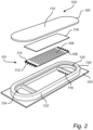
Fig. 2 is an exploded view of a fingerprint detection arrangement according to an example embodiment; -
Figs. 3a - 3b schematically illustrate example embodiments of the fingerprint detection arrangement when the finger is placed on the fingerprint sensor at two different positions; -
Fig. 4 is an exploded view of a fingerprint detection arrangement according to another example embodiment; -
Fig. 5 is a flow chart of a method of enrolling a fingerprint of a user's finger according to an example embodiment; and -
Fig. 6 is a flow chart of a method for authenticating a user of an electronic device according to an example embodiment. - The present invention will now be described more fully hereinafter with reference to the accompanying drawings, in which exemplary embodiments of the invention are shown. The invention may, however, be embodied in many different forms and should not be construed as limited to the embodiments set forth herein; rather, these embodiments are provided for thoroughness and completeness. Like reference character refer to like elements throughout the description.
-
Fig. 1 is a perspective view of a schematic illustration of anelectronic device 100 comprising afingerprint detection arrangement 102 and atouch sensor 104. Theelectronic device 100 is inFig. 1 depicted as a handheld electronic device in the form of a mobile phone. However, it should be readily understood that the invention is equally applicable for other types of electronic devices such as e.g. a wearable device, a tablet, etc. Thus, thefingerprint detection arrangement 102 can be used for such electronic devices requiring a way to identify and/or authenticate a user. Theelectronic device 100 further comprises acontrol unit 140 connected to below describedfingerprint sensor 101 andoptical sensor 130. Thecontrol unit 140 is merely schematically illustrated for simplicity of understanding. - With reference to
Fig. 2 , a schematic illustration of an exploded view of an example embodiment of thefingerprint detection arrangement 102 is depicted. Thefingerprint detection arrangement 102 inFig. 2 comprises afingerprint sensor 101 for capturing an image of a user's finger. The fingerprint sensor comprises asubstrate 103 comprising readout circuitry (also referred to as a control unit, not shown) for reading information provided by afingerprint sensing chip 106 which is arranged on thesubstrate 103. Thesubstrate 103 may be a conventional printed circuit board (PCB), a flexible substrate, or any other type of substrate or carrier suitable for use in the application at hand. - Moreover, the
sensing chip 106 further comprises a plurality ofsensing elements 108 having a surface defining a sensing plane. Eachsensing element 108 is configured to provide a signal indicative of an electromagnetic coupling between the sensing element and a finger placed on theexterior surface 110 of thefingerprint sensing device 102. The signal from each of thesensing elements 108 is provided to the readout circuitry of the substrate by means of a plurality ofbond wires 112 arranged between a set of respectivefirst bond pads 114 located on thesensing chip 106 and a set of respectivesecond bond pads 116 located on thesubstrate 103, thereby electrically connecting thesensing chip 106 to the readout circuitry of thesubstrate 103. The signal from thesensing elements 108 may, instead of thebond wires 112, be connected to the readout circuit of thesubstrate 103 by means of vertical interconnection access (VIA) through thesensing chip 106, etc. - As is further depicted in
Fig. 2 , thefingerprint sensor 101 comprises an adhesive 118 for mechanically attaching alight guiding structure 120 in the form of a protective plate to thesensing chip 106. The adhesive is schematically illustrated as having the same size and shape as thesensing chip 106. Thelight guiding structure 120 may constitute any type of insulating transparent or semi-transparent material such as e.g. glass material or a polymeric material, or equivalents thereof, which material is suitable for use as a top layer forming a surface in a fingerprint sensing device. - Still further, the exemplifying
fingerprint detection arrangement 102 depicted inFig. 2 comprises asurrounding frame 122 which is arranged to fully surround and encircle thesensing chip 106. Moreover, thefingerprint detection arrangement 102 comprises anoptical sensor 130 connected on an interior surface of thesurrounding frame 122. Theoptical sensor 130 comprises alight emitting source 132 and alight receiving device 134. Hereby, and as will be described in further detail below with reference to the description ofFigs. 3a and 3b , thelight emitting source 132 is arranged to emit light through thelight guiding structure 120 and thelight receiving device 134 is arranged to receive the emitted light 132 after the light has interacted with the finger when the finger is placed on theexterior surface 110. - The
fingerprint sensor 101 inFig. 2 is preferably a capacitive fingerprint sensor, although it should be readily understood that other alternatives are conceivable, such as e.g. an ultrasonic fingerprint sensor, etc. - With reference to
Figs. 3a and 3b , further detailed description of the functionality of theoptical sensor 130 in connection to the use of thefingerprint sensor 101 is provided. InFigs. 3a and 3b , thesubstrate 103, sensingelements 108, thebond wires 112, theadhesive layer 118, as well as the surroundingframe 122 has been omitted for improving the illustration of the functionality of thefingerprint detection arrangement 102. - Reference is first made to
Fig. 3a which schematically illustrates afinger 202 placed on theexterior surface 110 at a first position thereon. The first position of thefinger 202 is here defined by means of a finger coordinatesystem 204 relative to a fingerprint detection arrangement coordinatesystem 206. In the example embodiment depicted inFig. 3a , thefinger 202 is positioned on theexterior surface 110 such that the x1-axis of thefinger 202 corresponds to the x-axis of the fingerprint detection arrangement, and the z1-axis of thefinger 202 corresponds to the z-axis of the fingerprint detection arrangement. - When the
finger 202 is positioned at the first position on theexterior surface 110, thefingerprint sensor 101 captures an image of the fingerprint and at substantially the same time, thelight emitting source 132 emits light through thelight guiding structure 120 towards the user'sfinger 202. After the emitted light has interacted with thefinger 202 it is received by thelight receiving device 134. The intensity of the received light, inFig. 3a denoted as I1 is compared to the intensity of the emitted light, denoted as Iem, such that a first light response profile can be determined. According to the example depicted inFig. 3a , the light intensity I1 of the received light is lower in comparison to the light intensity Iem of the emitted light, although the wavelength is kept the same. - Reference is now made to
Fig. 3b , which schematically illustrates thefinger 202 placed on theexterior surface 110 at a second position thereon. In the example embodiment depicted inFig. 3b , thefinger 202 is positioned on theexterior surface 110 such that the y1-axis of thefinger 202 corresponds to the x-axis of the fingerprint detection arrangement, and the z1-axis of thefinger 202 corresponds to the z-axis of thefingerprint detection arrangement 102. - In a similar manner as described above in relation to the description of
Fig. 3a , when thefinger 202 is positioned at the second position on theexterior surface 110, thefingerprint sensor 101 captures an image of the fingerprint and at substantially the same time, thelight emitting source 132 emits light through thelight guiding structure 120 towards the user'sfinger 202. After the emitted light has interacted with thefinger 202 it is received by thelight receiving device 134. The intensity of the received light, inFig. 3b denoted as I2 is compared to the intensity of the emitted light, denoted as Iem, such that a second light response profile can be determined. According to the example depicted inFig. 3b , the light intensity I2 of the received light is lower in comparison to the light intensity Iem of the emitted light, although the wavelength is kept the same. - When comparing the first and second light response profiles in
Figs. 3a - 3b , i.e. the comparison between the light intensity I1 of the received light for the first position and the light intensity I2 of the received light for the second position, it can be seen that the light intensities differ in dependence of the positon of thefinger 202. In the examples depicted inFigs. 3a and 3b , the light intensity is higher for the second position in comparison to the first position. - It should be readily understood that the x1-axis and the y1-axis of the finger coordinate
system 204 may naturally also be positioned at any angle relative to the x-axis and y-axis of the fingerprint detection arrangement coordinatesystem 206. - Moreover, the light intensity of the light received by the
light receiving device 134 may also be dependent on the pressure exposed by the finger on theexterior surface 110, as well as how large area of the finger being in contact with theexterior surface 110. The pressure can be determined by means of the fingerprint sensor. If the pressure is too high, the user may be requested to re-position the finger on the fingerprint sensor. - With reference to
Fig. 4 , a schematic illustration of an exploded view of another example embodiment of thefingerprint detection arrangement 402 is depicted. The difference between the embodiment depicted inFig. 4 and the embodiment depicted inFig. 2 is that thefingerprint detection arrangement 402 inFig. 4 comprises a plurality of optical sensors, and hence a plurality of light emittingsources 132 and a plurality oflight receiving devices 134. In the embodiment depicted inFig. 4 , the plurality of light emittingsources 132 and the plurality oflight receiving devices 134 are alternatingly arranged around the surroundingframe 122. - By means of the arrangement depicted in
Fig. 4 , the plurality of light emittingsources 132 and the plurality oflight receiving devices 134 can be selectively activated, preferably in dependence of the position of the finger on thefingerprint sensor 101. Hence, the specific position of the finger on thefingerprint sensor 101 can be determined by capturing an image of the fingerprint, where after it is determined which one, or which ones, of the plurality of light emittingsources 132 and the plurality oflight receiving devices 134 to be operated when determining the light response profile. Now, in order to describe a method of enrolling a fingerprint, as well as a non-claimed method for authenticating a user of anelectronic device 100, by using one of the above describedfingerprint detection arrangements Figs. 2-4 , reference is made toFigs. 5 and6 in combination with particularlyFigs. 3a - 3b . - Reference is first made to
Fig. 5 which illustrates a flow chart of a method of enrolling a fingerprint of a user's finger according to an example embodiment. - Firstly, when enrolling the fingerprint, the user of the
electronic device 100 places hisfinger 202 on theexterior surface 110 of thefingerprint detection arrangement fingerprint sensor 101 hereby captures 501 a first enrollment image of the fingerprint of the user'sfinger 202. The first enrollment image is thus specific for the captured image when thefinger 202 is placed at the specific first position on thefingerprint sensor 101. Thelight emitting device 132 thereafter, or simultaneously, emits 502 light towards the user'sfinger 202, which emitted light is received 503 by thelight receiving device 134. Based on the received light by thelight receiving device 134, a first light response profile is determined 504. As described above, the light response profile is preferably based on the intensity I1 of the light received at thelight receiving device 134. More preferably, the light response profile is based on the difference between the light intensity I1 of the light received at thelight receiving device 134 and the light intensity Iem emitted from thelight emitting source 132. Thereafter, a fingerprint template can be formed 505, which fingerprint template comprises a representation based on the first enrollment image and the first light response profile. In more detail, for a specific first position of thefinger 202 on thefingerprint sensor 101, there is provided an image of the fingerprint captured by thefingerprint sensor 101 as well as a light response profile based on the light intensity for such first position of thefinger 202 on thefingerprint sensor 101. - The enrollment of the user's finger thereafter preferably continues by positioning the
finger 202 at a plurality of positions on thefingerprint sensor 101, whereby each position will be associated with a specific captured image and a specific light response profile. - When using a
fingerprint detection arrangement 402 as depicted inFig. 4 , the step of emitting light may be performed by a selected one of the plurality of light emittingdevices 132, and the step of receiving the emitted light may be performed by a selected one of the plurality oflight receiving devices 134. The specificlight emitting device 132 andlight receiving device 134 used may be based on the specific position of the finger, which position is determined by thefingerprint sensor 101. Alternatively, each of the plurality of light emittingsources 132 emits light and each of thelight receiving devices 134 receives light, whereby a light response is formed by combining light intensity data of the light received by thelight receiving devices 134. - Reference is now made to
Fig. 6 which illustrates a flow chart of a non-claimed method for authenticating a user of theelectronic device 100 according to an example embodiment. - First, when trying to gain access to the
electronic device 100, the user places hisfinger 202 on theexterior surface 110 of thefingerprint detection arrangement light emitting device 132 thereafter, or simultaneously, emits 602 light towards the user'sfinger 202, which emitted light is received 603 by thelight receiving device 134. Based on the received light by thelight receiving device 134, a first light authentication response profile is determined 604. The first authentication image and the first light authentication response profile are matched 605 against a fingerprint template formed according to the above description in relation toFig. 5 . Hence, the first authentication image and the first light authentication response profile is matched against a fingerprint template comprising a fingerprint representation for a finger of the user for at least one previously enrolled position of the finger at the fingerprint sensor and an associated light response profile. - In the present context, an enrolled fingerprint should be understood to correspond to the fingerprint data of the user's finger which the user "previously" provided when activated/registered himself, as described above, with the fingerprint detection arrangement. Hence, the enrolled fingerprint corresponds to the fingerprint, or fingerprints, of the user of the electronic device. Within the context of the present disclosure, the expression "fingerprint data" should be interpreted broadly and to include both a regular "visual image" of a fingerprint of a finger as well as a set of measurements relating to the finger when acquired using the fingerprint sensor. Similarly, the "light response profile" corresponds to previously acquired metadata in the form of optical light for the specific position of the user's finger at the fingerprint sensor.
- Moreover, the expression "processing circuitry" should be understood to include any type of computing device, such as an ASIC, a micro-processor, etc. It should also be understood that the actual implementation of such a processing circuitry may be divided between more than a single device/circuit.
- The control functionality of the present disclosure may be implemented using existing control units or computer processors, or by a special purpose computer processor for an appropriate system, incorporated for this or another purpose, or by a hardwire system. Embodiments within the scope of the present disclosure include program products comprising machine-readable medium for carrying or having machine-executable instructions or data structures stored thereon. Such machine-readable media can be any available media that can be accessed by a general purpose or special purpose computer or other machine with a processor. By way of example, such machine-readable media can comprise RAM, ROM, EPROM, EEPROM, CD-ROM or other optical disk storage, magnetic disk storage or other magnetic storage devices, or any other medium which can be used to carry or store desired program code in the form of machine-executable instructions or data structures and which can be accessed by a general purpose or special purpose computer or other machine with a processor. When information is transferred or provided over a network or another communications connection (either hardwired, wireless, or a combination of hardwired or wireless) to a machine, the machine properly views the connection as a machine-readable medium. Thus, any such connection is properly termed a machine-readable medium. Combinations of the above are also included within the scope of machine-readable media. Machine-executable instructions include, for example, instructions and data which cause a general purpose computer, special purpose computer, or special purpose processing machines to perform a certain function or group of functions.
- Although the figures may show a sequence the order of the steps may differ from what is depicted. Also two or more steps may be performed concurrently or with partial concurrence. Such variation will depend on the software and hardware systems chosen and on designer choice. All such variations are within the scope of the disclosure. Likewise, software implementations could be accomplished with standard programming techniques with rule based logic and other logic to accomplish the various connection steps, processing steps, comparison steps and decision steps.
- The fingerprint sensor may be positioned on a side portion or on the backside of the electronic device. Hence, the present invention should not be construed as limited to a specific position of the fingerprint sensor.
- In the claims, the word "comprising" does not exclude other elements or steps, and the indefinite article "a" or "an" does not exclude a plurality. The mere fact that certain measures are recited in mutually different dependent claims does not indicate that a combination of these measured cannot be used to advantage.
Claims (6)
- A method of enrolling a fingerprint of a user's finger (202), by means of a fingerprint detection arrangement (102) comprising a fingerprint sensor (101) and an optical sensor (130) comprising a light emitting source (132) and a light receiving device (134), the method comprising the steps of:- capturing (501), by the fingerprint sensor (101), a first enrollment image of a fingerprint of a user's finger (202) placed on the fingerprint sensor (101), wherein a position of the user's finger (202) on the fingerprint sensor is set as a first position;- emitting (502) light, by the light emitting source (132) of the optical sensor (130), towards the user's finger (202);- determining an emitted light intensity (Iem) of the light emitted by the light emitting source (132);- receiving (503), by the light receiving device (134), light emitted by the light emitting source (132) when the finger (202) is placed at said first position on the fingerprint sensor (101);- determining a received light intensity (I1, I2) of the light received by the light receiving device (134);- determining (504) a first light response profile for the first position of the user's finger, the first light response profile being a difference in light intensity between the received light intensity and the emitted light intensity when the finger (202) is placed at the first position of the fingerprint sensor; and- forming (505) a first fingerprint sub template for the fingerprint when the finger (202) is placed at the first position of the fingerprint sensor, the first fingerprint sub template comprising a fingerprint representation comprising a combination of the first enrollment image and the first light response profile when the finger (202) is placed at the first position of the fingerprint sensor.
- The method according to claim 1, wherein the light emitting device is arranged to emit light of at least two distinct wavelengths, and the light receiving device is arranged to receive light of the at least two distinct wavelengths.
- The method according to any one of the preceding claims, further comprising the steps of:- capturing, by the fingerprint sensor (101), a second enrollment image of the fingerprint of the user's finger (202) placed on the fingerprint sensor (101) at a second position thereon, said second position being different in comparison to the first position;- emitting light, by the light emitting source (132) of the optical sensor (130), towards the user's finger (202);- receiving, by the light receiving device (134), the light emitted by the light emitting source (132) when the finger (202) is placed at said second position on the fingerprint sensor (101);- determining a second light response profile based on the light received by the light receiving device when the finger is placed at the second position on the fingerprint sensor; and- forming a second fingerprint sub template when the finger is placed at the second position, the second fingerprint sub template comprising a fingerprint representation comprising the second enrollment image and the second light response profile.
- The method according to claim 3, wherein the second position of the user's finger corresponds to a position being rotated on a surface of the fingerprint sensor relative to the first position.
- The method according to any one of claims 3 or 4, wherein the second position of the user's finger corresponds to a position being moved along a surface of the fingerprint sensor relative to the first position.
- A fingerprint detection arrangement (102, 402) comprising a fingerprint sensor (101) and an optical sensor (130), said optical sensor (130) comprising a light emitting source (132) and a light receiving device (134), and a control unit (140) connected to the fingerprint sensor and said optical sensor, wherein, when a user enrolls a fingerprint, the control unit (140) is configured to:- control the fingerprint sensor to capture a first enrollment image of a fingerprint of a user's finger (202) when the finger is placed on the fingerprint sensor (101), wherein a position of the user's finger (202) on the fingerprint sensor is set as a first position;- control the light emitting source of the optical sensor (130) to emit light towards the user's finger (202);- determine an emitted light intensity (Iem) of the light emitted by the light emitting source (132);- control the light receiving device (134) to receive the light emitted by the light emitting source when the finger is placed at said first position on the fingerprint sensor (101);- determining a received light intensity (I1, I2) of the light received by the light receiving device (134);- determine a first light response profile for the first position of the user's finger, the first light response profile being a difference in light intensity between the received light intensity and the emitted light intensity when the finger (202) is placed at the first position of the fingerprint sensor; and- form a first fingerprint sub template for the fingerprint when the finger (202) is placed at the first position of the fingerprint sensor, the first fingerprint sub template comprising a fingerprint representation comprising a combination of the first enrollment image and the first light response profile when the finger (202) is placed at the first position of the fingerprint sensor.
Applications Claiming Priority (2)
| Application Number | Priority Date | Filing Date | Title |
|---|---|---|---|
| SE1750809 | 2017-06-22 | ||
| PCT/SE2018/050662 WO2018236280A1 (en) | 2017-06-22 | 2018-06-20 | METHOD FOR REGISTERING A DIGITAL FOOTPRINT |
Publications (3)
| Publication Number | Publication Date |
|---|---|
| EP3642759A1 EP3642759A1 (en) | 2020-04-29 |
| EP3642759A4 EP3642759A4 (en) | 2021-03-17 |
| EP3642759B1 true EP3642759B1 (en) | 2024-08-07 |
Family
ID=64737790
Family Applications (1)
| Application Number | Title | Priority Date | Filing Date |
|---|---|---|---|
| EP18819613.3A Active EP3642759B1 (en) | 2017-06-22 | 2018-06-20 | Method of enrolling a fingerprint |
Country Status (4)
| Country | Link |
|---|---|
| US (1) | US10839240B2 (en) |
| EP (1) | EP3642759B1 (en) |
| CN (1) | CN110753925A (en) |
| WO (1) | WO2018236280A1 (en) |
Families Citing this family (3)
| Publication number | Priority date | Publication date | Assignee | Title |
|---|---|---|---|---|
| CN110383286B (en) * | 2019-05-22 | 2023-05-30 | 深圳市汇顶科技股份有限公司 | Method for biometric identification, fingerprint identification device and electronic device |
| KR20220007999A (en) * | 2020-07-13 | 2022-01-20 | 삼성전자주식회사 | Electronic device including ultrasonic device and method for obtaining ppg signal thereof |
| US11620852B2 (en) * | 2021-09-08 | 2023-04-04 | Omnivision Technologies, Inc. | Method for detecting spoof fingerprints with an under-display fingerprint sensor |
Citations (2)
| Publication number | Priority date | Publication date | Assignee | Title |
|---|---|---|---|---|
| EP2848196B1 (en) * | 2013-07-26 | 2018-06-27 | Hitachi, Ltd. | Apparatus for blood vessel imaging |
| EP2782048B1 (en) * | 2013-03-22 | 2020-11-11 | Hitachi Industry & Control Solutions, Ltd. | Blood vessel image taking device |
Family Cites Families (15)
| Publication number | Priority date | Publication date | Assignee | Title |
|---|---|---|---|---|
| JP2003050993A (en) * | 2001-08-06 | 2003-02-21 | Omron Corp | Fingerprint reading method and fingerprint reading device |
| FR2850190B1 (en) | 2003-01-21 | 2006-04-28 | Atmel Grenoble Sa | METHOD AND DEVICE FOR RECOGNIZING PERSON |
| US7627151B2 (en) * | 2003-04-04 | 2009-12-01 | Lumidigm, Inc. | Systems and methods for improved biometric feature definition |
| CA2569440A1 (en) | 2004-06-01 | 2006-09-08 | Lumidigm, Inc. | Multispectral imaging biometrics |
| JP4951291B2 (en) * | 2006-08-08 | 2012-06-13 | 株式会社日立メディアエレクトロニクス | Biometric authentication device |
| US8073204B2 (en) | 2007-12-31 | 2011-12-06 | Authentec, Inc. | Hybrid multi-sensor biometric identification device |
| US8907897B2 (en) * | 2009-06-16 | 2014-12-09 | Intel Corporation | Optical capacitive thumb control with pressure sensor |
| KR101376228B1 (en) | 2013-07-17 | 2014-04-01 | 실리콘 디스플레이 (주) | Fingerprint sensor capable of sensing fingerprint by optical method and capacitive method |
| TWI592854B (en) * | 2014-12-18 | 2017-07-21 | 指紋卡公司 | Fingerprint authentication using touch sensor data |
| US9514352B2 (en) * | 2014-12-18 | 2016-12-06 | Eaton Corporation | Fingerprint enrollment using touch sensor data |
| US10410037B2 (en) * | 2015-06-18 | 2019-09-10 | Shenzhen GOODIX Technology Co., Ltd. | Under-screen optical sensor module for on-screen fingerprint sensing implementing imaging lens, extra illumination or optical collimator array |
| CN105184248B (en) * | 2015-08-28 | 2019-03-12 | 京东方科技集团股份有限公司 | A fingerprint identification device and fingerprint identification system |
| CN107004126A (en) * | 2015-11-02 | 2017-08-01 | 深圳市汇顶科技股份有限公司 | Multifunctional fingerprint sensor with anti-fingerprint spoofing optical sensing |
| CN106709413B (en) * | 2015-12-31 | 2020-12-08 | 深圳市汇顶科技股份有限公司 | Fingerprint identification device and mobile terminal |
| CN106526944A (en) * | 2017-01-24 | 2017-03-22 | 京东方科技集团股份有限公司 | Display substrate and display device |
-
2018
- 2018-06-20 CN CN201880039072.3A patent/CN110753925A/en active Pending
- 2018-06-20 US US16/622,690 patent/US10839240B2/en active Active
- 2018-06-20 EP EP18819613.3A patent/EP3642759B1/en active Active
- 2018-06-20 WO PCT/SE2018/050662 patent/WO2018236280A1/en not_active Ceased
Patent Citations (2)
| Publication number | Priority date | Publication date | Assignee | Title |
|---|---|---|---|---|
| EP2782048B1 (en) * | 2013-03-22 | 2020-11-11 | Hitachi Industry & Control Solutions, Ltd. | Blood vessel image taking device |
| EP2848196B1 (en) * | 2013-07-26 | 2018-06-27 | Hitachi, Ltd. | Apparatus for blood vessel imaging |
Also Published As
| Publication number | Publication date |
|---|---|
| CN110753925A (en) | 2020-02-04 |
| US10839240B2 (en) | 2020-11-17 |
| WO2018236280A1 (en) | 2018-12-27 |
| EP3642759A4 (en) | 2021-03-17 |
| EP3642759A1 (en) | 2020-04-29 |
| US20200117931A1 (en) | 2020-04-16 |
Similar Documents
| Publication | Publication Date | Title |
|---|---|---|
| US9646193B2 (en) | Fingerprint authentication using touch sensor data | |
| EP3690701B1 (en) | Fingerprint recognition method, fingerprint recognition device and terminal equipment | |
| CN107004114B (en) | Blood vessel image capturing device and personal authentication system | |
| US8326004B2 (en) | Fingerprint recognition device and user authentication method for card including the fingerprint recognition device | |
| KR101222308B1 (en) | Biometric information processing device and recording medium | |
| JP6467852B2 (en) | Biological information correction apparatus, biological information correction method, and biological information correction computer program | |
| JP6005750B2 (en) | Authentication apparatus and authentication method | |
| US20110222740A1 (en) | Finger vein authentication unit | |
| KR101603469B1 (en) | Biometric authentication device, biometric authentication method, and biometric authentication computer program | |
| US10839240B2 (en) | Method of enrolling a fingerprint | |
| TW201820103A (en) | Optical spoof detection | |
| JP5982311B2 (en) | Blood vessel imaging device | |
| WO2019212791A1 (en) | Location matched small segment fingerprint reader | |
| JP2021089577A (en) | Imaging apparatus and authentication device | |
| US11048786B2 (en) | Techniques for fingerprint detection and user authentication | |
| JP4945505B2 (en) | Biological information processing device | |
| KR20170033058A (en) | Sensor package and method for distinguishing fake fingerprint of the same | |
| CN112270260A (en) | Identification method and electronic equipment | |
| KR100586958B1 (en) | Optical fingerprint authentication system with wide contact surface of fingerprint | |
| JP2019049809A (en) | Biometric information acquisition apparatus, and electronic device provided with biometric information acquisition apparatus |
Legal Events
| Date | Code | Title | Description |
|---|---|---|---|
| STAA | Information on the status of an ep patent application or granted ep patent |
Free format text: STATUS: THE INTERNATIONAL PUBLICATION HAS BEEN MADE |
|
| PUAI | Public reference made under article 153(3) epc to a published international application that has entered the european phase |
Free format text: ORIGINAL CODE: 0009012 |
|
| STAA | Information on the status of an ep patent application or granted ep patent |
Free format text: STATUS: REQUEST FOR EXAMINATION WAS MADE |
|
| 17P | Request for examination filed |
Effective date: 20191205 |
|
| AK | Designated contracting states |
Kind code of ref document: A1 Designated state(s): AL AT BE BG CH CY CZ DE DK EE ES FI FR GB GR HR HU IE IS IT LI LT LU LV MC MK MT NL NO PL PT RO RS SE SI SK SM TR |
|
| AX | Request for extension of the european patent |
Extension state: BA ME |
|
| DAV | Request for validation of the european patent (deleted) | ||
| DAX | Request for extension of the european patent (deleted) | ||
| A4 | Supplementary search report drawn up and despatched |
Effective date: 20210212 |
|
| RIC1 | Information provided on ipc code assigned before grant |
Ipc: G06K 9/00 20060101AFI20210209BHEP Ipc: G06F 21/32 20130101ALI20210209BHEP Ipc: A61B 5/117 20160101ALI20210209BHEP |
|
| RAP1 | Party data changed (applicant data changed or rights of an application transferred) |
Owner name: FINGERPRINT CARDS ANACATUM IP AB |
|
| STAA | Information on the status of an ep patent application or granted ep patent |
Free format text: STATUS: EXAMINATION IS IN PROGRESS |
|
| 17Q | First examination report despatched |
Effective date: 20230116 |
|
| REG | Reference to a national code |
Ref legal event code: R079 Free format text: PREVIOUS MAIN CLASS: G06K0009000000 Ref country code: DE Ref legal event code: R079 Ref document number: 602018072863 Country of ref document: DE Free format text: PREVIOUS MAIN CLASS: G06K0009000000 Ipc: G06V0010100000 |
|
| GRAP | Despatch of communication of intention to grant a patent |
Free format text: ORIGINAL CODE: EPIDOSNIGR1 |
|
| STAA | Information on the status of an ep patent application or granted ep patent |
Free format text: STATUS: GRANT OF PATENT IS INTENDED |
|
| RIC1 | Information provided on ipc code assigned before grant |
Ipc: G06V 40/50 20220101ALI20240307BHEP Ipc: G06V 40/13 20220101ALI20240307BHEP Ipc: G06V 10/10 20220101AFI20240307BHEP |
|
| INTG | Intention to grant announced |
Effective date: 20240321 |
|
| GRAS | Grant fee paid |
Free format text: ORIGINAL CODE: EPIDOSNIGR3 |
|
| GRAA | (expected) grant |
Free format text: ORIGINAL CODE: 0009210 |
|
| STAA | Information on the status of an ep patent application or granted ep patent |
Free format text: STATUS: THE PATENT HAS BEEN GRANTED |
|
| AK | Designated contracting states |
Kind code of ref document: B1 Designated state(s): AL AT BE BG CH CY CZ DE DK EE ES FI FR GB GR HR HU IE IS IT LI LT LU LV MC MK MT NL NO PL PT RO RS SE SI SK SM TR |
|
| REG | Reference to a national code |
Ref country code: GB Ref legal event code: FG4D |
|
| REG | Reference to a national code |
Ref country code: CH Ref legal event code: EP |
|
| REG | Reference to a national code |
Ref country code: IE Ref legal event code: FG4D |
|
| REG | Reference to a national code |
Ref country code: DE Ref legal event code: R096 Ref document number: 602018072863 Country of ref document: DE |
|
| REG | Reference to a national code |
Ref country code: LT Ref legal event code: MG9D |
|
| REG | Reference to a national code |
Ref country code: NL Ref legal event code: MP Effective date: 20240807 |
|
| PG25 | Lapsed in a contracting state [announced via postgrant information from national office to epo] |
Ref country code: NO Free format text: LAPSE BECAUSE OF FAILURE TO SUBMIT A TRANSLATION OF THE DESCRIPTION OR TO PAY THE FEE WITHIN THE PRESCRIBED TIME-LIMIT Effective date: 20241107 |
|
| REG | Reference to a national code |
Ref country code: AT Ref legal event code: MK05 Ref document number: 1711814 Country of ref document: AT Kind code of ref document: T Effective date: 20240807 |
|
| PG25 | Lapsed in a contracting state [announced via postgrant information from national office to epo] |
Ref country code: NL Free format text: LAPSE BECAUSE OF FAILURE TO SUBMIT A TRANSLATION OF THE DESCRIPTION OR TO PAY THE FEE WITHIN THE PRESCRIBED TIME-LIMIT Effective date: 20240807 Ref country code: PL Free format text: LAPSE BECAUSE OF FAILURE TO SUBMIT A TRANSLATION OF THE DESCRIPTION OR TO PAY THE FEE WITHIN THE PRESCRIBED TIME-LIMIT Effective date: 20240807 Ref country code: PT Free format text: LAPSE BECAUSE OF FAILURE TO SUBMIT A TRANSLATION OF THE DESCRIPTION OR TO PAY THE FEE WITHIN THE PRESCRIBED TIME-LIMIT Effective date: 20241209 Ref country code: FI Free format text: LAPSE BECAUSE OF FAILURE TO SUBMIT A TRANSLATION OF THE DESCRIPTION OR TO PAY THE FEE WITHIN THE PRESCRIBED TIME-LIMIT Effective date: 20240807 Ref country code: GR Free format text: LAPSE BECAUSE OF FAILURE TO SUBMIT A TRANSLATION OF THE DESCRIPTION OR TO PAY THE FEE WITHIN THE PRESCRIBED TIME-LIMIT Effective date: 20241108 |
|
| PG25 | Lapsed in a contracting state [announced via postgrant information from national office to epo] |
Ref country code: BG Free format text: LAPSE BECAUSE OF FAILURE TO SUBMIT A TRANSLATION OF THE DESCRIPTION OR TO PAY THE FEE WITHIN THE PRESCRIBED TIME-LIMIT Effective date: 20240807 |
|
| PG25 | Lapsed in a contracting state [announced via postgrant information from national office to epo] |
Ref country code: LV Free format text: LAPSE BECAUSE OF FAILURE TO SUBMIT A TRANSLATION OF THE DESCRIPTION OR TO PAY THE FEE WITHIN THE PRESCRIBED TIME-LIMIT Effective date: 20240807 |
|
| PG25 | Lapsed in a contracting state [announced via postgrant information from national office to epo] |
Ref country code: IS Free format text: LAPSE BECAUSE OF FAILURE TO SUBMIT A TRANSLATION OF THE DESCRIPTION OR TO PAY THE FEE WITHIN THE PRESCRIBED TIME-LIMIT Effective date: 20241207 Ref country code: AT Free format text: LAPSE BECAUSE OF FAILURE TO SUBMIT A TRANSLATION OF THE DESCRIPTION OR TO PAY THE FEE WITHIN THE PRESCRIBED TIME-LIMIT Effective date: 20240807 |
|
| PG25 | Lapsed in a contracting state [announced via postgrant information from national office to epo] |
Ref country code: HR Free format text: LAPSE BECAUSE OF FAILURE TO SUBMIT A TRANSLATION OF THE DESCRIPTION OR TO PAY THE FEE WITHIN THE PRESCRIBED TIME-LIMIT Effective date: 20240807 |
|
| PG25 | Lapsed in a contracting state [announced via postgrant information from national office to epo] |
Ref country code: ES Free format text: LAPSE BECAUSE OF FAILURE TO SUBMIT A TRANSLATION OF THE DESCRIPTION OR TO PAY THE FEE WITHIN THE PRESCRIBED TIME-LIMIT Effective date: 20240807 Ref country code: RS Free format text: LAPSE BECAUSE OF FAILURE TO SUBMIT A TRANSLATION OF THE DESCRIPTION OR TO PAY THE FEE WITHIN THE PRESCRIBED TIME-LIMIT Effective date: 20241107 |
|
| PG25 | Lapsed in a contracting state [announced via postgrant information from national office to epo] |
Ref country code: RS Free format text: LAPSE BECAUSE OF FAILURE TO SUBMIT A TRANSLATION OF THE DESCRIPTION OR TO PAY THE FEE WITHIN THE PRESCRIBED TIME-LIMIT Effective date: 20241107 Ref country code: PT Free format text: LAPSE BECAUSE OF FAILURE TO SUBMIT A TRANSLATION OF THE DESCRIPTION OR TO PAY THE FEE WITHIN THE PRESCRIBED TIME-LIMIT Effective date: 20241209 Ref country code: PL Free format text: LAPSE BECAUSE OF FAILURE TO SUBMIT A TRANSLATION OF THE DESCRIPTION OR TO PAY THE FEE WITHIN THE PRESCRIBED TIME-LIMIT Effective date: 20240807 Ref country code: NO Free format text: LAPSE BECAUSE OF FAILURE TO SUBMIT A TRANSLATION OF THE DESCRIPTION OR TO PAY THE FEE WITHIN THE PRESCRIBED TIME-LIMIT Effective date: 20241107 Ref country code: NL Free format text: LAPSE BECAUSE OF FAILURE TO SUBMIT A TRANSLATION OF THE DESCRIPTION OR TO PAY THE FEE WITHIN THE PRESCRIBED TIME-LIMIT Effective date: 20240807 Ref country code: LV Free format text: LAPSE BECAUSE OF FAILURE TO SUBMIT A TRANSLATION OF THE DESCRIPTION OR TO PAY THE FEE WITHIN THE PRESCRIBED TIME-LIMIT Effective date: 20240807 Ref country code: IS Free format text: LAPSE BECAUSE OF FAILURE TO SUBMIT A TRANSLATION OF THE DESCRIPTION OR TO PAY THE FEE WITHIN THE PRESCRIBED TIME-LIMIT Effective date: 20241207 Ref country code: HR Free format text: LAPSE BECAUSE OF FAILURE TO SUBMIT A TRANSLATION OF THE DESCRIPTION OR TO PAY THE FEE WITHIN THE PRESCRIBED TIME-LIMIT Effective date: 20240807 Ref country code: GR Free format text: LAPSE BECAUSE OF FAILURE TO SUBMIT A TRANSLATION OF THE DESCRIPTION OR TO PAY THE FEE WITHIN THE PRESCRIBED TIME-LIMIT Effective date: 20241108 Ref country code: FI Free format text: LAPSE BECAUSE OF FAILURE TO SUBMIT A TRANSLATION OF THE DESCRIPTION OR TO PAY THE FEE WITHIN THE PRESCRIBED TIME-LIMIT Effective date: 20240807 Ref country code: ES Free format text: LAPSE BECAUSE OF FAILURE TO SUBMIT A TRANSLATION OF THE DESCRIPTION OR TO PAY THE FEE WITHIN THE PRESCRIBED TIME-LIMIT Effective date: 20240807 Ref country code: BG Free format text: LAPSE BECAUSE OF FAILURE TO SUBMIT A TRANSLATION OF THE DESCRIPTION OR TO PAY THE FEE WITHIN THE PRESCRIBED TIME-LIMIT Effective date: 20240807 Ref country code: AT Free format text: LAPSE BECAUSE OF FAILURE TO SUBMIT A TRANSLATION OF THE DESCRIPTION OR TO PAY THE FEE WITHIN THE PRESCRIBED TIME-LIMIT Effective date: 20240807 |
|
| PG25 | Lapsed in a contracting state [announced via postgrant information from national office to epo] |
Ref country code: DK Free format text: LAPSE BECAUSE OF FAILURE TO SUBMIT A TRANSLATION OF THE DESCRIPTION OR TO PAY THE FEE WITHIN THE PRESCRIBED TIME-LIMIT Effective date: 20240807 Ref country code: RO Free format text: LAPSE BECAUSE OF FAILURE TO SUBMIT A TRANSLATION OF THE DESCRIPTION OR TO PAY THE FEE WITHIN THE PRESCRIBED TIME-LIMIT Effective date: 20240807 Ref country code: SM Free format text: LAPSE BECAUSE OF FAILURE TO SUBMIT A TRANSLATION OF THE DESCRIPTION OR TO PAY THE FEE WITHIN THE PRESCRIBED TIME-LIMIT Effective date: 20240807 |
|
| PG25 | Lapsed in a contracting state [announced via postgrant information from national office to epo] |
Ref country code: EE Free format text: LAPSE BECAUSE OF FAILURE TO SUBMIT A TRANSLATION OF THE DESCRIPTION OR TO PAY THE FEE WITHIN THE PRESCRIBED TIME-LIMIT Effective date: 20240807 |
|
| PG25 | Lapsed in a contracting state [announced via postgrant information from national office to epo] |
Ref country code: CZ Free format text: LAPSE BECAUSE OF FAILURE TO SUBMIT A TRANSLATION OF THE DESCRIPTION OR TO PAY THE FEE WITHIN THE PRESCRIBED TIME-LIMIT Effective date: 20240807 |
|
| PG25 | Lapsed in a contracting state [announced via postgrant information from national office to epo] |
Ref country code: SK Free format text: LAPSE BECAUSE OF FAILURE TO SUBMIT A TRANSLATION OF THE DESCRIPTION OR TO PAY THE FEE WITHIN THE PRESCRIBED TIME-LIMIT Effective date: 20240807 |
|
| REG | Reference to a national code |
Ref country code: DE Ref legal event code: R097 Ref document number: 602018072863 Country of ref document: DE |
|
| PLBE | No opposition filed within time limit |
Free format text: ORIGINAL CODE: 0009261 |
|
| STAA | Information on the status of an ep patent application or granted ep patent |
Free format text: STATUS: NO OPPOSITION FILED WITHIN TIME LIMIT |
|
| 26N | No opposition filed |
Effective date: 20250508 |
|
| PG25 | Lapsed in a contracting state [announced via postgrant information from national office to epo] |
Ref country code: SE Free format text: LAPSE BECAUSE OF FAILURE TO SUBMIT A TRANSLATION OF THE DESCRIPTION OR TO PAY THE FEE WITHIN THE PRESCRIBED TIME-LIMIT Effective date: 20240807 |
|
| REG | Reference to a national code |
Ref country code: DE Ref legal event code: R119 Ref document number: 602018072863 Country of ref document: DE |
|
| REG | Reference to a national code |
Ref country code: CH Ref legal event code: H13 Free format text: ST27 STATUS EVENT CODE: U-0-0-H10-H13 (AS PROVIDED BY THE NATIONAL OFFICE) Effective date: 20260127 |
|
| PG25 | Lapsed in a contracting state [announced via postgrant information from national office to epo] |
Ref country code: IT Free format text: LAPSE BECAUSE OF FAILURE TO SUBMIT A TRANSLATION OF THE DESCRIPTION OR TO PAY THE FEE WITHIN THE PRESCRIBED TIME-LIMIT Effective date: 20240807 |
|
| PG25 | Lapsed in a contracting state [announced via postgrant information from national office to epo] |
Ref country code: MC Free format text: LAPSE BECAUSE OF FAILURE TO SUBMIT A TRANSLATION OF THE DESCRIPTION OR TO PAY THE FEE WITHIN THE PRESCRIBED TIME-LIMIT Effective date: 20240807 |
|
| PG25 | Lapsed in a contracting state [announced via postgrant information from national office to epo] |
Ref country code: LU Free format text: LAPSE BECAUSE OF NON-PAYMENT OF DUE FEES Effective date: 20250620 |
|
| GBPC | Gb: european patent ceased through non-payment of renewal fee |
Effective date: 20250620 |
|
| REG | Reference to a national code |
Ref country code: BE Ref legal event code: MM Effective date: 20250630 |
|
| PG25 | Lapsed in a contracting state [announced via postgrant information from national office to epo] |
Ref country code: GB Free format text: LAPSE BECAUSE OF NON-PAYMENT OF DUE FEES Effective date: 20250620 |
|
| PG25 | Lapsed in a contracting state [announced via postgrant information from national office to epo] |
Ref country code: DE Free format text: LAPSE BECAUSE OF NON-PAYMENT OF DUE FEES Effective date: 20260101 Ref country code: IE Free format text: LAPSE BECAUSE OF NON-PAYMENT OF DUE FEES Effective date: 20250620 |
|
| PG25 | Lapsed in a contracting state [announced via postgrant information from national office to epo] |
Ref country code: BE Free format text: LAPSE BECAUSE OF NON-PAYMENT OF DUE FEES Effective date: 20250630 |
|
| PG25 | Lapsed in a contracting state [announced via postgrant information from national office to epo] |
Ref country code: FR Free format text: LAPSE BECAUSE OF NON-PAYMENT OF DUE FEES Effective date: 20250630 |
|
| PG25 | Lapsed in a contracting state [announced via postgrant information from national office to epo] |
Ref country code: CH Free format text: LAPSE BECAUSE OF NON-PAYMENT OF DUE FEES Effective date: 20250630 |